WO2024236754A1 - 回転電機、回転電機ユニットおよび電動車両 - Google Patents
回転電機、回転電機ユニットおよび電動車両 Download PDFInfo
- Publication number
- WO2024236754A1 WO2024236754A1 PCT/JP2023/018388 JP2023018388W WO2024236754A1 WO 2024236754 A1 WO2024236754 A1 WO 2024236754A1 JP 2023018388 W JP2023018388 W JP 2023018388W WO 2024236754 A1 WO2024236754 A1 WO 2024236754A1
- Authority
- WO
- WIPO (PCT)
- Prior art keywords
- rotating electric
- electric machine
- permanent magnet
- rotor
- block
- Prior art date
- Legal status (The legal status is an assumption and is not a legal conclusion. Google has not performed a legal analysis and makes no representation as to the accuracy of the status listed.)
- Ceased
Links
Images










Classifications
-
- H—ELECTRICITY
- H02—GENERATION; CONVERSION OR DISTRIBUTION OF ELECTRIC POWER
- H02K—DYNAMO-ELECTRIC MACHINES
- H02K1/00—Details of the magnetic circuit
- H02K1/06—Details of the magnetic circuit characterised by the shape, form or construction
- H02K1/08—Salient poles
-
- H—ELECTRICITY
- H02—GENERATION; CONVERSION OR DISTRIBUTION OF ELECTRIC POWER
- H02K—DYNAMO-ELECTRIC MACHINES
- H02K1/00—Details of the magnetic circuit
- H02K1/06—Details of the magnetic circuit characterised by the shape, form or construction
- H02K1/22—Rotating parts of the magnetic circuit
- H02K1/27—Rotor cores with permanent magnets
- H02K1/2706—Inner rotors
- H02K1/272—Inner rotors the magnetisation axis of the magnets being perpendicular to the rotor axis
- H02K1/274—Inner rotors the magnetisation axis of the magnets being perpendicular to the rotor axis the rotor consisting of two or more circumferentially positioned magnets
- H02K1/2753—Inner rotors the magnetisation axis of the magnets being perpendicular to the rotor axis the rotor consisting of two or more circumferentially positioned magnets the rotor consisting of magnets or groups of magnets arranged with alternating polarity
- H02K1/276—Magnets embedded in the magnetic core, e.g. interior permanent magnets [IPM]
-
- H—ELECTRICITY
- H02—GENERATION; CONVERSION OR DISTRIBUTION OF ELECTRIC POWER
- H02K—DYNAMO-ELECTRIC MACHINES
- H02K9/00—Arrangements for cooling or ventilating
- H02K9/19—Arrangements for cooling or ventilating for machines with closed casing and closed-circuit cooling using a liquid cooling medium, e.g. oil
Definitions
- This application relates to a rotating electric machine, a rotating electric machine unit, and an electric vehicle.
- Electric vehicle rotating motors are required to be small and have high output, and it is effective to reduce the maximum temperature by improving the uniformity of the temperature distribution inside the rotating motor.
- permanent magnet synchronous motors which have permanent magnets in the rotor, are often used for electric vehicle rotating motors in order to achieve high torque.
- Patent Document 1 adjusts the temperature distribution inside the coil by changing the cross-sectional area of the coil wire, but it is not possible to improve the uniformity of the temperature distribution in a rotor with permanent magnets.
- This application discloses technology to solve the problems described above, and aims to improve the uniformity of temperature distribution within a rotating electric machine having a permanent magnet in the rotor, thereby reducing the maximum temperature and achieving a smaller size and higher output. It also aims to provide a rotating electric machine unit and an electric vehicle equipped with such a rotating electric machine.
- the rotating electric machine disclosed in the present application comprises a cylindrical rotor having at least one first permanent magnet and at least one second permanent magnet for each pole, and a cylindrical stator having a stator core and windings and arranged with a gap between the rotor and the stator.
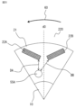
- the first permanent magnet is arranged in a position advanced in the forward rotation direction of the rotor with respect to the d-axis of the rotor
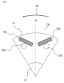
- the second permanent magnet is arranged in a position delayed in the forward rotation direction of the rotor with respect to the d-axis of the rotor.
- one of the first and second permanent magnets is a high heat generation magnet and the other is a low heat generation magnet, and the rotor is cooled by heat transfer via a fluid, with the heat dissipation of the high heat generation magnet being greater than that of the low heat generation magnet.
- the rotating electric machine unit disclosed in the present application includes the rotating electric machine and an inverter that drives and controls the rotating electric machine, the rotor includes a first block that includes the first permanent magnet for each pole, and a second block that includes the second permanent magnet for each pole, arranged in the axial direction, and the inverter is disposed on one axial end side of the rotating electric machine, on the side of the first and second blocks that is closer to the block that includes the low heat generating magnet.
- the rotating electric machine unit disclosed in the present application includes the rotating electric machine and a reducer connected to the rotating electric machine, the rotor includes a first block having the first permanent magnet for each pole and a second block having the second permanent magnet for each pole, arranged in the axial direction, and the reducer is disposed on one axial end side of the rotating electric machine, on the side of the first and second blocks that is closer to the block having the low heat generating magnet.
- the electric vehicle disclosed in this application is driven by the rotating electric machine, and the forward rotation of the rotor is the main rotation direction, which is the direction in which the electric vehicle moves forward.
- the rotating electric machine disclosed in the present application is a rotating electric machine having a permanent magnet in the rotor, which can improve the uniformity of temperature distribution within the rotating electric machine, reduce the maximum temperature, and achieve a smaller size and higher output. It is also possible to realize a rotating electric machine unit and an electric vehicle that include such a rotating electric machine.
- FIG. 1 is a block diagram showing a system configuration of an electric vehicle according to a first embodiment.
- 1 is a cross-sectional view showing a schematic configuration of a rotating electric machine according to a first embodiment.
- 1 is a cross-sectional view showing a configuration of a rotor according to a first embodiment.
- FIG. 2 is a perspective view illustrating the configuration of one pole of a rotor according to the first embodiment. 2 is a cross-sectional view showing the configuration of a first block for one pole of a rotor according to the first embodiment.
- FIG. 4 is a cross-sectional view showing a configuration of a second block for one pole of a rotor according to the first embodiment.
- FIG. 4 is a diagram showing the position of a field magnet in a first block of the rotor according to the first embodiment, using electrical angles.
- FIG. 5 is a diagram showing the position of a field magnet in a second block of the rotor according to the first embodiment, using electrical angles.
- FIG. 11 is a cross-sectional view showing a configuration of a rotor and a stator according to a second embodiment.
- 13A and 13B are diagrams illustrating teeth portions in axial end regions according to a second embodiment.
- 13A and 13B are diagrams illustrating a teeth portion in an axial central region according to a second embodiment.
- 13A to 13C are views showing a teeth portion in the axial center region according to another example of embodiment 2.
- FIG. 11 is a cross-sectional view showing the configuration of a rotor according to a third embodiment.
- FIG. 11 is a cross-sectional view showing the configuration of a first block for one rotor pole according to embodiment 3.
- FIG. 11 is a cross-sectional view showing the configuration of a second block for one rotor pole according to embodiment 3.
- FIG. 13 is a cross-sectional view showing the configuration of a rotor according to a fourth embodiment.
- FIG. 13 is a block diagram showing a system configuration of an electric vehicle according to a fifth embodiment.
- FIG. 23 is a cross-sectional view showing the configuration of a second block for one rotor pole according to embodiment 6.
- FIG. 13 is a cross-sectional view showing a schematic configuration of a rotating electrical machine unit according to a seventh embodiment.
- FIG. 21 is a partial detailed view of FIG. 20 .
- 13 is a cross-sectional view showing a schematic configuration of a rotating electric machine unit according to an eighth embodiment.
- FIG. FIG. 23 is a partial detailed view of FIG. 22 .
- FIG. 13 is a cross-sectional view showing the configuration of a rotor according to a ninth embodiment.
- FIG. 13 is a cross-sectional view showing the configuration of one pole of a rotor according to a ninth embodiment.
- FIG. 23 is a diagram showing the position of a field magnet in a rotor according to embodiment 9 using electrical angles.
- FIG. 23 is a block diagram showing a system configuration of an electric vehicle according to another example of the tenth embodiment.
- FIG. 23 is a cross-sectional view showing a schematic configuration of a rotating electric machine according to another example of the first to tenth embodiments.
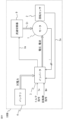
- FIG. 1 is a block diagram showing a system configuration of an electric vehicle according to a first embodiment.
- the electric vehicle 100 includes a motor which is a rotating electric machine 1 that drives the electric vehicle 100, a rotation sensor 2 provided on the rotating electric machine 1, an inverter 3 which drives and controls the rotating electric machine 1, and a battery 4 which supplies power to the inverter 3.
- the rotation sensor 2 may be a resolver, an encoder, a magneto resistive sensor (MR sensor), etc.
- the rotation sensor 2 acquires rotation speed information 2 a such as the angle or angular speed of the rotating electric machine 1 .
- the inverter 3 is connected to the battery 4, converts DC power from the battery 4 into AC power, and supplies it to the rotating electric machine 1.
- a current i of each phase (U phase, V phase, W phase) of the rotating electric machine 1 is detected, and each phase current i and rotation speed information 2 a from the rotation sensor 2 are fed back to the inverter 3.
- a torque command T* and a rotation speed command N* for the electric vehicle 100 are input to the inverter 3.
- the inverter 3 converts the DC power from the battery 4 into AC power and supplies a voltage and current due to the AC power to the rotating electric machine 1 to drive and control the rotating electric machine 1.
- the rotating electric machine 1 is driven in the power running region for more than half of the life cycle of the electric vehicle 100, that is, it is a drive motor that mainly performs power running. Further, the rotation direction of the rotating electric machine 1 when the electric vehicle 100 moves forward is defined as forward rotation.
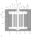
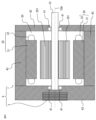
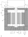
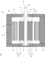
- FIG. 2 is a cross-sectional view showing a schematic configuration of the rotating electric machine 1, and shows a cross section cut along a plane passing through the axis of the rotating electric machine 1.
- the rotating electric machine 1 includes a cylindrical shaft 10, a cylindrical rotor 20 fixed to the shaft 10, and a cylindrical stator 30 arranged with a gap between them on the outside of the rotor 20.
- the rotor 20 and the stator 30 are arranged with an axis 10A as the center of a circle.
- the shaft 10 is rotatably supported by a bearing 41, the bearing 41 is fitted in a bracket 42, and the bracket 42 is fastened to a housing 43 by fastening elements such as screws.
- the stator 30 is fixed to the housing 43.
- the inside of the rotating electric machine 1 is filled with air 50, which is a fluid, and heat generated by the rotor 20 is dissipated through the air 50 inside the rotating electric machine 1 and through the shaft 10. In other words, the rotor 20 is cooled by heat transfer through the air 50 and the shaft 10.
- the stator 30 is an armature including a stator core 31 in which annular electromagnetic steel sheets are laminated in the axial direction, and coils 32 wound around each tooth (not shown) of the stator core 31. A plurality of teeth are provided at equal intervals in the circumferential direction.
- the coils 32 have coil portions disposed in slots of the stator core 31 and coil end portions protruding from the stator core 31 on both sides in the axial direction. For convenience, the coil portions disposed in the slots are omitted from FIG. 2 .
- the rotating electric machine 1 has a three-phase (U-phase, V-phase, W-phase) configuration
- the stator 30 has three-phase coils as the coils 32. Ends of the coils of each phase are connected to AC ends of the inverter 3.
- the stator 30 may be provided with multiple sets of three-phase coils (for example, two sets).
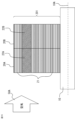
- FIG. 3 is a cross-sectional view showing the configuration of the rotor 20, and shows a schematic cross section taken along a plane passing through the axis 10A of the rotating electrical machine 1.
- FIG. 4 is a perspective view illustrating the configuration of one pole of the rotor 20.
- the rotor 20 includes a rotor core 21 and first and second permanent magnets 22A and 22B that are field magnets, and is configured with multiple stages (four stages in this case) of blocks 20A and 20B in the axial direction.
- the first block 20A on the axial end side includes the first permanent magnet 22A
- the second block 20B on the axial center side includes the second permanent magnet 22B.
- the first and second blocks 20A and 20B are skewed for each stage and stacked in the axial direction.
- the skew angle is set to a mechanical angle of ⁇ 360°/number of poles/reduced-order component/2 so as to cancel out the order components of the torque ripple that are to be reduced.
- the rotor 20 has eight poles, and is set to ⁇ 1.875° so as to reduce the 12th-order component.
- the positive rotation direction (arrow 60), which is the main rotation direction of the rotor 20, is the direction in which the rotor 20 rotates when the electric vehicle 100 moves forward, and is the counterclockwise direction as viewed from the front in Fig. 4.
- the positive direction of the skew angle is the positive rotation direction of the rotor 20.
- the first and second blocks 20A and 20B are set with symmetrical skew angles in the axial direction, with the skew angle of the first block 20A set to +1.875° and the skew angle of the second block 20B set to -1.875°.
- the first permanent magnet 22A is positioned +1.875° ahead of the rotor 20 in the forward rotation direction
- the second permanent magnet 22B is positioned -1.875° behind the rotor 20 in the forward rotation direction.
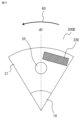
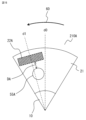
- FIG. 5 is a cross-sectional view showing the configuration of the first block 20A for one pole of the rotor 20, and shows a cross section perpendicular to the axial direction.
- the d-axis d1 of the first block 20A alone which is the line connecting the center of the first permanent magnet 22A and the center of rotation, is located at an angle ⁇ 1 (+1.875°) in the positive rotation direction of the rotor 20 (arrow 60) from the d-axis d0 of the rotor 20 as a whole.
- FIG. 6 is a cross-sectional view showing the configuration of the second block 20B for one pole of the rotor 20, and shows a cross section perpendicular to the axial direction.
- the d-axis d2 of the second block 20B alone which is the line connecting the center of the second permanent magnet 22B and the center of rotation, is positioned behind the d-axis d0 of the rotor 20 as a whole by ⁇ 2 (-1.875°) in the positive rotation direction of the rotor 20 (arrow 60).
- a vector D0 indicating the direction of the d-axis d0 of the entire rotor 20 is expressed by the following equation.
- D0 (L1/(L1+L2)) ⁇ D1+(L2/(L1+L2)) ⁇ D2
- L1 is the axial length of the first block 20A
- L2 is the axial length of the second block 20B
- D1 is a two-dimensional direction vector when d1 is projected onto a plane
- D2 is a two-dimensional direction vector when d2 is projected onto a plane.
- L1 L2
- d0 is located exactly halfway between d1 and d2.
- a certain advance angle ⁇ is generally set for the purpose of utilizing reluctance torque or for the purpose of flux weakening control. This advance angle is based on the q-axis q0 of the entire rotor 20. In the case of power running, ⁇ is in the range of 0° ⁇ 90°.
- Fig. 7 is a diagram showing the position of the field magnet in the first block 20A of the rotor 20 using electrical angles. As shown in Fig.
- the magnetic flux vector Q from the stator 30 has an advance angle ⁇ 0 based on the q-axis q0 of the rotor 20 as a whole, and an advance angle ⁇ 1 based on the q-axis q1 of the first block 20A.
- the d-axis d1 of the first block 20A is a position advanced from the d-axis d0 of the rotor 20 in the forward rotation direction of the rotor 20 (arrow 60).
- Fig. 8 is a diagram showing the position of the field magnet in the second block 20B of the rotor 20 using electrical angles.
- the magnetic flux vector Q from the stator 30 has an advance angle ⁇ 0 based on the q-axis q0 of the rotor 20 as a whole, and an advance angle ⁇ 2 based on the q-axis q2 of the second block 20B.
- the d-axis d2 of the second block 20B is a position that lags behind the d-axis d0 of the rotor 20 in the forward rotation direction of the rotor 20 (arrow 60).
- the advance angle ⁇ 0 is based on the q-axis q0 of the rotor 20 as a whole
- the advance angle ⁇ 2 based on the q-axis q2 of the second block 20B is greater than the advance angle ⁇ 1 based on the q-axis q1 of the first block 20A. That is, the advance angle of the second block 20B is closer to 90 degrees than that of the first block 20A, and the amount of magnetic flux weakening is greater.
- flux-weakening control when flux-weakening control is performed, iron loss generated in the rotor 20 is reduced, and the second block 20B generates less heat than the first block 20A. That is, the first block 20A generates more heat than the second block 20B.
- the first permanent magnet 22A generates more heat than the second permanent magnet 22B, so that the first permanent magnet 22A is a high heat generating magnet and the second permanent magnet 22B is a low heat generating magnet.
- the first block 20A is disposed at the axial end side, and the second block 20B is disposed at the axial center side.
- the first block 20A which generates a large amount of heat, is disposed at the axial end side, so that the contact area with the air 50 inside the rotating electric machine 1 is large, and heat is easily dissipated from the shaft end.
- the first block 20A is close to the end of the shaft 10, so heat is easily diffused to the outside air through the shaft 10. In this way, the heat dissipation of the first block 20A, which generates a large amount of heat, is made greater than that of the second block 20B, so that the temperature distribution is made uniform between the first block 20A and the second block 20B. This makes it possible to reduce the maximum temperature of the entire rotor 20, and to achieve a smaller size and higher output of the rotating electric machine 1.
- the heat generated by the rotor 20 is mainly from the first and second permanent magnets 22A and 22B, which are field magnets. In this case, making the heat dissipation of the first block 20A greater than that of the second block 20B is the same as making the heat dissipation of the first permanent magnet 22A greater than that of the second permanent magnet 22B.
- the first permanent magnet 22A is a high heat generation magnet and the second permanent magnet 22B is a low heat generation magnet, and the rotor 20 is cooled by heat transfer via a fluid, with the heat dissipation properties of the high heat generation magnet being greater than the heat dissipation properties of the low heat generation magnet.
- This improves the uniformity of the temperature distribution within the rotating electrical machine 1, thereby reducing the maximum temperature and enabling the rotating electrical machine 1 to be made smaller and have higher output.
- the rotor 20 has multiple stages of blocks arranged in the axial direction, each stage consisting of at least one first block 20A having a first permanent magnet 22A for each pole and at least one second block 20B having a second permanent magnet 22B for each pole, and of the multiple stages of blocks, the blocks having the high heat generating magnets are arranged at the axial end side, and the blocks having the low heat generating magnets are arranged at the axial center side. Therefore, the heat dissipation ability of the high heat generating magnets can be easily and reliably made greater than the heat dissipation ability of the low heat generating magnets, and the rotor 20 is effectively cooled.
- the rotor 20 is configured with four blocks in the axial direction, but the number of blocks may be other than four as long as the first block 20A is arranged at the axial end side and the second block 20B is arranged at the axial center side.
- the rotor 20 is cooled via the air 50 and the shaft 10, but the fluid is not limited to the air 50, and oil, for example, may be used.
- the second block 20B When the rotating electric machine 1 performs regenerative operation, the second block 20B, in which the second permanent magnet 22B is arranged at a position lagging in the forward rotation direction of the rotor 20, generates more heat than the first block 20A.
- the above-mentioned advance angle ⁇ is in the range of 0° ⁇ 90° during power running, whereas it is in the range of 90° ⁇ 180° during regenerative operation.
- the first block which is arranged at a phase-advanced position, has ⁇ closer to 90 degrees, which increases the amount of magnetic flux weakened and reduces the amount of heat generated. For this reason, the second block 20B generates more heat.
- the rotating electric machine 1 has been described as a drive motor that mainly performs power running operations, but the electric vehicle 100 may be provided with a rotating electric machine that functions as a generator in addition to the drive motor.
- the rotating electric machine 1 is a generator that mainly performs regenerative operations, it is configured as follows.
- the second block 20B in which the second permanent magnet 22B is arranged at a position delayed in the forward rotation direction of the rotor 20 generates a larger amount of heat than the first block 20A in which the first permanent magnet 22A is arranged at a position advanced in the forward rotation direction of the rotor 20.
- the second permanent magnet 22B generates a larger amount of heat than the first permanent magnet 22A, so that the second permanent magnet 22B is a high heat generating magnet and the first permanent magnet 22A is a low heat generating magnet.
- the second block 20B is disposed on the axial end side of the rotor 20, and the first block 20A is disposed on the axial center side. Note that the arrangement of the first block 20A and the second block 20B is reversed in Figures 3 and 4, and is not shown for convenience.
- the rotor 20 is cooled by heat transfer via the fluid, with the heat dissipation of the high heat generating magnet (second permanent magnet 22B) being greater than that of the low heat generating magnet (first permanent magnet 22A).
- second permanent magnet 22B the heat dissipation of the high heat generating magnet
- first permanent magnet 22A the low heat generating magnet
- FIG. 9 is a cross-sectional view showing the configuration of a rotor and a stator according to the second embodiment, and shows a schematic cross section taken along a plane passing through an axis 10A of the rotating electrical machine 1. As shown in FIG. As shown in FIG.
- stator core 31 of stator 30 which is arranged on the outside of rotor 20 with a gap therebetween, has teeth with different shapes between axial end regions 31A of stator core 31 and axial central region 31B sandwiched between axial end regions 31A on both sides.
- the stator core 31 protrudes toward the rotor 20, in this case having teeth protruding from the outer periphery to the inner periphery, and is stacked in the axial direction, with a plurality of teeth made up of stacked teeth portions spaced evenly apart in the circumferential direction.
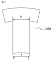
- FIG. 10 is a diagram showing the teeth portion of the axial end region 31A.
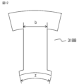
- FIG. 11 is a diagram showing the teeth portion in the axial center region 31B.
- the tip angle of the teeth 31AA in the axial end region 31A is x [°]
- the base width of the teeth 31AA is a [mm].
- the tip angle of the teeth 31BA in the axial center region 31B is y (>x) [°]
- the base width of the teeth 31BA is b (>a) [mm]. Note that the larger the tip angle, the larger the tip width.
- the tip width and base width of the teeth 31AA in the axial end region 31A are narrower than those of the teeth 31BA in the axial center region 31B, so that the width of the magnetic path of the teeth 31AA in the axial end region 31A is narrower than that of the teeth 31BA in the axial center region 31B, and magnetic saturation is more likely to occur.
- the axial end regions 31A of the stator 30 have less loss than the axial central region 31B.
- the magnetic flux passing from the teeth portions 31AA of the axial end regions 31A to the rotor 20 is reduced, and the loss occurring in the corresponding region of the rotor 20 is also reduced.
- the first block 20A with a high heat generation amount is arranged on the axial end side
- the second block 20B with a low heat generation amount is arranged on the axial center side in the rotor 20.
- the teeth 31AA in the axial end region 31A have narrower tip and base widths than the teeth 31BA in the axial center region 31B, but the same effect can be obtained if at least one of the tip and base widths is narrower.
- Fig. 12 is a diagram showing teeth portions in an axial center region 31B according to another example of embodiment 2.
- teeth portions 31AA shown in Fig. 10 are used in axial end regions 31A.
- the tip angle of the teeth 31BB in the axial center region 31B is z (>x) [°]
- the base width of the teeth 31BB is b (>a) [mm].
- the shape of the teeth 31BB is a so-called flanged shape, in which the width is wider only at the tip.
- the base width of the teeth 31BB may be the same as the base width of the teeth 31AA in the axial end region 31A.
- stator core 31 which combines multiple teeth 31AA, 31BB with different tip widths, is effective in reducing torque ripple and is particularly suitable for rotating electrical machines 1 that are operated in a manner that is sensitive to torque ripple.
- FIG. 13 is a cross-sectional view showing the configuration of a rotor according to the third embodiment, and shows a schematic cross section taken along a plane passing through an axis 10A of the rotating electrical machine 1. As shown in FIG.
- the rotor 200 includes a rotor core 21 and first and second permanent magnets 22A and 22B, and is cooled by a fluid 51, which is oil, flowing through a through hole 55 that penetrates in the axial direction.
- the rotor 200 is composed of a first block 200A on the upstream side of the fluid 51 in the axial direction, and a second block 200B on the downstream side, with the first block 200A including the first permanent magnet 22A and the second block 200B including the second permanent magnet 22B.
- FIG. 14 is a cross-sectional view showing the configuration of a first block 200A for one pole of the rotor 200, and shows a cross section perpendicular to the axial direction.
- FIG. 15 is a cross-sectional view showing the configuration of the second block 200B for one pole of the rotor 200, and shows a cross section perpendicular to the axial direction.
- the first block 200A includes a first permanent magnet 22A arranged at a position advanced in the forward rotation direction (arrow 60) of the rotor 200 for each pole, as in the first embodiment.
- the second block 200B includes a second permanent magnet 22B arranged at a position delayed in the forward rotation direction (arrow 60) of the rotor 200 for each pole, as in the first embodiment.
- a through hole 55 penetrating in the axial direction for each pole of the rotor 200 is provided on the d-axis d0 of the entire rotor 200.
- a certain advance angle is set based on the q-axis q0 of the rotor 200 as a whole, for the purpose of utilizing reluctance torque or flux weakening control.
- the advance angle based on the q-axis of the second block 200B is greater than the advance angle based on the q-axis of the first block 200A. That is, the advance angle of the second block 200B is closer to 90 degrees than the first block 200A, and the amount of flux weakening is greater, resulting in a lower amount of heat generation.
- the first permanent magnet 22A is a high heat generating magnet
- the second permanent magnet 22B is a low heat generating magnet.
- the rotating electric machine 1 is a drive motor that mainly performs power running, and the first block 200A, which generates a high amount of heat, is arranged upstream of the fluid 51 in the axial direction, and the second block 200B, which generates a low amount of heat, is arranged downstream.
- the fluid 51 flowing through the through hole 55 removes heat from the first block 200A and then removes heat from the second block 200B.
- the temperature of the fluid 51 in contact with the first block 200A is lower than the temperature of the fluid 51 in contact with the second block 200B, and the heat removal effect is high. This makes it possible to equalize the temperatures of the first block 200A and the second block 200B.
- the heat dissipation of the first block 200A which generates a large amount of heat, is made greater than that of the second block 200B, so that the temperature distribution is made uniform between the first block 200A and the second block 200B.
- making the heat dissipation properties of the first block 200A greater than that of the second block 200B is the same as making the heat dissipation properties of the first permanent magnet 22A greater than that of the second permanent magnet 22B.
- the rotating electric machine 1 has been described as a drive motor that mainly performs power running operations, but when the rotating electric machine 1 is a generator that mainly performs regenerative operations, it is configured as follows.
- the second permanent magnet 22B has a higher heat generation amount than the first permanent magnet 22A, so that the second permanent magnet 22B is a high heat generation magnet and the first permanent magnet 22A is a low heat generation magnet.
- the second block 200B which generates a high heat generation amount, is arranged upstream of the fluid 51 in the axial direction, and the first block 200A, which generates a low heat generation amount, is arranged downstream.
- the rotor 20 is cooled by heat transfer through the fluid 51, with the heat dissipation of the high heat generating magnet (second permanent magnet 22B) being greater than that of the low heat generating magnet (first permanent magnet 22A).
- second permanent magnet 22B the heat dissipation of the high heat generating magnet
- first permanent magnet 22A the low heat generating magnet
- Embodiment 4 Next, a fourth embodiment will be described with reference to the drawings.
- the rotor 200 is cooled by the fluid 51 flowing through the through holes 55 provided for each pole of the rotor 200.
- no through holes are provided, and the rotor is cooled by the fluid flowing in the axial direction within the rotating electric machine 1.
- 16 is a cross-sectional view showing the configuration of a rotor according to a fourth embodiment, and shows a schematic cross section cut along a plane passing through an axis 10A of the rotating electric machine 1.
- the rotating electric machine 1 will be described as a driving motor that mainly performs power running.
- the rotor 201 includes a rotor core 21 and first and second permanent magnets 22A and 22B, and is cooled by a fluid 50A, which is air flowing in the axial direction.
- the rotor 201 includes a first block 20A on the upstream side of the fluid 50A in the axial direction, and a second block 20B on the downstream side, with the first block 20A including the first permanent magnet 22A and the second block 20B including the second permanent magnet 22B.
- the configurations of the first and second blocks 20A, 20B are the same as those of the first embodiment (see Figs. 5 and 6).
- the first permanent magnet 22A is a high heat generating magnet
- the second permanent magnet 22B is a low heat generating magnet.
- the first block 20A which generates a high amount of heat
- the second block 20B which generates a low amount of heat
- the fluid 50A flowing in the axial direction first absorbs heat from the first block 20A, and then absorbs heat from the second block 20B.
- the temperature of the fluid 50A in contact with the first block 20A is lower than the temperature of the fluid 50A in contact with the second block 20B, and the heat extraction effect is high. This makes it possible to equalize the temperatures of the first block 20A and the second block 20B.
- the heat dissipation of the first block 20A which generates a large amount of heat, is made greater than that of the second block 20B, so that the temperature distribution is made uniform between the first block 20A and the second block 20B.
- This makes it possible to reduce the maximum temperature of the entire rotor 201, and to achieve a smaller size and higher output of the rotating electric machine 1.
- the rotating electric machine 1 is of a ventilation-cooling type, which does not require the provision of a separate through hole, it can be realized with a simple configuration.
- the rotating electric machine 1 has been described as a drive motor that mainly performs power running operations, but when the rotating electric machine 1 is a generator that mainly performs regenerative operations, it is configured as follows.
- the second permanent magnet 22B has a higher heat generation amount than the first permanent magnet 22A, so that the second permanent magnet 22B is a high heat generation magnet and the first permanent magnet 22A is a low heat generation magnet.
- the second block 20B which generates a high heat generation amount, is arranged upstream of the fluid 50A in the axial direction, and the first block 20A, which generates a low heat generation amount, is arranged downstream.
- the rotor 201 is cooled by heat transfer through the fluid 50A by making the heat dissipation of the high heat generating magnet (second permanent magnet 22B) greater than that of the low heat generating magnet (first permanent magnet 22A).
- This increases the uniformity of the temperature distribution within the rotating electric machine 1, reducing the maximum temperature and enabling the rotating electric machine 1 to be made smaller and with higher output.
- the fluids 51 and 50A used in the above third and fourth embodiments are not limited to oil or air, but may be any fluid with high heat transfer performance.
- FIG. 17 is a block diagram showing a system configuration of an electric vehicle according to the fifth embodiment.
- the electric vehicle 100A includes a motor which is a rotating electric machine 1 that drives the electric vehicle 100A, a rotation sensor 2 provided in the rotating electric machine 1, an inverter 3 which drives and controls the rotating electric machine 1, a battery 4 which supplies power to the inverter 3, and a flow path switch 5 provided in the rotating electric machine 1.
- the rotating electric machine 1, the rotation sensor 2, the inverter 3 and the battery 4 are the same as those described using FIG. 1 in the above-mentioned embodiment 1, but the configuration of the rotor within the rotating electric machine 1 is the same as that in the above-mentioned embodiment 3 or 4.
- the rotating electric machine 1 As described in the third embodiment, the rotor 200 is cooled by the fluid 51 flowing in the axial direction through the through hole 55.
- the flow path switch 5 reverses the direction of the fluid 51 when the rotating electric machine 1 switches between the power running operation and the regenerative operation.
- the flow path switch 5 has, for example, a solenoid-type directional control valve therein, and is operated by a switching command 3 a from the inverter 3.
- the inverter 3 provides a switching command 3a to the flow path switch 5, and the flow path switch 5 reverses the flow direction of the fluid 51.
- the fluid 51 flowing from the first block 200A toward the second block 200B during power running is reversed during regeneration, and flows from the second block 200B toward the first block 200A.
- the first block 200A is provided with a first permanent magnet 22A arranged at a position advanced in the forward rotation direction of the rotor 200 for each pole
- the second block 200B is provided with a second permanent magnet 22B arranged at a position delayed in the forward rotation direction of the rotor 200 for each pole.
- the first block 200A generates a larger amount of heat during power running
- the second block 200B generates a larger amount of heat during regeneration.
- the rotating electric machine 1 is provided with a flow path switch 5 that reverses the flow direction of the fluid 51, so that the fluid 51 flows from the first block 200A or the second block 200B, whichever generates more heat, to the block which generates less heat, not only during power running but also during regeneration.
- a flow path switch 5 that reverses the flow direction of the fluid 51, so that the fluid 51 flows from the first block 200A or the second block 200B, whichever generates more heat, to the block which generates less heat, not only during power running but also during regeneration.
- the rotating electric machine 1 according to the above embodiment 3 was used, but the rotating electric machine 1 according to the above embodiment 4 can also be used in the same way.
- the inverter 3 gives a switching command 3a to the flow path switch 5, and the flow path switch 5 reverses the flow direction of the fluid 50A.
- the fluid 50A that flows from the first block 20A to the second block 20B during power running is reversed during regeneration and flows from the second block 20B to the first block 20A. Therefore, the rotor 201 can be effectively cooled not only during power running but also during regeneration.
- the flow path switch 5 is not limited to being operated by commands from the inverter 3, but may be switched based on other information, for example, the current value or angular velocity information of the rotating electric machine 1.
- the fifth embodiment can also be applied to a rotating electric machine 1 that is a generator that mainly performs regenerative operation.
- the second permanent magnet 22B is a high heat generating magnet
- the first permanent magnet 22A is a low heat generating magnet
- the second block 20B with a high heat generation amount is arranged upstream of the fluid 50A in the axial direction
- the first block 20A with a low heat generation amount is arranged downstream.
- the flow path switch 5 reverses the flow direction of the fluid 50A.
- the fluid 50A that flows from the second block 20B to the first block 20A during regeneration is reversed during power running and flows from the first block 20A to the second block 20B. Therefore, the rotor 201 can be effectively cooled not only during regeneration but also during power running.
- FIG. 18 is a cross-sectional view showing the configuration of a first block 210A for one pole of the rotor 200, and shows a cross section perpendicular to the axial direction.
- FIG. 19 is a cross-sectional view showing the configuration of the second block 210B for one pole of the rotor 200, and shows a cross section perpendicular to the axial direction.
- the rotor 200 includes a rotor core 21 and first and second permanent magnets 22A and 22B, and is cooled by a fluid 51, which is oil, flowing through a through hole 55A that penetrates in the axial direction.
- the rotor 200 is composed of a first block 210A on the upstream side of the fluid 51 in the axial direction, and a second block 210B on the downstream side, with the first block 210A including the first permanent magnet 22A and the second block 210B including the second permanent magnet 22B.
- the first block 210A includes a first permanent magnet 22A arranged at a position advanced in the forward rotation direction (arrow 60) of the rotor 200 for each pole.
- the second block 210B includes a second permanent magnet 22B arranged at a position delayed in the forward rotation direction (arrow 60) of the rotor 200 for each pole.
- a through hole 55A penetrating in the axial direction is provided for each pole of the rotor 200.
- the through hole 55A is disposed on the d-axis d1 side of the first block 210A with respect to the d-axis d0 of the rotor 200. That is, the through hole 55A is provided at a position where a distance DA from the through hole 55A to the first permanent magnet 22A is shorter than a distance DB from the through hole 55A to the second permanent magnet 22B.
- the ratio of the distance DA to the distance DB is the inverse ratio of the heat generation amounts of the first and second permanent magnets 22A and 22B.
- the through hole 55A penetrating in the axial direction is provided at a position closer to the first permanent magnet 22A, which is a high heat generating magnet, than to the second permanent magnet 22B, which is a low heat generating magnet.
- the first block 210A which generates a large amount of heat, can dissipate heat more effectively than the second block 210B, which generates a small amount of heat, and the temperature distribution is uniform between the first block 210A and the second block 210B. This makes it possible to reduce the maximum temperature of the entire rotor 200, and to achieve a smaller size and higher output of the rotating electric machine 1.
- the first block 210A is arranged on the upstream side of the fluid 51, and the second block 210B is arranged on the downstream side. This, together with the effect of the arrangement of the through holes 55A, further improves the heat dissipation of the first block 210A, which has a high heat generation amount, and reduces the maximum temperature of the entire rotor 200.
- the arrangement of the first block 210A and the second block 210B is not limited to the above embodiment, and may be the same as in the above embodiment 1, or the first block 210A and the second block 210B may be arranged alternately in a total of four stages. Even in these cases, by providing the through hole 55A at a position closer to the first permanent magnet 22A than the second permanent magnet 22B, the heat dissipation of the first permanent magnet 22A becomes greater than that of the second permanent magnet 22B, and the maximum temperature of the entire rotor 200 can be reduced.
- the fluid 51 is not limited to oil or air, but may be any fluid with high heat transfer performance.
- the sixth embodiment can also be applied to a rotating electric machine 1 that is a generator that mainly performs regenerative operations.
- the second permanent magnet 22B is a high heat generating magnet
- the first permanent magnet 22A is a low heat generating magnet
- the second block 210B with a high heat generation amount is arranged upstream of the fluid 51 in the axial direction
- the first block 210A with a low heat generation amount is arranged downstream.
- a through hole 55A that penetrates in the axial direction is provided for each pole of the rotor 200.
- the through hole 55A is arranged on the d-axis d2 side of the second block 210B with respect to the d-axis d0 of the rotor 200, that is, the through hole 55A is provided at a position where the distance from the through hole 55A to the second permanent magnet 22B is shorter than the distance from the through hole 55A to the first permanent magnet 22A.
- the heat dissipation of the second permanent magnet 22B is greater than that of the first permanent magnet 22A (low heat generating magnet), and the maximum temperature of the entire rotor 200 can be reduced.
- FIG. 20 is a cross-sectional view showing a schematic configuration of a rotating electric machine unit according to embodiment 7, and shows a cross section cut along a plane passing through the axis of the rotating electric machine 1.
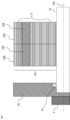
- Fig. 21 is a partial detailed view of Fig. 20, and shows a schematic cross section.
- the rotating electric machine unit 6 has a structure in which the rotating electric machine 1 and the inverter 3 that drives the rotating electric machine 1 are integrated together, and the inverter 3 is disposed on one shaft end side of the rotating electric machine 1 .
- the rotating electric machine 1 uses a rotor 201 in which a first block 20A and a second block 20B are arranged in two stages in the axial direction.
- the configuration of the rotating electric machine 1 other than the rotor 201 is the same as that of the above-mentioned embodiment 1 shown in FIG. 2.
- the configurations of the first and second blocks 20A and 20B are also the same as those of the above-mentioned embodiment 1 (see FIG. 5 and FIG. 6), with the first block 20A comprising a first permanent magnet 22A and the second block 20B comprising a second permanent magnet 22B.
- the inverter 3 is disposed on the shaft end side close to the second block 20B which generates a low amount of heat.
- the first block 20A which generates a high amount of heat is disposed at a position away from the inverter 3, and the second block 20B which generates a low amount of heat is disposed at a position close to the inverter 3.
- the rotating electric machine 1 When the rotating electric machine 1 is driven, heat is generated not only from the rotating electric machine 1 side but also from the inverter 3.
- the first block 20A which generates a large amount of heat, is disposed at a position away from the inverter 3, so that the thermal effect from the inverter 3 to the first block 20A can be reduced.
- the heat dissipation of the first permanent magnet 22A is greater than that of the second permanent magnet 22B (low heat generating magnet), and the temperature distribution in the first block 20A and the second block 20B is made uniform, thereby reducing the maximum temperature of the entire rotor 201.
- the first block 20A may be placed upstream and the second block 20B may be placed downstream, and the cooling fluid 50A may be caused to flow in the axial direction, which will further improve the uniformity of the temperature distribution.
- a rotor 200 having through holes 55, 55A may be used to allow the cooling fluid 50A to flow in the axial direction.
- the thermal effect from the inverter 3 on the first blocks 200A, 210A can be reduced, and the temperature distribution can be further uniformed.
- FIG. 22 is a cross-sectional view showing a schematic configuration of a rotating electric machine unit according to an eighth embodiment, taken along a plane passing through the axis of the rotating electric machine 1.
- Fig. 23 is a partial detailed view of Fig. 22, and shows the cross-section in a schematic manner.
- the rotating electric machine unit 8 has a structure including a rotating electric machine 1 and a reducer 7 connected to a shaft 10 of the rotating electric machine 1 to adjust the rotational speed, and the reducer 7 is arranged on one axial end side of the rotating electric machine 1.
- the rotating electric machine 1 uses a rotor 201 in which a first block 20A and a second block 20B are arranged in two stages in the axial direction.
- the configuration of the rotating electric machine 1 other than the rotor 201 is the same as that of the above-mentioned embodiment 1 shown in FIG. 2.
- the configurations of the first and second blocks 20A and 20B are also the same as those of the above-mentioned embodiment 1 (see FIG. 5 and FIG. 6), with the first block 20A comprising a first permanent magnet 22A and the second block 20B comprising a second permanent magnet 22B.
- the reducer 7 is disposed on the shaft end side close to the second block 20B which generates a low amount of heat.
- the first block 20A which generates a high amount of heat is disposed at a position away from the reducer 7, and the second block 20B which generates a low amount of heat is disposed at a position close to the reducer 7.
- the rotating electric machine 1 When the rotating electric machine 1 is driven, heat is generated not only from the rotating electric machine 1 side but also from the reduction gear 7.
- the first block 20A which generates a large amount of heat, is disposed at a position away from the reduction gear 7, so that the thermal effect from the reduction gear 7 to the first block 20A can be reduced.
- the heat dissipation of the first permanent magnet 22A is greater than that of the second permanent magnet 22B (low heat generating magnet), and the temperature distribution in the first block 20A and the second block 20B is made uniform, thereby reducing the maximum temperature of the entire rotor 201.
- the first block 20A may be placed upstream and the second block 20B may be placed downstream, and the cooling fluid 50A may be caused to flow in the axial direction, which will further improve the uniformity of the temperature distribution.
- a rotor 200 having through holes 55, 55A may be used to allow the cooling fluid 50A to flow in the axial direction.
- the thermal effect from the inverter 3 on the first blocks 200A, 210A can be reduced, and the temperature distribution can be further uniformed.
- the rotating electric machine 1 is described as a driving motor that mainly performs power running, but the present invention can also be applied to a rotating electric machine 1 that is a generator that mainly performs regenerative operation.
- the second permanent magnet 22B is a high heat generating magnet
- the first permanent magnet 22A is a low heat generating magnet
- the second block 20B that generates a high amount of heat is arranged upstream of the fluid 50A in the axial direction
- the first block 20A that generates a low amount of heat is arranged downstream.
- the inverter 3 (or the reducer 7) that generates heat is arranged on the axial end side close to the first block 20A that generates a low amount of heat.
- the second block 20B that generates a high amount of heat is arranged at a position away from the inverter 3 (or the reducer 7), and the first block 20A that generates a low amount of heat is arranged at a position close to the inverter 3 (or the reducer 7).
- the temperature distribution in the first block 20A and the second block 20B is made uniform, and the maximum temperature of the entire rotor 201 can be reduced.
- Embodiment 9 Next, a ninth embodiment will be described with reference to the drawings.
- the rotating electric machine 1 will be described as a driving motor that mainly performs power running.
- the rotors 20, 200, 201 having a plurality of stages of blocks in the axial direction are used, but in this embodiment, a single structure is used in the axial direction.
- 24 is a cross-sectional view showing the configuration of a rotor according to the ninth embodiment, and shows a schematic cross section taken along a plane passing through the axis 10A of the rotating electric machine 1.
- FIG. 25 is a cross-sectional view showing the configuration for one rotor pole, and shows a cross section perpendicular to the axial direction.
- the rotor 220 comprises a rotor core 21 and first and second permanent magnets 22A and 22B, and is cooled by a fluid 51, which is oil, flowing through a through hole 55A that penetrates in the axial direction.
- the rotor 220 comprises a first permanent magnet 22A arranged at a forward position in the forward rotation direction (arrow 60) of the rotor 220, a second permanent magnet 22B arranged at a delayed position, and a through hole 55A through which the fluid 51 flows, for each pole.
- the first permanent magnet 22A and the second permanent magnet 22B are arranged symmetrically or approximately symmetrically with respect to the d-axis d0 of the rotor 220.
- the through hole 55A is arranged on the first permanent magnet 22A side with respect to the d-axis d0 of the rotor 220. In other words, the through hole 55A is provided at a position where the distance DA from the through hole 55A to the first permanent magnet 22A is shorter than the distance DB from the through hole 55A to the second permanent magnet 22B.
- FIG. 26 is a diagram showing the field magnet positions in rotor 220 using electrical angles.
- the rotating electric machine 1 when operated in power running, it is operated with a constant advance angle ⁇ (0° ⁇ 90°) based on the q-axis q0 in order to utilize reluctance torque or perform flux weakening control.
- the magnetic flux vector Q from the stator 30 has an advance angle ⁇ 0 based on the q-axis q0 of the rotor 220.
- the first permanent magnet 22A is disposed at a position advanced in the forward rotation direction (arrow 60)
- the second permanent magnet 22B is disposed at a position delayed in the forward rotation direction (arrow 60).
- the second permanent magnet 22B When the rotor 220 is driven with an advance angle ⁇ 0, the second permanent magnet 22B is more strongly affected by weakening the field magnetic flux than the first permanent magnet 22A. Therefore, the second permanent magnet 22B and the rotor core 21 around it generate less heat than the first permanent magnet 22A and the rotor core 21 around it. In other words, the first permanent magnet 22A generates more heat than the second permanent magnet 22B, making the first permanent magnet 22A a high heat magnet and the second permanent magnet 22B a low heat magnet.
- the heat transfer from the first and second permanent magnets 22A and 22B to the fluid 51 increases the closer they are to the fluid 51.
- the first permanent magnet 22A which is closer to the through hole 55A through which the fluid 51 flows, is more likely to extract heat than the second permanent magnet 22B, and has higher heat dissipation properties.
- a first permanent magnet 22A and a second permanent magnet 22B are provided on each pole of the rotor 220, and further, a through hole 55A for flowing a fluid 51 in the axial direction is provided for each pole at a position closer to the first permanent magnet 22A (high heat generation magnet) than to the second permanent magnet 22B (low heat generation magnet). Therefore, the heat generated by the first permanent magnet 22A is more likely to escape into the fluid 51 flowing through the through hole 55A than the heat generated by the second permanent magnet 22B, and the heat dissipation property of the first permanent magnet 22A is greater than that of the second permanent magnet 22B.
- the first permanent magnet 22A which has a higher heat generation amount, can have greater heat dissipation properties than the second permanent magnet 22B, which has a lower heat generation amount, making the temperature distribution in the rotor 220 more uniform and reducing the maximum temperature, thereby enabling the rotating motor 1 to be made smaller and more powerful.
- the through holes 55A are provided at a position that does not interfere with the magnetic circuit, and it is preferable that the distances DA, DB between the first and second permanent magnets 22A, 22B and the through holes 55A are selected so that the through holes 55A do not interfere with the magnetic circuit.
- the through holes 55A are provided at a position where the distance DA is as small as possible within the region where the magnetic flux density of the rotor core 21 is 0.1 [T] or less if the through holes 55A are not provided.
- the ratio of the distance DA to the distance DB may be set to the inverse ratio of the heat generation amounts of the first and second permanent magnets 22A and 22B.
- the rotating electric machine 1 is described as a driving motor that mainly performs power running, but the present invention can also be applied to a rotating electric machine 1 that is a generator that mainly performs regenerative operation.
- the second permanent magnet 22B is a high heat generating magnet
- the first permanent magnet 22A is a low heat generating magnet
- the through hole 55A is disposed on the second permanent magnet 22B side with respect to the d-axis d0 of the rotor 220. That is, the through hole 55A is disposed at a position where the distance from the through hole 55A to the second permanent magnet 22B is shorter than the distance from the through hole 55A to the first permanent magnet 22A.
- the second permanent magnet 22B which has a higher heat generation amount, can have greater heat dissipation properties than the first permanent magnet 22A, which has a lower heat generation amount, making the temperature distribution in the rotor 220 more uniform and reducing the maximum temperature, thereby enabling the rotating motor 1 to be made smaller and more powerful.
- FIG. 27 is a cross-sectional view showing the configuration of a rotor according to the tenth embodiment, and shows a schematic cross section taken along a plane passing through the axis 10A of the rotating electric machine 1.
- the rotor 230 similarly to the above-mentioned ninth embodiment, has a single structure in the axial direction.
- the rotor 230 has, for each pole, a first permanent magnet 22A arranged at an advanced position in the forward rotation direction (arrow 60) of the rotor 230, a second permanent magnet 22B arranged at a delayed position, and a first through hole 55B and a second through hole 55C through which the fluid 51 flows.
- the first permanent magnet 22A and the second permanent magnet 22B are arranged symmetrically or approximately symmetrically with respect to the d axis d0 of the rotor 230.
- the first through hole 55B is arranged on the first permanent magnet 22A side with respect to the d axis d0 of the rotor 230, and the second through hole 55C is arranged on the second permanent magnet 22B side with respect to the d axis d0 of the rotor 230.
- the first through hole 55B and the second through hole 55C are disposed symmetrically or approximately symmetrically with respect to the d-axis d0 of the rotor 230.
- the fluid 51 for cooling the rotor 230 flows through the first through hole 55B and the second through hole 55C in the same axial direction, but the speed at which the fluid flows through the first through hole 55B is set to be greater than the speed at which the fluid flows through the second through hole 55C.
- the first permanent magnet 22A generates more heat than the second permanent magnet 22B, so that the first permanent magnet 22A is a high heat generating magnet and the second permanent magnet 22B is a low heat generating magnet.
- each pole of the rotor 230 is provided with a first permanent magnet 22A and a second permanent magnet 22B, and further, a first through hole 55B and a second through hole 55C for flowing fluid 51 in the axial direction are provided for each pole.
- the flow speed of the fluid 51 flowing in the axial direction is set to be faster through the first through hole 55B than through the second through hole 55C.
- the fluid 51 flows at high speed through the first through hole 55B, which is positioned near the first permanent magnet 22A (high heat generating magnet) that has a high heat generation, and flows at low speed through the second through hole 55C, which is positioned near the second permanent magnet 22B (low heat generating magnet) that has a low heat generation.
- the first permanent magnet 22A Since heat transfer from a solid to a fluid increases as the flow rate increases, the heat generated by the first permanent magnet 22A is more likely to escape into the fluid 51 than the heat generated by the second permanent magnet 22B, and the heat dissipation ability of the first permanent magnet 22A is greater than that of the second permanent magnet 22B. In this way, the first permanent magnet 22A, which has a higher heat generation amount, can have greater heat dissipation properties than the second permanent magnet 22B, which has a lower heat generation amount, making the temperature distribution in the rotor 230 more uniform and reducing the maximum temperature, thereby enabling the rotating motor 1 to be made smaller and more powerful.
- the rotor 230 can be made symmetrical with respect to the d-axis d0, making it easy to design the magnetic circuit.
- the method of setting the positions of the first and second through holes 55B and 55C is not limited as long as they are symmetrical with respect to the d-axis d0 of the rotor 230.
- a flux barrier on the magnetic circuit can be used as the first and second through holes 55B and 55C.
- the rotating electric machine 1 is described as a driving motor that mainly performs a power running operation, but the present invention can also be applied to a rotating electric machine 1 that is a generator that mainly performs a regenerative operation.
- the second permanent magnet 22B is a high heat generating magnet
- the first permanent magnet 22A is a low heat generating magnet
- the flow rate of the fluid 51 flowing in the axial direction through the second through hole 55C is set to be higher than the flow rate through the first through hole 55B.
- the fluid 51 flows at high speed through the second through hole 55C arranged near the second permanent magnet 22B (high heat generating magnet) that generates a high amount of heat, and flows at low speed through the first through hole 55B arranged near the first permanent magnet 22A (low heat generating magnet) that generates a low amount of heat.
- the second permanent magnet 22B which has a higher heat generation amount, can have greater heat dissipation properties than the first permanent magnet 22A, which has a lower heat generation amount, making the temperature distribution in the rotor 230 more uniform and reducing the maximum temperature, thereby enabling the rotating motor 1 to be made smaller and more powerful.
- Fig. 28 is a block diagram showing a system configuration of an electric vehicle according to another example of embodiment 10.
- an electric vehicle 100B includes a rotating electric machine 1, a rotation sensor 2, an inverter 3, a battery 4, and further includes a flow rate switch 9 provided in the rotating electric machine 1.
- the flow rate switch 9 inverts the magnitude relationship between the speed of the fluid 51 flowing through the first through hole 55B and the speed of the fluid 51 flowing through the second through hole 55C when the rotating electric machine 1 switches between a power running operation and a regenerative operation.
- the inverter 3 provides a switching command 3a to the flow rate switch 9, and the flow rate switch 9 reduces the flow rate of the fluid 51 flowing through the first through hole 55B and increases the flow rate of the fluid 51 flowing through the second through hole 55C.
- the flow rate switch 9 switches the flow rate of the fluid 51 flowing through the first through hole 55B so that the flow rate of the fluid 51 flowing through the first through hole 55B is smaller than the flow rate of the fluid 51 flowing through the second through hole 55C.
- the rotor 230 can be effectively cooled during both power running and regeneration operations, so the rotor 230 can be cooled equally effectively whether the main operation of the rotating electric machine 1 is power running, regeneration, or both operations are performed to the same extent.
- FIG. 29 is a cross-sectional view showing a schematic configuration of a rotating electric machine 1A, showing a cross section cut along a plane passing through the axis of the rotating electric machine 1A.
- the rotating electric machine 1A includes a cylindrical shaft 10, a cylindrical rotor 20, and a cylindrical stator 30 arranged with a gap inside the rotor 20.
- the rotor 20 and the stator 30 are arranged with an axis 10A as the center of a circle.
- the shaft 10 is rotatably supported by a bearing 41, the bearing 41 is fitted into a bracket 42, and the bracket 42 is fastened to a housing 43 by a fastening element such as a screw.
- the stator 30 is an armature including a stator core 31 and coils 32 wound around each tooth (not shown) of the stator core 31 .
Landscapes
- Engineering & Computer Science (AREA)
- Power Engineering (AREA)
- Permanent Field Magnets Of Synchronous Machinery (AREA)
Abstract
回転電機(1)は、第1永久磁石(22A)と、第2永久磁石(22B)とを、各極毎に有したロータ(20)と、ステータコア(31)および巻線(32)を有してロータ(20)と空隙を介して配置されたステータ(30)とを備える。第1永久磁石(22A)は、ロータ(20)のd軸(d0)に対してロータ(20)の正回転方向に進んだ位置に配置され、第2永久磁石(22B)は遅れた位置に配置される。そして、回転電機(1)の動作に応じて発熱する第1永久磁石(22A)と第2永久磁石(22B)との発熱レベルの違いに基づいて、第1、第2永久磁石(22A,22B)の一方を高発熱磁石、他方を低発熱磁石とし、ロータ(20)は、前記高発熱磁石の放熱性を前記低発熱磁石の放熱性よりも大きくして、流体(50)を介した伝熱により冷却される。
Description
本願は、回転電機、回転電機ユニットおよび電動車両に関するものである。
電動車両用回転電機は小型高出力化が求められており、回転電機内の温度分布の均一性を高めて最高温度を低減する事が効果的である。また、電動車両用回転電機には高トルク化を目的として、ロータに永久磁石を有する永久磁石型同期電動機(PMSM)がしばしば用いられる。
特許文献1記載の従来技術による回転電機では、ステータコアにコイル素線が巻回されたコイルにおいて、該コイルからの放熱経路で放熱し易い部位の前記コイル素線の発熱量を大きく、かつ、該コイルからの放熱経路で放熱し難い部位の前記コイル素線の発熱量を小さく構成する。これにより、コイル内部の温度分布差を小さくでき、コイルの最高温度を低減できる。
上記特許文献1記載の従来技術では、コイル素線の断面積の大小でコイル内部の温度分布を調整するもので、永久磁石を有するロータの温度分布の均一性を高めることはできない。
本願は、上記のような課題を解決するための技術を開示するものであり、ロータに永久磁石を有した回転電機において、回転電機内の温度分布の均一性を高めて最高温度を低減し、小型高出力化を図ることを目的とする。さらに、このような回転電機を備えた回転電機ユニットおよび電動車両を提供する事を目的とする。
本願に開示される回転電機は、少なくとも1つの第1永久磁石と、少なくとも1つの第2永久磁石とを、各極毎に有した円筒状のロータと、ステータコアおよび巻線を有し該ロータと空隙を介して配置された円筒状のステータとを備える。前記第1永久磁石は、前記ロータのd軸に対して前記ロータの正回転方向に進んだ位置に配置され、前記第2永久磁石は、前記ロータの前記d軸に対して前記ロータの正回転方向に遅れた位置に配置される。そして、前記回転電機の動作に応じて発熱する前記第1永久磁石と前記第2永久磁石との発熱レベルの違いに基づいて、前記第1、第2永久磁石の一方を高発熱磁石、他方を低発熱磁石とし、前記ロータは、前記高発熱磁石の放熱性を前記低発熱磁石の放熱性よりも大きくして、流体を介した伝熱により冷却される。
また、本願に開示される回転電機ユニットは、前記回転電機と、該回転電機を駆動制御するインバータとを備え、前記ロータは、各極毎に前記第1永久磁石を備える第1ブロックと、各極毎に前記第2永久磁石を備える第2ブロックとを軸方向に配列して備え、前記インバータは、前記回転電機の一方の軸端側であって、前記第1、第2ブロックの内、前記低発熱磁石を備えるブロックに近い側に配設される。
また、本願に開示される回転電機ユニットは、前記回転電機と、該回転電機に接続される減速機とを備え、前記ロータは、各極毎に前記第1永久磁石を備える第1ブロックと、各極毎に前記第2永久磁石を備える第2ブロックとを軸方向に配列して備え、前記減速機は、前記回転電機の一方の軸端側であって、前記第1、第2ブロックの内、前記低発熱磁石を備えるブロックに近い側に配設される。
さらに、本願に開示される電動車両は、前記回転電機を備えて駆動され、前記ロータの正回転が主たる回転方向であって、前記電動車両が前進する際の回転方向である。
本願に開示される回転電機によれば、ロータに永久磁石を有した回転電機であって、回転電機内の温度分布の均一性を高めて最高温度を低減し、小型高出力化を図れる。
また、このような回転電機を備えた回転電機ユニットおよび電動車両を実現することができる。
また、このような回転電機を備えた回転電機ユニットおよび電動車両を実現することができる。
実施の形態1.
以下、実施の形態1について、図を参照して説明する。
図1は、実施の形態1による電動車両のシステム構成を示すブロック図である。
図1に示すように、電動車両100は、電動車両100を駆動する回転電機1であるモータと、回転電機1に設けられた回転センサ2と、回転電機1を駆動制御するインバータ3と、インバータ3に電力供給するバッテリ4とを備える。
回転センサ2には、レゾルバ、エンコーダ、MRセンサ(Magnetro Resistive Sensor)等が用いられる。回転センサ2は、回転電機1の角度あるいは角速度などの回転速度情報2aを取得する。
以下、実施の形態1について、図を参照して説明する。
図1は、実施の形態1による電動車両のシステム構成を示すブロック図である。
図1に示すように、電動車両100は、電動車両100を駆動する回転電機1であるモータと、回転電機1に設けられた回転センサ2と、回転電機1を駆動制御するインバータ3と、インバータ3に電力供給するバッテリ4とを備える。
回転センサ2には、レゾルバ、エンコーダ、MRセンサ(Magnetro Resistive Sensor)等が用いられる。回転センサ2は、回転電機1の角度あるいは角速度などの回転速度情報2aを取得する。
インバータ3は、バッテリ4と接続され、バッテリ4からの直流電力を交流電力に変換して回転電機1に供給する。回転電機1の各相(U相、V相、W相)の電流iは検出され、この各相電流iと、回転センサ2からの回転速度情報2aとは、インバータ3にフィードバックされる。
また、インバータ3には、電動車両100に対するトルク指令T*および回転数指令N*が入力される。そして、インバータ3は、トルク指令T*および回転数指令N*と、各相電流iおよび回転速度情報2aとに基づいて、バッテリ4からの直流電力を交流電力に変換して、回転電機1に交流電力による電圧および電流を供給して回転電機1を駆動制御する。
また、インバータ3には、電動車両100に対するトルク指令T*および回転数指令N*が入力される。そして、インバータ3は、トルク指令T*および回転数指令N*と、各相電流iおよび回転速度情報2aとに基づいて、バッテリ4からの直流電力を交流電力に変換して、回転電機1に交流電力による電圧および電流を供給して回転電機1を駆動制御する。
なお、この実施の形態では、回転電機1は、電動車両100のライフサイクルのうち半分以上の時間、力行領域で駆動される、即ち、主として力行動作を行う駆動用モータである。
また、電動車両100が前進する際の、回転電機1の回転方向を正回転とする。
また、電動車両100が前進する際の、回転電機1の回転方向を正回転とする。
図2は、回転電機1の概略構成を示す断面図であり、回転電機1の軸心を通る平面で切断した断面を示す。
図に示すように、回転電機1は、円柱状のシャフト10と、シャフト10に対して固定された円筒状のロータ20と、ロータ20の外側に空隙を介して配置された円筒状のステータ30とを備える。ロータ20およびステータ30は、軸心10Aを同一円心として配置される。
シャフト10は軸受41により回転可能に支持され、軸受41はブラケット42に嵌合しており、ブラケット42はハウジング43とネジなどの締結要素によって締結されている。ステータ30はハウジング43に固定される。
図に示すように、回転電機1は、円柱状のシャフト10と、シャフト10に対して固定された円筒状のロータ20と、ロータ20の外側に空隙を介して配置された円筒状のステータ30とを備える。ロータ20およびステータ30は、軸心10Aを同一円心として配置される。
シャフト10は軸受41により回転可能に支持され、軸受41はブラケット42に嵌合しており、ブラケット42はハウジング43とネジなどの締結要素によって締結されている。ステータ30はハウジング43に固定される。
回転電機1の内部は流体である空気50で満たされており、ロータ20の発熱は回転電機1内の空気50、およびシャフト10を介して放熱される。即ち、空気50およびシャフト10を介した伝熱によりロータ20は冷却される。
ステータ30は、円環板状の電磁鋼板が軸方向に積層されたステータコア31と、ステータコア31の各ティース(図示せず)に巻装されたコイル32とを備える電機子である。ティースは、周方向に均等間隔で複数備えられている。コイル32は、ステータコア31のスロット内に配置されたコイル部分と、ステータコア31から軸方向両側に突出したコイルエンド部とを有する。図2では、スロット内に配置されたコイル部分の図示は、便宜上省略する。
この場合、回転電機1は3相(U相、V相、W相)構成であり、ステータ30は、コイル32として3相のコイルを有する。各相コイルの端部は、インバータ3の交流端に接続される。なお、ステータ30には、3相のコイルを複数組(例えば、2組)設けてもよい。
この場合、回転電機1は3相(U相、V相、W相)構成であり、ステータ30は、コイル32として3相のコイルを有する。各相コイルの端部は、インバータ3の交流端に接続される。なお、ステータ30には、3相のコイルを複数組(例えば、2組)設けてもよい。
図3は、ロータ20の構成を示す断面図であり、回転電機1の軸心10Aを通る平面で切断した断面を模式的に示す。
図4は、ロータ20の1極分の構成を説明する斜視図である。
図3および図4に示すように、ロータ20は、ロータコア21と界磁磁石である第1、第2永久磁石22A、22Bとを備えて、軸方向に複数段(この場合、4段)のブロック20A、20Bで構成される。複数段のブロック20A、20Bの内、軸方向端部側の第1ブロック20Aは第1永久磁石22Aを備え、軸方向中央側の第2ブロック20Bは第2永久磁石22Bを備える。
図4は、ロータ20の1極分の構成を説明する斜視図である。
図3および図4に示すように、ロータ20は、ロータコア21と界磁磁石である第1、第2永久磁石22A、22Bとを備えて、軸方向に複数段(この場合、4段)のブロック20A、20Bで構成される。複数段のブロック20A、20Bの内、軸方向端部側の第1ブロック20Aは第1永久磁石22Aを備え、軸方向中央側の第2ブロック20Bは第2永久磁石22Bを備える。
第1、第2ブロック20A、20Bは、段ごとにスキューして軸方向に積み上げ成形されている。スキュー角度はトルクリプルのうち低減させたい次数成分を打ち消し合うように、機械角で(±360°/極数/低減次数成分/2)に設定される。この場合、ロータ20は8極であり、12次成分を低減するように、±1.875°に設定される。
ロータ20の主たる回転方向である正回転方向(矢印60)は、電動車両100が前進するときにロータ20が回転する方向であり、図4では、手前から見て反時計回りの方向である。スキュー角の正方向は、ロータ20の正回転方向である。
ロータ20の主たる回転方向である正回転方向(矢印60)は、電動車両100が前進するときにロータ20が回転する方向であり、図4では、手前から見て反時計回りの方向である。スキュー角の正方向は、ロータ20の正回転方向である。
第1、第2ブロック20A、20Bは、軸方向に対してスキュー角が対称になるように、第1ブロック20Aのスキュー角は+1.875°に、第2ブロック20Bのスキュー角は-1.875°に設定される。このように、第1永久磁石22Aは、ロータ20の正回転方向に+1.875°進んだ位置に配置され、第2永久磁石22Bは、ロータ20の正回転方向に-1.875°遅れた位置に配置される。
図5は、ロータ20の1極分の第1ブロック20Aの構成を示す断面図であり、軸方向に垂直な断面を示す。
図5に示すように、第1永久磁石22Aの中心と回転中心とを結ぶ線である、第1ブロック20A単体のd軸d1は、ロータ20全体としてのd軸d0から、ロータ20の正回転方向(矢印60)にθ1(+1.875°)で進んだ位置となる。
図6は、ロータ20の1極分の第2ブロック20Bの構成を示す断面図であり、軸方向に垂直な断面を示す。
図6に示すように、第2永久磁石22Bの中心と回転中心とを結ぶ線である、第2ブロック20B単体のd軸d2は、ロータ20全体としてのd軸d0から、ロータ20の正回転方向(矢印60)にθ2(-1.875°)で遅れた位置となる。
図5に示すように、第1永久磁石22Aの中心と回転中心とを結ぶ線である、第1ブロック20A単体のd軸d1は、ロータ20全体としてのd軸d0から、ロータ20の正回転方向(矢印60)にθ1(+1.875°)で進んだ位置となる。
図6は、ロータ20の1極分の第2ブロック20Bの構成を示す断面図であり、軸方向に垂直な断面を示す。
図6に示すように、第2永久磁石22Bの中心と回転中心とを結ぶ線である、第2ブロック20B単体のd軸d2は、ロータ20全体としてのd軸d0から、ロータ20の正回転方向(矢印60)にθ2(-1.875°)で遅れた位置となる。
第1ブロック20Aのd軸d1と、第2ブロック20Bのd軸d2とを、軸方向に垂直な同一平面に投影すると、ロータ20全体のd軸d0の方向を示すベクトルD0は、以下の式で表される。
D0=(L1/(L1+L2))・D1+(L2/(L1+L2))・D2
但し、L1は第1ブロック20Aの軸方向長さ、L2は第2ブロック20Bの軸方向長さ、D1はd1を平面に投影した時の二次元方向ベクトル、D2はd2を平面に投影した時の二次元方向ベクトルである。この場合、L1=L2であり、d0は、d1とd2とのちょうど中間に位置する。
D0=(L1/(L1+L2))・D1+(L2/(L1+L2))・D2
但し、L1は第1ブロック20Aの軸方向長さ、L2は第2ブロック20Bの軸方向長さ、D1はd1を平面に投影した時の二次元方向ベクトル、D2はd2を平面に投影した時の二次元方向ベクトルである。この場合、L1=L2であり、d0は、d1とd2とのちょうど中間に位置する。
回転電機1が力行運転される場合、一般に、リラクタンストルクの活用あるいは弱め磁束制御を目的として一定の進角βをつける。この進角はロータ20全体としてのq軸q0を基準とする。力行運転の場合、βは0°<β<90°の範囲を取る。
図7は、ロータ20の第1ブロック20A内の界磁磁石位置を電気角を用いて示した図である。図7に示すように、ステータ30からの磁束ベクトルQは、ロータ20全体としてのq軸q0を基準とした進角β0を有し、第1ブロック20Aのq軸q1を基準とした進角β1を有する。また、第1ブロック20Aのd軸d1は、ロータ20のd軸d0から、ロータ20の正回転方向(矢印60)に進んだ位置である。
進角β0、β1は、β1=β0―θ1×(極数)、の関係となり、この場合、β1=β0-15°となる。
図7は、ロータ20の第1ブロック20A内の界磁磁石位置を電気角を用いて示した図である。図7に示すように、ステータ30からの磁束ベクトルQは、ロータ20全体としてのq軸q0を基準とした進角β0を有し、第1ブロック20Aのq軸q1を基準とした進角β1を有する。また、第1ブロック20Aのd軸d1は、ロータ20のd軸d0から、ロータ20の正回転方向(矢印60)に進んだ位置である。
進角β0、β1は、β1=β0―θ1×(極数)、の関係となり、この場合、β1=β0-15°となる。
図8は、ロータ20の第2ブロック20B内の界磁磁石位置を電気角を用いて示した図である。図8に示すように、ステータ30からの磁束ベクトルQは、ロータ20全体としてのq軸q0を基準とした進角β0を有し、第2ブロック20Bのq軸q2を基準とした進角β2を有する。また、第2ブロック20Bのd軸d2は、ロータ20のd軸d0から、ロータ20の正回転方向(矢印60)に遅れた位置である。
進角β0、β2は、β2=β0―θ2×(極数)、の関係となり、この場合、β2=β0+15°となる。
進角β0、β2は、β2=β0―θ2×(極数)、の関係となり、この場合、β2=β0+15°となる。
進角β0は、ロータ20全体としてのq軸q0を基準とするため、第2ブロック20Bのq軸q2を基準とした進角β2は、第1ブロック20Aのq軸q1を基準とした進角β1より大きい。即ち、第2ブロック20Bは、第1ブロック20Aよりも進角が90度に近くなり、弱める磁束量が大きい。一般に、弱め磁束制御を行う場合、ロータ20に発生する鉄損は減少するため、第2ブロック20Bは、第1ブロック20Aよりも発熱量が低くなる。
即ち、第1ブロック20Aは、第2ブロック20Bよりも発熱量が高い。同様に、第1永久磁石22Aは、第2永久磁石22Bよりも発熱量が高く、第1永久磁石22Aが高発熱磁石、第2永久磁石22Bが低発熱磁石となる。
即ち、第1ブロック20Aは、第2ブロック20Bよりも発熱量が高い。同様に、第1永久磁石22Aは、第2永久磁石22Bよりも発熱量が高く、第1永久磁石22Aが高発熱磁石、第2永久磁石22Bが低発熱磁石となる。
この実施の形態では、軸方向端部側に第1ブロック20Aが配置され、軸方向中央側に第2ブロック20Bが配置されている。このように、発熱量が高い第1ブロック20Aが軸方向端部側に配置されているため、回転電機1内の空気50との接触面積が大きく、軸端から放熱し易い。また第1ブロック20Aは、シャフト10の端部にも近いため、シャフト10を通じて外気にも熱を拡散し易い。
このように、発熱量が高い第1ブロック20Aの放熱性を、第2ブロック20Bの放熱性よりも大きくしたため、第1ブロック20Aと第2ブロック20Bとの温度分布が均一化される。このため、ロータ20全体の最高温度を低減でき、回転電機1の小型高出力化が図れる。
このように、発熱量が高い第1ブロック20Aの放熱性を、第2ブロック20Bの放熱性よりも大きくしたため、第1ブロック20Aと第2ブロック20Bとの温度分布が均一化される。このため、ロータ20全体の最高温度を低減でき、回転電機1の小型高出力化が図れる。
なお、ロータ20の発熱は、主に界磁磁石である第1、第2永久磁石22A、22Bからの発熱である。この場合、第1ブロック20Aの放熱性を、第2ブロック20Bの放熱性よりも大きくすることは、第1永久磁石22Aの放熱性を、第2永久磁石22Bの放熱性よりも大きくすることと同じである。
以上のように、この実施の形態では、回転電機1の動作に応じて発熱する第1永久磁石22Aと第2永久磁石22Bとの発熱レベルの違いに基づいて、第1永久磁石22Aを高発熱磁石、第2永久磁石22Bを低発熱磁石とし、ロータ20は、前記高発熱磁石の放熱性を前記低発熱磁石の放熱性よりも大きくして、流体を介した伝熱により冷却される。
このため、回転電機1内の温度分布の均一性を高めて最高温度を低減し、回転電機1の小型高出力化を図れる。
このため、回転電機1内の温度分布の均一性を高めて最高温度を低減し、回転電機1の小型高出力化を図れる。
また、この実施の形態では、ロータ20は、各極毎に第1永久磁石22Aを有する少なくとも1つの第1ブロック20Aと、各極毎に第2永久磁石22Bを有する少なくとも1つの第2ブロック20Bとから成る複数段のブロックを軸方向に配列して備え、複数段のブロックの内、前記高発熱磁石を備えるブロックは軸方向端部側に配置され、前記低発熱磁石を備えるブロックは軸方向中央側に配置される。
このため、前記高発熱磁石の放熱性を前記低発熱磁石の放熱性よりも容易で確実に大きくすることができ、ロータ20は効果的に冷却される。
このため、前記高発熱磁石の放熱性を前記低発熱磁石の放熱性よりも容易で確実に大きくすることができ、ロータ20は効果的に冷却される。
上記実施の形態では、ロータ20を軸方向に4段のブロック構成としたが、軸方向端部側に第1ブロック20Aが配置され、軸方向中央側に第2ブロック20Bが配置されていれば、4以外の段数でも良い。
また、上記実施の形態では、ロータ20は、空気50およびシャフト10を介して冷却されるものを示したが、流体は空気50に限るものでは無く、例えば油を用いても良い。
また、上記実施の形態では、ロータ20は、空気50およびシャフト10を介して冷却されるものを示したが、流体は空気50に限るものでは無く、例えば油を用いても良い。
なお、回転電機1が回生動作を行う場合は、ロータ20の正回転方向に遅れた位置に第2永久磁石22Bが配置される第2ブロック20Bの方が、第1ブロック20Aよりも発熱量が高い。上述した進角βは、力行運転時では0°<β<90°の範囲であるのに対して、回生運転時では90°<β<180°の範囲である。即ち、回生時において、位相が進んだ位置に配置される第1ブロックの方が、βが90度に近くなり、弱める磁束量が大きくなり発熱量が低減される。このため、第2ブロック20Bの方が発熱量が高くなる。
上記実施の形態では、回転電機1を、主として力行動作を行う駆動用モータとして説明したが、電動車両100では、発電機となる回転電機を、駆動用モータとは別に備えることがある。回転電機1が、主として回生動作を行う発電機である場合は、以下のように構成される。
回転電機1が、主として回生動作を行う発電機である場合、ロータ20の正回転方向に遅れた位置に第2永久磁石22Bが配置される第2ブロック20Bは、ロータ20の正回転方向に進んだ位置に第1永久磁石22Aが配置される第1ブロック20Aよりも発熱量が高い。同様に、第2永久磁石22Bは、第1永久磁石22Aよりも発熱量が高く、第2永久磁石22Bが高発熱磁石、第1永久磁石22Aが低発熱磁石となる。
そして、ロータ20の軸方向端部側に第2ブロック20Bが配置され、軸方向中央側に第1ブロック20Aが配置される。なお、図3、図4において、第1ブロック20Aと第2ブロック20Bとの配置を逆にしたものであり、便宜上、図示を省略する。
そして、ロータ20の軸方向端部側に第2ブロック20Bが配置され、軸方向中央側に第1ブロック20Aが配置される。なお、図3、図4において、第1ブロック20Aと第2ブロック20Bとの配置を逆にしたものであり、便宜上、図示を省略する。
この場合も、ロータ20は、高発熱磁石(第2永久磁石22B)の放熱性を低発熱磁石(第1永久磁石22A)の放熱性よりも大きくして、流体を介した伝熱により冷却される。このため、回転電機1内の温度分布の均一性を高めて最高温度を低減し、回転電機1の小型高出力化を図れる。
実施の形態2.
次に、実施の形態2について、図を参照して説明する。
この実施の形態2は、上記実施の形態1で示す回転電機1と、ステータ30の構成が異なる。
図9は、実施の形態2によるロータおよびステータの構成を示す断面図であり、回転電機1の軸心10Aを通る平面で切断した断面を模式的に示す。
図9に示すように、ロータ20の構成は上記実施の形態1と同様であり、ロータ20の外側に空隙を介して配置されるステータ30のステータコア31は、ステータコア31における軸方向端部領域31Aと、両側の軸方向端部領域31Aに挟まれる軸方向中央部領域31Bとでティース部の形状が異なるものとする。
次に、実施の形態2について、図を参照して説明する。
この実施の形態2は、上記実施の形態1で示す回転電機1と、ステータ30の構成が異なる。
図9は、実施の形態2によるロータおよびステータの構成を示す断面図であり、回転電機1の軸心10Aを通る平面で切断した断面を模式的に示す。
図9に示すように、ロータ20の構成は上記実施の形態1と同様であり、ロータ20の外側に空隙を介して配置されるステータ30のステータコア31は、ステータコア31における軸方向端部領域31Aと、両側の軸方向端部領域31Aに挟まれる軸方向中央部領域31Bとでティース部の形状が異なるものとする。
ステータコア31は、ロータ20側に突出、この場合、外周部から内周側に突出したティース部を有して軸方向に積層されて成り、積層されたティース部から成る複数のティースを周方向に均等間隔で備える。
図10は、軸方向端部領域31Aのティース部を示す図である。
図11は、軸方向中央部領域31Bのティース部を示す図である。
図10に示すように、軸方向端部領域31Aのティース部31AAは、ティース部31AAの先端角はx[゜]で、ティース部31AAの根元幅はa[mm]である。また、図11に示すように、軸方向中央部領域31Bのティース部31BAは、ティース部31BAの先端角はy(>x)[゜]で、ティース部31BAの根元幅はb(>a)[mm]である。なお、先端角が大きいと先端幅も大きくなる。
図10は、軸方向端部領域31Aのティース部を示す図である。
図11は、軸方向中央部領域31Bのティース部を示す図である。
図10に示すように、軸方向端部領域31Aのティース部31AAは、ティース部31AAの先端角はx[゜]で、ティース部31AAの根元幅はa[mm]である。また、図11に示すように、軸方向中央部領域31Bのティース部31BAは、ティース部31BAの先端角はy(>x)[゜]で、ティース部31BAの根元幅はb(>a)[mm]である。なお、先端角が大きいと先端幅も大きくなる。
この実施の形態では、軸方向端部領域31Aのティース部31AAは、軸方向中央部領域31Bのティース部31BAよりも、先端幅および根元幅が狭い。このため、軸方向端部領域31Aのティース部31AAは、軸方向中央部領域31Bのティース部31BAよりも、磁路の幅が狭く、磁気飽和を起こし易い。
これにより、ステータ30では、軸方向端部領域31Aが軸方向中央部領域31Bよりも損失が少ない。また、軸方向端部領域31Aのティース部31AAからロータ20に渡る磁束も少なくなり、対応する領域のロータ20で発生する損失も少なくなる。
これにより、ステータ30では、軸方向端部領域31Aが軸方向中央部領域31Bよりも損失が少ない。また、軸方向端部領域31Aのティース部31AAからロータ20に渡る磁束も少なくなり、対応する領域のロータ20で発生する損失も少なくなる。
上述したように、ロータ20では、軸方向端部側に発熱量の高い第1ブロック20Aが配置され、軸方向中央側に発熱量の低い第2ブロック20Bが配置される。このロータ20に、軸方向端部領域31Aのティース部31AAを、軸方向中央部領域31Bのティース部31BAよりも狭くしたステータ30を組み合わせることで、回転電機1内の温度分布の均一性が向上して最高温度をさらに低減できる。
また、軸方向端部領域31Aのティース部31AAを、軸方向中央部領域31Bのティース部31BAよりも狭くしたため、コイル32の巻回が容易になる。
また、軸方向端部領域31Aのティース部31AAを、軸方向中央部領域31Bのティース部31BAよりも狭くしたため、コイル32の巻回が容易になる。
なお、上記実施の形態によるステータコア31において、軸方向端部領域31Aのティース部31AAは、軸方向中央部領域31Bのティース部31BAよりも、先端幅および根元幅が狭いものとしたが、先端幅および根元幅の少なくとも一方が狭いものであれば、同様に効果が得られる。
図12は、実施の形態2の別例による軸方向中央部領域31Bのティース部を示す図である。この場合、軸方向端部領域31Aでは、図10で示したティース部31AAを用いる。
図12に示すように、軸方向中央部領域31Bのティース部31BBは、ティース部31BBの先端角はz(>x)[゜]で、ティース部31BBの根元幅はb(>a)[mm]である。この場合、ティース部31BBの形状は、先端だけ幅が広い、所謂つばを備えた形状である。この例では、ティース部31BBの先端幅が根元幅より大きくなるため、ティース部31BBの根元幅は、軸方向端部領域31Aのティース部31AAの根元幅と同じでも良い。
図12に示すように、軸方向中央部領域31Bのティース部31BBは、ティース部31BBの先端角はz(>x)[゜]で、ティース部31BBの根元幅はb(>a)[mm]である。この場合、ティース部31BBの形状は、先端だけ幅が広い、所謂つばを備えた形状である。この例では、ティース部31BBの先端幅が根元幅より大きくなるため、ティース部31BBの根元幅は、軸方向端部領域31Aのティース部31AAの根元幅と同じでも良い。
このように、先端幅の異なる複数のティース部31AA、31BBを組み合わせるステータコア31の構造は、トルクリプルの低減に効果的であり、特にトルクリプルを嫌う運用をする回転電機1に好適である。
実施の形態3.
次に、実施の形態3について、図を参照して説明する。
上記実施の形態1では、ロータ20を軸方向に4段のブロックで構成したが、この実施の形態3では、軸方向に流体を流し、流体の上流側と下流側とに配置される2つのブロックにてロータを構成する。
図13は、実施の形態3によるロータの構成を示す断面図であり、回転電機1の軸心10Aを通る平面で切断した断面を模式的に示す。
次に、実施の形態3について、図を参照して説明する。
上記実施の形態1では、ロータ20を軸方向に4段のブロックで構成したが、この実施の形態3では、軸方向に流体を流し、流体の上流側と下流側とに配置される2つのブロックにてロータを構成する。
図13は、実施の形態3によるロータの構成を示す断面図であり、回転電機1の軸心10Aを通る平面で切断した断面を模式的に示す。
図13に示すように、ロータ200は、ロータコア21と第1、第2永久磁石22A、22Bとを備えて、軸方向に貫通する貫通穴55を流れる油である流体51により冷却される。ロータ200は、軸方向における流体51の上流側の第1ブロック200Aと、下流側の第2ブロック200Bとで構成され、第1ブロック200Aは第1永久磁石22Aを備え、第2ブロック200Bは第2永久磁石22Bを備える。
図14は、ロータ200の1極分の第1ブロック200Aの構成を示す断面図であり、軸方向に垂直な断面を示す。
図15は、ロータ200の1極分の第2ブロック200Bの構成を示す断面図であり、軸方向に垂直な断面を示す。
第1ブロック200Aは、上記実施の形態1と同様に、各極毎にロータ200の正回転方向(矢印60)に進んだ位置に配置される第1永久磁石22Aを備える。第2ブロック200Bは、上記実施の形態1と同様に、各極毎にロータ200の正回転方向(矢印60)に遅れた位置に配置される第2永久磁石22Bを備える。また、ロータ200の各極毎に軸方向に貫通する貫通穴55が、ロータ200全体のd軸d0上に設けられる。
図15は、ロータ200の1極分の第2ブロック200Bの構成を示す断面図であり、軸方向に垂直な断面を示す。
第1ブロック200Aは、上記実施の形態1と同様に、各極毎にロータ200の正回転方向(矢印60)に進んだ位置に配置される第1永久磁石22Aを備える。第2ブロック200Bは、上記実施の形態1と同様に、各極毎にロータ200の正回転方向(矢印60)に遅れた位置に配置される第2永久磁石22Bを備える。また、ロータ200の各極毎に軸方向に貫通する貫通穴55が、ロータ200全体のd軸d0上に設けられる。
上記実施の形態1で説明したように、回転電機1が力行運転される場合、リラクタンストルクの活用あるいは弱め磁束制御を目的として、ロータ200全体としてのq軸q0を基準として一定の進角をつける。そして、この実施の形態においても、同様に、第2ブロック200Bのq軸を基準とした進角は、第1ブロック200Aのq軸を基準とした進角より大きくなる。即ち、第2ブロック200Bは、第1ブロック200Aよりも進角が90度に近くなり、弱める磁束量が大きいため、発熱量が低くなる。この場合、第1永久磁石22Aが高発熱磁石、第2永久磁石22Bが低発熱磁石となる。
この実施の形態では、回転電機1を、主として力行動作を行う駆動用モータとし、軸方向における流体51の上流側に発熱量が高い第1ブロック200Aが配置され、下流側に発熱量が低い第2ブロック200Bが配置される。貫通穴55を流れる流体51は、第1ブロック200Aの熱を奪った後に第2ブロック200Bの熱を奪う。第1ブロック200Aに接する流体51の温度は、第2ブロック200Bに接する流体51の温度よりも低く、抜熱効果が高い。このため、第1ブロック200Aと第2ブロック200Bとの温度を均一化できる。
このように、発熱量が高い第1ブロック200Aの放熱性を、第2ブロック200Bの放熱性よりも大きくしたため、第1ブロック200Aと第2ブロック200Bとの温度分布が均一化される。このため、ロータ200全体の最高温度を低減でき、回転電機1の小型高出力化が図れる。
なお、この場合も、第1ブロック200Aの放熱性を、第2ブロック200Bの放熱性よりも大きくすることは、第1永久磁石22Aの放熱性を、第2永久磁石22Bの放熱性よりも大きくすることと同じである。
なお、この場合も、第1ブロック200Aの放熱性を、第2ブロック200Bの放熱性よりも大きくすることは、第1永久磁石22Aの放熱性を、第2永久磁石22Bの放熱性よりも大きくすることと同じである。
上記実施の形態3では、回転電機1を、主として力行動作を行う駆動用モータとして説明したが、回転電機1が、主として回生動作を行う発電機である場合は、以下のように構成される。その場合、上述したように、第2永久磁石22Bは、第1永久磁石22Aよりも発熱量が高く、第2永久磁石22Bが高発熱磁石、第1永久磁石22Aが低発熱磁石となる。そして、軸方向における流体51の上流側に発熱量が高い第2ブロック200Bが配置され、下流側に発熱量が低い第1ブロック200Aが配置される。
この場合も、ロータ20は、高発熱磁石(第2永久磁石22B)の放熱性を低発熱磁石(第1永久磁石22A)の放熱性よりも大きくして、流体51を介した伝熱により冷却される。このため、回転電機1内の温度分布の均一性を高めて最高温度を低減し、回転電機1の小型高出力化を図れる。
実施の形態4.
次に、実施の形態4について、図を参照して説明する。
上記実施の形態3では、ロータ200の各極毎に設けられた貫通穴55に流れる流体51によりロータ200が冷却された。この実施の形態4では、貫通穴を設けずに、回転電機1内を軸方向に流れる流体によりロータを冷却する。
図16は、実施の形態4によるロータの構成を示す断面図であり、回転電機1の軸心10Aを通る平面で切断した断面を模式的に示す。この場合、回転電機1を、主として力行動作を行う駆動用モータとして説明する。
次に、実施の形態4について、図を参照して説明する。
上記実施の形態3では、ロータ200の各極毎に設けられた貫通穴55に流れる流体51によりロータ200が冷却された。この実施の形態4では、貫通穴を設けずに、回転電機1内を軸方向に流れる流体によりロータを冷却する。
図16は、実施の形態4によるロータの構成を示す断面図であり、回転電機1の軸心10Aを通る平面で切断した断面を模式的に示す。この場合、回転電機1を、主として力行動作を行う駆動用モータとして説明する。
図16に示すように、ロータ201は、ロータコア21と第1、第2永久磁石22A、22Bとを備えて、軸方向に流れる空気である流体50Aにより冷却される。ロータ201は、軸方向における流体50Aの上流側の第1ブロック20Aと、下流側の第2ブロック20Bとで構成され、第1ブロック20Aは第1永久磁石22Aを備え、第2ブロック20Bは第2永久磁石22Bを備える。
第1、第2ブロック20A、20Bの構成は、上記実施の形態1と同様である(図5、図6参照)。この場合も、第1永久磁石22Aが高発熱磁石、第2永久磁石22Bが低発熱磁石となる。
第1、第2ブロック20A、20Bの構成は、上記実施の形態1と同様である(図5、図6参照)。この場合も、第1永久磁石22Aが高発熱磁石、第2永久磁石22Bが低発熱磁石となる。
この実施の形態においても、上記実施の形態3と同様に、軸方向における流体50Aの上流側に発熱量が高い第1ブロック20Aが配置され、下流側に発熱量が低い第2ブロック20Bが配置される。軸方向に流れる流体50Aは、第1ブロック20Aの熱を奪った後に第2ブロック20Bの熱を奪う。第1ブロック20Aに接する流体50Aの温度は、第2ブロック20Bに接する流体50Aの温度よりも低く、抜熱効果が高い。このため、第1ブロック20Aと第2ブロック20Bとの温度を均一化できる。
このように、発熱量が高い第1ブロック20Aの放熱性を、第2ブロック20Bの放熱性よりも大きくしたため、第1ブロック20Aと第2ブロック20Bとの温度分布が均一化される。このため、ロータ201全体の最高温度を低減でき、回転電機1の小型高出力化が図れる。
また、貫通穴を別途設ける必要が無い、通風冷却型の回転電機1となるため、簡易な構成で実現できる。
また、貫通穴を別途設ける必要が無い、通風冷却型の回転電機1となるため、簡易な構成で実現できる。
上記実施の形態4では、回転電機1を、主として力行動作を行う駆動用モータとして説明したが、回転電機1が、主として回生動作を行う発電機である場合は、以下のように構成される。その場合、上述したように、第2永久磁石22Bは、第1永久磁石22Aよりも発熱量が高く、第2永久磁石22Bが高発熱磁石、第1永久磁石22Aが低発熱磁石となる。そして、軸方向における流体50Aの上流側に発熱量が高い第2ブロック20Bが配置され、下流側に発熱量が低い第1ブロック20Aが配置される。
この場合も、ロータ201は、高発熱磁石(第2永久磁石22B)の放熱性を低発熱磁石(第1永久磁石22A)の放熱性よりも大きくして、流体50Aを介した伝熱により冷却される。このため、回転電機1内の温度分布の均一性を高めて最高温度を低減し、回転電機1の小型高出力化を図れる。
なお、上記実施の形態3、4で用いる流体51、50Aは、油あるいは空気に限らず、伝熱性能の高い流体であれば良い。
実施の形態5.
次に、実施の形態5について、図を参照して説明する。
図17は、実施の形態5による電動車両のシステム構成を示すブロック図である。
図17に示すように、電動車両100Aは、電動車両100Aを駆動する回転電機1であるモータと、回転電機1に設けられた回転センサ2と、回転電機1を駆動制御するインバータ3と、インバータ3に電力供給するバッテリ4と、回転電機1に設けられた流路切替器5とを備える。
回転電機1、回転センサ2、インバータ3およびバッテリ4は、上記実施の形態1の図1を用いて説明したものと同様であるが、回転電機1内のロータの構成については、上記実施の形態3または4と同様である。
次に、実施の形態5について、図を参照して説明する。
図17は、実施の形態5による電動車両のシステム構成を示すブロック図である。
図17に示すように、電動車両100Aは、電動車両100Aを駆動する回転電機1であるモータと、回転電機1に設けられた回転センサ2と、回転電機1を駆動制御するインバータ3と、インバータ3に電力供給するバッテリ4と、回転電機1に設けられた流路切替器5とを備える。
回転電機1、回転センサ2、インバータ3およびバッテリ4は、上記実施の形態1の図1を用いて説明したものと同様であるが、回転電機1内のロータの構成については、上記実施の形態3または4と同様である。
この場合、上記実施の形態3による回転電機1を用いる例を示す。
上記実施の形態3で示したように、ロータ200は、貫通穴55を軸方向に流れる流体51により冷却される。流路切替器5は、回転電機1の力行動作と回生動作との切り替え時に、流体51の向きを反転させる。流路切替器5は、例えば、内部にソレノイド型の方向切換弁を有して、インバータ3からの切替指令3aによって動作する。
インバータ3は、回転電機1の駆動条件が力行から回生になると、流路切替器5に切替指令3aを与え、流路切替器5は、流体51が流れる向きを反転させる。これにより、力行時に、第1ブロック200Aから第2ブロック200Bに向かって流れる流体51は、回生時に反転されて、第2ブロック200Bから第1ブロック200Aに向かって流れる。
上記実施の形態3で示したように、ロータ200は、貫通穴55を軸方向に流れる流体51により冷却される。流路切替器5は、回転電機1の力行動作と回生動作との切り替え時に、流体51の向きを反転させる。流路切替器5は、例えば、内部にソレノイド型の方向切換弁を有して、インバータ3からの切替指令3aによって動作する。
インバータ3は、回転電機1の駆動条件が力行から回生になると、流路切替器5に切替指令3aを与え、流路切替器5は、流体51が流れる向きを反転させる。これにより、力行時に、第1ブロック200Aから第2ブロック200Bに向かって流れる流体51は、回生時に反転されて、第2ブロック200Bから第1ブロック200Aに向かって流れる。
上述したように、第1ブロック200Aは、各極毎にロータ200の正回転方向に進んだ位置に配置される第1永久磁石22Aを備え、第2ブロック200Bは、各極毎にロータ200の正回転方向に遅れた位置に配置される第2永久磁石22Bを備える。
第1ブロック200Aと第2ブロック200Bとでは、力行時には第1ブロック200Aの方が発熱量が高く、回生時には第2ブロック200Bの方が発熱量が高い。
第1ブロック200Aと第2ブロック200Bとでは、力行時には第1ブロック200Aの方が発熱量が高く、回生時には第2ブロック200Bの方が発熱量が高い。
この実施の形態では、流体51が流れる向きを反転させる流路切替器5を回転電機1に設けたため、力行時だけでなく回生時にも、第1ブロック200Aおよび第2ブロック200Bの内、発熱量の高い方のブロックから発熱量の低い方のブロックに向かって流体51が流れる。このため、ロータ200を効果的に冷却でき、第1ブロック200Aと第2ブロック200Bとの温度分布が回生時にも均一化されて、ロータ200全体の最高温度を低減できる。
なお、上記実施の形態では、上記実施の形態3による回転電機1を用いる例を示したが、上記実施の形態4による回転電機1も同様に用いる事ができる。この場合も、インバータ3は、回転電機1の駆動条件が力行から回生になると、流路切替器5に切替指令3aを与え、流路切替器5は、流体50Aが流れる向きを反転させる。これにより、力行時に、第1ブロック20Aから第2ブロック20Bに向かって流れる流体50Aは、回生時に反転されて、第2ブロック20Bから第1ブロック20Aに向かって流れる。このため、力行時だけでなく回生時にも効果的にロータ201を冷却できる。
また流路切替器5は、インバータ3からの指令で動作するものに限らず、その他の情報を基に、例えば、回転電機1の電流値あるいは角速度情報等を基に切り替えを行っても良い。
なお、上記実施の形態5は、主として回生動作を行う発電機である回転電機1にも適用できる。その場合、第2永久磁石22Bが高発熱磁石、第1永久磁石22Aが低発熱磁石となり、軸方向における流体50Aの上流側に発熱量が高い第2ブロック20Bが配置され、下流側に発熱量が低い第1ブロック20Aが配置される。そして、回転電機1の駆動条件が回生から力行になると、流路切替器5は、流体50Aが流れる向きを反転させる。これにより、回生時に、第2ブロック20Bから第1ブロック20Aに向かって流れる流体50Aは、力行時に反転されて、第1ブロック20Aから第2ブロック20Bに向かって流れる。このため、回生時だけでなく力行時にも効果的にロータ201を冷却できる。
実施の形態6.
次に、実施の形態6について、図を参照して説明する。なお、回転電機1は、主として力行動作を行う駆動用モータとして説明する。
上記実施の形態3では、軸方向に貫通する貫通穴55をロータ200のd軸d0上に設けたが、この実施の形態6では貫通穴を異なる位置に設ける。
図18は、ロータ200の1極分の第1ブロック210Aの構成を示す断面図であり、軸方向に垂直な断面を示す。
図19は、ロータ200の1極分の第2ブロック210Bの構成を示す断面図であり、軸方向に垂直な断面を示す。
次に、実施の形態6について、図を参照して説明する。なお、回転電機1は、主として力行動作を行う駆動用モータとして説明する。
上記実施の形態3では、軸方向に貫通する貫通穴55をロータ200のd軸d0上に設けたが、この実施の形態6では貫通穴を異なる位置に設ける。
図18は、ロータ200の1極分の第1ブロック210Aの構成を示す断面図であり、軸方向に垂直な断面を示す。
図19は、ロータ200の1極分の第2ブロック210Bの構成を示す断面図であり、軸方向に垂直な断面を示す。
この実施の形態6においても、上記実施の形態3と同様に、ロータ200は、ロータコア21と第1、第2永久磁石22A、22Bとを備えて、軸方向に貫通する貫通穴55Aを流れる油である流体51により冷却される。ロータ200は、軸方向における流体51の上流側の第1ブロック210Aと、下流側の第2ブロック210Bとで構成され、第1ブロック210Aは第1永久磁石22Aを備え、第2ブロック210Bは第2永久磁石22Bを備える。
第1ブロック210Aは、各極毎にロータ200の正回転方向(矢印60)に進んだ位置に配置される第1永久磁石22Aを備える。第2ブロック210Bは、各極毎にロータ200の正回転方向(矢印60)に遅れた位置に配置される第2永久磁石22Bを備える。また、ロータ200の各極毎に、軸方向に貫通する貫通穴55Aが設けられる。
貫通穴55Aは、ロータ200のd軸d0に対し、第1ブロック210Aのd軸d1側に配置される。即ち、貫通穴55Aは、貫通穴55Aから第1永久磁石22Aまでの距離DAが、貫通穴55Aから第2永久磁石22Bまでの距離DBより短い位置に設けられる。
貫通穴55Aは、ロータ200のd軸d0に対し、第1ブロック210Aのd軸d1側に配置される。即ち、貫通穴55Aは、貫通穴55Aから第1永久磁石22Aまでの距離DAが、貫通穴55Aから第2永久磁石22Bまでの距離DBより短い位置に設けられる。
なお、第1永久磁石22Aと第2永久磁石22Bとを等しい磁石温度にするために、距離DAと距離DBとの比は、第1、第2永久磁石22A、22Bの発熱量の逆比とすることが好ましい。
この実施の形態では、軸方向に貫通する貫通穴55Aを、低発熱磁石である第2永久磁石22Bよりも、高発熱磁石である第1永久磁石22Aに近い位置に設けた。これにより、第1ブロック210Aにおける第1永久磁石22Aの発熱は、第2ブロック210Bにおける第2永久磁石22Bの発熱よりも、貫通穴55Aに流れる流体51に逃げ易い。このため、第1永久磁石22A(高発熱磁石)の放熱性が第2永久磁石22B(低発熱磁石)の放熱性よりも大きくなる。
このように、発熱量が高い第1ブロック210Aが、発熱量が低い第2ブロック210Bよりも放熱性を大きくでき、第1ブロック210Aと第2ブロック210Bとの温度分布が均一化される。このため、ロータ200全体の最高温度を低減でき、回転電機1の小型高出力化が図れる。
このように、発熱量が高い第1ブロック210Aが、発熱量が低い第2ブロック210Bよりも放熱性を大きくでき、第1ブロック210Aと第2ブロック210Bとの温度分布が均一化される。このため、ロータ200全体の最高温度を低減でき、回転電機1の小型高出力化が図れる。
この実施の形態では、流体51の上流側に第1ブロック210Aを配置し、下流側に第2ブロック210Bを配置したため、貫通穴55Aの配置による効果と併せて、発熱量が高い第1ブロック210Aの放熱性がさらに向上してロータ200全体の最高温度を低減できる。
なお、第1ブロック210Aと第2ブロック210Bとの配置は、上記実施の形態に限らず、例えば、上記実施の形態1と同様な配置にしても良く、あるいは、第1ブロック210Aと第2ブロック210Bとを交互に計4段の配置にする等でも良い。それらの場合にも、第2永久磁石22Bよりも第1永久磁石22Aに近い位置に貫通穴55Aを設けることにより、第1永久磁石22Aの放熱性が第2永久磁石22Bの放熱性よりも大きくなり、ロータ200全体の最高温度を低減できる。
この実施の形態においても、流体51は、油あるいは空気に限らず、伝熱性能の高い流体であれば良い。
なお、上記実施の形態6は、主として回生動作を行う発電機である回転電機1にも適用できる。その場合、第2永久磁石22Bが高発熱磁石、第1永久磁石22Aが低発熱磁石となり、軸方向における流体51の上流側に発熱量が高い第2ブロック210Bが配置され、下流側に発熱量が低い第1ブロック210Aが配置される。また、ロータ200の各極毎に、軸方向に貫通する貫通穴55Aが設けられる。この場合、貫通穴55Aは、ロータ200のd軸d0に対し、第2ブロック210Bのd軸d2側に配置され、即ち、貫通穴55Aは、貫通穴55Aから第2永久磁石22Bまでの距離が、貫通穴55Aから第1永久磁石22Aまでの距離より短い位置に設けられる。
このため、第2永久磁石22B(高発熱磁石)の放熱性が第1永久磁石22A(低発熱磁石)の放熱性よりも大きくなり、ロータ200全体の最高温度を低減できる。
実施の形態7.
次に、実施の形態7について、図を参照して説明する。なお、回転電機1は、主として力行動作を行う駆動用モータとして説明する。
図20は、実施の形態7による回転電機ユニットの概略構成を示す断面図であり、回転電機1の軸心を通る平面で切断した断面を示す。また、図21は、図20の部分詳細図であって、断面を模式的に示す。
図に示すように、回転電機ユニット6は、回転電機1と回転電機1を駆動するインバータ3とを一体とした構造であり、インバータ3は回転電機1の一方の軸端側に配設される。
次に、実施の形態7について、図を参照して説明する。なお、回転電機1は、主として力行動作を行う駆動用モータとして説明する。
図20は、実施の形態7による回転電機ユニットの概略構成を示す断面図であり、回転電機1の軸心を通る平面で切断した断面を示す。また、図21は、図20の部分詳細図であって、断面を模式的に示す。
図に示すように、回転電機ユニット6は、回転電機1と回転電機1を駆動するインバータ3とを一体とした構造であり、インバータ3は回転電機1の一方の軸端側に配設される。
この実施の形態では、回転電機1は、第1ブロック20Aと第2ブロック20Bとを軸方向に2段で配置したロータ201を用いる。ロータ201以外の回転電機1の構成は、図2で示した上記実施の形態1と同様である。また、第1、第2ブロック20A、20Bの構成も、上記実施の形態1と同様(図5、図6参照)であり、第1ブロック20Aは第1永久磁石22Aを備え、第2ブロック20Bは第2永久磁石22Bを備える。
図に示すように、インバータ3は、発熱量が低い第2ブロック20Bに近い軸端側に配設される。即ち、発熱量が高い第1ブロック20Aはインバータ3から離れた位置に、発熱量が低い第2ブロック20Bはインバータ3に近い位置に配置される。
回転電機1を駆動するときには、回転電機1側の発熱だけでなく、インバータ3も発熱する。この実施の形態による回転電機ユニット6では、発熱量が高い第1ブロック20Aがインバータ3から離れた位置に配置されるため、インバータ3から第1ブロック20Aへの熱影響を低減できる。
回転電機1を駆動するときには、回転電機1側の発熱だけでなく、インバータ3も発熱する。この実施の形態による回転電機ユニット6では、発熱量が高い第1ブロック20Aがインバータ3から離れた位置に配置されるため、インバータ3から第1ブロック20Aへの熱影響を低減できる。
このため、第1永久磁石22A(高発熱磁石)の放熱性が第2永久磁石22B(低発熱磁石)の放熱性よりも大きくなり、第1ブロック20Aと第2ブロック20Bとの温度分布が均一化されて、ロータ201全体の最高温度を低減できる。
なお、上記実施の形態においても、上記実施の形態4と同様に、第1ブロック20Aを上流側、第2ブロック20Bを下流側に配置して、冷却用の流体50Aを軸方向に流しても良く、温度分布の均一化がさらに図れる。
また、上記実施の形態3または上記実施の形態6と同様に、貫通穴55、55Aを有するロータ200を用いて冷却用の流体50Aを軸方向に流しても良い。この場合も、発熱量が高い第1ブロック200A、210Aをインバータ3から離れた位置に配置することにより、インバータ3から第1ブロック200A、210Aへの熱影響を低減でき、温度分布の均一化がさらに図れる。
実施の形態8.
次に、実施の形態8について、図を参照して説明する。なお、回転電機1は、主として力行動作を行う駆動用モータとして説明する。
図22は、実施の形態8による回転電機ユニットの概略構成を示す断面図であり、回転電機1の軸心を通る平面で切断した断面を示す。また、図23は、図22の部分詳細図であって、断面を模式的に示す。
図に示すように、回転電機ユニット8は、回転電機1と回転電機1のシャフト10に接続されて回転速度を調整する減速機7とを備えた構造であり、減速機7は回転電機1の一方の軸端側に配設される。
次に、実施の形態8について、図を参照して説明する。なお、回転電機1は、主として力行動作を行う駆動用モータとして説明する。
図22は、実施の形態8による回転電機ユニットの概略構成を示す断面図であり、回転電機1の軸心を通る平面で切断した断面を示す。また、図23は、図22の部分詳細図であって、断面を模式的に示す。
図に示すように、回転電機ユニット8は、回転電機1と回転電機1のシャフト10に接続されて回転速度を調整する減速機7とを備えた構造であり、減速機7は回転電機1の一方の軸端側に配設される。
この実施の形態では、回転電機1は、第1ブロック20Aと第2ブロック20Bとを軸方向に2段で配置したロータ201を用いる。ロータ201以外の回転電機1の構成は、図2で示した上記実施の形態1と同様である。また、第1、第2ブロック20A、20Bの構成も、上記実施の形態1と同様(図5、図6参照)であり、第1ブロック20Aは第1永久磁石22Aを備え、第2ブロック20Bは第2永久磁石22Bを備える。
図に示すように、減速機7は、発熱量が低い第2ブロック20Bに近い軸端側に配設される。即ち、発熱量が高い第1ブロック20Aは減速機7から離れた位置に、発熱量が低い第2ブロック20Bは減速機7に近い位置に配置される。
回転電機1を駆動するときには、回転電機1側の発熱だけでなく、減速機7も発熱する。この実施の形態による回転電機ユニット8では、発熱量が高い第1ブロック20Aが減速機7から離れた位置に配置されるため、減速機7から第1ブロック20Aへの熱影響を低減できる。
回転電機1を駆動するときには、回転電機1側の発熱だけでなく、減速機7も発熱する。この実施の形態による回転電機ユニット8では、発熱量が高い第1ブロック20Aが減速機7から離れた位置に配置されるため、減速機7から第1ブロック20Aへの熱影響を低減できる。
このため、第1永久磁石22A(高発熱磁石)の放熱性が第2永久磁石22B(低発熱磁石)の放熱性よりも大きくなり、第1ブロック20Aと第2ブロック20Bとの温度分布が均一化されて、ロータ201全体の最高温度を低減できる。
なお、上記実施の形態においても、上記実施の形態4と同様に、第1ブロック20Aを上流側、第2ブロック20Bを下流側に配置して、冷却用の流体50Aを軸方向に流しても良く、温度分布の均一化がさらに図れる。
また、上記実施の形態3または上記実施の形態6と同様に、貫通穴55、55Aを有するロータ200を用いて冷却用の流体50Aを軸方向に流しても良い。この場合も、発熱量が高い第1ブロック200A、210Aを減速機7から離れた位置に配置することにより、インバータ3から第1ブロック200A、210Aへの熱影響を低減でき、温度分布の均一化がさらに図れる。
なお、上記実施の形態7、8は、回転電機1が主として力行動作を行う駆動用モータとして説明したが、主として回生動作を行う発電機である回転電機1にも適用できる。その場合、第2永久磁石22Bが高発熱磁石、第1永久磁石22Aが低発熱磁石となり、軸方向における流体50Aの上流側に発熱量が高い第2ブロック20Bが配置され、下流側に発熱量が低い第1ブロック20Aが配置される。また、発熱するインバータ3(あるいは減速機7)は、発熱量が低い第1ブロック20Aに近い軸端側に配設される。即ち、発熱量が高い第2ブロック20Bはインバータ3(あるいは減速機7)から離れた位置に、発熱量が低い第1ブロック20Aはインバータ3(あるいは減速機7)に近い位置に配置される。
これにより、上記実施の形態7、8と同様に、第1ブロック20Aと第2ブロック20Bとの温度分布が均一化されて、ロータ201全体の最高温度を低減できる。
これにより、上記実施の形態7、8と同様に、第1ブロック20Aと第2ブロック20Bとの温度分布が均一化されて、ロータ201全体の最高温度を低減できる。
実施の形態9.
次に、実施の形態9について、図を参照して説明する。なお、回転電機1は、主として力行動作を行う駆動用モータとして説明する。
上記各実施の形態では、軸方向に複数段のブロックを有するロータ20、200、201を用いたが、この実施の形態では、軸方向に単一の構成とする。
図24は、実施の形態9によるロータの構成を示す断面図であり、回転電機1の軸心10Aを通る平面で切断した断面を模式的に示す。
図25は、ロータ1極分の構成を示す断面図であり、軸方向に垂直な断面を示す。
次に、実施の形態9について、図を参照して説明する。なお、回転電機1は、主として力行動作を行う駆動用モータとして説明する。
上記各実施の形態では、軸方向に複数段のブロックを有するロータ20、200、201を用いたが、この実施の形態では、軸方向に単一の構成とする。
図24は、実施の形態9によるロータの構成を示す断面図であり、回転電機1の軸心10Aを通る平面で切断した断面を模式的に示す。
図25は、ロータ1極分の構成を示す断面図であり、軸方向に垂直な断面を示す。
図24、図25に示すように、ロータ220は、ロータコア21と第1、第2永久磁石22A、22Bとを備えて、軸方向に貫通する貫通穴55Aを流れる油である流体51により冷却される。ロータ220は、ロータ220の正回転方向(矢印60)に進んだ位置に配置される第1永久磁石22Aと、遅れた位置に配置される第2永久磁石22Bと、流体51を流す貫通穴55Aとを、各極毎に備える。
第1永久磁石22Aと第2永久磁石22Bとは、ロータ220のd軸d0に対して対称あるいは略対称に配置される。貫通穴55Aは、ロータ220のd軸d0に対し、第1永久磁石22A側に配置される。即ち、貫通穴55Aは、貫通穴55Aから第1永久磁石22Aまでの距離DAが、貫通穴55Aから第2永久磁石22Bまでの距離DBより短い位置に設けられる。
図26は、ロータ220内の界磁磁石位置を電気角を用いて示した図である。
上述したように、回転電機1が力行運転される場合、リラクタンストルクの活用あるいは弱め磁束制御を目的として、q軸q0を基準として一定の進角β(0°<β<90°)を有して運転される。
図26に示すように、ステータ30からの磁束ベクトルQは、ロータ220のq軸q0を基準とした進角β0を有する。また、ロータ220のd軸d0に対し、第1永久磁石22Aは正回転方向(矢印60)に進んだ位置に配置され、第2永久磁石22Bは正回転方向(矢印60)に遅れた位置に配置される。
上述したように、回転電機1が力行運転される場合、リラクタンストルクの活用あるいは弱め磁束制御を目的として、q軸q0を基準として一定の進角β(0°<β<90°)を有して運転される。
図26に示すように、ステータ30からの磁束ベクトルQは、ロータ220のq軸q0を基準とした進角β0を有する。また、ロータ220のd軸d0に対し、第1永久磁石22Aは正回転方向(矢印60)に進んだ位置に配置され、第2永久磁石22Bは正回転方向(矢印60)に遅れた位置に配置される。
ロータ220が進角β0で駆動される場合、第2永久磁石22Bの方が、第1永久磁石22Aよりも界磁磁束を弱める影響を強く受ける。そのため、第2永久磁石22Bとその周辺のロータコア21の方が、第1永久磁石22Aとその周辺のロータコア21よりも発熱量は小さい。即ち、第1永久磁石22Aは、第2永久磁石22Bよりも発熱量が高く、第1永久磁石22Aが高発熱磁石、第2永久磁石22Bが低発熱磁石となる。
一方、第1、第2永久磁石22A、22Bから流体51への熱伝達は、流体51との距離が近いほど大きくなる。即ち、流体51が流れる貫通穴55Aとの距離が短い第1永久磁石22Aの方が、第2永久磁石22Bよりも抜熱され易く放熱性が高くなる。
この実施の形態では、ロータ220の各極に、第1永久磁石22Aと第2永久磁石22Bとを備え、さらに、軸方向に流体51を流す貫通穴55Aを、第2永久磁石22B(低発熱磁石)よりも第1永久磁石22A(高発熱磁石)に近い位置で各極毎に設けた。このため、第1永久磁石22Aの発熱は、第2永久磁石22Bの発熱よりも、貫通穴55Aに流れる流体51に逃げ易く、第1永久磁石22Aの放熱性が第2永久磁石22Bの放熱性よりも大きくなる。
このように、発熱量が高い第1永久磁石22Aが、発熱量が低い第2永久磁石22Bよりも放熱性を大きくでき、ロータ220の温度分布を均一化できて最高温度を低減でき、回転電機1の小型高出力化が図れる。
このように、発熱量が高い第1永久磁石22Aが、発熱量が低い第2永久磁石22Bよりも放熱性を大きくでき、ロータ220の温度分布を均一化できて最高温度を低減でき、回転電機1の小型高出力化が図れる。
なお、貫通穴55Aは、磁気回路に干渉しない位置に設けるのが望ましく、各第1、第2永久磁石22A、22Bと貫通穴55Aとの距離DA、DBは、貫通穴55Aによる磁気回路への干渉がないように選択するのが望ましい。例えば、貫通穴55Aを設けない場合にロータコア21の磁束密度が0.1[T]以下となる領域の中から、できるだけ距離DAが小さくなる位置に貫通穴55Aを設ける。
また、第1永久磁石22Aと第2永久磁石22Bとを等しい磁石温度にするために、距離DAと距離DBとの比を、第1、第2永久磁石22A、22Bの発熱量の逆比としても良い。
なお、上記実施の形態9は、回転電機1が主として力行動作を行う駆動用モータとして説明したが、主として回生動作を行う発電機である回転電機1にも適用できる。その場合、第2永久磁石22Bが高発熱磁石、第1永久磁石22Aが低発熱磁石となり、貫通穴55Aは、ロータ220のd軸d0に対し、第2永久磁石22B側に配置される。即ち、貫通穴55Aは、貫通穴55Aから第2永久磁石22Bまでの距離が、貫通穴55Aから第1永久磁石22Aまでの距離より短い位置に設けられる。
これにより、発熱量が高い第2永久磁石22Bが、発熱量が低い第1永久磁石22Aよりも放熱性を大きくでき、ロータ220の温度分布を均一化できて最高温度を低減でき、回転電機1の小型高出力化が図れる。
これにより、発熱量が高い第2永久磁石22Bが、発熱量が低い第1永久磁石22Aよりも放熱性を大きくでき、ロータ220の温度分布を均一化できて最高温度を低減でき、回転電機1の小型高出力化が図れる。
実施の形態10.
次に、実施の形態10について、図を参照して説明する。なお、回転電機1は、主として力行動作を行う駆動用モータとして説明する。
上記実施の形態9では、ロータ220は、各極毎に、軸方向に貫通する1つの貫通穴55Aを有したが、この実施の形態では、2つの貫通穴を備える。
図27は、実施の形態10によるロータの構成を示す断面図であり、回転電機1の軸心10Aを通る平面で切断した断面を模式的に示す。
この実施の形態においても、上記実施の形態9と同様に、ロータ230は軸方向に単一の構成である。
次に、実施の形態10について、図を参照して説明する。なお、回転電機1は、主として力行動作を行う駆動用モータとして説明する。
上記実施の形態9では、ロータ220は、各極毎に、軸方向に貫通する1つの貫通穴55Aを有したが、この実施の形態では、2つの貫通穴を備える。
図27は、実施の形態10によるロータの構成を示す断面図であり、回転電機1の軸心10Aを通る平面で切断した断面を模式的に示す。
この実施の形態においても、上記実施の形態9と同様に、ロータ230は軸方向に単一の構成である。
図27に示すように、ロータ230は、ロータ230の正回転方向(矢印60)に進んだ位置に配置される第1永久磁石22Aと、遅れた位置に配置される第2永久磁石22Bと、流体51を流す第1貫通穴55Bおよび第2貫通穴55Cとを、各極毎に備える。
第1永久磁石22Aと第2永久磁石22Bとは、ロータ230のd軸d0に対して対称あるいは略対称に配置される。第1貫通穴55Bは、ロータ230のd軸d0に対し第1永久磁石22A側に配置され、第2貫通穴55Cは、ロータ230のd軸d0に対し第2永久磁石22B側に配置される。
第1永久磁石22Aと第2永久磁石22Bとは、ロータ230のd軸d0に対して対称あるいは略対称に配置される。第1貫通穴55Bは、ロータ230のd軸d0に対し第1永久磁石22A側に配置され、第2貫通穴55Cは、ロータ230のd軸d0に対し第2永久磁石22B側に配置される。
第1貫通穴55Bと第2貫通穴55Cとは、ロータ230のd軸d0に対して対称あるいは略対称に配置される。ロータ230を冷却するための流体51は、第1貫通穴55Bと第2貫通穴55Cとを軸方向の同じ向きに流れるが、第1貫通穴55Bを流れる速度は、第2貫通穴55Cを流れる速度より大きく設定される。
なお、第1永久磁石22Aは、第2永久磁石22Bよりも発熱量が高く、第1永久磁石22Aが高発熱磁石、第2永久磁石22Bが低発熱磁石となる。
なお、第1永久磁石22Aは、第2永久磁石22Bよりも発熱量が高く、第1永久磁石22Aが高発熱磁石、第2永久磁石22Bが低発熱磁石となる。
この実施の形態では、ロータ230の各極に、第1永久磁石22Aと第2永久磁石22Bとを備え、さらに、軸方向に流体51を流す第1貫通穴55Bおよび第2貫通穴55Cを各極毎に設けた。そして、軸方向に流れる流体51について、第1貫通穴55Bを流れる流速を、第2貫通穴55Cを流れる流速よりも大きく設定した。即ち、流体51は、発熱量が高い第1永久磁石22A(高発熱磁石)に近く配置される第1貫通穴55Bを高速で流れ、発熱量が低い第2永久磁石22B(低発熱磁石)に近く配置される第2貫通穴55Cを低速で流れる。
固体から流体への熱伝達は流速が大きいほど増大するため、第1永久磁石22Aの発熱は、第2永久磁石22Bの発熱よりも、流体51に逃げ易く、第1永久磁石22Aの放熱性が第2永久磁石22Bの放熱性よりも大きくなる。
このように、発熱量が高い第1永久磁石22Aが、発熱量が低い第2永久磁石22Bよりも放熱性を大きくでき、ロータ230の温度分布を均一化できて最高温度を低減でき、回転電機1の小型高出力化が図れる。
このように、発熱量が高い第1永久磁石22Aが、発熱量が低い第2永久磁石22Bよりも放熱性を大きくでき、ロータ230の温度分布を均一化できて最高温度を低減でき、回転電機1の小型高出力化が図れる。
また、この実施の形態では、ロータ230をd軸d0に対して対称な構造とできるため、磁気回路の設計が容易である。
なお、第1、第2貫通穴55B、55Cの位置は、ロータ230のd軸d0に対して対称であれば、設定方法は限定されない。例えば、磁気回路上のフラックスバリアを第1、第2貫通穴55B、55Cとして活用することもできる。
なお、上記実施の形態10は、回転電機1が主として力行動作を行う駆動用モータとして説明したが、主として回生動作を行う発電機である回転電機1にも適用できる。その場合、第2永久磁石22Bが高発熱磁石、第1永久磁石22Aが低発熱磁石となり、軸方向に流れる流体51について、第2貫通穴55Cを流れる流速を、第1貫通穴55Bを流れる流速よりも大きく設定する。即ち、流体51は、発熱量が高い第2永久磁石22B(高発熱磁石)に近く配置される第2貫通穴55Cを高速で流れ、発熱量が低い第1永久磁石22A(低発熱磁石)に近く配置される第1貫通穴55Bを低速で流れる。
これにより、発熱量が高い第2永久磁石22Bが、発熱量が低い第1永久磁石22Aよりも放熱性を大きくでき、ロータ230の温度分布を均一化できて最高温度を低減でき、回転電機1の小型高出力化が図れる。
これにより、発熱量が高い第2永久磁石22Bが、発熱量が低い第1永久磁石22Aよりも放熱性を大きくでき、ロータ230の温度分布を均一化できて最高温度を低減でき、回転電機1の小型高出力化が図れる。
また、この実施の形態では、以下の示すように、回転電機1に、流体51の流速を切り替える流速切替器9を備えても良い。
図28は、実施の形態10の別例による電動車両のシステム構成を示すブロック図である。図28に示すように、電動車両100Bは、回転電機1と、回転センサ2と、インバータ3と、バッテリ4と、さらに、回転電機1に設けられた流速切替器9とを備える。
流速切替器9は、回転電機1の力行動作と回生動作との切り替え時に、流体51の第1貫通穴55Bを流れる速度と、第2貫通穴55Cを流れる速度との大小関係を反転させる、
図28は、実施の形態10の別例による電動車両のシステム構成を示すブロック図である。図28に示すように、電動車両100Bは、回転電機1と、回転センサ2と、インバータ3と、バッテリ4と、さらに、回転電機1に設けられた流速切替器9とを備える。
流速切替器9は、回転電機1の力行動作と回生動作との切り替え時に、流体51の第1貫通穴55Bを流れる速度と、第2貫通穴55Cを流れる速度との大小関係を反転させる、
インバータ3は、回転電機1の駆動条件が力行から回生になると、流速切替器9に切替指令3aを与え、流速切替器9は、流体51の第1貫通穴55Bを流れる流速を小さくし、第2貫通穴55Cを流れる流速を大きくする。即ち、流速切替器9は、流体51の第1貫通穴55Bを流れる流速が、第2貫通穴55Cを流れる流速より小さくなるように切り替える。
回転電機1の力行時には、第1永久磁石22Aの方が発熱量が高く、回生時には第2永久磁石22Bの方が発熱量が高い。この場合、流速切替器9を回転電機1に設けたため、力行時だけでなく回生時にも効果的にロータ230を冷却できる。
回転電機1の力行時には、第1永久磁石22Aの方が発熱量が高く、回生時には第2永久磁石22Bの方が発熱量が高い。この場合、流速切替器9を回転電機1に設けたため、力行時だけでなく回生時にも効果的にロータ230を冷却できる。
このように、流速切替器9を設けることにより、力行時と回生時との双方の動作において効果的にロータ230を冷却できるため、回転電機1の主たる動作が力行であっても、回生であっても、あるいは双方の動作を同程度に行うものであっても、同様に効果的にロータ230を冷却できる。
上記実施の形態1において、ロータ20の外側にステータ30を有するインナーロータタイプの回転電機1を示したが、各実施の形態1~10は、図29に示すようなアウターロータタイプの回転電機を用いても良く、同様の効果が得られる。
図29は、回転電機1Aの概略構成を示す断面図であり、回転電機1Aの軸心を通る平面で切断した断面を示す。
図29は、回転電機1Aの概略構成を示す断面図であり、回転電機1Aの軸心を通る平面で切断した断面を示す。
図に示すように、回転電機1Aは、円柱状のシャフト10と、円筒状のロータ20と、ロータ20の内側に空隙を介して配置された円筒状のステータ30とを備える。ロータ20およびステータ30は、軸心10Aを同一円心として配置される。シャフト10は軸受41により回転可能に支持され、軸受41はブラケット42に嵌合しており、ブラケット42はハウジング43とネジなどの締結要素によって締結されている。
ステータ30は、ステータコア31と、ステータコア31の各ティース(図示せず)に巻装されたコイル32とを備える電機子である。
ステータ30は、ステータコア31と、ステータコア31の各ティース(図示せず)に巻装されたコイル32とを備える電機子である。
本願は、様々な例示的な実施の形態および実施例が記載されているが、1つ、または複数の実施の形態に記載された様々な特徴、態様、および機能は特定の実施の形態の適用に限られるのではなく、単独で、または様々な組み合わせで実施の形態に適用可能である。
従って、例示されていない無数の変形例が、本願に開示される技術の範囲内において想定される。例えば、少なくとも1つの構成要素を変形する場合、追加する場合または省略する場合、さらには、少なくとも1つの構成要素を抽出し、他の実施の形態の構成要素と組み合わせる場合が含まれるものとする。
従って、例示されていない無数の変形例が、本願に開示される技術の範囲内において想定される。例えば、少なくとも1つの構成要素を変形する場合、追加する場合または省略する場合、さらには、少なくとも1つの構成要素を抽出し、他の実施の形態の構成要素と組み合わせる場合が含まれるものとする。
1,1A 回転電機、3 インバータ、5 流路切替器、6 回転電機ユニット、7 減速機、8 回転電機ユニット、9 流速切替器、20 ロータ、20A 第1ブロック、20B 第2ブロック、22A 第1永久磁石、22B 第2永久磁石、30 ステータ、31 ステータコア、31A 軸方向端部領域、31B 軸方向中央部領域、31AA,31BA,31BB ティース部、32 コイル、50 空気、50A 流体、51 流体、55,55A 貫通穴、55B 第1貫通穴、55C 第2貫通穴、100,100A,100B 電動車両、200 ロータ、200A 第1ブロック、200B 第2ブロック、201 ロータ、210A 第1ブロック、210B 第2ブロック、220 ロータ、d0 ロータのd軸。
Claims (20)
- 少なくとも1つの第1永久磁石と、少なくとも1つの第2永久磁石とを、各極毎に有した円筒状のロータと、ステータコアおよび巻線を有し該ロータと空隙を介して配置された円筒状のステータとを備える回転電機において、
前記第1永久磁石は、前記ロータのd軸に対して前記ロータの正回転方向に進んだ位置に配置され、前記第2永久磁石は、前記ロータの前記d軸に対して前記ロータの正回転方向に遅れた位置に配置され、
前記回転電機の動作に応じて発熱する前記第1永久磁石と前記第2永久磁石との発熱レベルの違いに基づいて、前記第1、第2永久磁石の一方を高発熱磁石、他方を低発熱磁石とし、
前記ロータは、前記高発熱磁石の放熱性を前記低発熱磁石の放熱性よりも大きくして、流体を介した伝熱により冷却される、
回転電機。 - 前記ロータは、各極毎に前記第1永久磁石を有する少なくとも1つの第1ブロックと、各極毎に前記第2永久磁石を有する少なくとも1つの第2ブロックとから成る複数段のブロックを軸方向に配列して備え、
前記複数段のブロックの内、前記高発熱磁石を備えるブロックは軸方向端部側に配置され、前記低発熱磁石を備えるブロックは軸方向中央側に配置される、
請求項1に記載の回転電機。 - 前記ステータコアは、前記ロータ側に突出したティース部を有して軸方向に積層されて成り、軸方向端部領域における前記ティース部は、軸方向中央部領域における前記ティース部よりも、先端幅および根元幅の少なくとも一方が狭い、
請求項2に記載の回転電機。 - 前記流体は、軸方向に流れて前記ロータを冷却し、
前記ロータは、各極毎に前記第1永久磁石を備える第1ブロックと、各極毎に前記第2永久磁石を備える第2ブロックとを軸方向に配列して備え、
前記第1、第2ブロックの内、前記高発熱磁石を備えるブロックは前記流体の上流側に配置され、前記低発熱磁石を備えるブロックは前記流体の下流側に配置される、
請求項1に記載の回転電機。 - 前記ロータは各極毎に軸方向に貫通する貫通穴を備え、該貫通穴を介して前記流体が流れる、
請求項4に記載の回転電機。 - 前記流体が流れる向きを反転させる切替器を備え、該回転電機の力行動作と回生動作との切り替え時に、前記流体の向きを反転させる、
請求項4または請求項5に記載の回転電機。 - 前記ロータは各極毎に軸方向に貫通する貫通穴を備え、該貫通穴を介して前記流体が流れて前記ロータが冷却され、
前記貫通穴は、前記貫通穴から前記高発熱磁石までの距離が、前記貫通穴から前記低発熱磁石までの距離より短い位置に設けられる、
請求項1から請求項4のいずれか1項に記載の回転電機。 - 前記ロータは、各極毎に前記第1永久磁石と前記第2永久磁石とを、前記d軸に対して対称に配置して備える、
請求項7に記載の回転電機。 - 前記ロータは、各極毎に前記第1永久磁石と前記第2永久磁石とを、前記d軸に対して対称に配置して備え、さらに各極毎に軸方向に貫通する第1貫通穴および第2貫通穴を備え、
前記流体は前記第1貫通穴および前記第2貫通穴を同じ向きに流れて前記ロータを冷却し、
前記第1貫通穴は前記d軸の前記第1永久磁石側に位置し、前記第2貫通穴は前記d軸の前記第2永久磁石側に位置して、前記第1貫通穴と前記第2貫通穴とは、前記d軸に対して対称に配置され、
前記第1、第2貫通穴の内、前記高発熱磁石側の貫通穴を流れる前記流体の速度が、前記低発熱磁石側の貫通穴を流れる前記流体の速度より大きい、
請求項1に記載の回転電機。 - 前記流体の速度を切り替える切替器を備え、該回転電機の力行動作と回生動作との切り替え時に、前記流体の前記第1貫通穴を流れる速度と、前記第2貫通穴を流れる速度との大小関係を反転させる、
請求項9に記載の回転電機。 - 前記回転電機は、主として力行動作を行うモータであり、前記高発熱磁石は前記第1永久磁石であり、前記低発熱磁石は前記第2永久磁石である、
請求項1から請求項10のいずれか1項に記載の回転電機。 - 前記回転電機は、主として回生動作を行う発電機であり、前記高発熱磁石は前記第2永久磁石であり、前記低発熱磁石は前記第1永久磁石である、
請求項1から請求項10のいずれか1項に記載の回転電機。 - 請求項1に記載の回転電機と、該回転電機を駆動制御するインバータとを備え、
前記ロータは、各極毎に前記第1永久磁石を備える第1ブロックと、各極毎に前記第2永久磁石を備える第2ブロックとを軸方向に配列して備え、
前記インバータは、前記回転電機の一方の軸端側であって、前記第1、第2ブロックの内、前記低発熱磁石を備えるブロックに近い側に配設される、
回転電機ユニット。 - 請求項4または請求項5に記載の回転電機と、該回転電機を駆動制御するインバータとを備え、
前記回転電機に対し、前記流体の下流側の軸端側に、前記インバータが配設される、
回転電機ユニット。 - 請求項6または請求項10に記載の回転電機と、該回転電機に接続されるインバータとを備え、
前記切替器は、前記インバータからの切替指令にて切り替え動作する、
回転電機ユニット。 - 請求項1に記載の回転電機と、該回転電機に接続される減速機とを備え、
前記ロータは、各極毎に前記第1永久磁石を備える第1ブロックと、各極毎に前記第2永久磁石を備える第2ブロックとを軸方向に配列して備え、
前記減速機は、前記回転電機の一方の軸端側であって、前記第1、第2ブロックの内、前記低発熱磁石を備えるブロックに近い側に配設される、
回転電機ユニット。 - 請求項4または請求項5に記載の回転電機と、該回転電機に接続される減速機とを備え、
前記回転電機に対し、前記流体の下流側の軸端側に、前記減速機が配設される、
回転電機ユニット。 - 前記回転電機は、主として力行動作を行うモータであり、前記高発熱磁石は前記第1永久磁石であり、前記低発熱磁石は前記第2永久磁石である、
請求項13から請求項17のいずれか1項に記載の回転電機ユニット。 - 前記回転電機は、主として回生動作を行う発電機であり、前記高発熱磁石は前記第2永久磁石であり、前記低発熱磁石は前記第1永久磁石である、
請求項13から請求項17のいずれか1項に記載の回転電機ユニット。 - 請求項1から請求項19のいずれか1項に記載の回転電機を備えて駆動される電動車両において、
前記ロータの正回転が主たる回転方向であって、前記電動車両が前進する際の回転方向である、
電動車両。
Priority Applications (3)
| Application Number | Priority Date | Filing Date | Title |
|---|---|---|---|
| JP2025520322A JPWO2024236754A1 (ja) | 2023-05-17 | 2023-05-17 | |
| PCT/JP2023/018388 WO2024236754A1 (ja) | 2023-05-17 | 2023-05-17 | 回転電機、回転電機ユニットおよび電動車両 |
| CN202380097911.8A CN121219947A (zh) | 2023-05-17 | 2023-05-17 | 旋转电机、旋转电机单元及电动车辆 |
Applications Claiming Priority (1)
| Application Number | Priority Date | Filing Date | Title |
|---|---|---|---|
| PCT/JP2023/018388 WO2024236754A1 (ja) | 2023-05-17 | 2023-05-17 | 回転電機、回転電機ユニットおよび電動車両 |
Publications (1)
| Publication Number | Publication Date |
|---|---|
| WO2024236754A1 true WO2024236754A1 (ja) | 2024-11-21 |
Family
ID=93519497
Family Applications (1)
| Application Number | Title | Priority Date | Filing Date |
|---|---|---|---|
| PCT/JP2023/018388 Ceased WO2024236754A1 (ja) | 2023-05-17 | 2023-05-17 | 回転電機、回転電機ユニットおよび電動車両 |
Country Status (3)
| Country | Link |
|---|---|
| JP (1) | JPWO2024236754A1 (ja) |
| CN (1) | CN121219947A (ja) |
| WO (1) | WO2024236754A1 (ja) |
Citations (5)
| Publication number | Priority date | Publication date | Assignee | Title |
|---|---|---|---|---|
| JP2012060773A (ja) * | 2010-09-08 | 2012-03-22 | Mitsubishi Electric Corp | 同期電動機の回転子 |
| JP2017184343A (ja) * | 2016-03-28 | 2017-10-05 | 本田技研工業株式会社 | 回転電機のロータ構造 |
| JP2019134564A (ja) * | 2018-01-30 | 2019-08-08 | 本田技研工業株式会社 | 回転電機のロータ |
| WO2020021702A1 (ja) * | 2018-07-27 | 2020-01-30 | 三菱電機株式会社 | ステータ、電動機、圧縮機および空気調和装置 |
| JP2022073753A (ja) * | 2020-11-02 | 2022-05-17 | 本田技研工業株式会社 | 回転電機のロータ |
-
2023
- 2023-05-17 CN CN202380097911.8A patent/CN121219947A/zh active Pending
- 2023-05-17 JP JP2025520322A patent/JPWO2024236754A1/ja active Pending
- 2023-05-17 WO PCT/JP2023/018388 patent/WO2024236754A1/ja not_active Ceased
Patent Citations (5)
| Publication number | Priority date | Publication date | Assignee | Title |
|---|---|---|---|---|
| JP2012060773A (ja) * | 2010-09-08 | 2012-03-22 | Mitsubishi Electric Corp | 同期電動機の回転子 |
| JP2017184343A (ja) * | 2016-03-28 | 2017-10-05 | 本田技研工業株式会社 | 回転電機のロータ構造 |
| JP2019134564A (ja) * | 2018-01-30 | 2019-08-08 | 本田技研工業株式会社 | 回転電機のロータ |
| WO2020021702A1 (ja) * | 2018-07-27 | 2020-01-30 | 三菱電機株式会社 | ステータ、電動機、圧縮機および空気調和装置 |
| JP2022073753A (ja) * | 2020-11-02 | 2022-05-17 | 本田技研工業株式会社 | 回転電機のロータ |
Also Published As
| Publication number | Publication date |
|---|---|
| JPWO2024236754A1 (ja) | 2024-11-21 |
| CN121219947A (zh) | 2025-12-26 |
Similar Documents
| Publication | Publication Date | Title |
|---|---|---|
| US7804216B2 (en) | Permanent-magnet reluctance electrical rotary machine | |
| JP5845429B2 (ja) | モータ | |
| JP4926107B2 (ja) | 回転電機 | |
| EP2980969B1 (en) | Synchronous reluctance motor and rotor for synchronous reluctance motor | |
| US11996739B2 (en) | Curved magnets for a variable-flux memory motor | |
| EP3089327B1 (en) | Permanent magnet motor | |
| US7969057B2 (en) | Synchronous motor with rotor having suitably-arranged field coil, permanent magnets, and salient-pole structure | |
| CN103762759B (zh) | 具有高磁隔离能力的径向磁通模块化多相电机 | |
| JPWO2007123107A1 (ja) | モータ | |
| JP5951131B2 (ja) | 回転電機 | |
| JP6668844B2 (ja) | 回転電機 | |
| US20210006112A1 (en) | Rotary electric machine | |
| US20170126082A1 (en) | Rotating electric machine | |
| KR20220044429A (ko) | 서로 다른 회전자 세그먼트들을 적층한 전기 모터 및 그 설계 방법 | |
| JP6760014B2 (ja) | 回転電機 | |
| JP5390752B2 (ja) | 埋め込み磁石モータ | |
| CN113615041B (zh) | 旋转电机 | |
| CN110601476A (zh) | 径向磁场轴向并列复合电机 | |
| JP7600730B2 (ja) | 回転電機 | |
| JP2017184579A (ja) | 回転電機 | |
| JP6083307B2 (ja) | 回転機 | |
| JP6984164B2 (ja) | 回転電機 | |
| JP6645352B2 (ja) | 回転電機 | |
| CN121219947A (zh) | 旋转电机、旋转电机单元及电动车辆 | |
| JP7666109B2 (ja) | 回転電機 |
Legal Events
| Date | Code | Title | Description |
|---|---|---|---|
| 121 | Ep: the epo has been informed by wipo that ep was designated in this application |
Ref document number: 23937496 Country of ref document: EP Kind code of ref document: A1 |
|
| WWE | Wipo information: entry into national phase |
Ref document number: 2025520322 Country of ref document: JP |
|
| NENP | Non-entry into the national phase |
Ref country code: DE |