WO2024232104A1 - 工作機械の表示装置及びプログラム - Google Patents
工作機械の表示装置及びプログラム Download PDFInfo
- Publication number
- WO2024232104A1 WO2024232104A1 PCT/JP2023/017817 JP2023017817W WO2024232104A1 WO 2024232104 A1 WO2024232104 A1 WO 2024232104A1 JP 2023017817 W JP2023017817 W JP 2023017817W WO 2024232104 A1 WO2024232104 A1 WO 2024232104A1
- Authority
- WO
- WIPO (PCT)
- Prior art keywords
- setting range
- machining
- condition
- calculation
- acquisition unit
- Prior art date
- Legal status (The legal status is an assumption and is not a legal conclusion. Google has not performed a legal analysis and makes no representation as to the accuracy of the status listed.)
- Ceased
Links
Images



Classifications
-
- G—PHYSICS
- G05—CONTROLLING; REGULATING
- G05B—CONTROL OR REGULATING SYSTEMS IN GENERAL; FUNCTIONAL ELEMENTS OF SUCH SYSTEMS; MONITORING OR TESTING ARRANGEMENTS FOR SUCH SYSTEMS OR ELEMENTS
- G05B19/00—Program-control systems
- G05B19/02—Program-control systems electric
- G05B19/18—Numerical control [NC], i.e. automatically operating machines, in particular machine tools, e.g. in a manufacturing environment, so as to execute positioning, movement or co-ordinated operations by means of program data in numerical form
- G05B19/406—Numerical control [NC], i.e. automatically operating machines, in particular machine tools, e.g. in a manufacturing environment, so as to execute positioning, movement or co-ordinated operations by means of program data in numerical form characterised by monitoring or safety
-
- B—PERFORMING OPERATIONS; TRANSPORTING
- B23—MACHINE TOOLS; METAL-WORKING NOT OTHERWISE PROVIDED FOR
- B23B—TURNING; BORING
- B23B25/00—Accessories or auxiliary equipment for turning-machines
- B23B25/02—Arrangements for chip-breaking in turning-machines
-
- G—PHYSICS
- G05—CONTROLLING; REGULATING
- G05B—CONTROL OR REGULATING SYSTEMS IN GENERAL; FUNCTIONAL ELEMENTS OF SUCH SYSTEMS; MONITORING OR TESTING ARRANGEMENTS FOR SUCH SYSTEMS OR ELEMENTS
- G05B19/00—Program-control systems
- G05B19/02—Program-control systems electric
- G05B19/18—Numerical control [NC], i.e. automatically operating machines, in particular machine tools, e.g. in a manufacturing environment, so as to execute positioning, movement or co-ordinated operations by means of program data in numerical form
- G05B19/4093—Numerical control [NC], i.e. automatically operating machines, in particular machine tools, e.g. in a manufacturing environment, so as to execute positioning, movement or co-ordinated operations by means of program data in numerical form characterised by part programming, e.g. entry of geometrical information as taken from a technical drawing, combining this with machining and material information to obtain control information, named part program, for the NC machine
-
- G—PHYSICS
- G05—CONTROLLING; REGULATING
- G05B—CONTROL OR REGULATING SYSTEMS IN GENERAL; FUNCTIONAL ELEMENTS OF SUCH SYSTEMS; MONITORING OR TESTING ARRANGEMENTS FOR SUCH SYSTEMS OR ELEMENTS
- G05B2219/00—Program-control systems
- G05B2219/30—Nc systems
- G05B2219/49—Nc machine tool, till multiple
- G05B2219/49055—Remove chips from probe, tool by vibration
Definitions
- This disclosure relates to a display device and program for a machine tool.
- Patent No. 6843313 International Publication No. 2021/167014
- Patent Document 1 the setting range of processing conditions is calculated from one viewpoint, namely, the ability to shred chips. While it is relatively easy to determine processing conditions for oscillating cutting from one viewpoint, it is difficult to determine processing conditions that satisfy multiple viewpoints.
- Patent Document 2 displays recommended values for machining conditions that satisfy multiple viewpoints.
- this technology only presents a single recommended value for the second machining condition, making it difficult to determine machining conditions taking into account other viewpoints such as maintenance and the environment, which are difficult to consider within the control device alone.
- Patent Document 1 ultimately calculates machining conditions as a range, but there is room for improvement in terms of determining machining conditions from a broader perspective.
- This disclosure has been made in consideration of the above problems, and aims to provide technology that can present a range of settings for machining conditions based on multiple perspectives that should be taken into account when performing swing machining on a machine tool.
- the present disclosure relates to a display device for a machine tool that performs oscillating machining while oscillating a cutting tool and a workpiece relative to one another, the display device for the machine tool including: a first machining condition acquisition unit that acquires at least one of the spindle speed, feed rate, frequency parameter, and amplitude parameter included in the machining conditions as a first machining condition; a calculation criterion acquisition unit that acquires two or more calculation criteria for calculating a setting range for a second machining condition, which is at least one machining condition among the machining conditions that was not acquired as the first machining condition; a setting range calculation unit that calculates a setting range for the second machining condition based on the first machining condition and the calculation criterion; and a display control unit that displays the setting range for the second machining condition on a display unit.
- the present disclosure also provides a program that, in a computer of a machine tool that performs oscillating machining while oscillating a cutting tool and a workpiece relative to one another, realizes the following: a first machining condition acquisition function that acquires at least one of the spindle speed, feed rate, frequency parameter, and amplitude parameter included in the machining conditions as a first machining condition; a calculation criterion acquisition function that acquires two or more calculation criteria for calculating a setting range of a second machining condition, which is at least one machining condition among the machining conditions that was not acquired as the first machining condition, based on the first machining condition; and a setting range calculation function that calculates a setting range of the second machining condition based on the first machining condition and the calculation criterion.
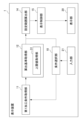
- FIG. 2 is a functional block diagram of the display device of the machine tool according to the first embodiment.
- 5 is a flowchart showing an example of a process flow of display control by the display device of the first embodiment.
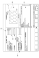
- 13 is a diagram showing an example of an image displayed on the display unit by the display device when the second processing condition is selected.
- FIG. 13 is a diagram showing an example of an image in which a setting range of a second processing condition is displayed on a display unit by a display device.
- FIG. FIG. 11 is a functional block diagram of a calculation criterion acquisition unit included in the display device of the second embodiment.
- FIG. 11 is a functional block diagram of a display device of a machine tool according to a third embodiment.
- FIG. 1 is a functional block diagram of a display device 1 of a machine tool according to a first embodiment.
- the display device 1 according to the first embodiment is a computer that displays on a display unit 20 various information of a machine tool that performs swing machining while swinging a cutting tool and a workpiece relative to one another.
- the display device 1 is used, for example, connected to a control device (not shown) that is a computer that controls the machine tool.
- the display device 1 assists in setting machining conditions for swing cutting.
- a machine tool processes a workpiece with a cutting tool by operating at least one spindle that rotates the cutting tool and the workpiece relative to one another, and at least one feed axis that moves the cutting tool relative to the workpiece.
- the machine tool performs various types of machining based on a machining program.
- the shape of the workpiece is not limited when machining with the machine tool according to this embodiment. In other words, it can be applied even when the workpiece has a tapered or arc-shaped portion on the machining surface, requiring multiple feed axes (Z-axis and X-axis), or when the workpiece is cylindrical or cylindrical and only one specific feed axis (Z-axis) is sufficient.
- the display device 1 is configured, for example, using a computer equipped with memories such as a ROM (read only memory) and a RAM (random access memory), a CPU (control processing unit), and a communication control unit, all connected to each other via a bus.
- the display device 1 also further comprises a display unit 20 that displays various information, and an input unit 21 into which an operator inputs various information.
- the display unit 20 is configured, for example, by a display that displays various information.
- the input unit 21 is, for example, an operating means such as a touch panel, keyboard, or button.
- the display device 1 of the machine tool may be configured as a CNC (Computer Numerical Controller) and may be connected to a higher-level computer (not shown) such as a CNC or a PLC (Programmable Logic Controller).
- a higher-level computer such as a CNC or a PLC (Programmable Logic Controller).
- machining conditions such as rotation speed may be input to the display device 1 of the machine tool from the higher-level computer. It may also be an external computer for simulating oscillating cutting that is not connected to the machine tool.
- the display device 1 has, as its functional units, a condition selection unit 10, a first processing condition acquisition unit 11, a calculation criterion acquisition unit 12, an upper limit value acquisition unit 31, a setting range calculation unit 14, and a display control unit 15. These functional units of the display device 1 are realized by the cooperation of the CPU, memory, and the control program stored in the memory.
- the condition selection unit 10 is a condition selection function that selects a first machining condition and a second machining condition from among the machining conditions.
- the first machining condition and the second machining condition may be, for example, specified by the operator on the display unit 20 of the display unit 1 via the input unit 21 or an external computer, or may be specified in advance in the machining program, setting parameters of the machine tool, or the like. In addition, one or more of the first machining condition and the second machining condition may be specified.
- the machining conditions include information necessary for machining, such as the spindle speed S (1/min), the feed amount per spindle revolution F (mm/rev), the workpiece diameter (mm), the command position of the feed axis, and the oscillation conditions.
- the feed amount per spindle revolution (mm/rev) can also be calculated from a combination of the spindle speed (1/min) and the feed rate of the cutting tool (mm/min).
- the oscillation conditions included in the machining conditions include at least a frequency parameter, which is information about the oscillation frequency of the cutting tool or workpiece, and an amplitude parameter, which is information about the oscillation amplitude of the cutting tool or workpiece, as information for uniquely identifying the vibration waveform.
- the frequency parameter may be the relative number of vibrations per rotation of the cutting tool and workpiece, or the number of vibrations per unit time. It may also be a periodic parameter of the forward and backward movement.
- the amplitude parameter may be information about the oscillation amplitude relative to the relative feed amount per rotation of the cutting tool and workpiece, or a distance parameter of the forward and backward movement.
- These periodic parameters of the forward and backward movement and distance parameters of the forward and backward movement may be determined from the forward speed, backward speed, forward distance, backward distance, spindle rotation speed, control period, etc.
- the frequency parameter and amplitude parameter may be determined from the spindle rotation speed, feed rate per minute, frequency magnification, which is the relative number of vibrations per rotation of the cutting tool and workpiece, and amplitude magnification, which is the oscillation amplitude relative to the relative feed amount per rotation of the cutting tool and workpiece.
- the oscillation frequency f (Hz) per rotation of the spindle and the oscillation frequency magnification I (times) are used as frequency parameters.
- the oscillation frequency magnification I (times) may be specified directly, or may be calculated from the oscillation frequency (Hz) and the rotation speed S (1/min) of the spindle after specifying the oscillation frequency (Hz).
- the oscillation amplitude A (mm) relative to the magnitude of the feed amount per revolution of the spindle and the oscillation amplitude magnification K (times) indicating the magnitude of the oscillation amplitude are used.
- the oscillation amplitude magnification K (times) may also be directly specified in the same way.
- the feed rate per minute can also be set as a processing condition.
- frequency parameters, and amplitude parameters instead of the feed rate, frequency parameters, and amplitude parameters, the forward amount, forward speed, retraction amount, retraction speed, control cycle, number of teeth, etc. can also be set as processing conditions.
- the first machining condition acquisition unit 11 is a first machining condition acquisition function that acquires the first machining condition from among multiple machining conditions for performing oscillation machining.
- the calculation criteria acquisition unit 12 is a calculation criteria acquisition function that acquires two or more calculation criteria for calculating the setting range of one or more second processing conditions that are set in advance among the processing conditions. For example, the conditions under which chip shredding is possible are acquired as the calculation criteria.
- the calculation criterion acquisition unit 12 of this embodiment has an upper limit acquisition unit 31.
- the upper limit acquisition unit 31 is an upper limit acquisition function that acquires the upper limit value of the oscillation status (parameter) used to determine one of the calculation criteria.
- the upper limit of the swing status is L A and the lower limit is L B.
- Examples of the swing status include a frequency upper limit (L A > S ⁇ I), an amplitude upper limit (L A > F ⁇ K > L B ), a swing maximum speed upper limit (L A > F ⁇ S+(F ⁇ K) ⁇ (2 ⁇ S ⁇ I)/2), a swing maximum acceleration upper limit (L A > (F ⁇ K) ⁇ (2 ⁇ S ⁇ I) 2 /2), a swing maximum jerk upper limit (L A > (F ⁇ K) ⁇ (2 ⁇ S ⁇ I) 3 /2), etc.
- a return speed upper limit, etc. can also be used. In this way, the upper and lower limits of the swing status can be set to various parameters related to the swing conditions.
- the setting range calculation unit 14 calculates the setting range of the second processing condition based on the first processing condition and the calculation criterion. The calculation method of the setting range calculation unit 14 will be described later.
- the display control unit 15 is a display control function that displays various information of the display device 1 and information on the operator's input results on the display unit 20.
- the display control unit 15 also executes display control that displays an image based on the setting range of the second processing conditions calculated by the setting range calculation unit 14 on the display unit 20.
- FIG. 2 is a flowchart showing an example of the process flow of display control by the display device 1 of the first embodiment.
- the order and contents of the processes shown in the flowchart are merely examples, and the order and contents of the processes can be changed as appropriate.
- condition selection unit 10 determines the first and second processing conditions from among the processing conditions based on the input information from the operator (step S11).
- FIG. 3 is a diagram showing an example of an image displayed on the display unit 20 by the display device 1 when the second machining conditions are selected.
- the image shown in FIG. 3 includes a program display 51 showing the contents of the machining program, a tool path check display 52 showing the machining path of the cutting tool, an acceleration information display 53 showing information on maximum acceleration, etc., and a machining condition display 54 showing the machining conditions.
- the machining condition display 54 column 56 indicating whether or not chip cutting is possible is also blank.
- the condition selection unit 10 interprets this as meaning that the oscillation amplitude magnification K has been specified as the second machining condition, and determines the oscillation amplitude magnification K as the second machining condition. Then, among the machining conditions, the spindle speed S, feed rate F, and oscillation frequency magnification I that were not selected as the second machining condition are determined as the first machining conditions. Note that if there are blank columns other than the one selected by the operator, a process may be added to notify the operator of this.
- the first machining condition acquisition unit 11 acquires the first machining conditions based on the input information from the operator or the information previously set on the display device 1 (step S12).
- the second machining condition is the oscillation amplitude magnification K.
- the feed rate may be the feed amount per spindle rotation, the feed amount per time, or the feed amount per oscillation. In this example, it is acquired as the feed amount per spindle rotation.
- the calculation criterion acquisition unit 12 acquires a calculation criterion for calculating the setting range of the second machining condition based on information previously set in the display device 1 (step S13).
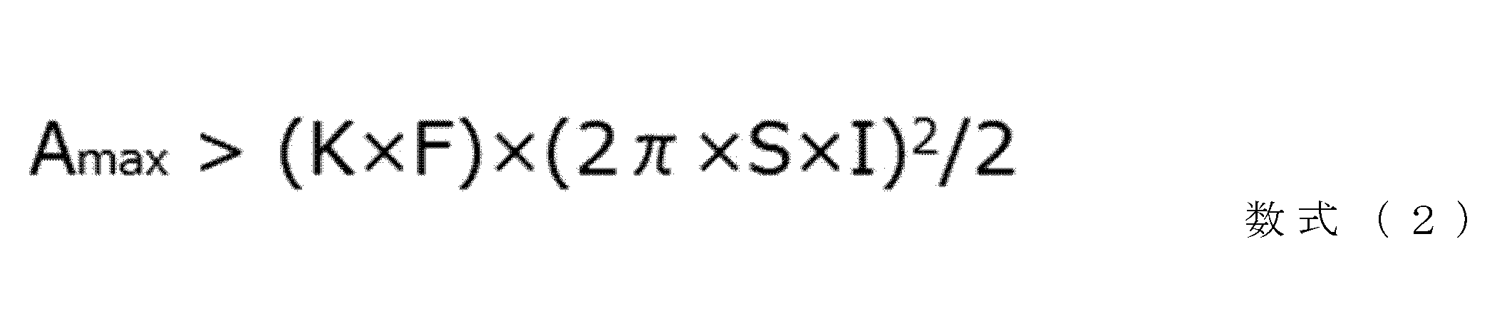
- two calculation criteria are acquired: that the oscillation motion is capable of shredding chips, and that the oscillation motion does not exceed the upper acceleration limit.
- the upper acceleration limit is acquired by the upper limit acquisition unit 31.
- the upper limit acquisition unit 31 acquires 9869.6 (mm/ s2 ) as the upper acceleration limit.
- the setting range calculation unit 14 calculates the setting range of the second machining conditions based on the first machining conditions acquired by the first machining condition acquisition unit 11 and the calculation criterion acquired by the calculation criterion acquisition unit 12 (step S14).
- the value of the oscillation amplitude magnification K is set to satisfy the following formula (1), which is the calculation criterion indicating that the oscillation operation will be capable of shredding chips, and the following formula (2), which is the calculation criterion indicating that the oscillation operation will not exceed the upper acceleration limit.
- the above formula (1) is written as the condition for an oscillating motion that allows chip shredding. This is the condition for the tool path paths of the nth rotation and the n+1th rotation to overlap and cause an air cut. However, in reality, even if an air cut does not occur, chip shredding may be possible if the cutting path distance is sufficiently short. Therefore, the condition for an oscillating motion that allows chip shredding may be determined by providing an additional margin to the above formula (1), or the machining conditions I and K and the table data of the actual machining results on whether or not chip shredding was actually possible at that time may be referenced to determine whether the conditions allow chip shredding.
- the display control unit 15 executes display control to display an image including the setting range of the oscillation amplitude magnification K as the second processing condition calculated by the setting range calculation unit 14 on the display unit 20 (step S15).
- FIG. 4 is a diagram showing an example of an image in which the setting range of the second processing condition is displayed on the display unit 20 by the display device 1.
- the setting range of the oscillation amplitude factor K set for the second processing condition 1.0 to 2.0
- the oscillation amplitude factor K is shown in the lower left column of the screen among the processing condition display 54.
- the operator can set the oscillation amplitude factor K to any value between 1.0 and 2.0, thereby making it possible to set conditions that allow chip shredding without exceeding the upper acceleration limit.
- the oscillation amplitude magnification K should be specifically within the range of 1.0 to 2.0, and this requires the operator to consider and decide on all aspects that are difficult to consider within the control device, such as the quality of the workpiece machining surface, the characteristics of the machine, the chip length, the maintainability of the machine, energy saving, etc.
- the setting range of K which is an essential condition, can be set to 1.0 to 2.0, adjustment will be much easier than before.
- the setting range was calculated from only two aspects, that is, the chips can be shredded and the upper acceleration limit is not exceeded, but the setting range can be further narrowed down by having the calculation criteria acquisition unit hold the calculation criteria considered by the operator as much as possible.
- it is very difficult for the control device to hold calculation criteria for all of the above aspects it is meaningful to calculate the range, and the rest can be left to the operator's judgment.
- the second machining condition is the oscillation frequency magnification I.
- K or I was specified as the second processing condition, but it is also possible to specify S and F as the first processing condition and both K and I as the second processing condition. In this case, it is sufficient to show the setting ranges of K and I two-dimensionally by a graph display, etc.
- the number of tool blades was calculated as 1, but if there are multiple tool blades, the number of tool blades may be obtained and the calculation may be performed taking the number of tool blades into account.
- the display device 1 for a machine tool that performs swing machining while swinging the cutting tool and the workpiece relative to one another provides the following effects:
- the display device 1 of the machine tool includes a first machining condition acquisition unit 11 that acquires at least one of the spindle speed, feed rate, frequency parameter, and amplitude parameter included in the machining conditions as the first machining condition, a calculation criterion acquisition unit 12 that acquires two or more calculation criteria for calculating the setting range of the second machining condition, which is a machining condition that was not acquired as the first machining condition among the machining conditions, based on the first machining condition, a setting range calculation unit 14 that calculates the setting range of the second machining condition based on the first machining condition and the calculation criterion, and a display control unit 15 that displays the setting range of the second machining condition on the display unit 20.
- a first machining condition acquisition unit 11 that acquires at least one of the spindle speed, feed rate, frequency parameter, and amplitude parameter included in the machining conditions as the first machining condition
- a calculation criterion acquisition unit 12 that acquires two or more calculation criteria for calculating the setting range of the second
- the calculation criteria acquisition unit 12 acquires at least a calculation criterion for calculating a setting range in which a machining operation based on the first machining conditions and the second machining conditions can shred chips. Machining conditions are unique and complex, and machining conditions that only satisfy the requirement of being able to shred chips can be found relatively easily. However, machining conditions that simultaneously satisfy other aspects become highly difficult. In this regard, with the configuration of this embodiment, it is possible to present to the operator a setting range for the second machining conditions that can shred chips and also satisfy other aspects.
- the display device 1 further includes an upper limit value acquisition unit 31 that acquires the upper limit value of the parameter set in the oscillation processing, and the calculation criterion acquisition units 12, 12A acquire at least a calculation criterion for calculating a setting range such that the oscillation parameter calculated from the second processing conditions becomes a value corresponding to the upper limit value.
- the display device 1 further includes a condition selection unit 10 that selects the first processing condition and the second processing condition from among the processing conditions. This allows the first processing condition and the second processing condition to be arbitrarily selected from among the processing conditions, or the initial settings to be changed, by input from the operator or by setting the display device 1, etc.
- the display device 1 further includes an input unit 21 that allows the operator to select one of the processing conditions, and the condition selection unit 10 selects the processing condition selected by the input unit 21 as the second processing condition, and selects a processing condition different from that selected by the input unit 21 as the first processing condition.
- a display device 1 according to a second embodiment which performs display control different from that of the display device 1 according to the first embodiment.
- the configuration of the display device 1 according to the second embodiment is similar to that of the first embodiment.
- the calculation criteria acquired by the calculation criteria acquisition unit 12A and the method of calculating the setting range of the second processing conditions based on the calculation criteria are different from those in the first embodiment.
- FIG. 5 is a functional block diagram of the calculation criterion acquisition unit 12A provided in the display device 1 of the second embodiment.
- the calculation criterion acquisition unit 12A of the second embodiment includes an upper limit value acquisition unit 31, a target chip length acquisition unit 32, a target surface roughness acquisition unit 33, a target variation acquisition unit 34, a cycle time target acquisition unit 35, and a cycle time analysis unit 36.
- the upper limit value acquisition unit 31 has the same configuration as in the first embodiment.
- the target values here can also be called the allowable values for operation.
- the target values may be theoretically calculated values, or may be output values of a learning model based on past performance or reference values of a database.
- the target values may be information that is preset in the display device 1, or may be based on information input by the operator.
- the target chip length acquisition unit 32 is a target chip length acquisition function that acquires a target chip length, which is a target value of the chip length, as a calculation standard.
- the set range calculation unit 14 calculates a set range that is a value according to the target chip length. In the second embodiment, the set range calculation unit 14 calculates a set range such that the chip length calculated from the first machining condition and the second machining condition falls below the target value of the chip length acquired by the target chip length acquisition unit 32.
- the set range is calculated such that parameters such as the oscillation frequency magnification I and the oscillation amplitude magnification K of the known function f(I, K) that calculates the chip length satisfy the following: chip length upper limit value L A > f(I, K) > chip length lower limit value L B.
- the known function f(I, K) may be, for example, a simple chip length calculation formula where the workpiece diameter is ⁇ [mm] and the chip length is ⁇ /I, or a more accurate calculation method may be one where the phase difference in the workpiece from one end of the tool path where air cutting occurs is calculated as a numerical calculation from I and K, and the chip length is calculated from the phase difference and ⁇ . This makes it possible to present to the operator the setting range of the second machining conditions that satisfy the desired chip length condition.
- the target surface roughness acquisition unit 33 is a target surface roughness acquisition function that acquires a target surface roughness, which is a target value of the surface roughness, as a calculation standard.
- the set range calculation unit 14 calculates a set range that is a value according to the target surface roughness. In the second embodiment, the set range calculation unit 14 calculates a set range such that the surface roughness calculated from the first machining condition and the second machining condition falls below the target value of the surface roughness acquired by the target surface roughness acquisition unit 33.
- the set range is calculated such that the parameters of the known function f(F, I, K) that calculates the target surface roughness, such as the feed rate F, the oscillation frequency magnification I, and the oscillation amplitude magnification K, satisfy the surface roughness upper limit value L A > f(F, I, K).
- the known function f(F, I, K) may be obtained, for example, by separately acquiring the nose R [mm], calculating the surface roughness during oscillating cutting by numerical calculation based on the cutting path and the nose R calculated based on F, I, and K, and calculating a setting range such that the surface roughness during oscillating cutting satisfies the surface roughness upper limit value L A. This makes it possible to present to the operator the setting range of the second machining conditions that satisfy the desired target surface roughness conditions.
- the target variation acquisition unit 34 is a target surface roughness acquisition function that acquires a target variation index, which is a target value of an index related to the variation of the difference in surface roughness for each workpiece phase, as a calculation criterion.
- the variation index is an index related to the variation of the air cut location, and is a numerical value that indicates the variation of the machined surface.
- the index relating to the variation in the difference in surface roughness for each workpiece phase can be determined in advance as the standard deviation of the variation in surface roughness for each workpiece phase, rather than the surface roughness itself.
- the relationship between the standard deviation and the frequency multiplication factor is stored in the display device 1 as a table or function.
- the setting range calculation unit 14 calculates a setting range that corresponds to the target variation index.
- the setting range calculation unit 14 calculates the setting range so that the variation index calculated from the first machining condition and the second machining condition falls below the target variation index of surface roughness acquired by the target variation acquisition unit 34.
- the setting range is calculated so that a parameter such as the oscillation frequency magnification I of the function f(I) corresponding to the above-mentioned table satisfies the target variation index (upper limit value) L A > f(I). This makes it possible to present to the operator the setting range of the second machining condition that satisfies the desired surface roughness variation condition.
- the cycle time target acquisition unit 35 acquires the target value of the cycle time of the machining operation.
- the cycle time analysis unit 36 is a cycle time analysis function that executes a process to calculate the cycle time.
- the set range calculation unit 14 calculates a set range that corresponds to the target value of the cycle time. In the second embodiment, the set range calculation unit 14 calculates a set range such that the cycle time calculated by the cycle time analysis unit 36 from the first machining condition and the second machining condition falls below the target value of the cycle time acquired by the cycle time target acquisition unit 35.
- the setting range is calculated so that the parameters of the spindle speed S, feed rate F, etc. of the known function f(S, F) for calculating the cycle time satisfy the cycle time allowable value (upper limit) L A > f(S, F).
- the known function f(S, F) outputs the cycle time at the set S and F by using, for example, S and F as variables and a machining simulation function in combination. It is sufficient to calculate the setting range of S and F such that this cycle time is equal to or less than L A.
- S or F, or both are specified as the second machining condition.
- the second machining condition may be specified as S or F instead of I or K.
- the setting range calculation unit 14 of the second embodiment calculates the setting range of the second processing conditions according to each of the target values described above.
- the setting range of the second processing conditions is calculated so as to satisfy all of the multiple target values (tolerance values).
- the example of the target value in the second embodiment is merely an example.
- some of the upper limit value acquisition unit 31, the target chip length acquisition unit 32, the target surface roughness acquisition unit 33, the target variation acquisition unit 34, the cycle time target acquisition unit 35, and the cycle time analysis unit 36 may be omitted, or a configuration for acquiring a target value set for another parameter may be added.
- target values can be set for various parameters that vary with S, F, I, and K as variables, such as feed rate tolerances, tool tolerances, frequency parameter tolerances, amplitude parameter tolerances, and air cut amount (chip shredding reliability) tolerances. If it is theoretically possible to calculate the ranges between these index values and S, F, I, and K, the calculations can be based on the theoretical calculation formula. If this is not possible, the setting ranges can be calculated using the output values of a learning model or database values based on past performance between these index values and S, F, I, and K, or by numerical calculation as described above.
- Fig. 6 is a functional block diagram of the display device 1A for a machine tool according to the third embodiment.
- the display device 1A includes, as functional units, a condition selection unit 10, a first processing condition acquisition unit 11, a calculation criterion acquisition unit 12, an upper limit value acquisition unit 31, a setting range calculation unit 14A, a display control unit 15, a second setting range acquisition unit 41, a priority item acquisition unit 42, and a recommended value calculation unit 43.
- the components of the display device 1A are the same as those in the first embodiment, except for the second setting range acquisition unit 41, the setting range calculation unit 14A, the priority acquisition unit 42, and the recommended value calculation unit 43.
- the second setting range acquisition unit 41 acquires the second setting range of the second machining condition.
- the second setting range is calculated by the operator's input, the display device 1, the control device of the machine tool, or the like, or is set in advance.
- the second setting range is set for each machining condition.
- the second setting range is, for example, a recommended upper limit value, a recommended lower limit value, or a recommended range.
- the second setting range acquisition unit 41 acquires the second setting range of 0.8 to 1.5 as the recommended range to be set for the oscillation amplitude magnification K of the second machining condition.
- the second setting range of 0.8 to 1.5 is output to the setting range calculation unit 14A.
- the setting range calculation unit 14A calculates the setting range of the second processing condition based on the first processing condition and the calculation criterion (formula (1) and formula (2)) in the same manner as in the first embodiment.
- the setting range calculation unit 14A calculates the setting range of the oscillation amplitude magnification K as the second processing condition, which is 1.0 to 2.0.
- the setting range calculation unit 14A compares the calculated setting range of the oscillation amplitude magnification K, 1.0 to 2.0, with the second setting range of 0.8 to 1.5 acquired by the second setting range acquisition unit 41.
- the setting range calculation unit 14A performs recalculation to correct the setting range of the oscillation amplitude magnification K, 1.0 to 1.5, based on the overlapping range of the setting range of the oscillation amplitude magnification K, 1.0 to 2.0, and the second setting range, 0.8 to 1.5.
- the setting range calculation unit 14A outputs the setting range of the oscillation amplitude magnification K, 1.0 to 1.5, as the setting range of the second processing condition after correction.
- the priority acquisition unit 42 acquires priorities that are input by an operator, calculated by the display device 1 or the control device of the machine tool, or set in advance.
- the priorities are calculation standards for calculating recommended values within the setting range of the second machining conditions.
- the realization of a machining operation that minimizes the acceleration ((K ⁇ F) ⁇ (2 ⁇ S ⁇ I) 2 /2) is set as the priority.
- the recommended value calculation unit 43 calculates a recommended value based on the priority items acquired by the priority item acquisition unit 42 and the setting range of the second processing condition output by the setting range calculation unit 14A.
- the recommended value is the value at which the above-mentioned acceleration ((K ⁇ F) ⁇ (2 ⁇ S ⁇ I) 2 /2) is smallest.
- the display control unit 15 outputs the recommended value to the display unit 20 as the setting range of the second processing condition.
- the display control unit 15 can also display the setting range from which the recommended value was calculated together with the recommended value.
- the display device 1A of the third embodiment described above further includes a second setting range acquisition unit 41 that acquires a second setting range of the second processing conditions that is different from the setting range of the second processing conditions calculated by the setting range calculation unit 14A, and the setting range calculation unit 14A calculates the setting range of the second processing conditions by reflecting the second setting range acquired by the second setting range acquisition unit 41. This makes it possible to present to the operator the setting range of the second processing conditions that reflects the range of the second processing conditions set from a different perspective.
- the display device 1A further includes a priority item acquisition unit 42 that acquires priorities for uniquely calculating a recommended value, and a recommended value calculation unit 43 that calculates a recommended value for the second processing condition based on the setting range of the second processing condition calculated by the priority item and setting range calculation unit 14A. This allows the operator to grasp the unique recommended value that satisfies the contents set in the priority items, making it easier to set processing conditions without the trouble of selecting a value from the setting range.
- the processing conditions are not limited to numerical values, and may be a predetermined numerical range.
- a fourth embodiment will be described in which at least one of the first processing conditions is set to a numerical range.
- the configuration of the display device 1 of the fourth embodiment is also the same as that of the first embodiment.
- the calculation criterion is that the oscillation operation does not exceed the upper frequency limit value, and that the surface roughness variation index is below a certain level.
- the calculation criterion acquisition unit 12 acquires two calculation criteria, as in the first embodiment: that the oscillation motion is capable of shredding chips, and that the oscillation motion does not exceed the upper acceleration limit.
- the first processing condition acquisition unit 11 acquires at least one of the first processing conditions as the setting range of the first processing condition
- the setting range calculation unit 14 calculates the setting range of the second processing condition based on at least the setting range of the first processing condition and the calculation criterion.
- the calculation criterion acquisition unit (12) acquires at least a calculation criterion for calculating a setting range of the second machining conditions in which a machining operation based on at least the second machining conditions can shred chips.
- the calculation criterion acquisition unit (12, 12A) acquires at least a calculation criterion for calculating a setting range of the second processing condition such that the oscillation parameter calculated based on at least the second processing condition becomes a value corresponding to the upper limit value.
- the calculation criterion acquisition unit (12A) acquires at least a calculation criterion for calculating a setting range of the second machining conditions such that a chip length calculated based on at least the second machining conditions becomes a value corresponding to the target chip length.
- the calculation criterion acquisition unit (12A) acquires at least a calculation criterion for calculating a setting range of the second machining conditions such that the surface roughness calculated based on at least the second machining conditions becomes a value corresponding to the target surface roughness.
- a target variation acquisition unit (34) is provided for acquiring a target value of a variation index relating to the variation of the machined surface of the difference in surface roughness for each work phase
- the calculation criterion acquisition unit (12A) acquires at least a calculation criterion for calculating a setting range of the second processing condition such that the variation index calculated from at least the second processing condition becomes a value corresponding to the target value.
- a cycle time target value acquisition unit (35) that acquires a target value of a cycle time
- a cycle time analysis unit (36) for performing cycle time analysis
- the calculation criterion acquisition unit (12A) acquires at least a calculation criterion for calculating a setting range of the second machining condition such that the cycle time calculated from at least the second machining condition and the cycle time analysis unit becomes a value corresponding to the target value.
- the apparatus further includes a second setting range acquisition unit (41) that acquires a second setting range of a second processing condition different from the setting range of the second processing condition calculated by the setting range calculation unit (14A),
- the set range calculation section (14A) calculates a set range of the second machining condition by reflecting the second set range acquired by the second set range acquisition section (41).
- a priority acquisition unit (42) for acquiring priorities for uniquely calculating a recommendation value In the above-mentioned display device (1A) of the machine tool, a priority acquisition unit (42) for acquiring priorities for uniquely calculating a recommendation value; The apparatus further includes a recommended value calculation unit (43) that calculates the recommended value of the second machining condition based on the priority item and the setting range of the second machining condition calculated by the setting range calculation unit (14A).
- the first machining condition acquisition unit (11) acquires at least one of the first machining conditions as a setting range of the first machining condition
- the set range calculation unit (14) calculates a set range of the second machining condition based on at least the set range of the first machining condition and the calculation criterion.
- the apparatus further includes a condition selection unit (10) for selecting the first processing condition and the second processing condition from among the processing conditions.
- the apparatus further includes an input unit (21) for allowing an operator to select one of the processing conditions,
- the condition selection unit (10) selects the machining conditions selected in the input unit (21) as second machining conditions, and selects machining conditions different from those selected in the input unit (21) as first machining conditions.
Landscapes
- Engineering & Computer Science (AREA)
- Physics & Mathematics (AREA)
- Human Computer Interaction (AREA)
- Manufacturing & Machinery (AREA)
- General Physics & Mathematics (AREA)
- Automation & Control Theory (AREA)
- Geometry (AREA)
- Mechanical Engineering (AREA)
- Numerical Control (AREA)
- Automatic Control Of Machine Tools (AREA)
Abstract
Description
図1は、第1実施形態に係る工作機械の表示装置1の機能ブロック図である。第1実施形態に係る表示装置1は、切削工具とワークを相対的に揺動させながら揺動加工を行う工作機械の各種情報を表示部20に表示するコンピュータである。表示装置1は、例えば、工作機械の制御を行うコンピュータである不図示の制御装置に接続されて使用される。表示装置1は、揺動切削の加工条件の設定を支援する。

次に、第1実施形態の表示装置1とは異なる表示制御を行う第2実施形態の表示装置1について説明する。第2実施形態の表示装置1の構成は、第1実施形態と同様の構成である。
次に、第3実施形態の表示装置1Aについて説明する。図6は、第3実施形態に係る工作機械の表示装置1Aの機能ブロック図である。
上記実施形態では、加工条件は、数値に限定される訳ではなく、所定の数値範囲であってもよい。次に、第1加工条件のうち、少なくとも1つが数値範囲に設定される第4実施形態について説明する。なお、第4実施形態の表示装置1の構成も、第1実施形態と同様の構成である。
(付記1)
切削工具とワークを相対的に揺動させながら揺動加工を行う工作機械の表示装置(1、1A)であって、
加工条件に含まれる主軸回転数、送り速度、周波数パラメータ及び振幅パラメータのうち少なくとも1つを第1加工条件として取得する第1加工条件取得部(11)と、
前記加工条件のうち前記第1加工条件として取得されなかった少なくとも1つの加工条件である第2加工条件の設定範囲を算出するための算出基準を2つ以上取得する算出基準取得部(12,12A)と、
前記第1加工条件と前記算出基準に基づいて前記第2加工条件の設定範囲を算出する設定範囲算出部(14、14A)と、
前記第2加工条件の設定範囲を表示部(20)に表示する表示制御部(15)と、を備える工作機械の表示装置(1、1A)。
上記の工作機械の表示装置(1、1A)において、
前記算出基準取得部(12)は、少なくとも前記第2加工条件に基づく加工動作が切屑細断可能となる前記第2加工条件の設定範囲を算出するための算出基準を少なくとも取得する。
上記の工作機械の表示装置(1、1A)において、
揺動加工で設定されるパラメータの上限値を取得する上限値取得部(31)を更に備え、
前記算出基準取得部(12、12A)は、少なくとも前記第2加工条件に基づき算出される揺動のパラメータが、前記上限値に応じた値になるような前記第2加工条件の設定範囲を算出する算出基準を少なくとも取得する。
上記の工作機械の表示装置(1)において、
目標の切屑長さを取得する目標切屑長さ取得部(32)を更に備え、
前記算出基準取得部(12A)は、少なくとも前記第2加工条件に基づき算出される切屑長さが、前記目標切屑長さに応じた値になるような前記第2加工条件の設定範囲を算出する算出基準を少なくとも取得する。
上記の工作機械の表示装置(1)において、
目標の面粗さを取得する目標面粗さ取得部(33)を更に備え、
前記算出基準取得部(12A)は、少なくとも前記第2加工条件に基づき算出される面粗さが、前記目標面粗さに応じた値になるような前記第2加工条件の設定範囲を算出する算出基準を少なくとも取得する。
上記の工作機械の表示装置(1)において、
ワーク位相ごとの面粗さの差の加工面のばらつきに関するばらつき指標の目標値を取得する目標ばらつき取得部(34)を更に備え、
前記算出基準取得部(12A)は、少なくとも前記第2加工条件から算出される前記ばらつき指標が、前記目標値に応じた値になるような前記第2加工条件の設定範囲を算出する算出基準を少なくとも取得する。
上記の工作機械の表示装置(1)において、
サイクルタイムの目標値を取得するサイクルタイム目標値取得部(35)と、
サイクルタイム解析をするサイクルタイム解析部(36)と、を更に備え、
前記算出基準取得部(12A)は、少なくとも前記第2加工条件と前記サイクルタイム解析部から算出されるサイクルタイムが、前記目標値に応じた値になるような前記第2加工条件の設定範囲を算出する算出基準を少なくとも取得する。
上記の工作機械の表示装置(1A)において、
前記設定範囲算出部(14A)が算出する前記第2加工条件の設定範囲とは異なる第2加工条件の第2設定範囲を取得する第2設定範囲取得部(41)を更に備え、
前記設定範囲算出部(14A)は、前記第2設定範囲取得部(41)が取得した前記第2設定範囲を反映して前記第2加工条件の設定範囲を算出する。
上記の工作機械の表示装置(1A)において、
推奨値を一意に算出するための優先事項を取得する優先事項取得部(42)と、
前記優先事項及び前記設定範囲算出部(14A)が算出した前記第2加工条件の設定範囲に基づいて前記第2加工条件の前記推奨値を算出する推奨値算出部(43)と、を更に備える。
上記の工作機械の表示装置(1、1A)において、
前記第1加工条件取得部(11)は、前記第1加工条件のうち少なくとも1つを第1加工条件の設定範囲として取得し、
前記設定範囲算出部(14)は、少なくとも前記第1加工条件の設定範囲と前記算出基準に基づいて前記第2加工条件の設定範囲を算出する。
上記の工作機械の表示装置(1、1A)において、
前記加工条件の中から前記第1加工条件及び前記第2加工条件を選択する条件選択部(10)を更に備える。
上記の工作機械の表示装置(1、1A)において、
オペレータが前記加工条件の中の何れかを選択する入力部(21)を更に備え、
前記条件選択部(10)は、前記入力部(21)で選択された加工条件を第2加工条件として選択し、前記入力部(21)で選択したものとは異なる加工条件を前記第1加工条件として選択する。
切削工具とワークを相対的に揺動させながら揺動加工を行う工作機械のコンピュータ(1、1A)に、
加工条件に含まれる主軸回転数、送り速度、周波数パラメータ及び振幅パラメータのうち少なくとも1つを第1加工条件として取得する第1加工条件取得機能と、
前記加工条件のうち前記第1加工条件として取得されなかった少なくとも1つの加工条件である第2加工条件の設定範囲を前記第1加工条件に基づいて算出するための算出基準を2つ以上取得する算出基準取得機能と、
前記第1加工条件と前記算出基準に基づいて前記第2加工条件の設定範囲を算出する設定範囲算出機能と、を実現するプログラム。
10 条件選択部
11 第1加工条件取得部
12、12A 算出基準取得部
14、14A 設定範囲算出部
15 表示制御部
20 表示部
21 入力部
31 上限値取得部
32 目標切屑長さ取得部
33 目標面粗さ取得部
34 目標ばらつき取得部
35 サイクルタイム目標取得部
36 サイクルタイム解析部
41 第2設定範囲取得部
42 優先事項取得部
43 推奨値算出部
Claims (13)
- 切削工具とワークを相対的に揺動させながら揺動加工を行う工作機械の表示装置であって、
加工条件に含まれる主軸回転数、送り速度、周波数パラメータ及び振幅パラメータのうち少なくとも1つを第1加工条件として取得する第1加工条件取得部と、
前記加工条件のうち前記第1加工条件として取得されなかった少なくとも1つの加工条件である第2加工条件の設定範囲を算出するための算出基準を2つ以上取得する算出基準取得部と、
前記第1加工条件と前記算出基準に基づいて前記第2加工条件の設定範囲を算出する設定範囲算出部と、
前記第2加工条件の設定範囲を表示部に表示する表示制御部と、を備える、工作機械の表示装置。 - 前記算出基準取得部は、少なくとも前記第2加工条件に基づく加工動作が切屑細断可能となる前記第2加工条件の設定範囲を算出するための算出基準を少なくとも取得する、請求項1に記載の工作機械の表示装置。
- 揺動加工で設定されるパラメータの上限値を取得する上限値取得部を更に備え、
前記算出基準取得部は、少なくとも前記第2加工条件に基づき算出される揺動のパラメータが、前記上限値に応じた値になるような前記第2加工条件の設定範囲を算出する算出基準を少なくとも取得する、請求項1又は2に記載の工作機械の表示装置。 - 目標の切屑長さを取得する目標切屑長さ取得部を更に備え、
前記算出基準取得部は、少なくとも前記第2加工条件に基づき算出される切屑長さが、前記目標切屑長さに応じた値になるような前記第2加工条件の設定範囲を算出する算出基準を少なくとも取得する、請求項1から3の何れかに記載の工作機械の表示装置。 - 目標の面粗さを取得する目標面粗さ取得部を更に備え、
前記算出基準取得部は、少なくとも前記第2加工条件に基づき算出される面粗さが、前記目標面粗さに応じた値になるような前記第2加工条件の設定範囲を算出する算出基準を少なくとも取得する、請求項1から4の何れかに記載の工作機械の表示装置。 - ワーク位相ごとの面粗さの差の加工面のばらつきに関するばらつき指標の目標値を取得する目標ばらつき取得部を更に備え、
前記算出基準取得部は、少なくとも前記第2加工条件から算出される前記ばらつき指標が、前記目標値に応じた値になるような前記第2加工条件の設定範囲を算出する算出基準を少なくとも取得する、請求項1から5の何れかに記載の工作機械の表示装置。 - サイクルタイムの目標値を取得するサイクルタイム目標値取得部と、
サイクルタイム解析をするサイクルタイム解析部と、を更に備え、
前記算出基準取得部は、少なくとも前記第2加工条件と前記サイクルタイム解析部から算出されるサイクルタイムが、前記目標値に応じた値になるような前記第2加工条件の設定範囲を算出する算出基準を少なくとも取得する、請求項1から6の何れかに記載の工作機械の表示装置。 - 前記設定範囲算出部が算出する前記第2加工条件の設定範囲とは異なる第2加工条件の第2設定範囲を取得する第2設定範囲取得部を更に備え、
前記設定範囲算出部は、前記第2設定範囲取得部が取得した前記第2設定範囲を反映して前記第2加工条件の設定範囲を算出する、請求項1から7の何れかに記載の工作機械の表示装置。 - 推奨値を一意に算出するための優先事項を取得する優先事項取得部と、
前記優先事項及び前記設定範囲算出部が算出した前記第2加工条件の設定範囲に基づいて前記第2加工条件の前記推奨値を算出する推奨値算出部と、を更に備える、請求項1から8の何れかに記載の工作機械の表示装置。 - 前記第1加工条件取得部は、前記第1加工条件のうち少なくとも1つを第1加工条件の設定範囲として取得し、
前記設定範囲算出部は、少なくとも前記第1加工条件の設定範囲と前記算出基準に基づいて前記第2加工条件の設定範囲を算出する、請求項1から9の何れかに記載の工作機械の表示装置。 - 前記加工条件の中から前記第1加工条件及び前記第2加工条件を選択する条件選択部を更に備える、請求項1から10の何れかに記載の工作機械の表示装置。
- オペレータが前記加工条件の中の何れかを選択する入力部を更に備え、
前記条件選択部は、前記入力部で選択された加工条件を第2加工条件として選択し、前記入力部で選択したものとは異なる加工条件を前記第1加工条件として選択する、請求項11に記載の工作機械の表示装置。 - 切削工具とワークを相対的に揺動させながら揺動加工を行う工作機械のコンピュータに、
加工条件に含まれる主軸回転数、送り速度、周波数パラメータ及び振幅パラメータのうち少なくとも1つを第1加工条件として取得する第1加工条件取得機能と、
前記加工条件のうち前記第1加工条件として取得されなかった少なくとも1つの加工条件である第2加工条件の設定範囲を算出するための算出基準を2つ以上取得する算出基準取得機能と、
前記第1加工条件と前記算出基準に基づいて前記第2加工条件の設定範囲を算出する設定範囲算出機能と、を実現するプログラム。
Priority Applications (4)
| Application Number | Priority Date | Filing Date | Title |
|---|---|---|---|
| PCT/JP2023/017817 WO2024232104A1 (ja) | 2023-05-11 | 2023-05-11 | 工作機械の表示装置及びプログラム |
| JP2025519303A JPWO2024232104A1 (ja) | 2023-05-11 | 2023-05-11 | |
| DE112023005876.8T DE112023005876T5 (de) | 2023-05-11 | 2023-05-11 | Anzeigevorrichtung und Programm für Werkzeugmaschine |
| CN202380097784.1A CN121039588A (zh) | 2023-05-11 | 2023-05-11 | 机床的显示装置以及程序 |
Applications Claiming Priority (1)
| Application Number | Priority Date | Filing Date | Title |
|---|---|---|---|
| PCT/JP2023/017817 WO2024232104A1 (ja) | 2023-05-11 | 2023-05-11 | 工作機械の表示装置及びプログラム |
Publications (1)
| Publication Number | Publication Date |
|---|---|
| WO2024232104A1 true WO2024232104A1 (ja) | 2024-11-14 |
Family
ID=93430036
Family Applications (1)
| Application Number | Title | Priority Date | Filing Date |
|---|---|---|---|
| PCT/JP2023/017817 Ceased WO2024232104A1 (ja) | 2023-05-11 | 2023-05-11 | 工作機械の表示装置及びプログラム |
Country Status (4)
| Country | Link |
|---|---|
| JP (1) | JPWO2024232104A1 (ja) |
| CN (1) | CN121039588A (ja) |
| DE (1) | DE112023005876T5 (ja) |
| WO (1) | WO2024232104A1 (ja) |
Citations (4)
| Publication number | Priority date | Publication date | Assignee | Title |
|---|---|---|---|---|
| JP6843313B1 (ja) * | 2020-06-03 | 2021-03-17 | 三菱電機株式会社 | 制御システム |
| WO2021167014A1 (ja) * | 2020-02-20 | 2021-08-26 | ファナック株式会社 | 工作機械の制御装置 |
| WO2022163634A1 (ja) * | 2021-01-28 | 2022-08-04 | ファナック株式会社 | 表示装置及びコンピュータプログラム |
| JP7252426B1 (ja) * | 2022-09-30 | 2023-04-04 | ファナック株式会社 | 工作機械の制御装置及び工作機械の表示装置 |
-
2023
- 2023-05-11 DE DE112023005876.8T patent/DE112023005876T5/de active Pending
- 2023-05-11 WO PCT/JP2023/017817 patent/WO2024232104A1/ja not_active Ceased
- 2023-05-11 JP JP2025519303A patent/JPWO2024232104A1/ja active Pending
- 2023-05-11 CN CN202380097784.1A patent/CN121039588A/zh active Pending
Patent Citations (4)
| Publication number | Priority date | Publication date | Assignee | Title |
|---|---|---|---|---|
| WO2021167014A1 (ja) * | 2020-02-20 | 2021-08-26 | ファナック株式会社 | 工作機械の制御装置 |
| JP6843313B1 (ja) * | 2020-06-03 | 2021-03-17 | 三菱電機株式会社 | 制御システム |
| WO2022163634A1 (ja) * | 2021-01-28 | 2022-08-04 | ファナック株式会社 | 表示装置及びコンピュータプログラム |
| JP7252426B1 (ja) * | 2022-09-30 | 2023-04-04 | ファナック株式会社 | 工作機械の制御装置及び工作機械の表示装置 |
Also Published As
| Publication number | Publication date |
|---|---|
| CN121039588A (zh) | 2025-11-28 |
| DE112023005876T5 (de) | 2025-12-24 |
| JPWO2024232104A1 (ja) | 2024-11-14 |
Similar Documents
| Publication | Publication Date | Title |
|---|---|---|
| JP6802213B2 (ja) | 工具選定装置及び機械学習装置 | |
| JP4847428B2 (ja) | 加工シミュレーション装置およびそのプログラム | |
| JP6261613B2 (ja) | 工作機械の制御装置 | |
| JP7252426B1 (ja) | 工作機械の制御装置及び工作機械の表示装置 | |
| JP2011043874A (ja) | 工作機械の工具ベクトル表示装置 | |
| WO2022181594A1 (ja) | 計算装置 | |
| JP4802170B2 (ja) | 加工時間算出装置およびそのプログラム | |
| JP4639058B2 (ja) | ねじ切り加工装置 | |
| JP2004206723A (ja) | 工具製造装置及び製造方法 | |
| KR100898034B1 (ko) | 공구경로 수정 방법 | |
| WO2024062544A1 (ja) | 工作機械の表示装置 | |
| JP2000235411A (ja) | 加工情報を用いた数値制御装置 | |
| KR101108211B1 (ko) | 복합선반용 파트프로그래밍 장치 및 복합 공정간 동기화 프로그램 생성방법 | |
| JP7525593B2 (ja) | 工作機械の制御装置、制御方法 | |
| WO2024232104A1 (ja) | 工作機械の表示装置及びプログラム | |
| JP2018180586A (ja) | シミュレーション装置、プログラム生成装置、制御装置およびコンピュータの表示方法 | |
| WO2024232099A1 (ja) | 計算装置 | |
| WO2024232103A1 (ja) | 工作機械の表示装置 | |
| WO2024232100A1 (ja) | 工作機械の表示装置、工作機械の制御装置及びプログラム | |
| JP7799048B2 (ja) | 工作機械の制御装置 | |
| CN117099061A (zh) | 信息处理装置及信息处理程序 | |
| JP7827878B2 (ja) | 工作機械の制御装置及び工作機械の表示装置 | |
| JP7794960B2 (ja) | 工作機械の制御装置 | |
| WO2025057300A1 (ja) | シミュレーション装置およびコンピュータ読み取り可能な記憶媒体 | |
| WO2024232102A1 (ja) | 工作機械の表示装置及び制御システム |
Legal Events
| Date | Code | Title | Description |
|---|---|---|---|
| 121 | Ep: the epo has been informed by wipo that ep was designated in this application |
Ref document number: 23936652 Country of ref document: EP Kind code of ref document: A1 |
|
| WWE | Wipo information: entry into national phase |
Ref document number: 112023005876 Country of ref document: DE |
|
| ENP | Entry into the national phase |
Ref document number: 2025519303 Country of ref document: JP Kind code of ref document: A |
|
| WWE | Wipo information: entry into national phase |
Ref document number: 2025519303 Country of ref document: JP |
|
| WWP | Wipo information: published in national office |
Ref document number: 112023005876 Country of ref document: DE |