WO2024232091A1 - パラメータ調整装置、及びコンピュータ読み取り可能な記録媒体 - Google Patents
パラメータ調整装置、及びコンピュータ読み取り可能な記録媒体 Download PDFInfo
- Publication number
- WO2024232091A1 WO2024232091A1 PCT/JP2023/017774 JP2023017774W WO2024232091A1 WO 2024232091 A1 WO2024232091 A1 WO 2024232091A1 JP 2023017774 W JP2023017774 W JP 2023017774W WO 2024232091 A1 WO2024232091 A1 WO 2024232091A1
- Authority
- WO
- WIPO (PCT)
- Prior art keywords
- parameter
- error
- calculation unit
- acquisition unit
- industrial machine
- Prior art date
- Legal status (The legal status is an assumption and is not a legal conclusion. Google has not performed a legal analysis and makes no representation as to the accuracy of the status listed.)
- Ceased
Links
Images




Classifications
-
- G—PHYSICS
- G05—CONTROLLING; REGULATING
- G05B—CONTROL OR REGULATING SYSTEMS IN GENERAL; FUNCTIONAL ELEMENTS OF SUCH SYSTEMS; MONITORING OR TESTING ARRANGEMENTS FOR SUCH SYSTEMS OR ELEMENTS
- G05B19/00—Program-control systems
- G05B19/02—Program-control systems electric
- G05B19/18—Numerical control [NC], i.e. automatically operating machines, in particular machine tools, e.g. in a manufacturing environment, so as to execute positioning, movement or co-ordinated operations by means of program data in numerical form
- G05B19/404—Numerical control [NC], i.e. automatically operating machines, in particular machine tools, e.g. in a manufacturing environment, so as to execute positioning, movement or co-ordinated operations by means of program data in numerical form characterised by control arrangements for compensation, e.g. for backlash, overshoot, tool offset, tool wear, temperature, machine construction errors, load, inertia
-
- G—PHYSICS
- G05—CONTROLLING; REGULATING
- G05B—CONTROL OR REGULATING SYSTEMS IN GENERAL; FUNCTIONAL ELEMENTS OF SUCH SYSTEMS; MONITORING OR TESTING ARRANGEMENTS FOR SUCH SYSTEMS OR ELEMENTS
- G05B2219/00—Program-control systems
- G05B2219/30—Nc systems
- G05B2219/50—Machine tool, machine tool null till machine tool work handling
- G05B2219/50289—Tool offset general
Definitions
- the present disclosure relates to a parameter adjustment device and a computer-readable recording medium.
- Machine tools are controlled based on a machining program to machine workpieces and manufacture products such as parts and molds.
- the target machining accuracy and machined surface quality are set in advance.
- the target machining time is also determined in advance.
- the machine tool operator checks the machining accuracy and machined surface quality of the machined product, while adjusting parameters such as acceleration/deceleration time constants and the movement speed commanded in the machining program.
- Machines that are configured with multiple axes in a complex relationship are required to evaluate and adjust the movement of the tip of the tool that processes the workpiece, rather than the movement of each axis.
- machines that use a parent-child turtle system in which a certain axis and other axes are moved in the same direction, machines with axes that are inclined at a certain angle to other axes, and machines with linear and rotary axes.
- the linear axis is evaluated using different indices, such as a length index (e.g., mm) and the rotary axis is evaluated using an angle index (e.g., deg), it is difficult to evaluate and adjust the movement of the tool tip.
- indices such as a length index (e.g., mm)
- angle index e.g., deg
- the parameter adjustment device for industrial machinery disclosed herein solves the above problem by performing kinematic transformation and making it possible to adjust parameters using errors at the tool tip.
- An aspect of the present disclosure is a parameter adjustment device that includes a state acquisition unit that acquires, as state data, a control amount related to a drive axis when an evaluation program is run in an industrial machine; a tool tip error calculation unit that kinematically converts the state data and calculates an error in at least one of the machining accuracy and the machined surface quality; a target acquisition unit that acquires a target value of the error in at least one of the machining accuracy and the machined surface quality; a parameter calculation unit that compares the error calculated by the tool tip error calculation unit with the target value of the error acquired by the target acquisition unit and calculates the value of the parameter based on the comparison result; and a parameter adjustment unit that adjusts the parameter value calculated by the parameter calculation unit to the industrial machine.
- FIG. 2 is a schematic hardware configuration diagram of the parameter adjustment device according to the first embodiment.
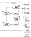
- FIG. 2 is a block diagram showing schematic functions of a parameter adjustment device according to the first embodiment.
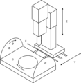
- FIG. 1 is a schematic diagram of a five-axis machining center equipped with three linear axes and two rotary axes.
- 10 is a table illustrating an example of status data of a five-axis machining center acquired by a status acquisition unit.
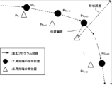
- FIG. 10 is a schematic diagram showing an example in which a commanded position of the tool tip and an actual position of the tool tip are plotted in space;
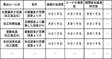
- FIG. 11 is a table illustrating an example of a rule for calculating parameters by a parameter calculation unit. 1 shows an example of a guideline for parameter adjustment.
- FIG. 13 is a block diagram showing schematic functions of a parameter adjustment device according to a modified example.
- FIG. 1 is a schematic hardware configuration diagram showing a main part of a parameter adjustment device according to an embodiment of the present disclosure.
- the parameter adjustment device 1 according to this embodiment can be implemented as a control device that controls industrial machinery such as a machine tool that moves a drive unit along a linear axis and a rotation axis by driving a motor.
- the parameter adjustment device 1 according to this embodiment can be implemented on a computer such as a personal computer attached to a control device that controls an industrial machine, a personal computer connected to the control device via a wired/wireless network, a cell computer, a fog computer 6, or a cloud server 7.
- a personal computer connected to a control device that controls an industrial machine 3 via a network 5.
- the CPU 11 provided in the parameter adjustment device 1 is a processor that controls the entire parameter adjustment device 1.
- the CPU 11 reads the system program stored in the ROM 12 via the bus 22, and controls the entire parameter adjustment device 1 in accordance with the system program.
- the RAM 13 temporarily stores temporary calculation data, display data, and various data input from outside.
- the non-volatile memory 14 is composed of, for example, a memory backed up by a battery (not shown) or an SSD (Solid State Drive), and retains its memory state even when the parameter adjustment device 1 is powered off.
- the non-volatile memory 14 stores control programs and data read from the external device 72 via the interface 15, data and control programs input via the input device 71, and various data acquired from the industrial machine 3.
- the control programs and data stored in the non-volatile memory 14 may be expanded in the RAM 13 when executed/used.
- various system programs such as well-known analysis programs are written in advance in the ROM 12.
- the industrial machine 3 is, for example, a machine tool such as a machining center or lathe that has at least one linear axis and at least one rotary axis.
- Sensors 4 are attached to the industrial machine 3 to detect physical quantities such as current, voltage, and vibration of each part when the industrial machine 3 is operating.
- the industrial machine 3 transmits data such as the command position according to the control program during machining, the position, speed, acceleration, jerk, vibration, and machining time of each axis via the network 5.
- the interface 15 is an interface for connecting the CPU 11 of the parameter adjustment device 1 to an external device 72 such as a USB memory, Compact Flash (registered trademark), or an SD card.
- an external device 72 such as a USB memory, Compact Flash (registered trademark), or an SD card.
- pre-stored control programs and various data can be read from the external device 72.
- control programs and various data edited within the parameter adjustment device 1 can be stored in the external device 72.
- the display device 70 displays the various data loaded into the memory, data obtained as a result of executing programs, etc., output via the interface 17.
- the input device 71 which is comprised of a keyboard, pointing device, etc., passes instructions and data based on operations by the operator to the CPU 11 via the interface 18.
- the interface 20 is an interface for connecting the CPU 11 of the parameter adjustment device 1 to a wired or wireless network 5.
- the network 5 may communicate using technologies such as serial communication such as RS-485, Ethernet (registered trademark), optical communication, wireless LAN, Wi-Fi (registered trademark), Bluetooth (registered trademark), etc.
- the industrial machines 3, fog computers 6, cloud servers 7, etc. are connected to the network 5, and data is exchanged between the parameter adjustment device 1 and the network 5.
- FIG. 2 is a schematic block diagram showing the functions of the parameter adjustment device 1 according to the first embodiment of the present disclosure.
- Each function of the parameter adjustment device 1 according to this embodiment is realized by the CPU 11 of the parameter adjustment device 1 shown in FIG. 1 executing a system program and controlling the operation of each part of the parameter adjustment device 1.
- the parameter adjustment device 1 of this embodiment includes a state acquisition unit 100, a tool tip error calculation unit 110, a target acquisition unit 120, a parameter calculation unit 130, and a parameter adjustment unit 140.
- a target error storage unit 200 which is an area in which errors related to the target position and errors related to the speed are stored, is prepared in advance on the RAM 13 to the non-volatile memory 14 of the parameter adjustment device 1.
- the state acquisition unit 100 acquires control amounts related to the drive shafts of the industrial machine 3 as state data.
- the control amounts related to the drive shafts of the industrial machine 3 may include, for example, data indicating command positions of each drive shaft commanded by a control program. They may also include data indicating actual positions of each drive shaft provided in the industrial machine 3.
- the state acquisition unit 100 acquires parameters related to the control of the movement amount including an N-th order time differential element (N is a natural number) during control of the industrial machine 3. These parameters are, for example, linear acceleration [mm/sec 2 ], linear jerk [mm/sec 3 ], corner speed difference [mm/min], post-interpolation acceleration/deceleration time constant [msec], position loop gain, feedforward coefficient, etc.
- a predetermined evaluation control program (hereinafter referred to as the evaluation program) created in advance in the industrial machine 3 is operated to acquire the command position of each drive axis according to each command issued by the evaluation program and the transition of the actual position of each drive axis during operation according to each command.
- the transition of the actual position of each drive axis may be acquired, for example, at every predetermined sampling period.
- the status acquisition unit 100 may acquire the time taken from the start to the end of control based on the evaluation program.
- the status acquisition unit 100 outputs the acquired status data to the tool tip error calculation unit 110.
- the tool tip error calculation unit 110 kinematically transforms the input state data and calculates the maximum error of the actual position relative to the commanded tool tip position.
- the kinematic transformation is a transformation from the position of each drive axis to the position of the tool tip using a formula that indicates the relationship between the position of each drive axis and the tool tip position, which is derived based on the configuration of the industrial machine 3.
- the tool tip error calculation unit 110 performs kinematic transformation based on the commanded position of each drive axis and calculates the commanded tool tip position.
- the tool tip error calculation unit 110 also performs kinematic transformation based on the actual position of each drive axis and calculates the actual position of the tool tip. The difference between the commanded tool tip position and the actual tool tip position obtained by the kinematic transformation is then calculated as the error related to the tool tip position.
- the tool tip error calculation unit 110 may calculate the difference between the command speed by each command and the actual speed calculated based on the change in the actual position of the tool tip obtained by kinematic conversion as the error related to the speed of the tool tip. Similarly, the tool tip error calculation unit 110 may calculate an error related to the acceleration of the tool tip and an error related to the jerk. The tool tip error calculation unit 110 outputs the maximum value of each calculated error to the parameter calculation unit 130.
- FIGS. Fig. 3 is a schematic diagram of a five-axis machining center equipped with three linear axes (X-axis, Y-axis, Z-axis) and two rotary axes (B-axis, C-axis).
- a tool is moved by driving the three linear axes, the X-axis, Y-axis, and Z-axis.
- the two rotary axes, the B-axis and C-axis rotate a table.
- the position of each drive axis is commanded.
- FIG. 4 is a table showing an example of the status data of the five-axis machining center acquired by the status acquisition unit 100.
- the status data includes a command position commanded to each drive axis and an actual position of each drive axis.
- Times t i , t (i+1) , t (i+2) , ... are times for each predetermined sampling period.
- the positions of each drive axis are commanded by the evaluation program at the timing of time t i to the positions of xc i , yc i , zc i , bc i , and cc i to each axis, and at the timing of time t ( i+1), the positions of xc (i+1) , yc (i+1 ) , zc (i+1), bc (i+1) , and cc (i+1) to each axis.
- the actual position of each drive axis is acquired as feedback data of the motor that drives each drive axis at each predetermined sampling period.
- the tool tip error calculation unit 110 calculates the commanded tool tip position and the actual tool tip position by performing a kinematic transformation on the commanded position of each drive axis and the actual position of each drive axis contained in the status data acquired in this manner.
- the specific calculation of the kinematic transformation is already publicly known, for example, in JP 2019-057262 A, and therefore a detailed description will be omitted in this specification.
- Fig. 5 is a schematic diagram showing an example of a machining program path, a commanded position of the tool tip, and an actual position of the tool tip drawn in space.
- a solid arrow indicates a machining program path.
- a black circle indicates a commanded position of the tool tip.
- a white triangle indicates an actual position of the tool tip.
- Pc i (xkc i , ykc i , zkc i ) is a commanded position of the tool tip obtained by kinematic transformation based on the positions xc i , yc i , zc i , bc i , and cc i commanded for each drive axis at time t i .
- Pc (i+1) (xkc (i+1) , ykc (i+1) , zkc(i +1) ) is the commanded tool tip position obtained by kinematic transformation based on the positions xc(i+ 1 ) , yc (i+1) , zc (i+1) , bc (i+1 ), and cc (i+1) commanded for each drive axis at time t(i+1).
- Pr i ( xkri , ykri , zkri ) is the commanded actual tool tip position obtained by kinematic transformation based on the actual positions xri , yr i , zri , br i , and cr i of each drive axis at time t i .
- the position deviation can be calculated as the distance from the actual position Pr (i+1) of the tool tip to the command position Pc (i+1) .
- the shape error can be calculated as the distance from the actual position Pr (i+1) of the tool tip to the machining program path.
- the vibration error can be calculated based on the amplitude value of the frequency component contained in the difference between the actual position path and the command path.
- the tool tip error calculation unit 110 calculates the errors related to each actual position and outputs the maximum value to the parameter calculation unit 130 as the maximum actual position error.
- the distance between each actual position may be divided by the time difference to calculate the actual speed, and the difference between the calculated actual speed and the command speed may be calculated as the speed error at each actual position.
- the difference in actual speed may be calculated as the actual acceleration at each actual position, and the difference between the calculated actual acceleration and the maximum acceleration may be calculated as the acceleration error at each actual position. The same applies to the jerk error.
- the calculated value is then output to the parameter calculation unit 130.
- the target acquisition unit 120 acquires a target value for at least one of the errors of the machining accuracy and the machining surface quality.
- the target error may be, for example, a target shape error as a target error of the machining accuracy, a target position deviation as a target error of the machining surface quality, or a target vibration error.
- the target acquisition unit 120 may read and acquire a target error related to the position or a target error related to the speed that is stored in advance in the target error storage unit 200, for example.
- the target acquisition unit 120 may also display a screen (not shown) for setting a target error on the display device 70 and acquire a target error related to the position or a target error related to the speed based on an input from an operator.
- the target error related to the position or the target error related to the speed may be acquired from another computer such as the fog computer 6 or the cloud server 7.
- the parameter calculation unit 130 compares the error calculated by the tool tip error calculation unit 110 with the target error acquired by the target acquisition unit 120. Then, based on the comparison result, it calculates the value of a parameter related to the control of the industrial machine 3. The purpose of this calculation of the parameter value is to adjust the parameter value so that the time required for the operation of the industrial machine 3 based on the evaluation program is the shortest within a range in which the error calculated by the tool tip error calculation unit 110 falls within the target value of the error acquired by the target acquisition unit 120.
- the parameters calculated by the parameter calculation unit 130 are parameters related to the control of the movement amount per control period including an N- th order time differential element (N is a natural number), such as linear acceleration [mm/sec 2 ], linear jerk [mm/sec 3 ], corner speed difference [mm/min], post-interpolation acceleration/deceleration time constant [msec], position loop gain, feedforward coefficient, etc.
- N is a natural number
- the parameter calculation unit 130 may calculate the parameters by adjusting the values of each parameter acquired by the state acquisition unit 100 from the industrial machine 3 according to a predetermined calculation rule.
- This calculation rule sets how each parameter is changed when, for example, a comparison result between the error calculated by the tool tip error calculation unit 110 and the target error acquired by the target acquisition unit 120 meets a predetermined condition.
- FIG. 6 is a table showing an example of a parameter calculation rule by the parameter calculation unit 130.
- a rule for reducing position deviation, a rule for shortening machining time, a rule for reducing vibration, a rule for reducing shape error, and the like are defined.
- Conditions for applying each calculation rule are set for that calculation rule. For example, when the result of comparing the error calculated by the tool tip error calculation unit 110 with the target error acquired by the target acquisition unit 120 shows that the position error is greater than the target error, the rule for reducing position deviation is adopted.
- the parameter calculation unit 130 makes the value of the linear acceleration parameter smaller than the current value. Also, the value of the corner speed difference parameter is made smaller than the current value.
- the value of the post-interpolation acceleration/deceleration parameter is made larger than the current value.
- the extent to which the value of each parameter is to be increased/decreased may be determined by a predetermined value in advance, or may be changed according to the result of comparing the error calculated by the tool tip error calculation unit 110 with the target error acquired by the target acquisition unit 120.
- the amount of change in the parameter value may be increased according to the amount by which the calculated error exceeds the target error.
- the amount of change in the parameter value for each axis may be weighted according to the amount of movement of each axis.
- the parameter calculation unit 130 may calculate the parameters manually through the operation of an operator.
- the parameter calculation unit 130 displays to the operator the comparison result between the error calculated by the tool tip error calculation unit 110 and the target error acquired by the target acquisition unit 120, and also presents the current values of each parameter and an interface for changing those values.
- the parameter calculation unit 130 may display guidelines for parameter adjustment based on the comparison result between the current error and the target error.
- Figure 7 shows an example of a guideline for parameter adjustment.
- the parameter calculation unit 130 ends the calculation of the parameter values related to the control of the industrial machine 3 when a predetermined condition is satisfied.
- the predetermined condition may be set for each type of error.
- a predetermined threshold may be set in advance for each type of error, and the calculation of the parameter values related to the control of the industrial machine 3 may end when all differences between the calculated errors and the target errors are equal to or less than the predetermined threshold.
- an upper limit may be set for the number of times the parameter calculation unit 130 calculates the parameter and the number of times the parameter adjustment unit 140 adjusts the parameter.
- the parameter calculation unit 130 may count the number of times the parameter is calculated and adjusted, and may end the calculation of the parameter values related to the control of the industrial machine 3 when the number of times reaches the upper limit.
- the upper limit of the number of adjustments may be acquired by the target acquisition unit 120, for example.
- the parameter adjustment unit 140 sets the calculated parameter value in the industrial machine 3. Then, it instructs the industrial machine 3 to perform control based on the evaluation program. Then, it instructs the status acquisition unit 100 to acquire the control amount related to the drive shaft of the industrial machine 3 as status data.
- the parameter adjustment device 1 with the above configuration can evaluate the movement of the tool tip and adjust the parameters for industrial machinery 3 that is configured with multiple axes that are intricately related. Since it evaluates the movement of the tool tip point rather than evaluating each drive axis, it is possible to intuitively and easily adjust parameter values even for industrial machinery 3 that includes tilt axes, rotation axes, etc.
- the parameter adjustment device 1 may be used to adjust the parameters of the operation of a simulation device that imitates the operation of an industrial machine 3.
- the parameter adjustment device 1 and the simulation device 8 are connected via a network 5, as shown in FIG. 8.
- the state acquisition unit 100 acquires the control amount related to the drive shaft of the virtual industrial machine 3 as state data from the simulation device 8 that executes a simulation process based on the evaluation program.
- the parameter adjustment unit 140 sets the calculated parameter value in the simulation device 8.
- the parameter calculation unit 130 may, in addition to the method using the calculation rules described above, perform a full search for the values of each parameter, or may use publicly known techniques such as reinforcement learning or optimization methods. These parameter calculation methods are particularly useful when adjusting parameters for a simulation device. When performing a full search for parameter values or using optimization methods such as reinforcement learning, it is necessary to repeatedly execute an evaluation program to adjust the parameters. When using a simulation device, the physical mechanical configuration will not break down even if it is operated repeatedly, so it is possible to efficiently adjust the parameters to appropriate values.
- the target acquisition unit 120 may further acquire an adjustment range for the value of each parameter.
- the parameter calculation unit 130 then calculates the value of each parameter within the adjustment range for the value of each parameter acquired by the target acquisition unit 120. In this way, it is possible to prevent the parameter calculation unit 130 from calculating the value of a parameter that cannot be set.
- the state acquisition unit 100 may acquire at least one of the information related to the mechanical configuration of the industrial machine 3, the predetermined offset amount of the tool or workpiece, and the coordinate conversion between predetermined coordinate systems.
- the information acquired in this manner is used by the tool tip error calculation unit 110 to perform kinematic conversion.
- the mechanical configuration includes the relationship between the respective axes.
- the tool offset amount and the workpiece offset amount can be used to correct the position of the tool tip.
- the coordinates of each drive axis are converted using information related to the coordinate conversion between the coordinate systems before the kinematic conversion is performed. In this manner, it becomes possible to accommodate various configurations of the industrial machine 3.
- a parameter adjustment device (1) includes a state acquisition unit (100) that acquires, as state data, a control amount related to a drive axis when an evaluation program is operated in an industrial machine (3), a tool tip error calculation unit (110) that kinematically converts the state data and calculates an error of at least one of machining accuracy and machined surface quality, a target acquisition unit (120) that acquires a target value of the error of at least one of machining accuracy and machined surface quality, a parameter calculation unit (130) that compares the error calculated by the tool tip error calculation unit (110) with the target value of the error acquired by the target acquisition unit (120) and calculates a value of a parameter related to the operation of the industrial machine (3) based on the comparison result, and a parameter adjustment unit (140) that adjusts the parameter value calculated by the parameter calculation unit (130) to the industrial machine (3).
- a state acquisition unit (100) that acquires, as state data, a control amount related to a drive axis when an evaluation program is operated in an industrial machine (3)
- the state acquisition unit (100) acquires at least one of information relating to a mechanical configuration of the industrial machine (3), a predetermined offset amount, and coordinate transformation
- the tool tip error calculation unit (110) kinematically transforms the state data based on at least one of information relating to a mechanical configuration of the industrial machine (3), a predetermined offset amount, and coordinate transformation, to calculate an error.
- the target acquisition unit (120) acquires an adjustment range for the value of the parameter
- the parameter calculation unit (130) calculates the parameter within the adjustment range.
- the target acquisition unit (120) acquires an upper limit number of times for adjusting the value of the parameter, and when the upper limit number of times for calculating the value of the parameter is reached, the parameter calculation unit (130) terminates the parameter calculation and the parameter adjustment by the parameter adjustment unit (140).
- the state acquisition unit (100) acquires the time taken to operate the evaluation program
- the parameter calculation unit (130) calculates parameter values so that the time taken for the operation of the industrial machine (3) based on the evaluation program is shortest within a range in which the error calculated by the tool tip error calculation unit (110) falls within the target value of the error acquired by the target acquisition unit (120).
- a computer-readable recording medium records a program that causes a computer to operate as a status acquisition unit (100) that acquires, as status data, a control amount related to a drive axis when an evaluation program is run in an industrial machine (3), a tool tip error calculation unit (110) that kinematically converts the status data and calculates an error in at least one of machining accuracy and machined surface quality, a target acquisition unit (120) that acquires a target value of an error in at least one of machining accuracy and machined surface quality, a parameter calculation unit (130) that compares the error calculated by the tool tip error calculation unit (110) with the target value of the error acquired by the target acquisition unit (120) and calculates a parameter value related to the operation of the industrial machine (3) based on the comparison result, and a parameter adjustment unit (140) that adjusts the parameter value calculated by the parameter calculation unit (130) to the industrial machine (3).
Landscapes
- Engineering & Computer Science (AREA)
- Human Computer Interaction (AREA)
- Manufacturing & Machinery (AREA)
- Physics & Mathematics (AREA)
- General Physics & Mathematics (AREA)
- Automation & Control Theory (AREA)
- Numerical Control (AREA)
Abstract
Description
生産現場では、工具先端における動きを評価し易い調整方法が望まれている。
[第1実施形態]
図1は本開示の一実施形態によるパラメータ調整装置の要部を示す概略的なハードウェア構成図である。本実施形態によるパラメータ調整装置1は、モータが駆動することで直線軸及び回転軸に沿って駆動部を移動させる工作機械などの産業機械を制御する制御装置として実装することができる。また、本実施形態によるパラメータ調整装置1は、産業機械を制御する制御装置に併設されたパソコンや、有線/無線のネットワークを介して制御装置と接続されたパソコン、セルコンピュータ、フォグコンピュータ6、クラウドサーバ7などのコンピュータ上に実装することができる。以下では、産業機械3を制御する制御装置とネットワーク5を介して接続されたパソコンの上にパラメータ調整装置1を実装した例を示す。
図3は、直線3軸(X軸、Y軸、Z軸)と回転2軸(B軸、C軸)を備えた5軸加工機の概略的な構成図である。図3の例示する5軸加工機では、X軸、Y軸、Z軸の直線3軸を駆動させることで工具を移動させている。一方、B軸及びC軸の回転2軸がテーブルを回転させている。評価用プログラムでは、例えば各駆動軸の位置が指令される。
(付記1)
本開示の一態様によるパラメータ調整装置(1)は、産業機械(3)において評価用プログラムを動作させた際の駆動軸に係る制御量を状態データとして取得する状態取得部(100)と、前記状態データをキネマティクス変換し、加工精度及び加工面品位の少なくともいずれかの誤差を算出する工具先端誤差算出部(110)と、加工精度及び加工面品位の少なくともいずれかの誤差の目標値を取得する目標取得部(120)と、前記工具先端誤差算出部(110)で算出した誤差と、前記目標取得部(120)で取得した誤差の目標値を比較し、その比較結果に基づいて前記産業機械(3)の動作に係るパラメータの値を算出するパラメータ算出部(130)と、前記パラメータ算出部(130)で算出したパラメータの値を前記産業機械(3)へ調整するパラメータ調整部(140)と、を備える。
本開示の他の態様によるパラメータ調整装置(1)は、前記状態取得部(100)は、前記産業機械(3)の機械構成、所定のオフセット量及び座標変換に係る情報の少なくともいずれかを取得し、前記工具先端誤差算出部(110)は、前記産業機械(3)の機械構成、所定のオフセット量及び座標変換に係る情報の少なくともいずれかに基づいて前記状態データをキネマティクス変換して誤差を算出する。
(付記3)
本開示の他の態様によるパラメータ調整装置(1)は、前記目標取得部(120)は、前記パラメータの値の調整範囲を取得し、前記パラメータ算出部(130)は、前記調整範囲の中でパラメータを算出する。
本開示の他の態様によるパラメータ調整装置(1)は、前記目標取得部(120)は、前記パラメータの値の調整の上限回数を取得し、前記パラメータ算出部(130)は、前記パラメータの値の算出を前記上限回数に到達すると、前記パラメータ算出部(130)によるパラメータの算出及び前記パラメータ調整部(140)によるパラメータの調整を終了する。
(付記5)
本開示の他の態様によるパラメータ調整装置(1)は、前記状態取得部(100)は、前記評価用プログラムを動作させた際に掛かった時間を取得し、前記パラメータ算出部(130)は、前記工具先端誤差算出部(110)が算出した誤差が、前記目標取得部(120)が取得した誤差の目標値の内に収まる範囲で、前記評価用プログラムに基づく前記産業機械(3)の動作に掛かる時間が最も短くなるようにパラメータの値を算出する。
本開示の一態様によるコンピュータ読み取り可能な記録媒体は、コンピュータを、産業機械(3)において評価用プログラムを動作させた際の駆動軸に係る制御量を状態データとして取得する状態取得部(100)、前記状態データをキネマティクス変換し、加工精度及び加工面品位の少なくともいずれかの誤差を算出する工具先端誤差算出部(110)、加工精度及び加工面品位の少なくともいずれかの誤差の目標値を取得する目標取得部(120)、前記工具先端誤差算出部(110)で算出した誤差と、前記目標取得部(120)で取得した誤差の目標値を比較し、その比較結果に基づいて前記産業機械(3)の動作に係るパラメータの値を算出するパラメータ算出部(130)、前記パラメータ算出部(130)で算出したパラメータの値を前記産業機械(3)へ調整するパラメータ調整部(140)、として動作させるプログラムを記録する。
3 産業機械
4 センサ
5 ネットワーク
6 フォグコンピュータ
7 クラウドサーバ
8 シミュレーション装置
11 CPU
12 ROM
13 RAM
14 不揮発性メモリ
15,17,18,20 インタフェース
22 バス
70 表示装置
71 入力装置
72 外部機器
100 状態取得部
110 工具先端誤差算出部
120 目標取得部
130 パラメータ算出部
140 パラメータ調整部
200 目標誤差記憶部
Claims (6)
- 産業機械において評価用プログラムを動作させた際の駆動軸に係る制御量を状態データとして取得する状態取得部と、
前記状態データをキネマティクス変換し、加工精度及び加工面品位の少なくともいずれかの誤差を算出する工具先端誤差算出部と、
加工精度及び加工面品位の少なくともいずれかの誤差の目標値を取得する目標取得部と、
前記工具先端誤差算出部で算出した誤差と、前記目標取得部で取得した誤差の目標値を比較し、その比較結果に基づいて前記産業機械の動作に係るパラメータの値を算出するパラメータ算出部と、
前記パラメータ算出部で算出したパラメータの値を前記産業機械へ調整するパラメータ調整部と、
を備えるパラメータ調整装置。 - 前記状態取得部は、前記産業機械の機械構成、所定のオフセット量及び座標変換に係る情報の少なくともいずれかを取得し、
前記工具先端誤差算出部は、前記産業機械の機械構成、所定のオフセット量及び座標変換に係る情報の少なくともいずれかに基づいて前記状態データをキネマティクス変換して誤差を算出する、
請求項1に記載のパラメータ調整装置。 - 前記目標取得部は、前記パラメータの値の調整範囲を取得し、
前記パラメータ算出部は、前記調整範囲の中でパラメータを算出する、
請求項1に記載のパラメータ調整装置。 - 前記目標取得部は、前記パラメータの値の調整の上限回数を取得し、
前記パラメータ算出部は、前記パラメータの値の算出を前記上限回数に到達すると、前記パラメータ算出部によるパラメータの算出及び前記パラメータ調整部によるパラメータの調整を終了する、
請求項1に記載のパラメータ調整装置。 - 前記状態取得部は、前記評価用プログラムを動作させた際に掛かった時間を取得し、
前記パラメータ算出部は、前記工具先端誤差算出部が算出した誤差が、前記目標取得部が取得した誤差の目標値の内に収まる範囲で、前記評価用プログラムに基づく前記産業機械の動作に掛かる時間が最も短くなるようにパラメータの値を算出する、
請求項1~4のいずれか1つに記載のパラメータ調整装置。 - コンピュータを、
産業機械において評価用プログラムを動作させた際の駆動軸に係る制御量を状態データとして取得する状態取得部、
前記状態データをキネマティクス変換し、加工精度及び加工面品位の少なくともいずれかの誤差を算出する工具先端誤差算出部、
加工精度及び加工面品位の少なくともいずれかの誤差の目標値を取得する目標取得部、
前記工具先端誤差算出部で算出した誤差と、前記目標取得部で取得した誤差の目標値を比較し、その比較結果に基づいて前記産業機械の動作に係るパラメータの値を算出するパラメータ算出部、
前記パラメータ算出部で算出したパラメータの値を前記産業機械へ調整するパラメータ調整部、
として動作させるプログラムを記録するコンピュータ読み取り可能な記録媒体。
Priority Applications (4)
| Application Number | Priority Date | Filing Date | Title |
|---|---|---|---|
| DE112023005929.2T DE112023005929T5 (de) | 2023-05-11 | 2023-05-11 | Parameteranpassungsvorrichtung und computerlesbares Aufzeichnungsmedium |
| JP2023553091A JP7469574B1 (ja) | 2023-05-11 | 2023-05-11 | パラメータ調整装置、及びコンピュータ読み取り可能な記録媒体 |
| CN202380097779.0A CN121127808A (zh) | 2023-05-11 | 2023-05-11 | 参数调整装置以及计算机可读取的记录介质 |
| PCT/JP2023/017774 WO2024232091A1 (ja) | 2023-05-11 | 2023-05-11 | パラメータ調整装置、及びコンピュータ読み取り可能な記録媒体 |
Applications Claiming Priority (1)
| Application Number | Priority Date | Filing Date | Title |
|---|---|---|---|
| PCT/JP2023/017774 WO2024232091A1 (ja) | 2023-05-11 | 2023-05-11 | パラメータ調整装置、及びコンピュータ読み取り可能な記録媒体 |
Publications (1)
| Publication Number | Publication Date |
|---|---|
| WO2024232091A1 true WO2024232091A1 (ja) | 2024-11-14 |
Family
ID=90667728
Family Applications (1)
| Application Number | Title | Priority Date | Filing Date |
|---|---|---|---|
| PCT/JP2023/017774 Ceased WO2024232091A1 (ja) | 2023-05-11 | 2023-05-11 | パラメータ調整装置、及びコンピュータ読み取り可能な記録媒体 |
Country Status (4)
| Country | Link |
|---|---|
| JP (1) | JP7469574B1 (ja) |
| CN (1) | CN121127808A (ja) |
| DE (1) | DE112023005929T5 (ja) |
| WO (1) | WO2024232091A1 (ja) |
Citations (1)
| Publication number | Priority date | Publication date | Assignee | Title |
|---|---|---|---|---|
| JP2005007489A (ja) * | 2003-06-17 | 2005-01-13 | Japan Science & Technology Agency | 6自由度位置・姿勢測定装置による機械の運動誤差補正方法 |
Family Cites Families (1)
| Publication number | Priority date | Publication date | Assignee | Title |
|---|---|---|---|---|
| JP5103237B2 (ja) * | 2008-03-25 | 2012-12-19 | 株式会社神戸製鋼所 | ロボットの動作余裕量演算表示方法及びその装置 |
-
2023
- 2023-05-11 JP JP2023553091A patent/JP7469574B1/ja active Active
- 2023-05-11 CN CN202380097779.0A patent/CN121127808A/zh active Pending
- 2023-05-11 WO PCT/JP2023/017774 patent/WO2024232091A1/ja not_active Ceased
- 2023-05-11 DE DE112023005929.2T patent/DE112023005929T5/de active Pending
Patent Citations (1)
| Publication number | Priority date | Publication date | Assignee | Title |
|---|---|---|---|---|
| JP2005007489A (ja) * | 2003-06-17 | 2005-01-13 | Japan Science & Technology Agency | 6自由度位置・姿勢測定装置による機械の運動誤差補正方法 |
Also Published As
| Publication number | Publication date |
|---|---|
| JP7469574B1 (ja) | 2024-04-16 |
| CN121127808A (zh) | 2025-12-12 |
| DE112023005929T5 (de) | 2025-12-24 |
| JPWO2024232091A1 (ja) | 2024-11-14 |
Similar Documents
| Publication | Publication Date | Title |
|---|---|---|
| CN109725600B (zh) | 后处理器装置、加工程序生成方法、cnc加工系统及计算机可读信息记录介质 | |
| JP6740199B2 (ja) | 数値制御装置、cnc工作機械、数値制御方法及び数値制御用プログラム | |
| JP6450732B2 (ja) | 数値制御装置 | |
| JP6585666B2 (ja) | 速度一定が要求されるアプリケーションにおいて学習制御を行うロボット及びその制御方法 | |
| JP4847428B2 (ja) | 加工シミュレーション装置およびそのプログラム | |
| JP6961128B1 (ja) | シミュレーション装置、工作機械システム、シミュレーション方法および加工方法 | |
| CN119225280B (zh) | 一种面向产品加工质量的数字孪生控制系统 | |
| JP2019188558A (ja) | 工具選定装置及び機械学習装置 | |
| JP4802170B2 (ja) | 加工時間算出装置およびそのプログラム | |
| JP3135738B2 (ja) | 数値制御装置 | |
| JP6618656B1 (ja) | 保守支援システム、数値制御装置および保守支援システムの制御方法 | |
| WO2022138843A1 (ja) | 数値制御装置 | |
| JP7469574B1 (ja) | パラメータ調整装置、及びコンピュータ読み取り可能な記録媒体 | |
| JP4796936B2 (ja) | 加工制御装置 | |
| US11868115B2 (en) | Operating an at least two-axle machine tool | |
| JP7410272B2 (ja) | 速度調整支援装置 | |
| JP2026505120A (ja) | ワークを機械加工する方法及びシステム | |
| US20240033873A1 (en) | Device and method for machining a workpiece | |
| JP7583057B2 (ja) | 制御装置 | |
| WO2022224450A9 (ja) | 機械学習装置、加減速調整装置及びコンピュータ読み取り可能な記憶媒体 | |
| WO2022264338A1 (ja) | 制御装置、干渉チェック装置、及び制御システム | |
| JP7594180B2 (ja) | 工作機械 | |
| WO2024122066A9 (ja) | パラメータ調整装置及びコンピュータ読み取り可能な記録媒体 | |
| US11338406B2 (en) | Estimating device and estimating system | |
| WO2025041213A9 (ja) | 経路変更装置、及びコンピュータ読み取り可能な記録媒体 |
Legal Events
| Date | Code | Title | Description |
|---|---|---|---|
| WWE | Wipo information: entry into national phase |
Ref document number: 2023553091 Country of ref document: JP |
|
| 121 | Ep: the epo has been informed by wipo that ep was designated in this application |
Ref document number: 23936639 Country of ref document: EP Kind code of ref document: A1 |
|
| WWE | Wipo information: entry into national phase |
Ref document number: CN2023800977790 Country of ref document: CN |
|
| WWE | Wipo information: entry into national phase |
Ref document number: 112023005929 Country of ref document: DE |
|
| WWP | Wipo information: published in national office |
Ref document number: 112023005929 Country of ref document: DE |