WO2024228367A1 - ドア駆動装置、ドア駆動装置の制御方法、及びドア駆動装置の制御プログラム - Google Patents
ドア駆動装置、ドア駆動装置の制御方法、及びドア駆動装置の制御プログラム Download PDFInfo
- Publication number
- WO2024228367A1 WO2024228367A1 PCT/JP2024/016413 JP2024016413W WO2024228367A1 WO 2024228367 A1 WO2024228367 A1 WO 2024228367A1 JP 2024016413 W JP2024016413 W JP 2024016413W WO 2024228367 A1 WO2024228367 A1 WO 2024228367A1
- Authority
- WO
- WIPO (PCT)
- Prior art keywords
- unit
- drive
- door
- driving
- control
- Prior art date
- Legal status (The legal status is an assumption and is not a legal conclusion. Google has not performed a legal analysis and makes no representation as to the accuracy of the status listed.)
- Ceased
Links
Images



Classifications
-
- E—FIXED CONSTRUCTIONS
- E05—LOCKS; KEYS; WINDOW OR DOOR FITTINGS; SAFES
- E05F—DEVICES FOR MOVING WINGS INTO OPEN OR CLOSED POSITION; CHECKS FOR WINGS; WING FITTINGS NOT OTHERWISE PROVIDED FOR, CONCERNED WITH THE FUNCTIONING OF THE WING
- E05F15/00—Power-operated mechanisms for wings
- E05F15/60—Power-operated mechanisms for wings using electrical actuators
- E05F15/603—Power-operated mechanisms for wings using electrical actuators using rotary electromotors
- E05F15/611—Power-operated mechanisms for wings using electrical actuators using rotary electromotors for swinging wings
- E05F15/63—Power-operated mechanisms for wings using electrical actuators using rotary electromotors for swinging wings operated by swinging arms
Definitions
- the present disclosure relates to a door drive device, a control method for a door drive device, and a control program for a door drive device.
- the door drive device described in Patent Document 1 opens and closes a pair of doors by rotating a belt wound around a pair of pulleys using a pair of electric motors. Each door is connected to the belt via a belt grip. The rotating shaft of each electric motor is directly connected to the corresponding pulley. The door drive device synchronizes the two electric motors.
- a pair of electric motors synchronously drive a pair of pulleys to which a belt is attached, thereby synchronizing the operation timing of a pair of doors.
- the operation timing of the doors may differ even if they are driven by the same drive depending on the installation state of each door and the motor characteristics, etc. For this reason, it is desirable to synchronize the operation timing of a pair of doors or doors with different openings.
- the door drive device that solves the above problem includes a plurality of drive units that respectively drive a plurality of doors, a control unit that controls the plurality of drive units by setting one of the plurality of drive units as a reference drive unit and controlling the other drive units based on drive parameters for controlling the reference drive unit, an acquisition unit that acquires the positions of the plurality of doors at a predetermined timing while the control unit is controlling the plurality of drive units, and a change unit that, when the difference between the position of the door driven by the reference drive unit acquired by the acquisition unit and the position of the door driven by the other drive unit is equal to or greater than a threshold value, changes the drive parameters for controlling the other drive units so that the position of the door that drives the other drive units matches the position of the door driven by the reference drive unit.
- the change unit changes the drive parameters of the other drive units so that the positions of those doors match. Therefore, by aligning the positions of each door, it is possible to synchronize the operation timing of multiple doors.
- the control unit may switch the control state of each of the multiple drive units between an acceleration control state in which the drive speed of the door is accelerated to a first speed, a high-speed control state in which the drive speed is maintained at the first speed, a deceleration control state in which the drive speed is decelerated to a second speed lower than the first speed, and a low-speed control state in which the drive speed is maintained at the second speed, and the acquisition unit may acquire the positions of the multiple doors at at least one of the timings of the start of the high-speed control, the start of the deceleration control, the start of the low-speed control, and the end of the low-speed control.
- the door drive device may further include a notification unit that issues a notification to an outside when the difference is equal to or greater than a notification threshold value that is greater than the threshold value.
- a control method for a door drive device that solves the above problem is a control method for a door drive device comprising: a plurality of drive units that drive a plurality of doors; a control unit that controls the plurality of drive units; an acquisition unit that acquires positions of the plurality of doors; and a modification unit that changes drive parameters for controlling the drive units based on the acquisition results by the acquisition unit.
- the control unit includes a setting step of setting one of the plurality of drive units as a reference drive unit and setting drive parameters for controlling the reference drive unit and drive parameters for controlling the other drive units based on the drive parameters for controlling the reference drive unit in the control unit; a driving step in which the control unit drives and controls the plurality of drive units; an acquisition step in which the acquisition unit acquires positions of the plurality of doors at a predetermined timing during the control of the plurality of drive units by the control unit; and a modification step in which, when a difference between the position of the door driven by the reference drive unit acquired in the acquisition step and the position of the door driven by the other drive unit is equal to or greater than a threshold value, the modification unit changes the drive parameters for controlling the other drive units so that the position of the door driving the other drive units matches the position of the door driven by the reference drive unit.
- the change unit changes the drive parameters of the other drive units so that the positions of those doors match. Therefore, by aligning the positions of each door, it is possible to synchronize the operation timing of multiple doors.
- the control program for a door driving device that solves the above problem includes a plurality of driving units that drive a plurality of doors, a control unit that controls the plurality of driving units, an acquisition unit that acquires the positions of the plurality of doors, and a modification unit that changes the driving parameters for controlling the driving units based on the acquisition results by the acquisition unit.
- the computer executes the following steps: a setting step in which one of the plurality of driving units is set as a reference driving unit, and the control unit is set to have driving parameters for controlling the reference driving unit and driving parameters for controlling the other driving units based on the driving parameters for controlling the reference driving unit; a driving step in which the control unit drives and controls the plurality of driving units; an acquisition step in which the acquisition unit acquires the positions of the plurality of doors at a predetermined timing during the control of the plurality of driving units by the control unit; and a modification step in which the modification unit changes the driving parameters for controlling the other driving units so that the position of the door that drives the other driving units matches the position of the door that drives the reference driving unit when the difference between the position of the door that is driven by the reference driving unit acquired in the acquisition step and the position of the door that is driven by the other driving units that is acquired is equal to or greater than a threshold value.
- the modification unit modifies the drive parameters of the other drive units so that the positions of those doors match. Therefore, by aligning the positions of each door, it is possible to synchronize the operation timing of multiple doors.
- FIG. 2 is a plan view showing the door driving device of the first embodiment.
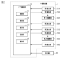
- FIG. 2 is an electrical block diagram of the door drive device according to the embodiment.
- 5A and 5B are diagrams illustrating a drive control of the door drive device according to the embodiment.
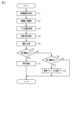
- 4 is a flowchart showing a drive control of the door drive device according to the embodiment.
- 5A and 5B are diagrams illustrating a drive control of the door drive device according to the embodiment.
- the door drive device is a device that drives a double swinging door to open and close.
- the door drive device 1 includes a door control device 10, a first drive unit 20A, a second drive unit 20B, and a first drive mechanism 30A and a second drive mechanism 30B.
- the door control device 10 controls the first drive unit 20A and the second drive unit 20B to open and close the first door 3 and the second door 4.
- Each of the first drive unit 20A and the second drive unit 20B is, for example, a motor, and outputs a drive force.
- the first drive mechanism 30A transmits the power of the first drive unit 20A to the first door 3.
- the second drive mechanism 30B transmits the power of the second drive unit 20B to the second door 4.
- the first drive unit 20A comprises a first drive shaft 22A, a first drive arm 23A, a first regulating plate 24A, a first fully open stopper 27A, and a first fully closed stopper 28A.
- the first drive shaft 22A is rotated by the first drive unit 20A.
- the first drive arm 23A and the first regulating plate 24A are integrally provided on the first drive shaft 22A.
- the first drive arm 23A extends on both sides from the first drive shaft 22A.
- the first regulating plate 24A comprises a first fully open regulating portion 25A and a first fully closed regulating portion 26A.
- the first fully open stopper 27A regulates the rotation of the first drive shaft 22A at the fully open position of the first door 3.
- the first full-close stopper 28A regulates the rotation of the first drive shaft 22A at the fully closed position of the first door 3.
- the first full-open stopper 27A and the first full-close stopper 28A are, for example, bolts.
- the first drive mechanism 30A includes a first connecting rod 31A, a first rotating shaft 32A, and a first rotating arm 33A.
- One end of the first connecting rod 31A is connected to one end of the first drive arm 23A.
- the other end of the first connecting rod 31A is connected to the first rotating arm 33A.
- the first rotating arm 33A is fixed to the first rotating shaft 32A and rotates integrally with the first rotating shaft 32A.
- the first rotating shaft 32A is fixed to the first door 3 and rotates integrally with the first door 3. Therefore, the first rotating arm 33A, the first rotating shaft 32A, and the first door 3 rotate integrally.
- the second drive unit 20B comprises a second drive shaft 22B, a second drive arm 23B, a second regulating plate 24B, a second fully open stopper 27B, and a second fully closed stopper 28B.
- the second drive shaft 22B is rotated by the second drive unit 20B.
- the second drive arm 23B and the second regulating plate 24B are integrally provided on the second drive shaft 22B.
- the second drive arm 23B extends on both sides from the second drive shaft 22B.
- the second regulating plate 24B comprises a second fully open regulating portion 25B and a second fully closed regulating portion 26B.
- the second fully open stopper 27B regulates the rotation of the second drive shaft 22B at the fully open position of the second door 4.
- the second full-close stopper 28B regulates the rotation of the second drive shaft 22B at the fully closed position of the second door 4.
- the second full-open stopper 27B and the second full-close stopper 28B are, for example, bolts.
- the second drive mechanism 30B includes a second connecting rod 31B, a second rotating shaft 32B, and a second rotating arm 33B.
- One end of the second connecting rod 31B is connected to one end of the second drive arm 23B.
- the other end of the second connecting rod 31B is connected to the second rotating arm 33B.
- the second rotating arm 33B is fixed to the second rotating shaft 32B and rotates integrally with the second rotating shaft 32B.
- the second rotating shaft 32B is fixed to the second door 4 and rotates integrally with the second door 4. Therefore, the second rotating arm 33B, the second rotating shaft 32B, and the second door 4 rotate integrally.
- the door control device 10 may be configured as one or more processors that execute various processes according to a computer program (software).
- the control method includes a setting step, a driving step, an acquisition step, and a change step, which will be described later.
- the door control device 10 may include one or more dedicated hardware circuits, such as an application specific integrated circuit (ASIC), that execute at least a part of the various processes.
- ASIC application specific integrated circuit
- the door control device 10 may be configured as 1) one or more processors that execute various processes according to a computer program (software), 2) one or more dedicated hardware circuits that execute at least a part of the various processes, or 3) a circuit (circuitry) that includes a combination thereof.
- the processor includes a CPU and memories such as a RAM and a ROM.
- the memory stores program code or instructions that are configured to cause the CPU to execute the processes.
- the memory i.e., a non-transitory computer-readable medium, includes any available medium that can be accessed by a general-purpose or dedicated computer.
- the program stored in the computer-readable medium includes a control program.
- the control program causes the door control device 10 to execute a setting step, a driving step, an obtaining step, and a changing step.
- the door control device 10 includes a control unit 11, an acquisition unit 12, a change unit 13, a storage unit 14, and an alarm unit 15.
- the control unit 11 controls the first drive unit 20A to open and close the first door 3, and controls the second drive unit 20B to open and close the second door 4.
- the acquisition unit 12 acquires the positions of the first door 3 and the second door 4 at a predetermined timing while the control unit 11 is controlling the multiple drive units.
- the change unit 13 changes the drive parameters for controlling the first drive unit 20A and the second drive unit 20B based on the acquisition result of the acquisition unit 12.
- the drive parameters are acceleration, speed, torque, distance, etc.
- the storage unit 14 stores the drive parameters and information related to the drive control performed by the control unit 11.
- the alarm unit 15 alerts the outside of a malfunction or abnormality using sound, light, display, etc.
- the door control device 10 can communicate with an operation terminal 40, and an installer can use the operation terminal 40 to operate settings related to door control.
- the installer can check notified malfunctions and abnormalities on the operation terminal 40.
- the installer can use the operation terminal 40 to set whether or not to enable stop control, which will be described later.
- the first driving unit 20A includes a first detection unit 21A.
- the first detection unit 21A is, for example, an encoder that detects the amount of rotation of the first driving unit 20A, processes the pulse count, and outputs the driving speed of the first door 3 to the door control device 10.
- the second driving unit 20B includes a second detection unit 21B.
- the second detection unit 21B is, for example, an encoder that detects the amount of rotation of the second driving unit 20B, processes the pulse count, and outputs the driving speed of the second door 4 to the door control device 10.
- the first detection unit 21A and the second detection unit 21B may output detection values such as pulse counts to the door control device 10, and the door control device 10 may calculate the driving speeds of the first door 3 and the second door 4.
- the acquisition unit 12 calculates the position of the first door 3 based on the driving speed of the first door 3 output from the first detection unit 21A.
- the acquisition unit 12 calculates the position of the second door 4 based on the driving speed of the second door 4 output from the second detection unit 21B.
- the control unit 11 switches the control states of the first drive unit 20A and the second drive unit 20B in the order of an acceleration control state, a high-speed control state, a deceleration control state, a low-speed control state, and a stop control state.
- the control unit 11 drives the first drive unit 20A and the second drive unit 20B in the same manner in the open drive and the close drive.
- the acceleration control state is a control state in which the drive speed is accelerated from the stopped state to the first speed V1.
- the time when the drive speed reaches the first speed V1 and the time when high-speed control starts is defined as the first time T1.
- the high-speed control state is a control state in which the drive speed is maintained at the first speed V1.
- the time when deceleration control starts is defined as the second time T2.
- the deceleration control state is a control state in which the drive speed is decelerated from the first speed V1 to the second speed V2.
- the time when the drive speed reaches the second speed V2 and the time when low-speed control starts is defined as the third time T3.
- the low-speed control state is a control state in which the drive speed is maintained at the second speed V2.
- the time when stop control starts is defined as the fourth time T4.
- the region from the third time T3 to the fourth time T4 in which low-speed control is performed is defined as the cushion region.
- the stop control state is a control state in which the drive speed is decelerated from the second speed V2 to stop.
- the control unit 11 controls the first drive unit 20A and the second drive unit 20B so that the control states of the first drive unit 20A and the second drive unit 20B are synchronized.
- the control unit 11 drives the first drive unit 20A and the second drive unit 20B with the same drive parameters.
- a deviation in operation timing may occur due to the installation position of the stopper, the characteristics of the motor, the assembly of the drive mechanism, etc. Therefore, the control unit 11 sets one of the first drive unit 20A and the second drive unit 20B as a reference drive unit. That is, the control unit 11 selects one of the first drive unit 20A and the second drive unit 20B as the reference drive unit.
- the control unit 11 controls the multiple drive units by controlling the other drive units based on the drive parameters for controlling the reference drive unit (drive parameters of the reference drive unit).
- the drive parameters of the reference drive unit are copied and stored in the memory unit 14 as drive parameters for controlling the other drive units (drive parameters of the other drive units).
- the change unit 13 changes the drive parameters of the other drive units so that the positions of these doors match.
- the change of the drive parameters is performed from the end of the current control of the drive unit to the start of the next drive control.
- the change of the drive parameters may be performed only during construction or inspection, or may be performed during normal drive control.
- the contractor or the like can select the reference drive unit using the operation terminal 40.
- the acquisition unit 12 acquires the positions of the first door 3 and the second door 4 at least one of the timings of the start of high-speed control (T1), the start of deceleration control (T2), the start of low-speed control (T3), and the end of low-speed control (T4).
- the notification unit 15 notifies the outside using sound, light, display, etc. when the difference in the positions of the first door 3 and the second door 4 is equal to or greater than a second threshold value that is greater than the first threshold value.
- the second threshold value corresponds to the notification threshold value.
- the door control device 10 sets a reference drive unit (step S1). That is, the control unit 11 sets one of the multiple drive units as a reference drive unit, and sets the drive parameters of the reference drive unit and drive parameters of the other drive units based on the drive parameters of the reference drive unit in the control unit 11. For example, an installer or the like operates the operation terminal 40 to select the drive unit to be set as the reference drive unit.
- the control unit 11 may arbitrarily select the drive unit to be set as the reference drive unit.
- the control unit 11 sets the reference drive unit, it copies the drive parameters of the reference drive unit and stores them in the memory unit 14 as drive parameters of the other drive units.
- Step S1 corresponds to a setting step.
- the door control device 10 performs the opening drive or closing drive (step S2). That is, the control unit 11 controls the drive of the first drive unit 20A and the second drive unit 20B with the same drive parameters. Step S2 corresponds to the drive step.
- the door control device 10 acquires the position of each door during driving, that is, the position of the door on the path from the fully open position to the fully closed position (or from the fully closed position to the fully open position) along which the door is driven (step S3). That is, the acquisition unit 12 acquires the positions of the first door 3 and the second door 4 at least one of the timings of the start of high-speed control, the start of deceleration control, the start of low-speed control, and the end of low-speed control.
- the position of the door driven by the reference drive unit is indicated by a solid line
- the position of the door driven by the other drive unit is indicated by a dashed line.
- Step S3 corresponds to an acquisition step.
- the door control device 10 acquires the difference in door positions (step S4). That is, the acquisition unit 12 acquires the difference between the positions of the first door 3 and the second door 4 at the same drive timing acquired in step S3.
- the door control device 10 compares the difference in the door positions with the threshold value (step S5). That is, the acquisition unit 12 compares the difference between the positions of the first door 3 and the second door 4 acquired in step S4 with the first threshold value and the second threshold value.
- the door control device 10 determines whether the difference in door positions is equal to or greater than the second threshold (step S6). That is, the control unit 11 checks whether the difference in door positions is so large that there is a possibility of an abnormality. Then, if the door control device 10 determines that the difference in door positions is equal to or greater than the second threshold (step S6: YES), it reports the abnormality (step S7). That is, the reporting unit 15 reports the abnormality to the outside.
- step S6 determines whether the difference in door positions is equal to or greater than the first threshold.
- the control unit 11 checks whether the difference in door positions is within a range that requires adjustment.
- step S8 NO
- the difference in door position is within the allowable range, meaning that no adjustment of the door position is necessary, and the process ends without changing the drive parameters.
- step S9 changes the drive parameters. That is, the change unit 13 changes the drive parameters of the other drive units that are the same as the drive parameters of the reference drive unit so that the position of the door driven by the reference drive unit matches the position of the door driven by the other drive unit. For example, in FIG. 5, the torque in acceleration control is lowered.
- the control unit 11 controls the drive units with the changed drive parameters from the next time they are driven. Step S9 corresponds to the change step.
- FIG. 2 A second embodiment of the door driving device will be described below with reference to Fig. 2.
- the door driving device of this embodiment differs from the first embodiment in that the detection unit directly detects the position of the door. The following description will focus on the differences from the first embodiment.
- the door drive device 1 includes a third detection unit 34A and a fourth detection unit 34B.
- the third detection unit 34A detects the position of the first door 3 during at least a portion of its movement and outputs the position to the door control device 10.
- the fourth detection unit 34B detects the position of the second door 4 during at least a portion of its movement and outputs the position to the door control device 10.
- the third detection unit 34A and the fourth detection unit 34B are, for example, a laser sensor, a magnetic sensor, a capacitance sensor, or a rotary sensor.
- the acquisition unit 12 acquires the position of the first door 3 by acquiring the detection result of the third detection unit 34A. Similarly, the acquisition unit 12 acquires the position of the second door 4 by acquiring the detection result of the fourth detection unit 34B.
- the change unit 13 changes the drive parameters of the other drive units so that the positions of these doors match. Since the drive parameters are changed based on the position of the door actually driven by the drive force transmitted from the drive unit, the operation timing of the doors can be further adjusted.
- the drive control in the change mode of the second embodiment is the same as the drive control of the first embodiment, except that the door position is detected by the third detection unit 34A and the fourth detection unit 34B, so a description of it will be omitted.
- the second embodiment has the following effects.
- (2-1) The actual position of each door is detected, and when the difference between the detected door positions is equal to or greater than a first threshold, the change unit 13 changes the drive parameters of the other drive units so that the positions of those doors match. Therefore, by further aligning the positions of the doors, the operation timing of the multiple doors can be further synchronized.
- the notification unit 15 may be omitted.
- the operation terminal 40 may be omitted.
- the drive parameters of the other drive units may be changed based on the difference in the door position in a plurality of drives, rather than the difference in the door position in one drive.
- the acquisition unit 12 acquires the door position at the timing when the control state of the drive unit is switched by the control unit 11.
- the acquisition unit 12 may acquire the door position at regular intervals.
- one control unit 11 drives and controls the first and second drive units 20A and 20B.
- a control unit may be provided for each drive unit, and each control unit may drive and control the drive unit.
- the drive parameters of the control unit that controls the drive unit set as the reference drive unit are copied as the drive parameters of the control unit that controls the other drive units. Therefore, even if two single-wing doors are installed in the other control unit and used as double-wing doors, the operation timing of each door can be synchronized.
- the drive unit performs both the opening drive and the closing drive.
- the drive unit may perform only one of the opening drive and the closing drive.
- the drive parameters are changed in a door drive device that drives a double swinging door to open and close so as to synchronize the operation timings of the doors.
- the drive parameters may be changed in a door drive device that drives a folding door to open and close so as to synchronize the operation timings of the doors.
- one of the drive units of one opening may be set as a reference drive unit, and the drive parameters of the other drive units of the opening and the drive units of the doors of the other openings may be changed so as to synchronize the operation timings of the doors of the respective openings.
- an encoder provided in the drive unit or a detection unit that directly detects the position of the door is used as the acquisition unit.
- a start sensor of the door drive device may also be used as the detection unit.
- the detection unit is, for example, an infrared sensor or an image sensor.
- the multiple objects may be integrated together, and conversely, if something is made up of a single object, it may be divided into multiple objects. Regardless of whether they are integrated or not, it is sufficient that the object of this disclosure can be achieved.
Landscapes
- Power-Operated Mechanisms For Wings (AREA)
Abstract
Description
上記課題を解決するドア駆動装置の制御方法は、複数のドアを駆動する複数の駆動部と、前記複数の駆動部を制御する制御部と、前記複数のドアの位置を取得する取得部と、前記取得部による取得結果に基づいて前記駆動部を制御するための駆動パラメータを変更する変更部と、を備えるドア駆動装置の制御方法であって、前記複数の駆動部のうちの一つを基準駆動部として設定し、前記基準駆動部を制御するための駆動パラメータと前記基準駆動部を制御するための駆動パラメータに基づく他の駆動部を制御するための駆動パラメータとを前記制御部に設定する設定ステップと、前記制御部が前記複数の駆動部を駆動制御する駆動ステップと、前記制御部による前記複数の駆動部の制御中の所定タイミングでの前記複数のドアの位置を前記取得部が取得する取得ステップと、前記取得ステップにおいて取得した前記基準駆動部が駆動するドアの位置と前記他の駆動部が駆動するドアの位置との差が閾値以上のときに、前記他の駆動部を駆動するドアの位置が前記基準駆動部が駆動するドアの位置と一致するように前記他の駆動部を制御するための駆動パラメータを前記変更部が変更する変更ステップと、を含む。
以下、図1~図5を参照して、ドア駆動装置の第1実施形態について説明する。ドア駆動装置は、両開き戸を開閉駆動する装置である。
図2に示すように、ドア制御装置10は、コンピュータプログラム(ソフトウェア)に従って各種処理を実行する1つ以上のプロセッサとして構成し得る。ドア制御装置10すなわちプロセッサにより実行される処理には、制御方法が含まれる。制御方法は、後述する設定ステップと駆動ステップと取得ステップと変更ステップとを含む。なお、ドア制御装置10は、各種処理のうち少なくとも一部の処理を実行する、特定用途向け集積回路(ASIC)等の1つ以上の専用のハードウェア回路を備えてもよい。すなわち、ドア制御装置10は、1)コンピュータプログラム(ソフトウェア)に従って各種処理を実行する1つ以上のプロセッサ、2)各種処理のうち少なくとも一部の処理を実行する1つ以上の専用のハードウェア回路、または3)それらの組み合わせを含む回路(circuitry)として構成されてもよい。プロセッサは、CPU及び、RAM並びにROM等のメモリを含む。メモリは、処理をCPUに実行させるように構成されたプログラムコードまたは指令を格納している。メモリすなわち非一時的なコンピュータ可読媒体は、汎用または専用のコンピュータでアクセスできるあらゆる利用可能な媒体を含む。コンピュータ可読媒体に格納されたプログラムには制御プログラムが含まれる。制御プログラムは、設定ステップと駆動ステップと取得ステップと変更ステップとをドア制御装置10に実行させる。
次に、図3を参照して、ドア駆動装置1による開閉駆動について説明する。
図3に示すように、制御部11は、第1駆動部20A及び第2駆動部20Bの各々の制御状態を、加速制御状態、高速制御状態、減速制御状態、低速制御状態、停止制御状態の順に切り替える。制御部11は、開駆動及び閉駆動で同じように第1駆動部20A及び第2駆動部20Bを駆動する。
次に、図4を併せ参照して、変更モードにおける上記ドア駆動装置1の駆動制御について説明する。駆動量を変更する際には、施工者が操作端末40を操作して、ドア駆動装置1を通常モードから変更モードに切り替える。
(1-1)基準駆動部が駆動するドアの位置と他の駆動部が駆動するドアの位置との差が閾値以上のときに、他の駆動部の駆動パラメータをそれらのドアの位置が一致するように変更部13が変更する。このため、各ドアの位置を合わせることで複数のドアの作動タイミングを合わせることができる。
以下、図2を併せ参照して、ドア駆動装置の第2実施形態について説明する。この実施形態のドア駆動装置は、ドアの位置を検出部が直接検出する点において上記第1実施形態と異なっている。以下、第1実施形態との相違点を中心に説明する。
(2-1)各ドアの実際の位置を検出して、検出されたドアの位置の差が第1閾値以上のときに、他の駆動部の駆動パラメータをそれらのドアの位置が一致するように変更部13が変更する。このため、各ドアの位置を更に合わせることで複数のドアの作動タイミングを更に合わせることができる。
上記各実施形態は、以下のように変更して実施することができる。上記各実施形態及び以下の変更例は、技術的に矛盾しない範囲で互いに組み合わせて実施することができる。
・上記各実施形態において、操作端末40を省略してもよい。
・上記各実施形態において、1回の駆動におけるドアの位置の差ではなく、複数回の駆動におけるドアの位置の差に基づいて他の駆動部の駆動パラメータを変更してもよい。
・上記各実施形態では、両開き戸を開閉駆動するドア駆動装置においてドア同士の作動タイミングを合わせるように駆動パラメータを変更した。しかしながら、折戸を開閉駆動するドア駆動装置においてドア同士の作動タイミングを合わせるように駆動パラメータを変更してもよい。また、異なる開口のドアを各々開閉駆動する複数のドア駆動装置において、いずれか1開口の複数の駆動部のうちの1つを基準駆動部とし、それぞれの開口のドア同士の作動タイミングを合わせるように当該開口の他の駆動部とその他の開口のドアの各駆動部の駆動パラメータを変更してもよい。
2…ケース
3…第1ドア
4…第2ドア
10…ドア制御装置
11…制御部
12…取得部
13…変更部
14…記憶部
15…報知部
20A…第1駆動部
20B…第2駆動部
21A…第1検出部
21B…第2検出部
22A…第1駆動軸
22B…第2駆動軸
23A…第1駆動アーム
23B…第2駆動アーム
24A…第1規制板
24B…第2規制板
25A…第1全開規制部
25B…第2全開規制部
26A…第1全閉規制部
26B…第2全閉規制部
27A…第1全開ストッパ
27B…第2全開ストッパ
28A…第1全閉ストッパ
28B…第2全閉ストッパ
30A…第1駆動機構
30B…第2駆動機構
31A…第1連結棒
31B…第2連結棒
32A…第1回転軸
32B…第2回転軸
33A…第1回転アーム
33B…第2回転アーム
34A…第3検出部
34B…第4検出部
40…操作端末
Claims (5)
- 複数のドアをそれぞれ駆動する複数の駆動部と、
前記複数の駆動部の一つを基準駆動部に設定し、前記基準駆動部を制御するための駆動パラメータに基づいて他の駆動部を制御することによって、前記複数の駆動部を制御する制御部と、
前記制御部による前記複数の駆動部の制御中の所定タイミングでの前記複数のドアの位置を取得する取得部と、
前記取得部が取得した前記基準駆動部が駆動するドアの位置と前記他の駆動部が駆動するドアの位置との差が閾値以上のときに、前記他の駆動部を駆動するドアの位置が前記基準駆動部が駆動するドアの位置と一致するように前記他の駆動部を制御するための駆動パラメータを変更する変更部と、を備える
ドア駆動装置。 - 前記制御部は、前記複数の駆動部の各々の制御状態を、前記ドアの駆動速度が第1速度に加速される加速制御状態と、前記駆動速度が前記第1速度に維持される高速制御状態と、前記駆動速度が前記第1速度よりも低い第2速度に減速される減速制御状態と、前記駆動速度が前記第2速度に維持される低速制御状態との間で切り替え、
前記取得部は、前記高速制御状態の開始時、前記減速制御状態の開始時、前記低速制御状態の開始時、前記低速制御状態の終了時のうちの少なくとも一つのタイミングで前記複数のドアの位置を取得する
請求項1に記載のドア駆動装置。 - 前記差が前記閾値よりも大きい報知閾値以上であるときに外部に報知する報知部を備える
請求項1又は2に記載のドア駆動装置。 - 複数のドアを駆動する複数の駆動部と、
前記複数の駆動部を制御する制御部と、
前記複数のドアの位置を取得する取得部と、
前記取得部による取得結果に基づいて前記駆動部を制御するための駆動パラメータを変更する変更部と、を備えるドア駆動装置の制御方法であって、
前記複数の駆動部のうちの一つを基準駆動部として設定し、前記基準駆動部を制御するための駆動パラメータと前記基準駆動部を制御するための駆動パラメータに基づく他の駆動部を制御するための駆動パラメータとを前記制御部に設定する設定ステップと、
前記制御部が前記複数の駆動部を駆動制御する駆動ステップと、
前記制御部による前記複数の駆動部の制御中の所定タイミングでの前記複数のドアの位置を前記取得部が取得する取得ステップと、
前記取得ステップにおいて取得した前記基準駆動部が駆動するドアの位置と前記他の駆動部が駆動するドアの位置との差が閾値以上のときに、前記他の駆動部を駆動するドアの位置が前記基準駆動部が駆動するドアの位置と一致するように前記他の駆動部を制御するための駆動パラメータを前記変更部が変更する変更ステップと、を含む
ドア駆動装置の制御方法。 - 複数のドアを駆動する複数の駆動部と、
前記複数の駆動部を制御する制御部と、
前記複数のドアの位置を取得する取得部と、
前記取得部による取得結果に基づいて前記駆動部を制御するための駆動パラメータを変更する変更部と、を備えるドア駆動装置の制御プログラムであって、
前記複数の駆動部のうちの一つを基準駆動部として設定し、前記基準駆動部を制御するための駆動パラメータと前記基準駆動部を制御するための駆動パラメータに基づく他の駆動部を制御するための駆動パラメータとを前記制御部に設定する設定ステップと、
前記制御部が前記複数の駆動部を駆動制御する駆動ステップと、
前記制御部による前記複数の駆動部の制御中の所定タイミングでの前記複数のドアの位置を前記取得部が取得する取得ステップと、
前記取得ステップにおいて取得した前記基準駆動部が駆動するドアの位置と前記他の駆動部が駆動するドアの位置との差が閾値以上のときに、前記他の駆動部を駆動するドアの位置が前記基準駆動部が駆動するドアの位置と一致するように前記他の駆動部を制御するための駆動パラメータを前記変更部が変更する変更ステップと、をコンピュータが実行する
ドア駆動装置の制御プログラム。
Priority Applications (1)
| Application Number | Priority Date | Filing Date | Title |
|---|---|---|---|
| JP2025518144A JPWO2024228367A1 (ja) | 2023-05-01 | 2024-04-26 |
Applications Claiming Priority (2)
| Application Number | Priority Date | Filing Date | Title |
|---|---|---|---|
| JP2023-075783 | 2023-05-01 | ||
| JP2023075783 | 2023-05-01 |
Publications (1)
| Publication Number | Publication Date |
|---|---|
| WO2024228367A1 true WO2024228367A1 (ja) | 2024-11-07 |
Family
ID=93332993
Family Applications (1)
| Application Number | Title | Priority Date | Filing Date |
|---|---|---|---|
| PCT/JP2024/016413 Ceased WO2024228367A1 (ja) | 2023-05-01 | 2024-04-26 | ドア駆動装置、ドア駆動装置の制御方法、及びドア駆動装置の制御プログラム |
Country Status (2)
| Country | Link |
|---|---|
| JP (1) | JPWO2024228367A1 (ja) |
| WO (1) | WO2024228367A1 (ja) |
Citations (3)
| Publication number | Priority date | Publication date | Assignee | Title |
|---|---|---|---|---|
| JP2005273327A (ja) * | 2004-03-25 | 2005-10-06 | Chikura Kogyo Kk | 自動ドアの駆動装置 |
| WO2020031833A1 (ja) * | 2018-08-09 | 2020-02-13 | ナブテスコ株式会社 | 自動ドア保守支援システム、自動ドア保守支援装置、自動ドア装置、自動ドア保守支援方法、プログラム |
| JP2022154565A (ja) * | 2021-03-30 | 2022-10-13 | 株式会社京三製作所 | ホーム柵状態監視装置及びホーム柵状態監視方法 |
-
2024
- 2024-04-26 WO PCT/JP2024/016413 patent/WO2024228367A1/ja not_active Ceased
- 2024-04-26 JP JP2025518144A patent/JPWO2024228367A1/ja active Pending
Patent Citations (3)
| Publication number | Priority date | Publication date | Assignee | Title |
|---|---|---|---|---|
| JP2005273327A (ja) * | 2004-03-25 | 2005-10-06 | Chikura Kogyo Kk | 自動ドアの駆動装置 |
| WO2020031833A1 (ja) * | 2018-08-09 | 2020-02-13 | ナブテスコ株式会社 | 自動ドア保守支援システム、自動ドア保守支援装置、自動ドア装置、自動ドア保守支援方法、プログラム |
| JP2022154565A (ja) * | 2021-03-30 | 2022-10-13 | 株式会社京三製作所 | ホーム柵状態監視装置及びホーム柵状態監視方法 |
Also Published As
| Publication number | Publication date |
|---|---|
| JPWO2024228367A1 (ja) | 2024-11-07 |
Similar Documents
| Publication | Publication Date | Title |
|---|---|---|
| US12428897B2 (en) | Sectional door operator system | |
| KR910021335A (ko) | 엘리베이터의 도어제어장치 | |
| JPH11270226A (ja) | パワーウインド装置の挟み込み検知方法 | |
| US6646399B2 (en) | Controller for shutting apparatus | |
| JP2547344B2 (ja) | 電動モータ回転速度を調整する方法及びモータの回転速度調整装置 | |
| CN117549839A (zh) | 吸顶屏控制方法、系统、电子设备及介质 | |
| JP5182694B2 (ja) | エレベータのドア制御装置 | |
| WO2024219315A1 (ja) | ドア駆動装置、ドア駆動装置の制御方法、及びドア駆動装置の制御プログラム | |
| KR101844200B1 (ko) | 엘리베이터 도어 개폐 장치 및 엘리베이터 도어 개폐 장치의 개수 방법 | |
| JP6610397B2 (ja) | 開閉体駆動モータ | |
| WO2022105885A1 (zh) | 一种由电机驱动的机构确定开关时间的方法及系统 | |
| JP2024160600A (ja) | ドア駆動装置、ドア駆動装置の制御方法、及びドア駆動装置の制御プログラム | |
| JP7141969B2 (ja) | 開閉体制御装置、車両、開閉体制御方法、及び開閉体制御プログラム | |
| JPH03186589A (ja) | エレベータ扉の制御装置 | |
| CN111365823A (zh) | 空调系统及空调系统的控制方法 | |
| JP7704539B2 (ja) | ドア施工診断支援装置、ドア施工診断支援方法、プログラム | |
| US10954708B2 (en) | Movable barrier opener with brushless DC motor | |
| JP2004162364A (ja) | 開閉システム | |
| JPH10250571A (ja) | ドア用開閉装置 | |
| JP2000143133A (ja) | エレベータドアの制御装置 | |
| US12179565B2 (en) | Mobile body moving device | |
| JP5344887B2 (ja) | エレベータのドア制御装置 | |
| JP2020111938A (ja) | 開閉部材制御装置 | |
| JP2024132273A (ja) | ドア駆動装置、ドア駆動装置の調整方法、及びドア駆動装置の調整プログラム | |
| JP2010208776A (ja) | エレベータのドア制御装置 |
Legal Events
| Date | Code | Title | Description |
|---|---|---|---|
| 121 | Ep: the epo has been informed by wipo that ep was designated in this application |
Ref document number: 24800098 Country of ref document: EP Kind code of ref document: A1 |
|
| ENP | Entry into the national phase |
Ref document number: 2025518144 Country of ref document: JP Kind code of ref document: A |
|
| WWE | Wipo information: entry into national phase |
Ref document number: 2025518144 Country of ref document: JP |
|
| NENP | Non-entry into the national phase |
Ref country code: DE |
|
| 122 | Ep: pct application non-entry in european phase |
Ref document number: 24800098 Country of ref document: EP Kind code of ref document: A1 |