WO2024228337A1 - 車両用エアバッグ制御システム及び車両用エアバッグ制御システムの動作方法 - Google Patents
車両用エアバッグ制御システム及び車両用エアバッグ制御システムの動作方法 Download PDFInfo
- Publication number
- WO2024228337A1 WO2024228337A1 PCT/JP2024/015531 JP2024015531W WO2024228337A1 WO 2024228337 A1 WO2024228337 A1 WO 2024228337A1 JP 2024015531 W JP2024015531 W JP 2024015531W WO 2024228337 A1 WO2024228337 A1 WO 2024228337A1
- Authority
- WO
- WIPO (PCT)
- Prior art keywords
- seat
- vehicle
- airbag control
- control system
- sensor
- Prior art date
- Legal status (The legal status is an assumption and is not a legal conclusion. Google has not performed a legal analysis and makes no representation as to the accuracy of the status listed.)
- Ceased
Links
Images





Classifications
-
- B—PERFORMING OPERATIONS; TRANSPORTING
- B60—VEHICLES IN GENERAL
- B60N—SEATS SPECIALLY ADAPTED FOR VEHICLES; VEHICLE PASSENGER ACCOMMODATION NOT OTHERWISE PROVIDED FOR
- B60N2/00—Seats specially adapted for vehicles; Arrangement or mounting of seats in vehicles
- B60N2/02—Seats specially adapted for vehicles; Arrangement or mounting of seats in vehicles the seat or part thereof being movable, e.g. adjustable
- B60N2/0224—Non-manual adjustments, e.g. with electrical operation
- B60N2/0244—Non-manual adjustments, e.g. with electrical operation with logic circuits
- B60N2/0272—Non-manual adjustments, e.g. with electrical operation with logic circuits using sensors or detectors for detecting the position of seat parts
-
- B—PERFORMING OPERATIONS; TRANSPORTING
- B60—VEHICLES IN GENERAL
- B60N—SEATS SPECIALLY ADAPTED FOR VEHICLES; VEHICLE PASSENGER ACCOMMODATION NOT OTHERWISE PROVIDED FOR
- B60N2/00—Seats specially adapted for vehicles; Arrangement or mounting of seats in vehicles
- B60N2/005—Arrangement or mounting of seats in vehicles, e.g. dismountable auxiliary seats
- B60N2/01—Arrangement of seats relative to one another
-
- B—PERFORMING OPERATIONS; TRANSPORTING
- B60—VEHICLES IN GENERAL
- B60R—VEHICLES, VEHICLE FITTINGS, OR VEHICLE PARTS, NOT OTHERWISE PROVIDED FOR
- B60R21/00—Arrangements or fittings on vehicles for protecting or preventing injuries to occupants or pedestrians in case of accidents or other traffic risks
- B60R21/01—Electrical circuits for triggering passive safety arrangements, e.g. airbags, safety belt tighteners, in case of vehicle accidents or impending vehicle accidents
-
- B—PERFORMING OPERATIONS; TRANSPORTING
- B60—VEHICLES IN GENERAL
- B60R—VEHICLES, VEHICLE FITTINGS, OR VEHICLE PARTS, NOT OTHERWISE PROVIDED FOR
- B60R21/00—Arrangements or fittings on vehicles for protecting or preventing injuries to occupants or pedestrians in case of accidents or other traffic risks
- B60R21/01—Electrical circuits for triggering passive safety arrangements, e.g. airbags, safety belt tighteners, in case of vehicle accidents or impending vehicle accidents
- B60R21/013—Electrical circuits for triggering passive safety arrangements, e.g. airbags, safety belt tighteners, in case of vehicle accidents or impending vehicle accidents including means for detecting collisions, impending collisions or roll-over
-
- B—PERFORMING OPERATIONS; TRANSPORTING
- B60—VEHICLES IN GENERAL
- B60R—VEHICLES, VEHICLE FITTINGS, OR VEHICLE PARTS, NOT OTHERWISE PROVIDED FOR
- B60R21/00—Arrangements or fittings on vehicles for protecting or preventing injuries to occupants or pedestrians in case of accidents or other traffic risks
- B60R21/01—Electrical circuits for triggering passive safety arrangements, e.g. airbags, safety belt tighteners, in case of vehicle accidents or impending vehicle accidents
- B60R21/015—Electrical circuits for triggering passive safety arrangements, e.g. airbags, safety belt tighteners, in case of vehicle accidents or impending vehicle accidents including means for detecting the presence or position of passengers, passenger seats or child seats, and the related safety parameters therefor, e.g. speed or timing of airbag inflation in relation to occupant position or seat belt use
- B60R21/01512—Passenger detection systems
-
- B—PERFORMING OPERATIONS; TRANSPORTING
- B60—VEHICLES IN GENERAL
- B60R—VEHICLES, VEHICLE FITTINGS, OR VEHICLE PARTS, NOT OTHERWISE PROVIDED FOR
- B60R21/00—Arrangements or fittings on vehicles for protecting or preventing injuries to occupants or pedestrians in case of accidents or other traffic risks
- B60R21/01—Electrical circuits for triggering passive safety arrangements, e.g. airbags, safety belt tighteners, in case of vehicle accidents or impending vehicle accidents
- B60R21/015—Electrical circuits for triggering passive safety arrangements, e.g. airbags, safety belt tighteners, in case of vehicle accidents or impending vehicle accidents including means for detecting the presence or position of passengers, passenger seats or child seats, and the related safety parameters therefor, e.g. speed or timing of airbag inflation in relation to occupant position or seat belt use
- B60R21/01512—Passenger detection systems
- B60R21/01516—Passenger detection systems using force or pressure sensing means
-
- B—PERFORMING OPERATIONS; TRANSPORTING
- B60—VEHICLES IN GENERAL
- B60R—VEHICLES, VEHICLE FITTINGS, OR VEHICLE PARTS, NOT OTHERWISE PROVIDED FOR
- B60R21/00—Arrangements or fittings on vehicles for protecting or preventing injuries to occupants or pedestrians in case of accidents or other traffic risks
- B60R21/01—Electrical circuits for triggering passive safety arrangements, e.g. airbags, safety belt tighteners, in case of vehicle accidents or impending vehicle accidents
- B60R21/015—Electrical circuits for triggering passive safety arrangements, e.g. airbags, safety belt tighteners, in case of vehicle accidents or impending vehicle accidents including means for detecting the presence or position of passengers, passenger seats or child seats, and the related safety parameters therefor, e.g. speed or timing of airbag inflation in relation to occupant position or seat belt use
- B60R21/01554—Seat position sensors
-
- B—PERFORMING OPERATIONS; TRANSPORTING
- B60—VEHICLES IN GENERAL
- B60R—VEHICLES, VEHICLE FITTINGS, OR VEHICLE PARTS, NOT OTHERWISE PROVIDED FOR
- B60R21/00—Arrangements or fittings on vehicles for protecting or preventing injuries to occupants or pedestrians in case of accidents or other traffic risks
- B60R21/01—Electrical circuits for triggering passive safety arrangements, e.g. airbags, safety belt tighteners, in case of vehicle accidents or impending vehicle accidents
- B60R2021/01034—Controlling a plurality of restraint devices
Definitions
- the present invention relates to a vehicle airbag control system and a method for operating the vehicle airbag control system.
- Airbags are operable in response to an airbag control unit.
- the airbag control unit is capable of determining that a crash impact has occurred by monitoring various vehicle sensors, including an accelerometer. If a crash is determined to be in progress, the airbag control unit outputs an activation signal to rapidly inflate the airbag, thereby providing cushioning and restraint to vehicle occupants in the event of an accident.
- Airbags may be mounted in multiple locations, including but not limited to the dashboard or steering wheel of the vehicle, door panels, cant rails, seats, center console, etc.
- the vehicle has multiple airbags, only a portion of the airbags installed in the vehicle may be inflated depending on the nature of the detected impact.
- the seats can be rearranged.
- some or all of the seats can be rotated or rearranged to face inward or backward. Changing the seat position or orientation (or, indeed, seat occupancy) can alter the airbag deployment appropriate for a particular accident.
- the object of the present invention is to provide an airbag control system and an operating method of the airbag control system suitable for use in a vehicle with a changeable seating configuration or seat usage.
- a vehicle airbag control system includes a plurality of airbags mounted in a vehicle, one or more seat occupancy sensors, one or more seat configuration sensors, one or more crash sensors, and an airbag control unit that outputs an airbag activation signal to one or more of the plurality of airbags.
- the airbag control unit determines the seat occupancy of the vehicle using the seat occupancy sensor, the seat configuration sensor, and the crash sensor, determines whether a vehicle crash has occurred, and classifies the determined crash.
- the airbag activation signal is modified and output according to the determined classification of the crash, the determined vehicle seat occupancy, and the determined vehicle seat configuration.
- the present invention makes it possible to provide airbag activation appropriate to the determined collision accident, even if the vehicle's seating configuration or seat usage is changed.
- FIG. 1 is a perspective view showing a vehicle in which a vehicle airbag control system according to an embodiment is installed.
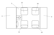
- FIG. 2 is a schematic diagram showing a seat layout in a vehicle.
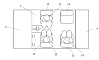
- FIG. 3A is a schematic diagram showing an airbag installation position inside a vehicle.
- FIG. 3B is a schematic diagram showing crash sensor and seat occupancy sensor locations within the interior of the vehicle.
- FIG. 4A is a schematic diagram showing a reconfigured seating layout.
- FIG. 4B is a schematic diagram showing an occupant within the seating layout of FIG. 4A.
- FIG. 4C is a schematic diagram illustrating another reconfigured seating layout.
- FIG. 4D is a schematic diagram showing an occupant within the seating layout of FIG. 4C.
- FIG. 5A is a schematic front view showing a reconfigurable seat.
- FIG. 5A is a schematic front view showing a reconfigurable seat.
- FIG. 5B is a schematic side view showing a reconfigurable seat.
- FIG. 5C is a schematic bottom view of a reconfigurable seat.
- FIG. 5D is a schematic cross-sectional view showing a socket for receiving the plug protruding from the seat shown in FIGS. 5A-5C.
- FIG. 5E is a schematic diagram showing the location of a socket that receives the plug protruding from the seat shown in FIGS. 5A-5C.
- FIG. 6 is a block diagram showing the configuration of a vehicle airbag control system according to the embodiment.
- FIG. 1 shows a vehicle 1 provided with an electric motor or an internal combustion engine powering road wheels 2.
- the vehicle 1 comprises a front compartment 3, which houses an electric motor or an internal combustion engine (neither shown). If an electric motor is provided, the front compartment 3 may also comprise a flank, which is a storage space. Furthermore, the vehicle 1 comprises a rear compartment 4, which may for example be in the form of a trunk providing storage space.
- the vehicle 1 also comprises a passenger compartment 5, which can be accessed through a door 6 (see FIG. 1).
- the vehicle 1 is provided with a number of airbags 30 that are operable to inflate in response to the detection of a collision involving the vehicle 1 to protect the occupants 21-24 (see Figures 2, 3A, and 6).
- the multiple airbags may be collectively referred to as airbag 30, or the individual airbags may be referred to as airbags 31a-39, etc.
- FIG. 2 shows a schematic plan view of the interior of vehicle 1.
- Passenger compartment 5 includes seats 11-14.
- an optional center seat 15 can be provided in the second row, and seats 13-15 can be replaced with bench-style seats.
- a vehicle having only two seats 13, 14 in the second row will be described.
- passenger 21 who drives the vehicle
- a steering wheel 17 in front of seat 11 which is the driver's seat
- a gear selector console 16 Note that the number and arrangement of seats 11-14, the position of passenger 21 who drives the vehicle, and the position of steering wheel 17 are not limited to those described above.
- the vehicle 1 is fitted with a number of airbags 31a-39 operable to protect the occupants 21-24 by inflating in response to the detection of a crash involving the vehicle 1 (see Figs. 3A and 6).
- the embodiment shown in Fig. 3A includes lateral airbags 31a, 31b, 32a, 32b, 33a, 33b, 34a and 34b fitted to each of the seats 11-14.
- the vehicle 1 also includes a steering wheel airbag 35, a dashboard airbag 36, front door airbags 37a, 37b, rear door airbags 38a, 38b and seatback airbags 39 on the backs of the front seats 11, 12.
- the number and arrangement of the airbags 30 are not limited to those described above.
- the operation of the airbags 30, which are part of the airbag control system 100 according to the embodiment, is controlled by an airbag control unit 101 in response to various sensors described below (see FIG. 6).
- the airbag control unit 101 may be operable to output activation signals to all or some of the airbags 30 in response to a classification of a detected crash event.
- airbags 35, 36 and 39 may be activated in response to a crash event involving a frontal collision.
- airbags 31b, 32a, 33b, 34a, 37b and 38b may be activated in a crash event involving a crash from the right side of the vehicle 1.
- Airbags 31a, 32b, 33a, 34b, 37a and 38a may be activated in a crash event involving a crash from the left side of the vehicle 1. More or different combinations of airbags 30 may be activated in more severe or more complex crash events. This allows the airbag control unit 101 to activate sufficient airbags 30 to protect the occupants 21-24 in the detected collision, without activating airbags 30 that may have a negative effect on the protection of the occupants 21-24 or airbags 30 that are not necessary for protection. This allows the occupants 21-24 to be appropriately protected, while reducing the cost of replacing activated airbags 30.
- the vehicle 1 is fitted with multiple crash sensors 40 (see Figures 3B and 6).
- a primary accelerometer 41 is provided near the gear selector console 16.
- the primary accelerometer 41 can provide an output indicative of the acceleration (acceleration or deceleration) experienced by a central portion of the vehicle 1.
- the vehicle 1 may be fitted with one or more satellite accelerometers 43a-44b to determine the acceleration experienced by different portions of the vehicle 1. The difference in acceleration measured by the primary accelerometer 41 and the satellite accelerometers helps classify the crash event.
- a pair of satellite accelerometers 43a, 43b are provided in the front compartment 3, and a pair of satellite accelerometers 44a, 44b are provided in the rear compartment 4.
- the number and arrangement of the satellite accelerometers 43a-44b are not limited to the above, and they may be located in the engine compartment or the flank.
- the crash sensor 40 may include impact sensors such as front door mounted impact sensors 45a, 45b and rear door mounted impact sensors 46a, 46b. Additional or alternative crash sensors 40 may be provided including, but not limited to, pressure sensors, wheel speed sensors, brake sensors, gyroscopes, etc.
- the seat occupancy sensor 50 may include pressure pads 51-54 mounted to the occupant support surface of the seat 11-14 and operable to sense the weight of the occupant 21-24 (see Figs. 3B, 6).
- the seat occupancy sensor 50 may also include cameras 55a, 55b, 56a, 56b, 57a, 57b, 58a, 58b operable to capture images of the seat 11-14 and thereby determine whether the seat 11-14 is occupied.
- the cameras 55a-58b may be operable in any suitable wavelength band, including visible or infrared light.
- the types and combinations of sensors are not limited to the above and may be combined with other forms of seat occupancy sensor 50, including lidar or radar sensors.
- the output of the seat occupancy sensor 50 may be used by the airbag control unit 101 in determining whether a particular airbag 30 needs to be deployed in a particular crash event. For example, if the seat occupancy sensor 50 detects that the seats 13 and 14 are not occupied, it may not be necessary to deploy any of the airbags 33a, 33b, 34a, 34b, 38a, 38b, or 39.
- seats 11-14 are reconfigurable.
- the seat orientation can be changed as illustrated in Figures 4A-4D.
- seat 12 for front occupant 22 is rotated to face rearward.
- the remaining seats 11, 13, 14 are in a forward-facing configuration. This allows front occupant 22 to directly face occupants 23, 24 in rear seats 13, 14, as shown in Figure 4B.
- each of the seats 11-14 is rotated to face inward. This allows the occupants 21-23 to face each other as shown in FIG. 4D.
- the configuration of the seats 11-14 is not limited to the above, and seats can be configured to face forward, backward, inward, or outward, or they can be arranged diagonally between any of these directions. It is also possible to change the position of the seats 11-14 in the vehicle 1 inside the passenger compartment 5 in the vertical or horizontal direction.
- the alternative seating configuration involving a change in the orientation of the driver's seat 11 may be used, for example, only when the vehicle 1 is stationary or when the vehicle 1 is adapted to perform autonomous driving. If any of the seats 11-14 are not in a forward-facing orientation when a crash event is detected, deployment of the airbag 30 based on a forward-facing seat orientation may not be appropriate.
- a number of seat occupancy sensors 50 such as cameras 55a-58b (or radar sensors, lidar sensors), may be used to additionally determine the seat configuration (orientation and position).
- a separate seat configuration sensor 80 is provided, as described below.
- Each seat has a generally upright portion, or backrest 61, and a horizontal portion, or cushion 62 (see Figures 5A and 5B).
- the occupant 21-24 sits on the upper surface 63 of the cushion 62.
- One or more plugs 65 may protrude from the base, or lower surface 64, of the cushion 62.
- the seat may also have other structural elements necessary to secure the seat in a fixed position relative to the floor 70 of the passenger compartment 5.
- the floor 70 is a floor panel and includes a number of sockets 71a-74b that receive the plugs 65 from each seat.
- one set of sockets 71a receives the plugs 65 when the seat is placed in a driving position facing forward or rearward
- another set of sockets 71b receives the plugs 65 when the seat is placed in a driving position facing inward or outward
- two sets of sockets 72a, 72b are provided for the front passenger positions
- two sets of sockets 73a, 73b and 74a, 74b are provided corresponding to the two rear seat positions.
- a seat configuration sensor 80 may be provided within each socket 71a-74b.
- the seat configuration sensor 80 may detect the insertion of a plug 65 into a corresponding socket 71a-74b.
- the seat configuration sensor 80 may be operable to identify a particular plug 65 (e.g., a front or rear plug) to determine whether the seat is facing forward, backward, inward, or outward.
- the seat configuration sensor 80 may include a pressure sensor, a push switch, a reed switch, a proximity switch, an RFID sensor, or the like. The seat position and orientation may be determined where the plug 65 can only engage with the socket 71a-74b when the seat is properly secured in place relative to the socket 71a-74b.
- a cover 75 may also be provided to prevent the socket 71a-74b from being blocked by debris or damaged by children or pets.
- the lid 75 can be rotated, for example, around a suitable axis 76 and is biased to the closed position by a biasing member 77 such as a spring.
- FIG. 6 shows a block diagram illustrating the configuration of an airbag control system 100 according to an embodiment.
- the airbag control unit 101 is connected to the collision sensor 40, the seat occupancy sensor 50, and the seat configuration sensor 80, and can receive signals from each of the collision sensor 40, the seat occupancy sensor 50, and the seat configuration sensor 80.
- the airbag control unit 101 is connected to the airbags 30, and can output an activation signal to inflate one or more of the airbags 30 when necessary.
- the airbag control unit 101 may process signals received from the seat configuration sensor 80 to determine the seat configuration of the vehicle 1.
- the airbag control unit 101 may be operable to output an alarm if it determines that a seat 11-14 is missing or partially or incorrectly installed.
- the airbag control unit 101 may be operable to process signals received from the seat occupancy sensor 50 to determine whether each seat 11-14 is occupied.
- the seat configuration and seat occupancy data may be output to a user interface 102.
- the user interface 102 may be, for example, a dashboard display screen in the vehicle 1, allowing the occupants 21-24 to verify that the data is accurate.
- additional sensors such as seat belt sensors are installed in the vehicle 1, data from these sensors may also be processed by the airbag control unit 101 and output via the user interface 102.
- the airbag control unit 101 can process the output of the collision sensors 40 to determine whether a collision has occurred. For one or more collision sensors 40, the determination can be made from a sensor output indicating that the acceleration or deceleration of the vehicle 1 has exceeded a predetermined threshold, or that the acceleration or deceleration has changed beyond a predetermined threshold within a predetermined time. If it is determined that a collision has occurred, the airbag control unit 101 can process the different outputs of the various collision sensors 40 to determine and classify the collision (e.g., head-on collision, rear-end collision, side collision, rollover, or a combination thereof). The classification can be performed using known processing methods.
- the airbag control unit 101 can send activation signals to all or some of the airbags 30 based on the determined classification of the crash.
- the determination of the airbags 30 suitable for activation can be performed by searching and selecting activation scenarios stored by the airbag control unit 101 or preprogrammed into the airbag control unit 101.
- the determination of the airbags 30 suitable for activation may also be achieved by appropriate processing within the airbag control unit 101 in real time.
- additional collision safety devices may be activated by the airbag control unit 101.
- these additional collision safety devices include a seat belt tensioner, a hazard lamp, an emergency notification device, etc.
- the airbag control system 100 includes a plurality of airbags 30 installed in the vehicle 1, one or more seat occupancy sensors 50, one or more seat configuration sensors 80, one or more collision sensors 40, and an airbag control unit 101 that outputs an airbag activation signal to one or more of the plurality of airbags 30.
- the airbag control unit 101 determines the seat occupancy of the vehicle 1 using the seat occupancy sensor 50, the seat configuration sensor 80, and the collision sensor 40, determines the seat configuration of the vehicle 1, determines whether a collision accident has occurred in the vehicle 1, and classifies the determined collision accident.
- the airbag activation signal is modified and output according to the determined classification of the collision accident, the determined seat occupancy of the vehicle 1, and the determined seat configuration of the vehicle 1.
- the above configuration allows the operation of the airbag 30 to be changed when the seat configuration or seat usage is changed. This allows the airbag 30 to be operated appropriately according to the determined collision accident, even if the seats 11 to 14 of the vehicle 1 are reconfigured.
- the seat occupancy sensor 50 may be a pressure sensor, a capacitance sensor, an optical sensor, an infrared sensor, a lidar sensor, or a radar sensor inside the seat of the vehicle 1.
- the pressure sensor based seat occupancy sensor 50 may include one or more pressure pads 51-54 or the like mounted beneath the occupant support surfaces of the seats 11-14. The seat occupancy sensor 50 enables the airbag control unit 101 to determine whether a particular airbag 30 needs to be deployed in a particular crash event.
- the optical or infrared seat occupancy sensor 50 may comprise a sensing array and an associated processing unit operable to process the output of the sensing array to determine the presence or absence of an occupant 21-24 in one of the seats 11-14.
- the sensing array may be provided by a camera operable to capture an image including one or more of the seats 11-14.
- Each of the seat occupancy sensors 50 may be the same type. In other embodiments, different types of seat occupancy sensors 50 may be used. Thus, depending on the embodiment, the output of the seat occupancy sensors 50 may enable the airbag control unit 101 to determine whether a particular airbag 30 needs to be deployed in a particular crash event.
- Different types of seat occupancy sensors 50 may be used to monitor different seats 11-14. Also, different types of seat occupancy sensors 50 may be used to monitor the same seats 11-14. This allows the output of the seat occupancy sensor 50 to be obtained under a wider range of ambient conditions.
- the seat configuration sensor 80 is operable to detect seat orientation and position. In other embodiments, a combination of the seat occupancy sensor 50 and the seat configuration sensor 80 may be used to comprehensively determine seat orientation and position. In cases where a dual stage airbag 30 is installed, the airbag control unit 101 may be programmed to inflate the airbag 30 less when an occupant 21-24 in a seat 11-14 is close to the airbag 30, for example in steering wheel airbag control when a short driver adjusts the driver's seat forward toward the steering wheel.
- the seat configuration sensor 80 may be an optical sensor, an infrared sensor, a lidar sensor, or a radar sensor. It may also be a seat connection socket sensor or a proximity sensor. This allows the seat orientation and position to be detected.
- Seats 11-14 of vehicle 1 may be provided with seat connection plugs 65 that can be fitted into seat connection sockets 71a-74b provided at multiple positions inside the vehicle, thereby making it possible to determine the seat position and orientation.
- the seat connection plug 65 protrudes from the underside 64, which is the base of the seats 11 to 14, and the seat connection sockets 71a to 74b may be provided on the floor 70, which is the floor panel of the vehicle 1. This allows the seat connection plug 65 to be easily fitted into the seat connection sockets 71a to 74b.
- the seat connection sockets 71a to 74b may be provided with lids 75 that are biased to a closed position when the seat connection plug 65 is not engaged. This can prevent the intrusion of debris and the like that may adversely affect the connection with the seat connection plug 65. It can also prevent the seat connection sockets 71a to 74b from being manipulated or damaged by children or pets.
- the seat configuration sensors 80 may be pressure sensors, push switches, reed switches, proximity switches, RFID sensors assembled inside the seat connection sockets 71a-74b. They may also include capacitance sensors, etc. Such sensors may be activated by inserting the seat connection plugs 65 into the seat connection sockets 71a-74b. In a particular position or orientation, the seat connection plugs 65 of the seats 11-14 may interact with a particular seat connection socket 71a-74b. Thus, the position and orientation of each seat 11-14 may be determined by the particular seat configuration sensor 80 activated at a given time.
- the airbag control unit 101 may be operable to output an alarm if at least one of the seats 11-14 of the vehicle 1 is not connected to the seat connection sockets 71a-74b. For example, if any of the seats 11-14 is not connected to any of the seat connection sockets 71a-74b, or if any of the seats 11-14 is not properly connected to the seat connection sockets 71a-74b, it can notify that the seats 11-14 are not properly installed in the vehicle 1.
- Each seat 11-14 may be moved to a different position and orientation. In other embodiments, only some of the seats may be moved to a different position and orientation.
- one or more seat belt sensors may be provided for each of the seats 11 to 14.
- Such sensors may include a pressure sensor, a push switch, a proximity switch, etc., that are assembled inside the seat belt buckle.
- the crash sensor 40 may be any of an accelerometer, an impact sensor, a pressure sensor, a wheel speed sensor, a brake sensor, and a gyroscope. Any one or more of the above types of crash sensors 40 may be provided.
- the crash sensor 40 may be a G sensor or a G-Sat sensor, an upfront sensor, or a crush zone sensor.
- the airbag control unit 101 can then process the output of the crash sensor 40 to determine whether a crash accident has occurred.
- a primary accelerometer 41 and one or more satellite accelerometers 43a-44b may be included. This allows for better classification of crash events using the difference in acceleration measured by the primary accelerometer 41 and the satellite accelerometers 43a-44b.
- the primary accelerometer 41 may be provided in a central position inside the vehicle, and one or more satellite accelerometers 43a-44b may be provided in any of the engine compartment, rear compartment 4, trunk, door panel, roof, and roof pillar.
- the primary accelerometer 41 may be located near the engine compartment or the vehicle front bulkhead between the frunk and the passenger compartment 5.
- the satellite accelerometers 43a-44b may be provided in the luggage compartment, A-pillar, B-pillar, C-pillar, etc. This makes it possible to appropriately obtain the acceleration of each part of the vehicle depending on the embodiment.
- the multiple airbags 30 may be installed in any of the steering wheel, dashboard, door panels, seats 11-14, roof, cant rails, A-pillars, center console, and seat belts. This allows the occupants 21-24 to be appropriately protected in various types of collision accidents.
- the multiple airbags 30 provided in the seats 11-14 may be positioned on the sides, rear, or cushion 62 of the seats 11-14.
- the multiple airbags 30 may be of any appropriate type or shape. The most appropriate type and shape may be selected based on the position of the airbag. This allows the occupants 21-24 to be appropriately protected against various types of collision accidents.
- the airbag 30 to be activated by the airbag activation signal may be determined by selecting an activation scenario stored by the airbag control unit 101 or preprogrammed into the airbag control unit 101. This allows the determination of an airbag 30 suitable for activation. Alternatively, the airbag 30 suitable for activation may be determined by appropriate processing within the airbag control unit 101 in real time.
- the airbag control unit 101 may be operable to output an activation signal to an additional safety device in response to a determined crash event.
- the additional safety devices may include a seat belt tensioner, hazard lights, and an emergency notification device. This can more appropriately protect the occupants 21-24 and notify the outside world that a collision accident has occurred.
- the airbag control system 100 may include a user interface 102.
- the user interface 102 may be a dedicated user interface or may be accessed or output via a general-purpose vehicle interface.
- the user interface 102 may be operable to output an indication of the current seat orientation and seat occupancy.
- the method of operation of the airbag control system 100 uses one or more seat occupancy sensors 50 to determine seat occupancy of the vehicle 1, uses one or more seat configuration sensors 80 to determine the seat configuration of the vehicle 1, and uses one or more collision sensors 40 to determine whether a collision accident of the vehicle 1 has occurred, and classifies the determined collision accident. Then, an airbag activation signal is output to one or more of the multiple airbags 30 installed in the vehicle 1 according to the determined collision accident. The airbag activation signal is changed and output according to the determined classification of the collision accident, the determined seat occupancy of the vehicle 1, and the determined seat configuration of the vehicle 1. With the above method, the activation of the airbag 30 can be changed when the seat configuration or seat occupancy is changed. As a result, even if the seats 11 to 14 of the vehicle 1 are reconfigured, it is possible to provide activation of the airbag 30 appropriate to the determined collision accident.
- the seats 11-14 of the vehicle 1 may be provided with seat connection plugs 65 that can be fitted into seat connection sockets 71a-74b provided at multiple positions inside the vehicle, and an alarm may be output if at least one of the seats 11-14 of the vehicle 1 is not connected to the seat connection sockets 71a-74b. This makes it possible to prevent any of the seats 11-14 from being connected to any of the seat connection sockets 71a-74b, or to prevent any of the seats 11-14 from being properly connected to the seat connection sockets 71a-74b.
- the airbag 30 to be activated by the airbag activation signal may be determined by selecting an activation scenario stored by the airbag control system 100 or preprogrammed into the airbag control system 100. This allows the determination of an airbag 30 suitable for activation.
- the airbag control system 100 may be operable to output an activation signal to an additional safety device in response to a determined collision accident. This can, for example, more appropriately protect the occupants 21-24 and notify the outside that a collision accident has occurred.
- the vehicle 1 may be equipped with the airbag control system 100 of the present invention, or may be operable according to the operating method of the airbag control system 100 of the present invention. This allows the airbag 30 to be activated appropriately according to the determined collision accident, even if the seat configuration or seat usage of the vehicle 1 is changed.
- Vehicle 1 may incorporate any or all of the features of the above-described aspects of the invention as appropriate.
- the vehicle 1 according to the embodiment may be an electric vehicle. Even in an electric vehicle, if the seat configuration or seat usage of the vehicle 1 is changed, the airbag 30 can be activated appropriately according to the determined collision accident.
- the vehicle 1 according to the embodiment may be adapted for autonomous driving.
- the seat configuration or seat usage can be changed to provide appropriate activation of the airbag 30 according to the determined collision accident.
- Airbag control system 101 Airbag control unit
Landscapes
- Engineering & Computer Science (AREA)
- Mechanical Engineering (AREA)
- Aviation & Aerospace Engineering (AREA)
- Transportation (AREA)
- Air Bags (AREA)
Abstract
車両用エアバッグ制御システムは、複数のエアバッグと、座席利用センサと、座席構成センサと、衝突センサと、複数のエアバッグにエアバッグ作動信号を出力するエアバッグ制御ユニットと、を備える。エアバッグ制御ユニットは、各センサにより、座席利用を判定し、座席構成を判定し、衝突事故が起きているかどうかを判定し、判定された衝突事故を分類する。エアバッグ作動信号は、衝突事故の分類、車両の座席利用、車両の座席構成に応じて変更されて出力される。
Description
本発明は、車両用エアバッグ制御システム及び車両用エアバッグ制御システムの動作方法に関する。
従来、エアバッグ制御ユニットに応じて動作可能なエアバッグを車両に組み付けたものがある。エアバッグ制御ユニットは、加速度計を含む様々な車両センサを監視することにより、衝突の衝撃が起きたことを判定することが可能である。衝突が進行中であると判定された場合、エアバッグ制御ユニットは、エアバッグを急速に膨張させる作動信号を出力する。それにより、事故の際に、エアバッグの膨張により、車両乗員に緩衝及び拘束を与えることができる。エアバッグは、車両のダッシュボードやハンドルに限らず、ドアパネル、カントレール、座席、センターコンソール等を含む複数の位置に搭載されていることがある。
車両が複数のエアバッグを有する場合、検出された衝撃の性質に応じて、車両に組み付けられた複数のエアバッグのうちの一部のみを膨張させることがある。
ところで、自律運転に適応した幾つかの車両においては、座席を再配置することができる。例えば、全ての座席を前向き構成にするのではなく、座席の幾つか又は全てを回転又は再配置して、内方又は後方に向かせることができる。座席位置又は配向(又は実際には、座席利用)を変更することにより、特定の事故に適したエアバッグ展開が変わることがある。
本発明の目的は、座席構成又は座席利用が変更可能な車両における使用に適したエアバッグ制御システム及びエアバッグ制御システムの動作方法を提供することである。
本発明の一態様に係る車両用エアバッグ制御システムによれば、車両に組み付けられた複数のエアバッグと、一つ以上の座席利用センサと、一つ以上の座席構成センサと、一つ以上の衝突センサと、複数のエアバッグのうちの一つ以上にエアバッグ作動信号を出力するエアバッグ制御ユニットと、を備える。エアバッグ制御ユニットは、座席利用センサ、座席構成センサ及び衝突センサにより、車両の座席利用を判定し、車両の座席構成を判定し、車両の衝突事故が起きているかどうかを判定し、判定された衝突事故を分類する。エアバッグ作動信号は、判定された衝突事故の分類、判定された車両の座席利用、及び判定された車両の座席構成に応じて変更されて出力される。
本発明によれば、車両の座席構成又は座席利用が変更された場合でも、判定された衝突事故に応じて適したエアバッグの作動を提供することができる。
以下、図面を参照しつつ、実施形態に係るエアバッグ制御システム100及びエアバッグ制御システム100の動作方法について説明する。また、既に説明した構成と同様の機能を有する構成については、同様の符号を付して説明を省略する。
図1に、ロードホイール2に動力を与える電気モーター又は内燃機関が設けられた車両1を示す。車両1は、フロントコンパートメント3を備えている。フロントコンパートメント3は、電気モーター又は内燃機関(いずれも不図示)を収容している。電気モーターが設けられる場合、フロントコンパートメント3は、収納スペースであるフランクを備えていてもよい。さらに、車両1は、リアコンパートメント4を備えている。リアコンパートメント4は、例えば、収納スペースを提供するトランクの形態であってもよい。また、車両1は、ドア6から入ることができる乗員コンパートメント5を備えている(図1参照)。
車両1には、車両1を巻き込んだ衝突事故の検出に応じて膨張し、乗員21~24を保護するように動作可能な多数のエアバッグ30が設けられている(図2、3A、6参照)。なお、以下の説明では、複数のエアバッグを集合的にエアバッグ30と表記する場合と、個々のエアバッグをエアバッグ31a~39等として表記する場合とがある。
図2に、車両1の内部の概略平面図を示す。乗員コンパートメント5は、座席11~14を備えている。他の実施形態では、任意の中央の座席15を2列目に設けることができ、座席13~15をベンチ式座席と交換することができる。実施形態の例として、2列目に2つの座席13、14のみ有する車両について説明する。また、図2には、車両運転者である乗員21、運転席である座席11の前方のハンドル17、及びギアセレクターコンソール16が示されている。なお、座席11~14の数及び配置、車両運転者である乗員21の位置、ハンドル17の位置は、上記に限定されない。
車両1には、車両1を巻き込んだ衝突事故の検出に応じて膨張することで、乗員21~24を保護するように動作可能な多数のエアバッグ31a~39が組み付けられている(図3A、6参照)。図3Aに示す実施形態は、座席11~14のそれぞれに組み付けられた横方向エアバッグ31a、31b、32a、32b、33a、33b、34a及び34bを備えている。また、車両1は、ハンドルエアバッグ35と、ダッシュボードエアバッグ36と、フロントドアエアバッグ37a、37bと、リアドアエアバッグ38a、38bと、前部の座席11、12の背面にシートバックエアバッグ39と、を備えている。なお、エアバッグ30の数及び配置は、上記に限定されない。
実施形態に係るエアバッグ制御システム100の一部であるエアバッグ30の動作は、以下に説明する様々なセンサに応じて、エアバッグ制御ユニット101によって制御される(図6参照)。エアバッグ制御ユニット101は、検出された衝突事故の分類に応じてエアバッグ30の全て又は幾つかに作動信号を出力するように動作可能であってもよい。例えば、正面衝突を含む衝突事故に応じて、エアバッグ35、36及び39を作動させることができる。同様に、車両1の右側からの衝突を含む衝突事故の際に、エアバッグ31b、32a、33b、34a、37b及び38bを作動させてもよい。車両1の左側からの衝突を含む衝突事故の際に、エアバッグ31a、32b、33a、34b、37a及び38aを作動させてもよい。より重大な又はより複雑な衝突事故においては、より多くの又は異なる組み合わせのエアバッグ30を作動させてもよい。これにより、エアバッグ制御ユニット101は、乗員21~24の保護に対してマイナスの影響を有しうるエアバッグ30や、保護のために不要なエアバッグ30を作動させることなく、検出された衝突に関して乗員21~24を保護するのに十分なエアバッグ30を作動させることができる。そのため、乗員21~24を適切に保護するとともに、作動させたエアバッグ30の交換費用を抑制することができる。
加速度計を備える実施形態として、車両1には、多数の衝突センサ40が組み付けられている(図3B、6参照)。図3Bに例示するように、プライマリー加速度計41が、ギアセレクターコンソール16の近傍に設けられる。プライマリー加速度計41は、車両1の中心部分が経験する加速(加速又は減速)を示す出力を提供できる。車両1には、車両1の異なる部分が経験する加速を判定するために、一つ以上のサテライト加速度計43a~44bが組み付けられてもよい。プライマリー加速度計41及びサテライト加速度計により測定される加速の差が、衝突事故を分類するのに役立つ。図3Bに例示するように、一対のサテライト加速度計43a、43bがフロントコンパートメント3に設けられ、一対のサテライト加速度計44a、44bがリアコンパートメント4に設けられる。なお、サテライト加速度計43a~44bの数、配置は上記に限定されず、エンジンコンパートメントやフランクに配置されていてもよい。他の実施形態において、衝突センサ40は、フロントドア搭載衝撃センサ45a、45b及びリアドア搭載衝撃センサ46a、46b等の衝撃センサを含んでいてもよい。上記に限定されず、圧力センサ、ホイールスピードセンサ、ブレーキセンサ、ジャイロスコープ等を含む追加の又は代替の衝突センサ40が設けられてもよい。
座席利用センサ50は、座席11~14の乗員支持面に組み付けられて、乗員21~24の重量を検知するように動作可能な圧力パッド51~54を有していてもよい(図3B、6参照)。また、座席11~14の画像を撮像し、それにより座席11~14が利用されているかどうかを判定するように動作可能なカメラ55a、55b、56a、56b、57a、57b、58a、58bを有していてもよい。カメラ55a~58bは、可視光または赤外光を含む任意の適切な波長帯域で動作可能であってもよい。センサの種類や組み合わせは上記に限定されず、ライダーセンサ又はレーダーセンサを含む他の形態の座席利用センサ50と組み合わせてもよい。座席利用センサ50の出力は、特定の衝突事故において特定のエアバッグ30を作動させる必要があるかどうかを判定する際に、エアバッグ制御ユニット101によって使用されうる。例えば、座席利用センサ50により、座席13、14が利用されていないことが検知された場合、エアバッグ33a、33b、34a、34b、38a、38b又は39のいずれも作動させる必要がないことがある。
実施形態において、座席11~14は再構成可能である。従って、座席の配向を図4A-4Dに例示するように変更することが可能である。例えば、図4Aでは、前部の乗員22の座席12を、後を向くように回転させている。残りの座席11、13、14は、前向き構成である。これにより、図4Bに示すように、前部の乗員22が、後部の座席13、14にいる乗員23、24に直接向き合うことができる。
図4Cでは、座席11~14のそれぞれを、内方を向くように回転させている。これにより、図4Dに示すように、乗員21~23が互いに向き合うことができる。座席11~14の構成は上記に限定されず、前方、逆方向、内方、外方に向き合う座席の構成や、これらの方向のいずれかの間に斜めに配される座席の構成が可能である。また、車両1において、乗員コンパートメント5内部において座席11~14の位置を縦方向又は横方向に変更することも可能である。
運転席の座席11の配向の変更を伴う代替の座席構成は、例えば、車両1が静止している時、又は、車両1が自律運転を実行するようになっている場合にのみ使用できる。衝突事故が検出された時に座席11~14のいずれかが前向きの配向にない場合、前向き座席配向に基づくエアバッグ30の作動が適さないことが考えられる。実施形態において、カメラ55a~58b(又はレーダーセンサ、ライダーセンサ)等の幾つかの座席利用センサ50を使用して、座席構成(配向及び位置)を追加的に決定できる。他の実施形態において、以下に説明するように、別体の座席構成センサ80が設けられる。
座席構成を検知する方法の一つが、図5A-5Cに例示されている。各座席は、略直立部分、つまりバックレスト61と、水平部分、つまりクッション62とを備える(図5A、5B参照)。座席使用時、乗員21~24は、クッション62の上面63に座る。一つ以上のプラグ65がクッション62の基部である下面64から突出しうる。座席は、プラグ65に加えて、乗員コンパートメント5のフロア70に対して定位置に固定するために必要な他の構造的要素を備えてもよい。実施形態において、フロア70は、フロアパネルであり、各座席からのプラグ65を受容する多数のソケット71a~74bを備えている。図5Eにおいて、一組のソケット71aが、座席を前方又は後方に向く運転位置に設置する時に、プラグ65を受容し、他の組のソケット71bが、座席を内方又は外方に向く運転位置に設置する時に、プラグ65を受容する。同様に、二組のソケット72a、72bが前部乗員位置に設けられ、二組のソケット73a、73b及び74a、74bが二つの後部座席位置に対応して設けられる。
図5Dに示すように、座席構成センサ80は、各ソケット71a~74b内部に設けることができる。座席構成センサ80は、プラグ65を対応するソケット71a~74bに挿入したことを検知できる。他の実施形態において、座席構成センサ80は、特定のプラグ65(例えば、前部又は後部プラグ)を識別するように動作可能であってもよい。それにより、座席が前方、後方、内方又は外方のいずれを向いているのかを判定することができる。座席構成センサ80は、圧力センサ、プッシュスイッチ、リードスイッチ、近接スイッチ、RFIDセンサ等を備えていてもよい。それにより、プラグ65が、座席がソケット71a~74bに対して定位置に正しく固定された時にのみソケット71a~74bと係合できるようになっている場合、座席位置及び配向を判定することができる。また、ソケット71a~74bが屑等の侵入によって塞がれたり、子供やペットによって損傷したりすることを抑制するため、蓋75が設けられていてもよい。蓋75は、例えば、適切な軸76回りに回動可能であり、ばね等の付勢部材77によって閉位置に付勢される。
図6に、実施形態に係るエアバッグ制御システム100の構成を示すブロック図を示す。エアバッグ制御ユニット101は、衝突センサ40、座席利用センサ50及び座席構成センサ80に接続されて、衝突センサ40、座席利用センサ50、座席構成センサ80のそれぞれからの信号を受信することができる。同様に、エアバッグ制御ユニット101は、エアバッグ30に接続されて、必要時にエアバッグ30のいずれか一つ以上を膨張させる作動信号を出力することができる。
エアバッグ制御ユニット101は、座席構成センサ80から受信した信号を処理して車両1の座席構成を判定することができる。エアバッグ制御ユニット101は、座席11~14が見つからない、又は、座席11~14が部分的又は不正確に組み付けられていると判定した場合、警報を出力するように動作可能であってもよい。同様に、エアバッグ制御ユニット101は、座席利用センサ50から受信した信号を処理して各座席11~14が利用されているかどうかを判定するように動作可能であってもよい。他の実施形態において、座席構成及び座席利用データを、ユーザインターフェース102に出力することができる。ユーザインターフェース102は、例えば、車両1におけるダッシュボードディスプレイスクリーンであってもよい。これにより、乗員21~24は、上記データが正確であることを検証することが可能となる。また、車両1にシートベルトセンサ等の追加のセンサが組み付けられている場合、当該センサのデータも、エアバッグ制御ユニット101によって処理し、ユーザインターフェース102を介して出力することができる。
エアバッグ制御ユニット101は、衝突センサ40の出力を処理して、衝突事故が起きているかどうかを判定することができる。一つ以上の衝突センサ40について、例えば、車両1の加速又は減速が、所定の閾値を越えたことを示すセンサ出力、又は所定の時間内に所定の閾値を超えて変化していることを示すセンサ出力から判定してもよい。衝突事故が起きていると判定された場合には、エアバッグ制御ユニット101は、上記様々な衝突センサ40の異なる出力を処理することによって、衝突事故を判定して分類する(例えば、正面衝突、追突、側面衝突、横転、又はそれらの組み合わせ)ことができる。上記分類は、公知の処理方法を適用することが可能である。
エアバッグ制御ユニット101は、判定された衝突事故の分類に基づいて、エアバッグ30の全て又は幾つかに作動信号を送ることができる。エアバッグ制御ユニット101により記憶された又はエアバッグ制御ユニット101に予めプログラムされた作動シナリオを検索して選択することにより、作動させるのに適したエアバッグ30の判定を行うことができる。また、作動させるのに適したエアバッグ30の判定を、リアルタイムでのエアバッグ制御ユニット101内部の適切な処理によって実現してもよい。
また、車両1に追加の衝突安全装置が組み付けられている場合には、これらの追加の衝突安全装置をエアバッグ制御ユニット101によって作動させてもよい。そのような装置として、例えば、シートベルトテンショナー、ハザードランプ、緊急時通報装置等が挙げられる。
(1)実施形態に係るエアバッグ制御システム100は、車両1に組み付けられた複数のエアバッグ30と、一つ以上の座席利用センサ50と、一つ以上の座席構成センサ80と、一つ以上の衝突センサ40と、複数のエアバッグ30のうちの一つ以上にエアバッグ作動信号を出力するエアバッグ制御ユニット101と、を備えている。エアバッグ制御ユニット101は、座席利用センサ50、座席構成センサ80及び衝突センサ40により、車両1の座席利用を判定し、車両1の座席構成を判定し、車両1の衝突事故が起きているかどうかを判定し、判定された衝突事故を分類する。エアバッグ作動信号は、判定された衝突事故の分類、判定された車両1の座席利用、及び判定された車両1の座席構成に応じて変更されて出力される。
上記構成により、座席構成又は座席利用が変更された時に、エアバッグ30の作動を変更することができる。これにより、車両1の座席11~14が再構成された場合でも、判定された衝突事故に応じて適したエアバッグ30の作動を提供することができる。
(2)座席利用センサ50は、車両1の座席内部の圧力センサ、静電容量センサ、光学センサ、赤外線センサ、ライダーセンサ、レーダーセンサのいずれかであってもよい。圧力センサを用いた座席利用センサ50は、座席11~14の乗員支持面の下方に組み付けられた一つ以上の圧力パッド51~54又は同様のものを備えていてもよい。座席利用センサ50により、エアバッグ制御ユニット101は、特定の衝突事故において特定のエアバッグ30を作動させる必要があるかどうかを判定することができる。
光学センサ又は赤外線センサを用いた座席利用センサ50は、検知アレイと、検知アレイの出力を処理して座席11~14の乗員21~24の有無を判定するように動作可能な関連付けられた処理ユニットとを備えてもよい。検知アレイは、一つ以上の座席11~14を含む画像を撮像するように動作可能なカメラによって提供してもよい。
(3)座席利用センサ50の各々は同一の種類であってもよい。他の実施形態において、異なる種類の座席利用センサ50を利用してもよい。これにより、実施形態に応じて、エアバッグ制御ユニット101は、座席利用センサ50の出力により、特定の衝突事故において特定のエアバッグ30を作動させる必要があるかどうかを判定することができる。
(4)異なる種類の座席利用センサ50を使用して異なる座席11~14を監視してもよい。また、異なる種類の座席利用センサ50を使用して同一の座席11~14を監視してもよい。それにより、より幅広い周囲条件における座席利用センサ50の出力を得ることできる。
座席構成センサ80は、座席配向及び位置を検出するように動作可能である。他の実施形態において、座席利用センサ50、座席構成センサ80の組み合わせを使用して座席配向及び位置を総合的に判定してもよい。2段のエアバッグ30が組み込まれている場合において、エアバッグ制御ユニット101は、座席11~14の乗員21~24がエアバッグ30に接近している場合、例えばハンドルエアバッグ制御において背の低い運転者が運転席をハンドル側の前方に調節している場合、エアバッグ30をあまり膨張させないようにプログラムしてもよい。
(5)座席構成センサ80は、光学センサ、赤外線センサ、ライダーセンサ、レーダーセンサのいずれかであってもよい。また、座席接続ソケットセンサ、近接センサでもよい。それにより、座席配向及び位置を検出することができる。
(6)車両1の座席11~14には、車両内部の複数の位置に設けられた座席接続ソケット71a~74bに嵌合可能な座席接続プラグ65が設けられていてもよい。それにより、座席位置及び配向を判定することができる。
(7)座席接続プラグ65は、座席11~14の基部である下面64から突出し、座席接続ソケット71a~74bは、車両1のフロアパネルであるフロア70に設けられていてもよい。それにより、座席接続ソケット71a~74bに座席接続プラグ65を容易に嵌合することができる。
(8)座席接続ソケット71a~74bは、座席接続プラグ65が嵌合されていないときに閉位置に付勢される蓋75を備えていてもよい。それにより、座席接続プラグ65との接続に悪影響を及ぼしうる屑等の侵入を抑制することができる。また、座席接続ソケット71a~74bが子供又はペットによって操作や損傷されうることを抑制することができる。
(9)座席構成センサ80は、座席接続ソケット71a~74bの内部に組み付けられた圧力センサ、プッシュスイッチ、リードスイッチ、近接スイッチ、RFIDセンサのいずれかであってもよい。静電容量センサ等を備えていてもよい。そのようなセンサは、座席接続プラグ65を座席接続ソケット71a~74bに挿入することによって作動させることができる。特定の位置又は配向において、座席11~14の座席接続プラグ65は、特定の座席接続ソケット71a~74bと相互作用してもよい。従って、ある時間に作動させた特定の座席構成センサ80によって、各座席11~14の位置及び配向を判定させることが可能になる。
(10)エアバッグ制御ユニット101は、少なくとも一つの車両1の座席11~14が座席接続ソケット71a~74bに接続されていない場合、警報を出力するように動作可能であってもよい。例えば、いずれかの座席11~14がどの座席接続ソケット71a~74bにも接続されていない場合や、座席接続ソケット71a~74bに適切に接続されていない座席11~14がある場合、座席11~14が車両1に適切に搭載されていないことを報知することができる。
各座席11~14は、異なる位置及び配向に移動させてもよい。他の実施形態において、幾つかの座席のみ位置及び配向に移動させてもよい。
実施形態において、各座席11~14に対して一つ以上のシートベルトセンサを備えてもよい。そのようなセンサとしては、シートベルトバックル内部に組み付けられる圧力センサ、プッシュスイッチ、近接スイッチ等が挙げられる。
(11)衝突センサ40は、加速度計、衝撃センサ、圧力センサ、ホイールスピードセンサ、ブレーキセンサ、ジャイロスコープのいずれかであってもよい。上述の種類のうち、任意の一つ以上の複数の衝突センサ40を設けてもよい。加速度計の場合、Gセンサ若しくはG-Satセンサ、アップフロントセンサ又はクラッシュゾーンセンサであってもよい。それにより、エアバッグ制御ユニット101は、衝突センサ40の出力を処理して、衝突事故が起きているかどうかを判定することができる。
(12)プライマリー加速度計41と、一つ以上のサテライト加速度計43a~44bと、を備えていてもよい。それにより、プライマリー加速度計41及びサテライト加速度計43a~44bにより測定される加速の差を使用して、衝突事故をより適切に分類することができる。
(13)プライマリー加速度計41は、車両内部の中央部分の位置に設けられ、一つ以上のサテライト加速度計43a~44bは、エンジンコンパートメント、リアコンパートメント4、トランク、ドアパネル、ルーフ、ルーフピラーのいずれかに設けられていてもよい。プライマリー加速度計41の位置は、エンジンコンパートメント又はフランクと乗員コンパートメント5との間の車両前部隔壁の近傍であってもよい。サテライト加速度計43a~44bは、ラゲッジコンパートメント、Aピラー、Bピラー、Cピラー等に設けられていてもよい。それにより、実施形態に応じて、適切に車両各部の加速度を取得することができる。
(14)複数のエアバッグ30は、ハンドル、ダッシュボード、ドアパネル、座席11~14、ルーフ、カントレール、Aピラー、センターコンソール、シートベルトのいずれかに設けられていてもよい。それにより、様々な種類の衝突事故に対し、適切に乗員21~24を保護することができる。
(15)複数のエアバッグ30のうち座席11~14に設けられた複数のエアバッグ30は、座席11~14の側部、後部、クッション62のいずれかに配置されていてもよい。複数のエアバッグ30は、任意の適切な種類又は形態のものであってよい。最も適切な種類、形態は、エアバッグの位置に基づき選択しうる。それにより、様々な種類の衝突事故に対し、適切に乗員21~24を保護することができる。
(16)エアバッグ作動信号により作動させるエアバッグ30は、エアバッグ制御ユニット101により記憶された又はエアバッグ制御ユニット101に予めプログラムされた作動シナリオを選択することによって判定されてもよい。それにより、作動させるのに適したエアバッグ30の判定を行うことができる。代替として、作動させるのに適したエアバッグ30は、リアルタイムでのエアバッグ制御ユニット101内部の適切な処理によって判定することもできる。
(17)エアバッグ制御ユニット101は、判定された衝突事故に応じて、追加の安全装置に対して作動信号を出力するように動作可能であってもよい。
(18)追加の安全装置は、シートベルトテンショナー、ハザードランプ及び緊急時通報装置を含んでいてもよい。それにより、より適切に乗員21~24を保護し、衝突事故が起きたことを外部へ報知することができる。
エアバッグ制御システム100は、ユーザインターフェース102を備えてもよい。ユーザインターフェース102は、専用のユーザインターフェースであってもよいし、多目的車両インターフェースを介してアクセス又は出力されてもよい。ユーザインターフェース102は、現在の座席配向及び座席利用の指示を出力するように動作可能であってもよい。
(19)実施形態に係るエアバッグ制御システム100の動作方法は、一つ以上の座席利用センサ50を使用して車両1の座席利用を判定し、一つ以上の座席構成センサ80を使用して車両1の座席構成を判定し、一つ以上の衝突センサ40を使用して車両1の衝突事故が起きているかどうかを判定し、判定された衝突事故を分類する。そして、判定された衝突事故に応じて、車両1に組み付けられた複数のエアバッグ30のうちの一つ以上にエアバッグ作動信号を出力する。エアバッグ作動信号を、判定された衝突事故の分類、判定された車両1の座席利用、及び判定された車両1の座席構成に応じて変更して出力する。上記方法により、座席構成又は座席利用が変更された時に、エアバッグ30の作動を変更することができる。これにより、車両1の座席11~14が再構成された場合でも、判定された衝突事故に応じて適したエアバッグ30の作動を提供することができる。
(20)エアバッグ制御システム100の動作方法において、車両1の座席11~14に、車両内部の複数の位置に設けられた座席接続ソケット71a~74bに嵌合可能な座席接続プラグ65が設けられ、少なくとも一つの車両1の座席11~14が座席接続ソケット71a~74bに接続されていない場合、警報を出力可能であってもよい。それにより、いずれかの座席11~14がどの座席接続ソケット71a~74bにも接続されていないことや、座席接続ソケット71a~74bに適切に接続されていない座席11~14があることを抑制することができる。
(21)エアバッグ制御システム100の動作方法において、エアバッグ作動信号により作動させるエアバッグ30は、エアバッグ制御システム100により記憶された又はエアバッグ制御システム100に予めプログラムされた作動シナリオを選択することによって判定されてもよい。それにより、作動させるのに適したエアバッグ30の判定を行うことができる。
(22)エアバッグ制御システム100の動作方法において、判定された衝突事故に応じて、追加の安全装置に対して作動信号を出力するように動作可能であってもよい。それにより、例えば、より適切に乗員21~24を保護し、衝突事故が起きたことを外部へ報知することができる。
(23)実施形態に係る車両1は、本発明のエアバッグ制御システム100を備え、又は、本発明のエアバッグ制御システム100の動作方法に従って動作可能であってもよい。それにより、車両1の座席構成又は座席利用が変更された場合でも、判定された衝突事故に応じて適したエアバッグ30の作動を提供することができる。
車両1は、適宜、本発明の上述の態様の任意の又は全ての特徴を組み込んでもよい。
(24)実施形態に係る車両1は、電動車両であってもよい。電動車両においても、車両1の座席構成又は座席利用が変更された場合、判定された衝突事故に応じて適したエアバッグ30の作動を提供することができる。
(25)実施形態に係る車両1は、自律運転に適応していてもよい。自律運転に適応した車両1において、座席構成又は座席利用を変更し、判定された衝突事故に応じて適したエアバッグ30の作動を提供することができる。
上記実施形態は、発明の理解を容易にするために記載された単なる例示に過ぎない。発明の技術的範囲は、上記実施形態で開示した具体的な技術事項に限らず、そこから容易に導きうる様々な変形、変更、代替技術なども含むものである。
本出願は、2023年5月2日に出願された英国出願2306455.3に基づく優先権を主張しており、該出願の全内容が参照により本明細書に組み込まれる。
1 車両
4 リアコンパートメント
11~14 座席
30 複数のエアバッグ
40 衝突センサ
41 プライマリー加速度計
43a~44b サテライト加速度計
50 座席利用センサ
62 クッション
64 下面(基部)
65 プラグ(座席接続プラグ)
70 フロア(フロアパネル)
71a~74b ソケット(座席接続ソケット)
75 蓋
80 座席構成センサ
100 エアバッグ制御システム
101 エアバッグ制御ユニット
4 リアコンパートメント
11~14 座席
30 複数のエアバッグ
40 衝突センサ
41 プライマリー加速度計
43a~44b サテライト加速度計
50 座席利用センサ
62 クッション
64 下面(基部)
65 プラグ(座席接続プラグ)
70 フロア(フロアパネル)
71a~74b ソケット(座席接続ソケット)
75 蓋
80 座席構成センサ
100 エアバッグ制御システム
101 エアバッグ制御ユニット
Claims (25)
- 車両に組み付けられた複数のエアバッグと、
一つ以上の座席利用センサと、
一つ以上の座席構成センサと、
一つ以上の衝突センサと、
前記複数のエアバッグのうちの一つ以上にエアバッグ作動信号を出力するエアバッグ制御ユニットと、
を備え、
前記エアバッグ制御ユニットは、前記座席利用センサ、前記座席構成センサ及び前記衝突センサにより、前記車両の座席利用を判定し、前記車両の座席構成を判定し、前記車両の衝突事故が起きているかどうかを判定し、判定された前記衝突事故を分類し、
前記エアバッグ作動信号は、判定された前記衝突事故の分類、判定された前記車両の座席利用、及び判定された前記車両の座席構成に応じて変更されて出力される、エアバッグ制御システム。 - 前記座席利用センサは、前記車両の座席内部の圧力センサ、静電容量センサ、光学センサ、赤外線センサ、ライダーセンサ、レーダーセンサのいずれかである、請求項1に記載のエアバッグ制御システム。
- 前記座席利用センサの各々は同一の種類である、請求項1又は2に記載のエアバッグ制御システム。
- 異なる種類の前記座席利用センサを使用して異なる前記車両の座席を監視する、又は、異なる種類の前記座席利用センサを使用して同一の前記車両の座席を監視する、請求項1又は請求項2に記載のエアバッグ制御システム。
- 前記座席構成センサが、光学センサ、赤外線センサ、ライダーセンサ、レーダーセンサのいずれかである、請求項1~4のいずれか一項に記載のエアバッグ制御システム。
- 前記車両の座席には、前記車両内部の複数の位置に設けられた座席接続ソケットに嵌合可能な座席接続プラグが設けられている、請求項1~5のいずれか一項に記載のエアバッグ制御システム。
- 前記座席接続プラグは、前記車両の座席の基部から突出し、
前記座席接続ソケットは、前記車両のフロアパネルに設けられている、請求項6に記載のエアバッグ制御システム。 - 前記座席接続ソケットは、前記座席接続プラグが嵌合されていないときに閉位置に付勢される蓋を備えている、請求項6又は7に記載のエアバッグ制御システム。
- 前記座席構成センサは、前記座席接続ソケットの内部に組み付けられた圧力センサ、プッシュスイッチ、リードスイッチ、近接スイッチ、RFIDセンサのいずれかである、請求項6~8のいずれか一項に記載のエアバッグ制御システム。
- 前記エアバッグ制御ユニットは、少なくとも一つの前記車両の座席が前記座席接続ソケットに接続されていない場合、警報を出力するように動作可能である、請求項6~9のいずれか一項に記載のエアバッグ制御システム。
- 前記衝突センサは、加速度計、衝撃センサ、圧力センサ、ホイールスピードセンサ、ブレーキセンサ、ジャイロスコープのいずれかである、請求項1~10のいずれか一項に記載のエアバッグ制御システム。
- プライマリー加速度計と、一つ以上のサテライト加速度計と、を備える、請求項11に記載のエアバッグ制御システム。
- 前記プライマリー加速度計が、前記車両内部の中央部分の位置に設けられ、
前記一つ以上のサテライト加速度計が、エンジンコンパートメント、リアコンパートメント、トランク、ドアパネル、ルーフ、ルーフピラーのいずれかに設けられている、請求項12に記載のエアバッグ制御システム。 - 前記複数のエアバッグは、ハンドル、ダッシュボード、ドアパネル、前記車両の座席、ルーフ、カントレール、Aピラー、センターコンソール、シートベルトのいずれかに設けられている、請求項1~13のいずれか一項に記載のエアバッグ制御システム。
- 前記複数のエアバッグのうち前記車両の座席に設けられた前記複数のエアバッグは、前記車両の座席の側部、後部、クッションのいずれかに配置されている、請求項1~14のいずれか一項に記載のエアバッグ制御システム。
- 前記エアバッグ作動信号により作動させる前記エアバッグは、前記エアバッグ制御ユニットにより記憶された又は前記エアバッグ制御ユニットに予めプログラムされた作動シナリオを選択することによって判定される、請求項1~15のいずれか一項に記載のエアバッグ制御システム。
- 前記エアバッグ制御ユニットは、判定された前記衝突事故に応じて、追加の安全装置に対して作動信号を出力するように動作可能である、請求項1~16のいずれか一項に記載のエアバッグ制御システム。
- 前記追加の安全装置は、シートベルトテンショナー、ハザードランプ及び緊急時通報装置を含む、請求項17に記載のエアバッグ制御システム。
- 一つ以上の座席利用センサを使用して車両の座席利用を判定し、
一つ以上の座席構成センサを使用して前記車両の座席構成を判定し、
一つ以上の衝突センサを使用して前記車両の衝突事故が起きているかどうかを判定し、
前記判定された衝突事故を分類し、
判定された前記衝突事故に応じて、前記車両に組み付けられた複数のエアバッグのうちの一つ以上にエアバッグ作動信号を出力し、
前記エアバッグ作動信号を、判定された前記衝突事故の分類、判定された前記車両の座席利用、及び判定された前記車両の座席構成に応じて変更して出力する、エアバッグ制御システムの動作方法。 - 前記車両の座席に、前記車両内部の複数の位置に設けられた座席接続ソケットに嵌合可能な座席接続プラグが設けられ、
少なくとも一つの前記車両の座席が前記座席接続ソケットに接続されていない場合、警報を出力するように動作可能である、請求項19に記載のエアバッグ制御システムの動作方法。 - 前記エアバッグ作動信号により作動させる前記エアバッグは、前記エアバッグ制御システムにより記憶された又は前記エアバッグ制御システムに予めプログラムされた作動シナリオを選択することによって判定される、請求項19又は20に記載のエアバッグ制御システムの動作方法。
- 判定された衝突事故に応じて、追加の安全装置に対して作動信号を出力するように動作可能である、請求項19~21のいずれか一項に記載のエアバッグ制御システムの動作方法。
- 請求項1~18のいずれか一項に記載のエアバッグ制御システムを備える、又は、請求項19~22のいずれか一項に記載のエアバッグ制御システムの動作方法に従って動作可能な、車両。
- 電動車両である、請求項23に記載の車両。
- 自律運転に適応している、請求項23又は24に記載の車両。
Applications Claiming Priority (2)
| Application Number | Priority Date | Filing Date | Title |
|---|---|---|---|
| GB2306455.3 | 2023-05-02 | ||
| GB2306455.3A GB2629581B (en) | 2023-05-02 | 2023-05-02 | Vehicle airbag control |
Publications (1)
| Publication Number | Publication Date |
|---|---|
| WO2024228337A1 true WO2024228337A1 (ja) | 2024-11-07 |
Family
ID=86691918
Family Applications (1)
| Application Number | Title | Priority Date | Filing Date |
|---|---|---|---|
| PCT/JP2024/015531 Ceased WO2024228337A1 (ja) | 2023-05-02 | 2024-04-19 | 車両用エアバッグ制御システム及び車両用エアバッグ制御システムの動作方法 |
Country Status (2)
| Country | Link |
|---|---|
| GB (1) | GB2629581B (ja) |
| WO (1) | WO2024228337A1 (ja) |
Citations (6)
| Publication number | Priority date | Publication date | Assignee | Title |
|---|---|---|---|---|
| JPH10129405A (ja) * | 1996-10-28 | 1998-05-19 | Kansei Corp | 乗員拘束制御装置 |
| US20150258954A1 (en) * | 2014-03-17 | 2015-09-17 | Ford Global Technologies, Llc | Adaptive suppression of vehicle restraint system |
| JP2016175513A (ja) * | 2015-03-19 | 2016-10-06 | トヨタ自動車株式会社 | 乗員保護制御装置、乗員保護制御プログラム、及び車両 |
| JP2017210173A (ja) * | 2016-05-27 | 2017-11-30 | 富士通テン株式会社 | 乗員保護装置の制御装置、乗員保護システム、および乗員保護装置の制御方法 |
| WO2018167911A1 (ja) * | 2017-03-16 | 2018-09-20 | 本田技研工業株式会社 | 乗員保護制御装置、乗員保護制御方法、およびプログラム |
| JP2020520857A (ja) * | 2017-05-19 | 2020-07-16 | ピニンファリーナ, セルジオPININFARINA, Sergio | マルチモーダル車両 |
Family Cites Families (5)
| Publication number | Priority date | Publication date | Assignee | Title |
|---|---|---|---|---|
| CN110431048B (zh) * | 2017-03-16 | 2022-05-24 | 本田技研工业株式会社 | 乘员保护装置 |
| US20190299895A1 (en) * | 2018-03-31 | 2019-10-03 | Veoneer Us Inc. | Snapshot of interior vehicle environment for occupant safety |
| WO2021013729A1 (de) * | 2019-07-22 | 2021-01-28 | Brose Fahrzeugteile SE & Co. Kommanditgesellschaft, Coburg | Fahrzeug mit einer elektronischen detektionseinrichtung zur positionierung eines verstellbaren innenraumobjekts an einer innenraumfläche des fahrzeugs |
| US11634101B2 (en) * | 2019-10-04 | 2023-04-25 | Lear Corporation | Removable component system |
| US12151632B2 (en) * | 2022-01-17 | 2024-11-26 | Veoneer Us Safety Systems, Llc | Restraint control systems and methods |
-
2023
- 2023-05-02 GB GB2306455.3A patent/GB2629581B/en active Active
-
2024
- 2024-04-19 WO PCT/JP2024/015531 patent/WO2024228337A1/ja not_active Ceased
Patent Citations (6)
| Publication number | Priority date | Publication date | Assignee | Title |
|---|---|---|---|---|
| JPH10129405A (ja) * | 1996-10-28 | 1998-05-19 | Kansei Corp | 乗員拘束制御装置 |
| US20150258954A1 (en) * | 2014-03-17 | 2015-09-17 | Ford Global Technologies, Llc | Adaptive suppression of vehicle restraint system |
| JP2016175513A (ja) * | 2015-03-19 | 2016-10-06 | トヨタ自動車株式会社 | 乗員保護制御装置、乗員保護制御プログラム、及び車両 |
| JP2017210173A (ja) * | 2016-05-27 | 2017-11-30 | 富士通テン株式会社 | 乗員保護装置の制御装置、乗員保護システム、および乗員保護装置の制御方法 |
| WO2018167911A1 (ja) * | 2017-03-16 | 2018-09-20 | 本田技研工業株式会社 | 乗員保護制御装置、乗員保護制御方法、およびプログラム |
| JP2020520857A (ja) * | 2017-05-19 | 2020-07-16 | ピニンファリーナ, セルジオPININFARINA, Sergio | マルチモーダル車両 |
Also Published As
| Publication number | Publication date |
|---|---|
| GB2629581A (en) | 2024-11-06 |
| GB202306455D0 (en) | 2023-06-14 |
| GB2629581B (en) | 2025-05-28 |
Similar Documents
| Publication | Publication Date | Title |
|---|---|---|
| CN108692953B (zh) | 包括安全气囊的车辆座椅 | |
| US10252693B2 (en) | Airbag unit | |
| KR102801443B1 (ko) | 차량 및 그 제어 방법 | |
| CN114126931A (zh) | 安装在车顶上的乘员约束系统 | |
| EP0825070B1 (en) | Air bag apparatus for a passenger seat | |
| JP2992961B2 (ja) | 自動車のエアバッグ装置 | |
| US10407015B2 (en) | Restraint system | |
| US8612097B2 (en) | Airbag deployment | |
| US11865996B2 (en) | Seat-mounted occupant restraint system | |
| EP1568545A1 (en) | Twin airbag apparatus | |
| US10023149B2 (en) | Vehicle occupant protection device | |
| US10752199B2 (en) | Vehicle airbags for occupants in rear facing seats | |
| JP2016130043A (ja) | エアバッグ装置 | |
| CN113911062A (zh) | 包括通气口盖的安全气囊总成 | |
| CN115782804A (zh) | 包括安全气囊的车辆中控台总成 | |
| US20220203924A1 (en) | Occupant restraint system | |
| EP4190631A1 (en) | Occupant protecting system | |
| CN110816460A (zh) | 中央控制台约束系统 | |
| JPH0656000A (ja) | 衝突検出装置 | |
| JP6515861B2 (ja) | 乗員保護装置 | |
| KR20050029833A (ko) | 자동차의 후석용 에어백 | |
| JP6871787B2 (ja) | 車両の乗員保護装置 | |
| GB2629581A (en) | Vehicle airbag control | |
| JP2008519720A (ja) | 乗員拘束装置を有する自動車 | |
| JP2017185953A (ja) | 乗員保護装置 |
Legal Events
| Date | Code | Title | Description |
|---|---|---|---|
| 121 | Ep: the epo has been informed by wipo that ep was designated in this application |
Ref document number: 24800068 Country of ref document: EP Kind code of ref document: A1 |
|
| NENP | Non-entry into the national phase |
Ref country code: DE |
|
| 122 | Ep: pct application non-entry in european phase |
Ref document number: 24800068 Country of ref document: EP Kind code of ref document: A1 |