WO2024228263A1 - ダブルオフセット型等速ジョイント - Google Patents
ダブルオフセット型等速ジョイント Download PDFInfo
- Publication number
- WO2024228263A1 WO2024228263A1 PCT/JP2023/017176 JP2023017176W WO2024228263A1 WO 2024228263 A1 WO2024228263 A1 WO 2024228263A1 JP 2023017176 W JP2023017176 W JP 2023017176W WO 2024228263 A1 WO2024228263 A1 WO 2024228263A1
- Authority
- WO
- WIPO (PCT)
- Prior art keywords
- outer ring
- thickness
- wall portion
- groove
- constant velocity
- Prior art date
- Legal status (The legal status is an assumption and is not a legal conclusion. Google has not performed a legal analysis and makes no representation as to the accuracy of the status listed.)
- Ceased
Links
Images

Classifications
-
- F—MECHANICAL ENGINEERING; LIGHTING; HEATING; WEAPONS; BLASTING
- F16—ENGINEERING ELEMENTS AND UNITS; GENERAL MEASURES FOR PRODUCING AND MAINTAINING EFFECTIVE FUNCTIONING OF MACHINES OR INSTALLATIONS; THERMAL INSULATION IN GENERAL
- F16D—COUPLINGS FOR TRANSMITTING ROTATION; CLUTCHES; BRAKES
- F16D3/00—Yielding couplings, i.e. with means permitting movement between the connected parts during the drive
- F16D3/16—Universal joints in which flexibility is produced by means of pivots or sliding or rolling connecting parts
- F16D3/20—Universal joints in which flexibility is produced by means of pivots or sliding or rolling connecting parts one coupling part entering a sleeve of the other coupling part and connected thereto by sliding or rolling members
- F16D3/22—Universal joints in which flexibility is produced by means of pivots or sliding or rolling connecting parts one coupling part entering a sleeve of the other coupling part and connected thereto by sliding or rolling members the rolling members being balls, rollers, or the like, guided in grooves or sockets in both coupling parts
- F16D3/223—Universal joints in which flexibility is produced by means of pivots or sliding or rolling connecting parts one coupling part entering a sleeve of the other coupling part and connected thereto by sliding or rolling members the rolling members being balls, rollers, or the like, guided in grooves or sockets in both coupling parts the rolling members being guided in grooves in both coupling parts
- F16D3/226—Universal joints in which flexibility is produced by means of pivots or sliding or rolling connecting parts one coupling part entering a sleeve of the other coupling part and connected thereto by sliding or rolling members the rolling members being balls, rollers, or the like, guided in grooves or sockets in both coupling parts the rolling members being guided in grooves in both coupling parts the groove centre-lines in each coupling part lying on a cylinder co-axial with the respective coupling part
- F16D3/2265—Universal joints in which flexibility is produced by means of pivots or sliding or rolling connecting parts one coupling part entering a sleeve of the other coupling part and connected thereto by sliding or rolling members the rolling members being balls, rollers, or the like, guided in grooves or sockets in both coupling parts the rolling members being guided in grooves in both coupling parts the groove centre-lines in each coupling part lying on a cylinder co-axial with the respective coupling part the joints being non-telescopic
-
- F—MECHANICAL ENGINEERING; LIGHTING; HEATING; WEAPONS; BLASTING
- F16—ENGINEERING ELEMENTS AND UNITS; GENERAL MEASURES FOR PRODUCING AND MAINTAINING EFFECTIVE FUNCTIONING OF MACHINES OR INSTALLATIONS; THERMAL INSULATION IN GENERAL
- F16D—COUPLINGS FOR TRANSMITTING ROTATION; CLUTCHES; BRAKES
- F16D3/00—Yielding couplings, i.e. with means permitting movement between the connected parts during the drive
- F16D3/16—Universal joints in which flexibility is produced by means of pivots or sliding or rolling connecting parts
- F16D3/20—Universal joints in which flexibility is produced by means of pivots or sliding or rolling connecting parts one coupling part entering a sleeve of the other coupling part and connected thereto by sliding or rolling members
- F16D3/22—Universal joints in which flexibility is produced by means of pivots or sliding or rolling connecting parts one coupling part entering a sleeve of the other coupling part and connected thereto by sliding or rolling members the rolling members being balls, rollers, or the like, guided in grooves or sockets in both coupling parts
- F16D3/223—Universal joints in which flexibility is produced by means of pivots or sliding or rolling connecting parts one coupling part entering a sleeve of the other coupling part and connected thereto by sliding or rolling members the rolling members being balls, rollers, or the like, guided in grooves or sockets in both coupling parts the rolling members being guided in grooves in both coupling parts
- F16D3/2237—Universal joints in which flexibility is produced by means of pivots or sliding or rolling connecting parts one coupling part entering a sleeve of the other coupling part and connected thereto by sliding or rolling members the rolling members being balls, rollers, or the like, guided in grooves or sockets in both coupling parts the rolling members being guided in grooves in both coupling parts where the grooves are composed of radii and adjoining straight lines, i.e. undercut free [UF] type joints
-
- F—MECHANICAL ENGINEERING; LIGHTING; HEATING; WEAPONS; BLASTING
- F16—ENGINEERING ELEMENTS AND UNITS; GENERAL MEASURES FOR PRODUCING AND MAINTAINING EFFECTIVE FUNCTIONING OF MACHINES OR INSTALLATIONS; THERMAL INSULATION IN GENERAL
- F16D—COUPLINGS FOR TRANSMITTING ROTATION; CLUTCHES; BRAKES
- F16D3/00—Yielding couplings, i.e. with means permitting movement between the connected parts during the drive
- F16D3/16—Universal joints in which flexibility is produced by means of pivots or sliding or rolling connecting parts
- F16D3/20—Universal joints in which flexibility is produced by means of pivots or sliding or rolling connecting parts one coupling part entering a sleeve of the other coupling part and connected thereto by sliding or rolling members
- F16D3/202—Universal joints in which flexibility is produced by means of pivots or sliding or rolling connecting parts one coupling part entering a sleeve of the other coupling part and connected thereto by sliding or rolling members one coupling part having radially projecting pins, e.g. tripod joints
- F16D3/205—Universal joints in which flexibility is produced by means of pivots or sliding or rolling connecting parts one coupling part entering a sleeve of the other coupling part and connected thereto by sliding or rolling members one coupling part having radially projecting pins, e.g. tripod joints the pins extending radially outwardly from the coupling part
-
- F—MECHANICAL ENGINEERING; LIGHTING; HEATING; WEAPONS; BLASTING
- F16—ENGINEERING ELEMENTS AND UNITS; GENERAL MEASURES FOR PRODUCING AND MAINTAINING EFFECTIVE FUNCTIONING OF MACHINES OR INSTALLATIONS; THERMAL INSULATION IN GENERAL
- F16D—COUPLINGS FOR TRANSMITTING ROTATION; CLUTCHES; BRAKES
- F16D3/00—Yielding couplings, i.e. with means permitting movement between the connected parts during the drive
- F16D3/16—Universal joints in which flexibility is produced by means of pivots or sliding or rolling connecting parts
- F16D3/20—Universal joints in which flexibility is produced by means of pivots or sliding or rolling connecting parts one coupling part entering a sleeve of the other coupling part and connected thereto by sliding or rolling members
- F16D3/22—Universal joints in which flexibility is produced by means of pivots or sliding or rolling connecting parts one coupling part entering a sleeve of the other coupling part and connected thereto by sliding or rolling members the rolling members being balls, rollers, or the like, guided in grooves or sockets in both coupling parts
- F16D3/223—Universal joints in which flexibility is produced by means of pivots or sliding or rolling connecting parts one coupling part entering a sleeve of the other coupling part and connected thereto by sliding or rolling members the rolling members being balls, rollers, or the like, guided in grooves or sockets in both coupling parts the rolling members being guided in grooves in both coupling parts
-
- F—MECHANICAL ENGINEERING; LIGHTING; HEATING; WEAPONS; BLASTING
- F16—ENGINEERING ELEMENTS AND UNITS; GENERAL MEASURES FOR PRODUCING AND MAINTAINING EFFECTIVE FUNCTIONING OF MACHINES OR INSTALLATIONS; THERMAL INSULATION IN GENERAL
- F16D—COUPLINGS FOR TRANSMITTING ROTATION; CLUTCHES; BRAKES
- F16D3/00—Yielding couplings, i.e. with means permitting movement between the connected parts during the drive
- F16D3/16—Universal joints in which flexibility is produced by means of pivots or sliding or rolling connecting parts
- F16D3/20—Universal joints in which flexibility is produced by means of pivots or sliding or rolling connecting parts one coupling part entering a sleeve of the other coupling part and connected thereto by sliding or rolling members
- F16D3/22—Universal joints in which flexibility is produced by means of pivots or sliding or rolling connecting parts one coupling part entering a sleeve of the other coupling part and connected thereto by sliding or rolling members the rolling members being balls, rollers, or the like, guided in grooves or sockets in both coupling parts
- F16D3/223—Universal joints in which flexibility is produced by means of pivots or sliding or rolling connecting parts one coupling part entering a sleeve of the other coupling part and connected thereto by sliding or rolling members the rolling members being balls, rollers, or the like, guided in grooves or sockets in both coupling parts the rolling members being guided in grooves in both coupling parts
- F16D3/224—Universal joints in which flexibility is produced by means of pivots or sliding or rolling connecting parts one coupling part entering a sleeve of the other coupling part and connected thereto by sliding or rolling members the rolling members being balls, rollers, or the like, guided in grooves or sockets in both coupling parts the rolling members being guided in grooves in both coupling parts the groove centre-lines in each coupling part lying on a sphere
-
- F—MECHANICAL ENGINEERING; LIGHTING; HEATING; WEAPONS; BLASTING
- F16—ENGINEERING ELEMENTS AND UNITS; GENERAL MEASURES FOR PRODUCING AND MAINTAINING EFFECTIVE FUNCTIONING OF MACHINES OR INSTALLATIONS; THERMAL INSULATION IN GENERAL
- F16D—COUPLINGS FOR TRANSMITTING ROTATION; CLUTCHES; BRAKES
- F16D3/00—Yielding couplings, i.e. with means permitting movement between the connected parts during the drive
- F16D3/16—Universal joints in which flexibility is produced by means of pivots or sliding or rolling connecting parts
- F16D3/20—Universal joints in which flexibility is produced by means of pivots or sliding or rolling connecting parts one coupling part entering a sleeve of the other coupling part and connected thereto by sliding or rolling members
- F16D3/22—Universal joints in which flexibility is produced by means of pivots or sliding or rolling connecting parts one coupling part entering a sleeve of the other coupling part and connected thereto by sliding or rolling members the rolling members being balls, rollers, or the like, guided in grooves or sockets in both coupling parts
- F16D3/223—Universal joints in which flexibility is produced by means of pivots or sliding or rolling connecting parts one coupling part entering a sleeve of the other coupling part and connected thereto by sliding or rolling members the rolling members being balls, rollers, or the like, guided in grooves or sockets in both coupling parts the rolling members being guided in grooves in both coupling parts
- F16D3/224—Universal joints in which flexibility is produced by means of pivots or sliding or rolling connecting parts one coupling part entering a sleeve of the other coupling part and connected thereto by sliding or rolling members the rolling members being balls, rollers, or the like, guided in grooves or sockets in both coupling parts the rolling members being guided in grooves in both coupling parts the groove centre-lines in each coupling part lying on a sphere
- F16D3/2245—Universal joints in which flexibility is produced by means of pivots or sliding or rolling connecting parts one coupling part entering a sleeve of the other coupling part and connected thereto by sliding or rolling members the rolling members being balls, rollers, or the like, guided in grooves or sockets in both coupling parts the rolling members being guided in grooves in both coupling parts the groove centre-lines in each coupling part lying on a sphere where the groove centres are offset from the joint centre
-
- F—MECHANICAL ENGINEERING; LIGHTING; HEATING; WEAPONS; BLASTING
- F16—ENGINEERING ELEMENTS AND UNITS; GENERAL MEASURES FOR PRODUCING AND MAINTAINING EFFECTIVE FUNCTIONING OF MACHINES OR INSTALLATIONS; THERMAL INSULATION IN GENERAL
- F16D—COUPLINGS FOR TRANSMITTING ROTATION; CLUTCHES; BRAKES
- F16D3/00—Yielding couplings, i.e. with means permitting movement between the connected parts during the drive
- F16D3/16—Universal joints in which flexibility is produced by means of pivots or sliding or rolling connecting parts
- F16D3/20—Universal joints in which flexibility is produced by means of pivots or sliding or rolling connecting parts one coupling part entering a sleeve of the other coupling part and connected thereto by sliding or rolling members
- F16D3/22—Universal joints in which flexibility is produced by means of pivots or sliding or rolling connecting parts one coupling part entering a sleeve of the other coupling part and connected thereto by sliding or rolling members the rolling members being balls, rollers, or the like, guided in grooves or sockets in both coupling parts
- F16D3/223—Universal joints in which flexibility is produced by means of pivots or sliding or rolling connecting parts one coupling part entering a sleeve of the other coupling part and connected thereto by sliding or rolling members the rolling members being balls, rollers, or the like, guided in grooves or sockets in both coupling parts the rolling members being guided in grooves in both coupling parts
- F16D3/226—Universal joints in which flexibility is produced by means of pivots or sliding or rolling connecting parts one coupling part entering a sleeve of the other coupling part and connected thereto by sliding or rolling members the rolling members being balls, rollers, or the like, guided in grooves or sockets in both coupling parts the rolling members being guided in grooves in both coupling parts the groove centre-lines in each coupling part lying on a cylinder co-axial with the respective coupling part
- F16D3/227—Universal joints in which flexibility is produced by means of pivots or sliding or rolling connecting parts one coupling part entering a sleeve of the other coupling part and connected thereto by sliding or rolling members the rolling members being balls, rollers, or the like, guided in grooves or sockets in both coupling parts the rolling members being guided in grooves in both coupling parts the groove centre-lines in each coupling part lying on a cylinder co-axial with the respective coupling part the joints being telescopic
-
- F—MECHANICAL ENGINEERING; LIGHTING; HEATING; WEAPONS; BLASTING
- F16—ENGINEERING ELEMENTS AND UNITS; GENERAL MEASURES FOR PRODUCING AND MAINTAINING EFFECTIVE FUNCTIONING OF MACHINES OR INSTALLATIONS; THERMAL INSULATION IN GENERAL
- F16D—COUPLINGS FOR TRANSMITTING ROTATION; CLUTCHES; BRAKES
- F16D3/00—Yielding couplings, i.e. with means permitting movement between the connected parts during the drive
- F16D3/84—Shrouds, e.g. casings, covers; Sealing means specially adapted therefor
- F16D3/843—Shrouds, e.g. casings, covers; Sealing means specially adapted therefor enclosed covers
- F16D3/845—Shrouds, e.g. casings, covers; Sealing means specially adapted therefor enclosed covers allowing relative movement of joint parts due to the flexing of the cover
-
- F—MECHANICAL ENGINEERING; LIGHTING; HEATING; WEAPONS; BLASTING
- F16—ENGINEERING ELEMENTS AND UNITS; GENERAL MEASURES FOR PRODUCING AND MAINTAINING EFFECTIVE FUNCTIONING OF MACHINES OR INSTALLATIONS; THERMAL INSULATION IN GENERAL
- F16D—COUPLINGS FOR TRANSMITTING ROTATION; CLUTCHES; BRAKES
- F16D3/00—Yielding couplings, i.e. with means permitting movement between the connected parts during the drive
- F16D3/16—Universal joints in which flexibility is produced by means of pivots or sliding or rolling connecting parts
- F16D3/20—Universal joints in which flexibility is produced by means of pivots or sliding or rolling connecting parts one coupling part entering a sleeve of the other coupling part and connected thereto by sliding or rolling members
- F16D3/22—Universal joints in which flexibility is produced by means of pivots or sliding or rolling connecting parts one coupling part entering a sleeve of the other coupling part and connected thereto by sliding or rolling members the rolling members being balls, rollers, or the like, guided in grooves or sockets in both coupling parts
- F16D3/223—Universal joints in which flexibility is produced by means of pivots or sliding or rolling connecting parts one coupling part entering a sleeve of the other coupling part and connected thereto by sliding or rolling members the rolling members being balls, rollers, or the like, guided in grooves or sockets in both coupling parts the rolling members being guided in grooves in both coupling parts
- F16D2003/22303—Details of ball cages
-
- F—MECHANICAL ENGINEERING; LIGHTING; HEATING; WEAPONS; BLASTING
- F16—ENGINEERING ELEMENTS AND UNITS; GENERAL MEASURES FOR PRODUCING AND MAINTAINING EFFECTIVE FUNCTIONING OF MACHINES OR INSTALLATIONS; THERMAL INSULATION IN GENERAL
- F16D—COUPLINGS FOR TRANSMITTING ROTATION; CLUTCHES; BRAKES
- F16D2300/00—Special features for couplings or clutches
- F16D2300/08—Details or arrangements of sealings not provided for in group F16D3/84
Definitions
- This disclosure relates to a double offset constant velocity joint.
- Patent Documents 1 and 2 disclose double offset constant velocity joints.
- the constant velocity joint of Patent Document 1 is incorporated in a propeller shaft of a vehicle.
- the constant velocity joint of Patent Document 2 is incorporated in a drive shaft of a vehicle.
- These constant velocity joints include a cylindrical outer ring connected to one of the shaft ends of an input shaft and an output shaft, an inner ring disposed inside the outer ring and connected to the other shaft end of the input shaft and the output shaft, a plurality of balls for torque transmission, and a retainer for retaining the plurality of balls.
- the inner peripheral surface of the outer ring is provided with a plurality of outer ring ball grooves extending in the axial direction.
- the inner peripheral surface of the inner ring which is a convex spherical shape, is provided with a plurality of inner ring ball grooves extending in the axial direction. Between each of the outer ring ball grooves and each of the inner ring ball grooves, a plurality of balls are provided so as to be able to roll.
- the center of the spherical outer surface and the center of the spherical inner surface of the retainer are offset in the axial opposite direction with respect to the joint center.
- This disclosure aims to provide a double offset constant velocity joint that can achieve weight reduction while maintaining the necessary strength.
- One aspect of the present disclosure is a cylindrical outer ring having a plurality of outer ring ball grooves extending in the axial direction on an inner peripheral surface thereof; an inner ring disposed inside the outer ring and having a plurality of inner ring ball grooves extending in the axial direction on an outer peripheral surface thereof; a plurality of balls for transmitting torque, each of which is rollably provided between each of the plurality of outer ring ball grooves and each of the plurality of inner ring ball grooves; a cage that holds the plurality of balls between the outer ring and the inner ring, the cage has a spherical outer surface and a spherical inner surface, and a center of the spherical outer surface and a center of the spherical inner surface are offset in opposite directions in the axial direction with respect to a joint center; the outer ring has a first wall portion in which the outer ring ball groove is formed, and second wall portions located on both sides of the first wall portion in the circumferential direction (Z), an
- the outer ring of the double offset constant velocity joint of the above-mentioned embodiment is configured so that the thickness of the first wall portion at the contact portion between the outer ring ball groove and the ball, the thickness of the first wall portion at the groove bottom of the outer ring ball groove, and the thickness of the second wall portion satisfy formula (1).
- the contact portion between the outer ring ball groove and the ball is a particularly important portion in terms of strength management of the outer ring, as it directly receives the load from the ball.
- the above-mentioned aspect makes it possible to provide a double offset constant velocity joint that can achieve weight reduction while ensuring the necessary strength.
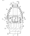
- FIG. 1 is an axial cross-sectional view of a double offset type constant velocity joint of a first embodiment
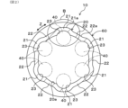
- FIG. 2 is a radial cross-sectional view of the outer ring and the boot in FIG. 1
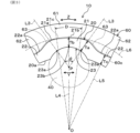
- FIG. 3 is an enlarged view of region B in FIG.
- FIG. 4 is an enlarged view of area A in FIG.
- a double offset type constant velocity joint (hereinafter simply referred to as a "constant velocity joint") 10 of embodiment 1 shown in Fig. 1 is a ball type constant velocity joint with a movable joint center.
- This constant velocity joint 10 is used, for example, in a propeller shaft for transmitting power from an internal combustion engine or an electric motor to a differential device in a vehicle.
- This constant velocity joint 10 includes, as its main components, an outer ring 20, an inner ring 30, a plurality of balls 40, a cage 50, and a boot 60.
- the right side of the figure is the opening side of the outer ring 20 (outer ring opening side), and the left side of the figure is the rear side of the outer ring 20 (outer ring rear side or opposite opening side).
- the axial direction is indicated by arrow X
- the radial direction is indicated by arrow Y
- the circumferential direction is indicated by arrow Z.
- the outer ring 20 is formed in a bottomed cylindrical shape having an opening 20b on the right side of the figure.
- a connecting shaft portion 20d is integrally formed so as to extend in the axial direction X on the outside (left side of the figure) of the bottom portion 20c of the outer ring 20.
- the connecting shaft portion 20d is connected to a power transmission shaft (not shown).
- the inner peripheral surface 20a of the outer ring 20 is formed in a straight shape in the axial direction X.
- the inner peripheral surface 20a of the outer ring 20 is provided with a plurality of outer ring ball grooves 23 extending in the axial direction X that is substantially parallel to the outer ring axis L1.
- a heat treatment coil is inserted into the cylindrical space of the outer ring 20 during the manufacturing stage of the outer ring 20 to perform heat treatment.
- the outer ring ball grooves 23 of the outer ring 20 are arranged at equal intervals in the circumferential direction Z when viewed in a radial cross section cut in the radial direction Y perpendicular to the outer ring axis L1.
- Each outer ring ball groove 23 is formed so that its radial cross section has a generally arc-shaped concave shape. Note that this embodiment illustrates an example in which the number of outer ring ball grooves 23 and balls 40 are both six.
- the outer ring 20 has a first wall portion 21, which is a portion where the outer ring ball groove 23 is formed, and a second wall portion 22, which is a portion located on both sides of the first wall portion 21 in the circumferential direction Z.
- the second wall portion 22 is located between two first wall portions 21 adjacent in the circumferential direction Z. Therefore, the cylindrical portion of the outer ring 20 is divided into the first wall portion 21 and the second wall portion 22, and these first wall portions 21 and second wall portions 22 are arranged alternately in the circumferential direction Z.
- the outer ring 20 is configured such that the outer surface 21a of the first wall portion 21 protrudes outward in the radial direction Y beyond the outer surface 22a of the second wall portion 22.
- the outer surface 21a of the first wall portion 21 includes the outermost diameter portion of the outer ring 20.
- the thickness of the outer ring 20 is set to be different at each location in the circumferential direction Z. Specifically, when the thickness of the first wall portion 21 at the contact portion 23a between the outer ring ball groove 23 and the ball 40 is Ta, the thickness of the first wall portion 21 at the groove bottom 23b of the outer ring ball groove 23 is Tb, and the thickness of the second wall portion 22 is Tc, the thicknesses Ta, Tb, and Tc are set to values that satisfy the following formula (1).
- thickness Ta is the thickness of the first wall portion 21 on the imaginary straight line L3 that passes through the ball center P of the ball 40 and the contact portion 23a.
- this thickness Ta corresponds to the thickness dimension of the contact portion 23a of the first wall portion 21 in the radial direction of the ball 40 (the radial distance from the contact portion 23a to the outer surface 21a of the first wall portion 21).
- the angle ⁇ between the two imaginary straight lines L3 is the contact angle between the two contact portions 23a.
- the thickness Tb is the thickness of the first wall portion 21 on the imaginary straight line L4 that passes through the joint center O, the ball center P, and the groove bottom 23b of the outer ring ball groove 23.
- this thickness Tb corresponds to the thickness dimension at the groove bottom 23b of the first wall portion 21 in the radial direction of the constant velocity joint 10 (the radial distance from the groove bottom 23b to the outer surface 21a of the first wall portion 21).
- the thickness Tc is the thickness of the second wall portion 22 on the imaginary straight line L5 that extends in the radial direction Y from the joint center O toward the second wall portion 22.
- the thickness Tc corresponds to the thickness dimension of the second wall portion 22 in the radial direction of the constant velocity joint 10.
- thickness Ta is set to be greater than both thickness Tb and thickness Tc. Furthermore, thickness Tc is set to be the same as thickness Tb or greater than thickness Tb.
- the contact portion 23a of the first wall portion 21 between the outer ring ball groove 23 and the ball 40 is the portion where the ball 40 directly slides and receives the load from the ball 40 directly.
- the thickness Ta of the first wall portion 21 at the contact portion 23a is set to be the largest.
- the remaining thicknesses Tb, Tc are set according to the strength required at each portion, within a range below the thickness Ta. In this case, it is possible to prevent the thicknesses Tb, Tc from becoming larger than necessary, and the outer ring 20 can be made lighter accordingly. As a result, it is possible to improve the fuel efficiency and power consumption of the vehicle in which the constant velocity joint 10 is installed.
- the inner surface of the second wall portion 22 of the outer ring 20 is the smallest diameter portion, whose inner diameter is smaller than the inner diameter of the inner surface of the first wall portion 21. Therefore, the inner surface of the second wall portion 22 is positioned closest to the heat treatment coil during the heat treatment of the outer ring 20 as described above. Therefore, the second wall portion 22 is more effective in improving its strength through heat treatment than the first wall portion 21. Taking this into consideration, the thickness Tb of the second wall portion 22 can be set smaller than the thickness Ta of the first wall portion 21, as shown in formula (1).
- thickness Ta, thickness Tb, and thickness Tc can be set to values that satisfy the following formula (2).
- thickness Ta is set to be greater than both thickness Tb and thickness Tc. Also, thickness Tc is set to be greater than thickness Tb.
- the outermost diameter of the outer ring 20 can be made smaller and the weight can be reduced by the thickness equivalent to the difference between the thickness Tc and the thickness Tb, compared to a uniform thickness specification in which the thickness of the outer ring 20 in the radial direction Y is constant and set to the thickness Tc, for example. Therefore, the outer ring 20 can be made smaller and lighter.
- the smaller size of the outer ring 20 is effective in improving the mountability of the constant velocity joint 10 on a vehicle, and the lighter weight of the outer ring 20 is effective in improving the fuel efficiency and electric power consumption of the vehicle.
- the inner ring 30 is formed in an annular shape and is disposed inside the outer ring 20.
- the outer peripheral surface 30a of the inner ring 30 is formed in a convex spherical shape.
- the inner ring 30 is connected to a power transmission shaft 32.
- the outer peripheral surface 30a of the inner ring 30 is provided with a plurality of inner ring ball grooves 31 extending in the axial direction X that is substantially parallel to the inner ring axis L2.
- the inner ring ball grooves 31 are disposed at equal intervals in the circumferential direction Z when viewed in a radial cross section cut in the radial direction Y perpendicular to the inner ring axis L2.
- the inner ring ball grooves 31 are provided in the same number as the outer ring ball grooves 23, and are disposed so that each of the inner ring ball grooves 31 and each of the outer ring ball grooves 23 face each other in the radial direction Y.
- Each inner ring ball groove 31 is formed so that the radial cross section has a generally arc-shaped concave shape.
- the plurality of balls 40 are respectively provided to be able to roll between the plurality of outer race ball grooves 23 of the outer race 20 and the plurality of inner race ball grooves 31 of the inner race 30.
- the plurality of balls 40 are arranged in the circumferential direction Z, and each ball 40 is sandwiched between the outer race ball groove 23 of the outer race 20 and the inner race ball groove 31 of the inner race 30 in the radial direction Y.
- Each ball 40 functions to transmit torque between the outer race 20 and the inner race 30.
- the cage 50 is for holding a plurality of balls 40 between the outer ring 20 and the inner ring 30.
- the cage 50 is formed in an annular shape and is disposed between the inner peripheral surface 20a of the outer ring 20 and the outer peripheral surface 30a of the inner ring 30.
- the cage 50 has a convex spherical outer surface 51 that is in sliding contact with the inner peripheral surface 20a of the outer ring 20, and a concave spherical inner surface 52 that is in sliding contact with the convex spherical outer peripheral surface 30a of the inner ring 30.
- the center C1 of the spherical outer surface 51 and the center C2 of the spherical inner surface 52 are offset from the joint center O to the opposite side of the axial direction X.
- the offset distance of the center C1 from the joint center O is the same as the offset distance of the center C2 from the joint center O.
- the center C1 of the spherical outer surface 51 and the center C2 of the spherical inner surface 52 are offset from the joint center O by an equal distance.
- the spherical outer surface 51 of the retainer 50 is formed by a portion of a sphere drawn with the center C1, which is a point offset a predetermined distance from the joint center O toward the rear of the outer ring in the axial direction X, as the center of curvature.
- the spherical inner surface 52 of the retainer 50 is formed by a portion of a sphere drawn with the center C2, which is a point offset a predetermined distance from the joint center O toward the outer ring opening in the axial direction X, as the center of curvature.
- the boot 60 is formed in a bellows tube shape that is expandable and contractible in the axial direction X and is bendable.
- the boot 60 is made of a flexible resin material or rubber material.
- One end 60a of the boot 60 in the axial direction X is fitted onto the outer peripheral surface of the opening 20b side of the outer ring 20 and is attached to the outer ring 20 by being fastened with an annular clamp 70.
- the other end 60b of the boot 60 in the axial direction X is fitted onto the axial circumference of the power transmission shaft 32 and is fastened with an annular clamp 71 to be attached to the power transmission shaft 32.
- the boot 60 serves to seal the grease contained in the inner region of the outer ring 20 so as not to leak out.
- the boot 60 has a first engagement portion 61 that engages with the outer surface 21a of the first wall portion 21 of the outer ring 20, and a second engagement portion 62 that engages with the outer surface 22a of the second wall portion 22 of the outer ring 20.
- the first engagement portions 61 and the second engagement portions 62 are arranged alternately in the circumferential direction Z.
- the second engagement portion 62 has the same outer diameter as the first engagement portion 61, but a smaller inner diameter than the first engagement portion 61.
- the inner surface 61c of the boot 60 is provided with an engagement protrusion 63 that extends annularly along the circumferential direction Z.
- the number and shape of the engagement protrusions 63 are not particularly limited, but in this embodiment, two engagement protrusions 63 are provided with a gap in the axial direction X, and each engagement protrusion 63 has a substantially triangular cross-sectional shape.
- the outermost diameter portion of the outer surface 21a of the first wall portion 21 of the outer ring 20 is an arc surface 21b concentric with the joint center O.
- This arc surface 21b is a surface along an imaginary circle L6 centered on the joint center O, and its dimension in the circumferential direction Z is indicated by the arc length D in Figure 3.
- This arc surface 21b is provided with a boot groove 21c into which the engagement protrusion 63 is fitted when the boot 60 is attached.
- the boot groove 21c is a groove portion of a fixed depth (see Figure 4).
- the outer surface 22a of the second wall portion 22 does not have a portion equivalent to the boot groove 21c.
- the arc length D of the arc surface 21b is not particularly limited, but as an example, it is preferable to set the arc length D so that the angle around the joint center O is in the range of 20° to 30°. Such a setting is effective in making it difficult for the engagement protrusion 63 of the boot 60 to come out of the boot groove 21c of the outer ring 20.
- the boot groove 21c of the first wall portion 21 is provided so as to be concentric with the joint center O, just like the arc surface 21b of the outer surface 21a. In this way, by making the boot groove 21c concentric with the joint center O, it becomes possible to easily form the boot groove 21c by turning the arc surface 21b of the first wall portion 21.
- the outer ring 20 of the constant velocity joint 10 of embodiment 1 is configured so that the thickness Ta of the first wall portion 21 at the contact portion 23a between the outer ring ball groove 23 and the ball 40, the thickness Tb of the first wall portion 21 at the groove bottom 23b of the outer ring ball groove 23, and the thickness Tc of the second wall portion 22 satisfy the above formula (1) or (2).
- the contact portion 23a between the outer ring ball groove 23 and the ball 40 is a particularly important portion in terms of strength management of the outer ring 20, as it directly receives the load from the ball 40.
- the contact portion 23a between the outer ring ball groove 23 and the ball 40 is used as a reference, the thickness Ta at this contact portion 23a is set to be the largest, and the thicknesses Tb, Tc at the remaining two portions of the outer ring 20 are set based on this thickness Ta.
- the outer ring 20 is configured such that the outermost diameter portion of the outer surface 21a of the first wall portion 21 is an arcuate surface 21b, but if necessary, the outermost diameter portion of the outer surface 21a may be a curved surface other than an arcuate surface.
- a constant velocity joint 10 that is incorporated into a vehicle's propeller shaft is exemplified, but the structure of this constant velocity joint 10 may also be applied to a joint that is incorporated into a drive shaft that is connected to the wheels of a vehicle and transmits power generated by a drive source such as an internal combustion engine or an electric motor to the wheels.
Landscapes
- Engineering & Computer Science (AREA)
- General Engineering & Computer Science (AREA)
- Mechanical Engineering (AREA)
- Rolling Contact Bearings (AREA)
- Motor Power Transmission Devices (AREA)
Priority Applications (5)
| Application Number | Priority Date | Filing Date | Title |
|---|---|---|---|
| US19/474,025 US20260235167A1 (en) | 2023-05-02 | 2023-05-02 | Double offset constant velocity joint |
| PCT/JP2023/017176 WO2024228263A1 (ja) | 2023-05-02 | 2023-05-02 | ダブルオフセット型等速ジョイント |
| CN202380097192.XA CN121039411A (zh) | 2023-05-02 | 2023-05-02 | 双偏置型等速万向节 |
| DE112023006252.8T DE112023006252T5 (de) | 2023-05-02 | 2023-05-02 | Doppelt versetztes gleichlaufgelenk |
| JP2025518085A JPWO2024228263A1 (cg-RX-API-DMAC7.html) | 2023-05-02 | 2023-05-02 |
Applications Claiming Priority (1)
| Application Number | Priority Date | Filing Date | Title |
|---|---|---|---|
| PCT/JP2023/017176 WO2024228263A1 (ja) | 2023-05-02 | 2023-05-02 | ダブルオフセット型等速ジョイント |
Publications (1)
| Publication Number | Publication Date |
|---|---|
| WO2024228263A1 true WO2024228263A1 (ja) | 2024-11-07 |
Family
ID=93332907
Family Applications (1)
| Application Number | Title | Priority Date | Filing Date |
|---|---|---|---|
| PCT/JP2023/017176 Ceased WO2024228263A1 (ja) | 2023-05-02 | 2023-05-02 | ダブルオフセット型等速ジョイント |
Country Status (5)
| Country | Link |
|---|---|
| US (1) | US20260235167A1 (cg-RX-API-DMAC7.html) |
| JP (1) | JPWO2024228263A1 (cg-RX-API-DMAC7.html) |
| CN (1) | CN121039411A (cg-RX-API-DMAC7.html) |
| DE (1) | DE112023006252T5 (cg-RX-API-DMAC7.html) |
| WO (1) | WO2024228263A1 (cg-RX-API-DMAC7.html) |
Citations (4)
| Publication number | Priority date | Publication date | Assignee | Title |
|---|---|---|---|---|
| JPH0587335U (ja) * | 1992-04-30 | 1993-11-26 | エヌティエヌ株式会社 | ステアリング用等速自在継手 |
| JP2007285443A (ja) * | 2006-04-18 | 2007-11-01 | Ntn Corp | 固定式等速自在継手の外側継手部材 |
| JP2011231792A (ja) * | 2010-04-23 | 2011-11-17 | Ntn Corp | 摺動式等速自在継手およびその外側継手部材のしごき加工方法 |
| JP2022059271A (ja) * | 2020-10-01 | 2022-04-13 | 株式会社ジェイテクト | 等速自在継手 |
Family Cites Families (1)
| Publication number | Priority date | Publication date | Assignee | Title |
|---|---|---|---|---|
| ATE427215T1 (de) | 2006-12-14 | 2009-04-15 | Bobst Sa | Kupplungsvorrichtung fur den antrieb eines zylinders einer druckvorrichtung |
-
2023
- 2023-05-02 WO PCT/JP2023/017176 patent/WO2024228263A1/ja not_active Ceased
- 2023-05-02 JP JP2025518085A patent/JPWO2024228263A1/ja active Pending
- 2023-05-02 CN CN202380097192.XA patent/CN121039411A/zh active Pending
- 2023-05-02 US US19/474,025 patent/US20260235167A1/en active Pending
- 2023-05-02 DE DE112023006252.8T patent/DE112023006252T5/de active Pending
Patent Citations (4)
| Publication number | Priority date | Publication date | Assignee | Title |
|---|---|---|---|---|
| JPH0587335U (ja) * | 1992-04-30 | 1993-11-26 | エヌティエヌ株式会社 | ステアリング用等速自在継手 |
| JP2007285443A (ja) * | 2006-04-18 | 2007-11-01 | Ntn Corp | 固定式等速自在継手の外側継手部材 |
| JP2011231792A (ja) * | 2010-04-23 | 2011-11-17 | Ntn Corp | 摺動式等速自在継手およびその外側継手部材のしごき加工方法 |
| JP2022059271A (ja) * | 2020-10-01 | 2022-04-13 | 株式会社ジェイテクト | 等速自在継手 |
Also Published As
| Publication number | Publication date |
|---|---|
| DE112023006252T5 (de) | 2026-04-16 |
| CN121039411A (zh) | 2025-11-28 |
| JPWO2024228263A1 (cg-RX-API-DMAC7.html) | 2024-11-07 |
| US20260235167A1 (en) | 2026-08-13 |
Similar Documents
| Publication | Publication Date | Title |
|---|---|---|
| US8328650B2 (en) | Constant velocity universal joint | |
| WO2012165395A1 (ja) | 摩擦伝動式波動変速機 | |
| JP2019515201A (ja) | 等速ジョイント用ブーツアセンブリ | |
| WO2019208277A1 (ja) | プロペラシャフト用摺動式等速自在継手 | |
| CN105358852B (zh) | 车轮用轴承装置 | |
| US11306805B2 (en) | Contoured differential gear washer with defined fluid flow path | |
| CN121039411A (zh) | 双偏置型等速万向节 | |
| CN219242550U (zh) | 曲轴总成和发动机 | |
| JP5834968B2 (ja) | 十字軸式自在継手 | |
| JP5625534B2 (ja) | 摺動式トリポード型等速ジョイント | |
| JP2009121667A (ja) | 摺動式等速自在継手 | |
| JP2008082393A (ja) | 自動車用駆動軸 | |
| JP2008208858A (ja) | トリポート型等速ジョイント | |
| US12537415B2 (en) | Rotary electric machine | |
| US12535108B2 (en) | Constant velocity universal joint and manufacturing method of constant velocity universal joint | |
| US12379000B2 (en) | Constant velocity joint with staking features | |
| JP2010025207A (ja) | 等速自在継手 | |
| JP2024175821A (ja) | 車輪用軸受装置 | |
| JP2019190548A (ja) | プロペラシャフト用摺動式等速自在継手 | |
| JP2026059474A (ja) | 等速自在継手 | |
| JP2018048669A (ja) | 摺動式等速自在継手 | |
| JPH0744969U (ja) | プロペラシャフト用等速ジョイントのブーツ | |
| JP2024136807A (ja) | 等速自在継手用ブーツの取付構造 | |
| WO2024228235A1 (ja) | 駆動力伝達装置 | |
| JP2023167170A (ja) | 動力伝達軸、及びこれを備えている車両 |
Legal Events
| Date | Code | Title | Description |
|---|---|---|---|
| 121 | Ep: the epo has been informed by wipo that ep was designated in this application |
Ref document number: 23935630 Country of ref document: EP Kind code of ref document: A1 |
|
| WWE | Wipo information: entry into national phase |
Ref document number: 2025518085 Country of ref document: JP |
|
| WWE | Wipo information: entry into national phase |
Ref document number: 112023006252 Country of ref document: DE |
|
| WWP | Wipo information: published in national office |
Ref document number: 112023006252 Country of ref document: DE |
|
| 122 | Ep: pct application non-entry in european phase |
Ref document number: 23935630 Country of ref document: EP Kind code of ref document: A1 |