WO2024225453A1 - ショベル、遠隔操作システム、及び、制御方法 - Google Patents
ショベル、遠隔操作システム、及び、制御方法 Download PDFInfo
- Publication number
- WO2024225453A1 WO2024225453A1 PCT/JP2024/016508 JP2024016508W WO2024225453A1 WO 2024225453 A1 WO2024225453 A1 WO 2024225453A1 JP 2024016508 W JP2024016508 W JP 2024016508W WO 2024225453 A1 WO2024225453 A1 WO 2024225453A1
- Authority
- WO
- WIPO (PCT)
- Prior art keywords
- boom
- arm
- bucket
- end attachment
- construction surface
- Prior art date
- Legal status (The legal status is an assumption and is not a legal conclusion. Google has not performed a legal analysis and makes no representation as to the accuracy of the status listed.)
- Ceased
Links
Images




Classifications
-
- E—FIXED CONSTRUCTIONS
- E02—HYDRAULIC ENGINEERING; FOUNDATIONS; SOIL SHIFTING
- E02F—DREDGING; SOIL-SHIFTING
- E02F9/00—Component parts of dredgers or soil-shifting machines, not restricted to one of the kinds covered by groups E02F3/00 - E02F7/00
- E02F9/20—Drives; Control devices
- E02F9/2025—Particular purposes of control systems not otherwise provided for
- E02F9/205—Remotely operated machines, e.g. unmanned vehicles
-
- E—FIXED CONSTRUCTIONS
- E02—HYDRAULIC ENGINEERING; FOUNDATIONS; SOIL SHIFTING
- E02F—DREDGING; SOIL-SHIFTING
- E02F3/00—Dredgers; Soil-shifting machines
- E02F3/04—Dredgers; Soil-shifting machines mechanically-driven
- E02F3/28—Dredgers; Soil-shifting machines mechanically-driven with digging tools mounted on a dipper- or bucket-arm, i.e. there is either one arm or a pair of arms, e.g. dippers, buckets
- E02F3/36—Component parts
- E02F3/42—Drives for dippers, buckets, dipper-arms or bucket-arms
- E02F3/43—Control of dipper or bucket position; Control of sequence of drive operations
-
- E—FIXED CONSTRUCTIONS
- E02—HYDRAULIC ENGINEERING; FOUNDATIONS; SOIL SHIFTING
- E02F—DREDGING; SOIL-SHIFTING
- E02F3/00—Dredgers; Soil-shifting machines
- E02F3/04—Dredgers; Soil-shifting machines mechanically-driven
- E02F3/28—Dredgers; Soil-shifting machines mechanically-driven with digging tools mounted on a dipper- or bucket-arm, i.e. there is either one arm or a pair of arms, e.g. dippers, buckets
- E02F3/36—Component parts
- E02F3/42—Drives for dippers, buckets, dipper-arms or bucket-arms
- E02F3/43—Control of dipper or bucket position; Control of sequence of drive operations
- E02F3/435—Control of dipper or bucket position; Control of sequence of drive operations for dipper-arms, backhoes or the like
-
- E—FIXED CONSTRUCTIONS
- E02—HYDRAULIC ENGINEERING; FOUNDATIONS; SOIL SHIFTING
- E02F—DREDGING; SOIL-SHIFTING
- E02F3/00—Dredgers; Soil-shifting machines
- E02F3/04—Dredgers; Soil-shifting machines mechanically-driven
- E02F3/28—Dredgers; Soil-shifting machines mechanically-driven with digging tools mounted on a dipper- or bucket-arm, i.e. there is either one arm or a pair of arms, e.g. dippers, buckets
- E02F3/36—Component parts
- E02F3/42—Drives for dippers, buckets, dipper-arms or bucket-arms
- E02F3/43—Control of dipper or bucket position; Control of sequence of drive operations
- E02F3/435—Control of dipper or bucket position; Control of sequence of drive operations for dipper-arms, backhoes or the like
- E02F3/437—Control of dipper or bucket position; Control of sequence of drive operations for dipper-arms, backhoes or the like providing automatic sequences of movements, e.g. linear excavation, keeping dipper angle constant
-
- E—FIXED CONSTRUCTIONS
- E02—HYDRAULIC ENGINEERING; FOUNDATIONS; SOIL SHIFTING
- E02F—DREDGING; SOIL-SHIFTING
- E02F3/00—Dredgers; Soil-shifting machines
- E02F3/04—Dredgers; Soil-shifting machines mechanically-driven
- E02F3/28—Dredgers; Soil-shifting machines mechanically-driven with digging tools mounted on a dipper- or bucket-arm, i.e. there is either one arm or a pair of arms, e.g. dippers, buckets
- E02F3/36—Component parts
- E02F3/42—Drives for dippers, buckets, dipper-arms or bucket-arms
- E02F3/43—Control of dipper or bucket position; Control of sequence of drive operations
- E02F3/435—Control of dipper or bucket position; Control of sequence of drive operations for dipper-arms, backhoes or the like
- E02F3/439—Automatic repositioning of the implement, e.g. automatic dumping, auto-return
-
- E—FIXED CONSTRUCTIONS
- E02—HYDRAULIC ENGINEERING; FOUNDATIONS; SOIL SHIFTING
- E02F—DREDGING; SOIL-SHIFTING
- E02F9/00—Component parts of dredgers or soil-shifting machines, not restricted to one of the kinds covered by groups E02F3/00 - E02F7/00
- E02F9/08—Superstructures; Supports for superstructures
- E02F9/10—Supports for movable superstructures mounted on travelling or walking gears or on other superstructures
- E02F9/12—Slewing or traversing gears
- E02F9/121—Turntables, i.e. structure rotatable about 360°
- E02F9/123—Drives or control devices specially adapted therefor
-
- E—FIXED CONSTRUCTIONS
- E02—HYDRAULIC ENGINEERING; FOUNDATIONS; SOIL SHIFTING
- E02F—DREDGING; SOIL-SHIFTING
- E02F9/00—Component parts of dredgers or soil-shifting machines, not restricted to one of the kinds covered by groups E02F3/00 - E02F7/00
- E02F9/20—Drives; Control devices
-
- E—FIXED CONSTRUCTIONS
- E02—HYDRAULIC ENGINEERING; FOUNDATIONS; SOIL SHIFTING
- E02F—DREDGING; SOIL-SHIFTING
- E02F9/00—Component parts of dredgers or soil-shifting machines, not restricted to one of the kinds covered by groups E02F3/00 - E02F7/00
- E02F9/20—Drives; Control devices
- E02F9/2025—Particular purposes of control systems not otherwise provided for
- E02F9/2033—Limiting the movement of frames or implements, e.g. to avoid collision between implements and the cabin
-
- E—FIXED CONSTRUCTIONS
- E02—HYDRAULIC ENGINEERING; FOUNDATIONS; SOIL SHIFTING
- E02F—DREDGING; SOIL-SHIFTING
- E02F9/00—Component parts of dredgers or soil-shifting machines, not restricted to one of the kinds covered by groups E02F3/00 - E02F7/00
- E02F9/20—Drives; Control devices
- E02F9/22—Hydraulic or pneumatic drives
- E02F9/2278—Hydraulic circuits
- E02F9/2285—Pilot-operated systems
-
- E—FIXED CONSTRUCTIONS
- E02—HYDRAULIC ENGINEERING; FOUNDATIONS; SOIL SHIFTING
- E02F—DREDGING; SOIL-SHIFTING
- E02F9/00—Component parts of dredgers or soil-shifting machines, not restricted to one of the kinds covered by groups E02F3/00 - E02F7/00
- E02F9/26—Indicating devices
-
- E—FIXED CONSTRUCTIONS
- E02—HYDRAULIC ENGINEERING; FOUNDATIONS; SOIL SHIFTING
- E02F—DREDGING; SOIL-SHIFTING
- E02F9/00—Component parts of dredgers or soil-shifting machines, not restricted to one of the kinds covered by groups E02F3/00 - E02F7/00
- E02F9/26—Indicating devices
- E02F9/261—Surveying the work-site to be treated
- E02F9/262—Surveying the work-site to be treated with follow-up actions to control the work tool, e.g. controller
-
- E—FIXED CONSTRUCTIONS
- E02—HYDRAULIC ENGINEERING; FOUNDATIONS; SOIL SHIFTING
- E02F—DREDGING; SOIL-SHIFTING
- E02F9/00—Component parts of dredgers or soil-shifting machines, not restricted to one of the kinds covered by groups E02F3/00 - E02F7/00
- E02F9/26—Indicating devices
- E02F9/264—Sensors and their calibration for indicating the position of the work tool
- E02F9/265—Sensors and their calibration for indicating the position of the work tool with follow-up actions (e.g. control signals sent to actuate the work tool)
Definitions
- the present invention relates to an excavator, a remote control system, and a control method.
- One aspect of the present invention provides a technology that can improve work efficiency by moving an end attachment by rotating the shovel while the end attachment is in contact with a slope, allowing work to be performed according to the operator's needs.
- a shovel comprises a lower running body, an upper rotating body mounted on the lower running body so as to be freely rotatable, a boom attached to the upper rotating body, an arm attached to the boom, an end attachment attached to the arm, and a control device that controls any one or more of the boom, the arm, and the end attachment so that, when the upper rotating body is rotated in accordance with the operation of an operator, after a working part of the end attachment comes into contact with a construction surface on which the end attachment is to be worked, the working part follows the construction surface.
- slope shaping can be performed by rotating the machine, improving work efficiency.
- FIG. 1 is a side view of a shovel according to a first embodiment.
- FIG. 2 is a diagram illustrating an example of a configuration of a shovel according to the first embodiment.
- FIG. 3 is a diagram illustrating an example of a configuration of a hydraulic system of the excavator according to the first embodiment.
- FIG. 4 is a diagram illustrating a hydraulic system portion related to the operation of the swing hydraulic motor according to the first embodiment.
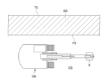
- FIG. 5A is an explanatory diagram showing a slope shaping operation based on a turning operation by a shovel according to the first embodiment.
- FIG. 5B is an explanatory diagram showing a slope shaping operation based on a turning operation by the shovel according to the first embodiment.
- FIG. 5A is an explanatory diagram showing a slope shaping operation based on a turning operation by a shovel according to the first embodiment.
- FIG. 5B is an explanatory diagram showing a slope shaping operation based on a turning operation by the shovel according to the first embodiment
- FIG. 5C is an explanatory diagram showing a slope shaping operation based on a turning operation by the shovel according to the first embodiment.
- FIG. 6 is a diagram illustrating a slope shaping by the working parts of the bucket according to the first embodiment.
- FIG. 7 is a flowchart showing the procedure for processing a slope shaping operation by the machine guidance unit according to the first embodiment when the upper rotating body 3 performs a rotating operation.
- FIG. 8 is a diagram illustrating the operation control of the automatic control unit according to the second modification.
- FIG. 9 is a schematic diagram illustrating an example of a remote control system according to the second embodiment.
- a shovel is used as an example of a work machine, but the present invention is not limited to a shovel.
- the present invention may be applied to construction machines, standard machines, application machines, forestry machines, or transport machines based on hydraulic shovels.
- Fig. 1 is a side view of the shovel 100 as a work machine according to this embodiment.
- the excavator 100 includes a lower running body 1, an upper rotating body 3 mounted on the lower running body 1 so as to be freely rotatable via a rotating mechanism 2, a boom 4, an arm 5, and a bucket 6 constituting an attachment (working machine), and a cabin 10.
- the lower traveling body 1 allows the excavator 100 to travel by hydraulically driving a pair of left and right crawlers by traveling hydraulic motors 1L, 1R (see FIG. 2 described later).
- the pair of traveling hydraulic motors 1L, 1R (an example of a traveling motor) drive the lower traveling body 1 (crawlers) as the driven part.
- the upper rotating body 3 is driven by a rotation hydraulic motor 2A (see FIG. 2 described later) to rotate relative to the lower traveling body 1.
- the rotation hydraulic motor 2A is a rotation drive part that drives the upper rotating body 3 as a driven part, and can change the orientation of the upper rotating body 3.
- the upper rotating body 3 may be electrically driven by an electric motor (hereinafter, "swivel electric motor”) instead of the swivel hydraulic motor 2A.
- swivel electric motor like the swivel hydraulic motor 2A, is a swivel drive part that drives the upper rotating body 3 as a non-driven part, and can change the orientation of the upper rotating body 3.
- the boom 4 is pivotally attached to the front center of the upper rotating body 3 so that it can be raised and lowered, and an arm 5 is pivotally attached to the tip of the boom 4 so that it can rotate up and down, and a bucket 6 as an end attachment is pivotally attached to the tip of the arm 5 so that it can rotate up and down.
- the boom 4, arm 5, and bucket 6 are hydraulically driven by a boom cylinder 7, arm cylinder 8, and bucket cylinder 9, which serve as hydraulic actuators, respectively.
- the bucket 6 is an example of an end attachment (work tool), and instead of the bucket 6, another end attachment capable of driving soil, such as a slope bucket, may be attached to the tip of the arm 5 depending on the type of work being performed.
- another end attachment capable of driving soil such as a slope bucket
- the cabin 10 is the driver's cab in which the operator sits, and is mounted on the front left side of the upper rotating body 3.
- FIG. 2 is a diagram showing an example of the configuration of the shovel 100 according to this embodiment.
- the drive system of the excavator 100 includes the engine 11, regulator 13, main pump 14, and control valve 17.
- the hydraulic drive system of the excavator 100 according to this embodiment includes hydraulic actuators such as traveling hydraulic motors 1L, 1R, swing hydraulic motor 2A, boom cylinder 7, arm cylinder 8, and bucket cylinder 9 that hydraulically drive the lower traveling body 1, upper rotating body 3, boom 4, arm 5, and bucket 6, respectively.
- the engine 11 is the main power source in the hydraulic drive system, and is mounted, for example, at the rear of the upper rotating body 3. Specifically, the engine 11 rotates at a constant speed at a preset target speed under direct or indirect control by a controller 30 (described later), and drives the main pump 14 and pilot pump 15.
- the engine 11 is, for example, a diesel engine that uses diesel as fuel.
- the regulator 13 controls the discharge volume of the main pump 14. For example, the regulator 13 adjusts the angle (tilt angle) of the swash plate of the main pump 14 in response to a control command from the controller 30.
- the regulator 13 includes, for example, regulators 13L and 13R, as described below.
- the main pump 14 is mounted on the rear of the upper rotating body 3, for example, like the engine 11, and supplies hydraulic oil to the control valve 17 through a high-pressure hydraulic line.
- the main pump 14 is driven by the engine 11 as described above.
- the main pump 14 is, for example, a variable displacement hydraulic pump, and as described above, under the control of the controller 30, the tilt angle of the swash plate is adjusted by the regulator 13 to adjust the stroke length of the piston and control the discharge flow rate (discharge pressure).
- the main pump 14 includes, for example, main pumps 14L, 14R, as described below.
- the control valve 17 is a hydraulic control device that controls the hydraulic system in the excavator 100.
- the control valve 17 includes control valves 171 to 176.
- the control valve 175 includes control valve 175L and control valve 175R
- the control valve 176 includes control valve 176L and control valve 176R.
- the control valve 17 is configured to selectively supply hydraulic oil discharged by the main pump 14 to one or more hydraulic actuators through the control valves 171 to 176.
- the control valves 171 to 176 control, for example, the flow rate of hydraulic oil flowing from the main pump 14 to the hydraulic actuators, and the flow rate of hydraulic oil flowing from the hydraulic actuators to a hydraulic oil tank.
- the hydraulic actuators include a boom cylinder 7, an arm cylinder 8, a bucket cylinder 9, traveling hydraulic motors 1L and 1R, and a swing hydraulic motor 2A. More specifically, control valve 171 corresponds to left traveling hydraulic motor 1L, control valve 172 corresponds to right traveling hydraulic motor 1R, and control valve 173 corresponds to swing hydraulic motor 2A. Control valve 174 corresponds to bucket cylinder 9, control valve 175 corresponds to boom cylinder 7, and control valve 176 corresponds to arm cylinder 8. Control valve 175 includes control valves 175L and 175R, for example, as described below, and control valve 176 includes control valves 176L and 176R, for example, as described below. Details of control valves 171 to 176 will be described later.
- the pilot pump 15 is an example of a pilot pressure generating device, and is configured to be able to supply hydraulic oil to hydraulic control devices via a pilot line.
- the pilot pump 15 is a fixed displacement hydraulic pump.
- the pilot pressure generating device may be realized by the main pump 14. That is, the main pump 14 may have a function of supplying hydraulic oil to various hydraulic control devices via a pilot line, in addition to a function of supplying hydraulic oil to the control valve 17 via a hydraulic oil line. In this case, the pilot pump 15 may be omitted.
- the operating device 26 is a device that an operator uses to operate the actuator.
- the actuator includes at least one of a hydraulic actuator and an electric actuator.
- the discharge pressure sensor 28 is configured to detect the discharge pressure of the main pump 14. In this embodiment, the discharge pressure sensor 28 outputs the detected value to the controller 30.
- the discharge pressure sensor 28 includes, for example, discharge pressure sensors 28L and 28R, as described below.
- the operation sensor 29 is configured to detect the operation content of the operator using the operating device 26.
- the operation sensor 29 detects the operation direction and operation amount of the operating device 26 corresponding to each actuator, and outputs the detected value to the controller 30.
- the controller 30 controls the opening area of the proportional valve 31 according to the output of the operation sensor 29.
- the controller 30 then supplies the hydraulic oil discharged by the pilot pump 15 to the pilot port of the corresponding control valve in the control valve 17.
- the pressure of the hydraulic oil (pilot pressure) supplied to each pilot port is, in principle, a pressure according to the operation direction and operation amount of the operating device 26 corresponding to each hydraulic actuator. In this way, the operating device 26 is configured to be able to supply the hydraulic oil discharged by the pilot pump 15 to the pilot port of the corresponding control valve in the control valve 17.
- the proportional valve 31 which functions as a control valve for machine control, is disposed in a pipe connecting the pilot pump 15 and the pilot port of the control valve in the control valve 17, and is configured so that the flow path area of the pipe can be changed.
- the proportional valve 31 operates in response to a control command output by the controller 30. Therefore, the controller 30 can supply the hydraulic oil discharged by the pilot pump 15 to the pilot port of the control valve in the control valve 17 via the proportional valve 31, regardless of the operation of the operating device 26 by the operator.
- the proportional valve 31 includes, for example, proportional valves 31AL, 31AR, 31BL, 31BR, 31CL, and 31CR, as described below.
- the controller 30 can operate the hydraulic actuator corresponding to a specific operating device 26 even when no operation is being performed on that specific operating device 26.
- the control system of the excavator 100 includes a controller 30, a display device 40, an input device 42, an audio output device 43, a storage device 47, a boom angle sensor S1, an arm angle sensor S2, a bucket angle sensor S3, a machine body tilt sensor (an example of an attitude detection unit) S4, a turning state sensor S5, an imaging device S6, a positioning device PS, and a communication device T1.
- the controller 30 (an example of a control device) is provided, for example, in the cabin 10 and controls the drive of the excavator 100.
- the functions of the controller 30 may be realized by any hardware, software, or a combination thereof.
- the controller 30 is mainly composed of a microcomputer including a CPU (Central Processing Unit), ROM (Read Only Memory), RAM (Random Access Memory), a non-volatile auxiliary storage device, and various input/output interfaces.
- the controller 30 realizes various functions by, for example, executing various programs stored in the ROM or non-volatile auxiliary storage device on the CPU.
- the controller 30 sets a target rotation speed based on the operation of an operator, etc., and performs drive control to keep the engine 11 rotating at a constant speed.
- the controller 30 also outputs a control command to the regulator 13 as necessary to change the discharge rate of the main pump 14.
- the controller 30 performs control related to a machine guidance function that guides (guides) the manual operation of the shovel 100 by the operator through the operation device 26. Further, the controller 30 performs control related to a machine control function that automatically assists the manual operation of the shovel 100 by the operator through the operation device 26.
- the controller 30 includes a machine guidance unit 50 as a functional unit related to the machine guidance function and the machine control function.
- controller 30 may be realized by other controllers (control devices). That is, the functions of the controller 30 may be realized in a distributed manner by multiple controllers.
- the machine guidance function and the machine control function may be realized by a dedicated controller (control device).
- the display device 40 is provided in a location that is easily visible to an operator seated in the cabin 10, and displays various information images under the control of the controller 30.
- the display device 40 may be connected to the controller 30 via an in-vehicle communication network such as a Controller Area Network (CAN), or may be connected to the controller 30 via a one-to-one dedicated line.
- CAN Controller Area Network
- the input device 42 is provided within reach of an operator seated in the cabin 10, accepts various operational inputs by the operator, and outputs signals corresponding to the operational inputs to the controller 30.
- the input device 42 includes a touch panel mounted on the display of a display device that displays various information images, knob switches provided at the tips of the lever portions of the lever devices 26A to 26C, button switches, levers, toggles, rotary dials, etc., that are installed around the display device 40. Signals corresponding to the operations performed on the input device 42 are taken into the controller 30.
- the audio output device 43 is provided, for example, in the cabin 10, connected to the controller 30, and outputs audio under the control of the controller 30.
- the audio output device 43 is, for example, a speaker or a buzzer.
- the audio output device 43 outputs various information by audio in response to an audio output command from the controller 30.
- the storage device 47 is provided, for example, in the cabin 10, and stores various information under the control of the controller 30.
- the storage device 47 is, for example, a non-volatile storage medium such as a semiconductor memory.
- the storage device 47 may store information output by various devices during operation of the shovel 100, or may store information acquired via various devices before operation of the shovel 100 is started.
- the storage device 47 may store, for example, data relating to a target construction surface acquired via the communication device T1, etc., or set via the input device 42, etc.
- the target construction surface may be set (saved) by the operator of the shovel 100, or may be set by a construction manager, etc.
- the boom angle sensor S1 is attached to the boom 4 and detects the elevation angle of the boom 4 relative to the upper rotating body 3 (hereinafter referred to as the "boom angle"), for example, the angle formed by a straight line connecting the fulcrums at both ends of the boom 4 relative to the rotation plane of the upper rotating body 3 in a side view.
- the boom angle sensor S1 may include, for example, a rotary encoder, an acceleration sensor, a six-axis sensor, an IMU (Inertial Measurement Unit), etc.
- the boom angle sensor S1 may also include a potentiometer using a variable resistor, a cylinder stroke sensor that detects the stroke amount of a hydraulic cylinder (boom cylinder 7) corresponding to the boom angle, etc.
- the detection signal corresponding to the boom angle by the boom angle sensor S1 is taken into the controller 30.
- the arm angle sensor S2 is attached to the arm 5 and detects the rotation angle of the arm 5 relative to the boom 4 (hereinafter, "arm angle"), for example, the angle formed by a line connecting the fulcrums at both ends of the arm 5 with a line connecting the fulcrums at both ends of the boom 4 in a side view.
- a detection signal corresponding to the arm angle by the arm angle sensor S2 is input to the controller 30.
- the bucket angle sensor S3 is attached to the bucket 6 and detects the rotation angle of the bucket 6 relative to the arm 5 (hereinafter referred to as the "bucket angle"), for example, the angle formed by a line connecting the fulcrums at both ends of the arm 5 and a line connecting the fulcrum and tip (tip) of the bucket 6 in a side view.
- the detection signal corresponding to the bucket angle by the bucket angle sensor S3 is input to the controller 30.
- the machine body tilt sensor S4 detects the tilt state of the machine body (upper rotating body 3 or lower running body 1) relative to the horizontal plane.
- the machine body tilt sensor S4 is attached, for example, to the upper rotating body 3, and detects the tilt angles around two axes in the fore-aft and lateral directions (hereinafter referred to as "fore-aft tilt angle” and "lateral tilt angle") of the shovel 100 (i.e., upper rotating body 3).
- the machine body tilt sensor S4 may include, for example, a rotary encoder, an acceleration sensor, a six-axis sensor, an IMU, etc.
- the detection signal corresponding to the tilt angle (fore-aft tilt angle and lateral tilt angle) by the machine body tilt sensor S4 is input to the controller 30.
- the rotation state sensor S5 outputs detection information regarding the rotation state of the upper rotating body 3.
- the rotation state sensor S5 detects, for example, the rotation angular velocity and rotation angle of the upper rotating body 3.
- the rotation state sensor S5 may include, for example, a gyro sensor, a resolver, a rotary encoder, etc.
- the detection signal corresponding to the rotation angle and rotation angular velocity of the upper rotating body 3 by the rotation state sensor S5 is input to the controller 30.
- the imaging device S6 which serves as a spatial recognition device, captures images of the periphery of the shovel 100.
- the imaging device S6 includes a camera S6F that captures an image in front of the shovel 100, a camera S6L that captures an image to the left of the shovel 100, a camera S6R that captures an image to the right of the shovel 100, and a camera S6B that captures an image behind the shovel 100.
- Camera S6F is attached, for example, to the ceiling of cabin 10, i.e., inside cabin 10. Camera S6F may also be attached to the outside of cabin 10, such as the roof of cabin 10 or the side of boom 4. Camera S6L is attached to the left end of the top surface of upper rotating body 3, camera S6R is attached to the right end of the top surface of upper rotating body 3, and camera S6B is attached to the rear end of the top surface of upper rotating body 3.
- the imaging device S6 (cameras S6F, S6B, S6L, and S6R) is, for example, a monocular wide-angle camera with a very wide angle of view.
- the imaging device S6 may also be a stereo camera or a distance imaging camera.
- the image captured by the imaging device S6 is input to the controller 30 via the display device 40.
- the imaging device S6 as a spatial recognition device may function as an object detection device.
- the imaging device S6 may detect objects present around the shovel 100.
- the objects to be detected may include, for example, people, animals, vehicles, construction machinery, buildings, holes, etc.
- the imaging device S6 may also calculate the distance from the imaging device S6 or the shovel 100 to the recognized object.
- the imaging device S6 as an object detection device may include, for example, a stereo camera, a distance image sensor, etc.
- the spatial recognition device is, for example, a monocular camera having an imaging element such as a CCD or CMOS, and outputs the captured image to the display device 40.
- the spatial recognition device may also be configured to calculate the distance from the spatial recognition device or the shovel 100 to the recognized object.
- the spatial recognition device In addition to the imaging device S6, other object detection devices such as an ultrasonic sensor, a millimeter wave radar, a LIDAR, an infrared sensor, etc. may be provided as the spatial recognition device.
- an ultrasonic sensor a millimeter wave radar, a LIDAR, an infrared sensor, etc.
- a millimeter wave radar, ultrasonic sensor, laser radar, or the like as a spatial recognition device, multiple signals (laser light, etc.) can be emitted to an object, and the reflected signals can be received to detect the distance and direction of the object from the reflected signals.
- the imaging device S6 may also be directly connected to the controller 30 so as to be able to communicate with it.
- the boom cylinder 7 is equipped with a boom rod pressure sensor S7R and a boom bottom pressure sensor S7B.
- the arm cylinder 8 is equipped with an arm rod pressure sensor S8R and an arm bottom pressure sensor S8B.
- the bucket cylinder 9 is equipped with a bucket rod pressure sensor S9R and a bucket bottom pressure sensor S9B.
- the boom rod pressure sensor S7R, the boom bottom pressure sensor S7B, the arm rod pressure sensor S8R, the arm bottom pressure sensor S8B, the bucket rod pressure sensor S9R and the bucket bottom pressure sensor S9B are collectively referred to as the "cylinder pressure sensors.”
- the boom rod pressure sensor S7R detects the pressure in the rod side oil chamber of the boom cylinder 7 (hereafter referred to as the "boom rod pressure”), and the boom bottom pressure sensor S7B detects the pressure in the bottom side oil chamber of the boom cylinder 7 (hereafter referred to as the "boom bottom pressure”).
- the arm rod pressure sensor S8R detects the pressure in the rod side oil chamber of the arm cylinder 8 (hereafter referred to as the "arm rod pressure”), and the arm bottom pressure sensor S8B detects the pressure in the bottom side oil chamber of the arm cylinder 8 (hereafter referred to as the "arm bottom pressure").
- the bucket rod pressure sensor S9R detects the pressure in the rod side oil chamber of the bucket cylinder 9 (hereafter referred to as the "bucket rod pressure")
- the bucket bottom pressure sensor S9B detects the pressure in the bottom side oil chamber of the bucket cylinder 9 (hereafter referred to as the “bucket bottom pressure”).
- the positioning device PS measures the position and orientation of the upper rotating body 3.
- the positioning device PS is, for example, a Global Navigation Satellite System (GNSS) compass, which detects the position and orientation of the upper rotating body 3, and a detection signal corresponding to the position and orientation of the upper rotating body 3 is input to the controller 30.
- GNSS Global Navigation Satellite System
- the function of the positioning device PS to detect the orientation of the upper rotating body 3 may be substituted by a direction sensor attached to the upper rotating body 3.
- the communication device T1 communicates with external devices through a predetermined network including a mobile communication network with a base station as an end, a satellite communication network, the Internet, etc.
- the communication device T1 is, for example, a mobile communication module compatible with mobile communication standards such as LTE (Long Term Evolution), 4G (4th Generation), and 5G (5th Generation), or a satellite communication module for connecting to a satellite communication network.
- FIG. 3 is a diagram showing an example of the configuration of a hydraulic system of the excavator 100 according to this embodiment.
- the hydraulic system realized by this hydraulic circuit circulates hydraulic oil from each of the main pumps 14L, 14R driven by the engine 11 through the center bypass oil passages C1L, C1R and the parallel oil passages C2L, C2R to the hydraulic oil tank.
- the center bypass oil passage C1L starts at the main pump 14L, passes through the control valves 171, 173, 175L, and 176L arranged in the control valve 17, and reaches the hydraulic oil tank.
- the center bypass oil passage C1R starts at the main pump 14R, passes through the control valves 172, 174, 175R, and 176R arranged in the control valve 17, and reaches the hydraulic oil tank.
- the control valve 171 is a spool valve that supplies hydraulic oil discharged from the main pump 14L to the travel hydraulic motor 1L and discharges hydraulic oil discharged by the travel hydraulic motor 1L into the hydraulic oil tank.
- the control valve 172 is a spool valve that supplies hydraulic oil discharged from the main pump 14R to the traveling hydraulic motor 1R and discharges hydraulic oil discharged by the traveling hydraulic motor 1R to the hydraulic oil tank.
- the control valve 173 is a spool valve that supplies hydraulic oil discharged from the main pump 14L to the swing hydraulic motor 2A and discharges hydraulic oil discharged by the swing hydraulic motor 2A into the hydraulic oil tank.
- the control valve 174 is a spool valve that supplies hydraulic oil discharged from the main pump 14R to the bucket cylinder 9 and also discharges the hydraulic oil in the bucket cylinder 9 to the hydraulic oil tank.
- the control valves 175L and 175R are spool valves that supply hydraulic oil discharged from the main pumps 14L and 14R to the boom cylinder 7, and discharge the hydraulic oil in the boom cylinder 7 to the hydraulic oil tank.
- the control valves 176L, 176R supply hydraulic oil discharged by the main pumps 14L, 14R to the arm cylinder 8, and also discharge the hydraulic oil in the arm cylinder 8 to the hydraulic oil tank.
- Control valves 171, 172, 173, 174, 175L, 175R, 176L, and 176R each adjust the flow rate of hydraulic oil supplied to or discharged from the hydraulic actuator and switch the flow direction according to the pilot pressure acting on the pilot port.
- the parallel oil passage C2L supplies hydraulic oil of the main pump 14L to the control valves 171, 173, 175L, and 176L in parallel with the center bypass oil passage C1L.
- the parallel oil passage C2L branches off from the center bypass oil passage C1L upstream of the control valve 171, and is configured to be able to supply hydraulic oil of the main pump 14L in parallel to each of the control valves 171, 173, 175L, and 176R. This allows the parallel oil passage C2L to supply hydraulic oil to a more downstream control valve when the flow of hydraulic oil through the center bypass oil passage C1L is restricted or blocked by any of the control valves 171, 173, and 175L.
- the parallel oil passage C2R supplies hydraulic oil of the main pump 14R to the control valves 172, 174, 175R, and 176R in parallel with the center bypass oil passage C1R.
- the parallel oil passage C2R branches off from the center bypass oil passage C1R upstream of the control valve 172, and is configured to be able to supply hydraulic oil of the main pump 14R in parallel to each of the control valves 172, 174, 175R, and 176R.
- the parallel oil passage C2R can supply hydraulic oil to a more downstream control valve when the flow of hydraulic oil through the center bypass oil passage C1R is restricted or blocked by any of the control valves 172, 174, and 175R.
- the regulators 13L and 13R adjust the discharge volume of the main pumps 14L and 14R by adjusting the tilt angle of the swash plates of the main pumps 14L and 14R under the control of the controller 30.
- the discharge pressure sensor 28L detects the discharge pressure of the main pump 14L, and a detection signal corresponding to the detected discharge pressure is input to the controller 30. The same is true for the discharge pressure sensor 28R. This allows the controller 30 to control the regulators 13L, 13R according to the discharge pressures of the main pumps 14L, 14R.
- Negative control throttles (hereinafter “negative control throttles”) 18L, 18R are provided in the center bypass oil passages C1L, C1R between the hydraulic oil tank and the most downstream control valves 176L, 176R, respectively.
- negative control throttles As a result, the flow of hydraulic oil discharged by the main pumps 14L, 14R is restricted by the negative control throttles 18L, 18R.
- the negative control throttles 18L, 18R then generate a control pressure (hereinafter “negative control pressure") for controlling the regulators 13L, 13R.
- the negative control pressure sensors 19L and 19R detect the negative control pressure, and the detection signal corresponding to the detected negative control pressure is input to the controller 30.
- the controller 30 may control the regulators 13L, 13R according to the discharge pressure of the main pumps 14L, 14R detected by the discharge pressure sensors 28L, 28R to adjust the discharge volume of the main pumps 14L, 14R.
- the controller 30 may control the regulator 13L according to an increase in the discharge pressure of the main pump 14L, and reduce the discharge volume by adjusting the swash plate tilt angle of the main pump 14L.
- the controller 30 may also adjust the discharge volume of the main pumps 14L, 14R by controlling the regulators 13L, 13R according to the negative control pressure detected by the negative control pressure sensors 19L, 19R. For example, the controller 30 decreases the discharge volume of the main pumps 14L, 14R as the negative control pressure increases, and increases the discharge volume of the main pumps 14L, 14R as the negative control pressure decreases.
- the controller 30 reduces the discharge rate of the main pumps 14L, 14R to the minimum allowable discharge rate, suppressing the pressure loss (pumping loss) that occurs when the discharged hydraulic oil passes through the center bypass oil passages C1L, C1R.
- the hydraulic oil discharged from the main pumps 14L, 14R flows into the hydraulic actuator to be operated via the control valve corresponding to the hydraulic actuator to be operated.
- the flow of hydraulic oil discharged from the main pumps 14L, 14R reduces or eliminates the amount of hydraulic oil reaching the negative control throttles 18L, 18R, lowering the negative control pressure generated upstream of the negative control throttles 18L, 18R.
- the controller 30 increases the discharge amount of the main pumps 14L, 14R, circulates sufficient hydraulic oil to the hydraulic actuator to be operated, and can reliably drive the hydraulic actuator to be operated.
- the operating device 26 includes a left operating lever 26L, a right operating lever 26R, and a driving lever 26D.
- the driving lever 26D includes a left driving lever 26DL and a right driving lever 26DR.
- the left operating lever 26L is used for rotation operations and operation of the arm 5.
- the hydraulic oil discharged by the pilot pump 15 is used to introduce a control pressure according to the amount of lever operation into the pilot port of the control valve 176.
- the hydraulic oil discharged by the pilot pump 15 is used to introduce a control pressure according to the amount of lever operation into the pilot port of the control valve 173.
- the left operating lever 26L when the left operating lever 26L is operated in the arm closing direction, it introduces hydraulic oil to the right pilot port of the control valve 176L and also introduces hydraulic oil to the left pilot port of the control valve 176R.
- the left operating lever 26L When the left operating lever 26L is operated in the arm opening direction, it introduces hydraulic oil to the left pilot port of the control valve 176L and also introduces hydraulic oil to the right pilot port of the control valve 176R.
- the left operating lever 26L When the left operating lever 26L is operated in the left turning direction, it introduces hydraulic oil to the left pilot port of the control valve 173, and when operated in the right turning direction, it introduces hydraulic oil to the right pilot port of the control valve 173.
- the right operating lever 26R is used to operate the boom 4 and the bucket 6.
- the right operating lever 26R uses the hydraulic oil discharged by the pilot pump 15 to introduce a control pressure according to the amount of lever operation into the pilot port of the control valve 175.
- the right operating lever 26R uses the hydraulic oil discharged by the pilot pump 15 to introduce a control pressure according to the amount of lever operation into the pilot port of the control valve 174.
- the right operating lever 26R when the right operating lever 26R is operated in the boom lowering direction, it introduces hydraulic oil to the left pilot port of the control valve 175R.
- the right operating lever 26R When the right operating lever 26R is operated in the boom raising direction, it introduces hydraulic oil to the right pilot port of the control valve 175L and also introduces hydraulic oil to the left pilot port of the control valve 175R.
- the right operating lever 26R When the right operating lever 26R is operated in the bucket closing direction, it introduces hydraulic oil to the right pilot port of the control valve 174, and when operated in the bucket opening direction, it introduces hydraulic oil to the left pilot port of the control valve 174.
- the left operating lever 26L operated in the left-right direction may be referred to as the "swing operating lever,” and the left operating lever 26L operated in the front-rear direction may be referred to as the “arm operating lever.”
- the right operating lever 26R operated in the left-right direction may be referred to as the “bucket operating lever,” and the right operating lever 26R operated in the front-rear direction may be referred to as the "boom operating lever.”
- the left travel lever 26DL is used to operate the left crawler 1CL. It may be configured to be linked to the left travel pedal. When the left travel lever 26DL is operated in the forward/backward direction, it uses the hydraulic oil discharged by the pilot pump 15 to introduce a control pressure corresponding to the lever operation amount to the pilot port of the control valve 171.
- the right travel lever 26DR is used to operate the right crawler 1CR. It may be configured to be linked to the right travel pedal. When the right travel lever 26DR is operated in the forward/backward direction, it uses the hydraulic oil discharged by the pilot pump 15 to introduce a control pressure corresponding to the lever operation amount to the pilot port of the control valve 172.
- the operation sensor 29 is configured to detect the operation of the operation device 26 by the operator.
- the operation sensor 29 detects the operation direction and operation amount of the operation device 26 corresponding to each actuator, and outputs the detected value to the controller 30.
- the operation sensor 29 includes operation sensors 29LA, 29LB, 29RA, 29RB, 29DL, and 29DR.
- the operation sensor 29LA detects the content of the operation of the left operating lever 26L in the forward/rearward direction by the operator, and outputs the detected value to the controller 30.
- the content of the operation includes, for example, the lever operation direction, the lever operation amount (lever operation angle), etc.
- the operation sensor 29LB detects the operation of the left operating lever 26L in the left-right direction by the operator, and outputs the detected value to the controller 30.
- the operation sensor 29RA detects the operation of the right operating lever 26R in the forward-backward direction by the operator, and outputs the detected value to the controller 30.
- the operation sensor 29RB detects the operation of the right operating lever 26R in the left-right direction by the operator, and outputs the detected value to the controller 30.
- the operation sensor 29DL detects the operation of the left travel lever 26DL in the forward-backward direction by the operator, and outputs the detected value to the controller 30.
- the operation sensor 29DR detects the operation of the right travel lever 26DR in the forward-backward direction by the operator, and outputs the detected value to the controller 30.
- the controller 30 receives the output of the operation sensor 29, and outputs a control command to the regulator 13 as necessary, changing the discharge volume of the main pump 14.
- the controller 30 also receives the output of the control pressure sensor 19 provided upstream of the orifice 18, and outputs a control command to the regulator 13 as necessary, changing the discharge volume of the main pump 14.
- the orifice 18 includes a left orifice 18L and a right orifice 18R, and the control pressure sensor 19 includes negative control pressure sensors 19L and 19R.
- FIG. 4 is a diagram of the hydraulic system portion related to the operation of the swing hydraulic motor 2A in this embodiment.
- the hydraulic system includes a proportional valve 31.
- the proportional valve 31 includes proportional valves 31DL and 31DR.
- the proportional valve 31 functions as a control valve for machine control.
- the proportional valve 31 is disposed in a pipe connecting the pilot pump 15 and the pilot port of the corresponding control valve in the control valve 17, and is configured so that the flow path area of the pipe can be changed.
- the proportional valve 31 operates in response to a control command output by the controller 30. Therefore, the controller 30 can supply the hydraulic oil discharged by the pilot pump 15 to the pilot port of the corresponding control valve in the control valve 17 via the proportional valve 31, regardless of the operation of the operating device 26 by the operator. Then, the controller 30 can apply the pilot pressure generated by the proportional valve 31 to the pilot port of the corresponding control valve.
- the controller 30 can operate the hydraulic actuator corresponding to a specific operating device 26 even when no operation is being performed on that specific operating device 26. Furthermore, the controller 30 can forcibly stop the operation of the hydraulic actuator corresponding to that specific operating device 26 even when an operation is being performed on that specific operating device 26.
- the left operating lever 26L is also used to operate the turning mechanism 2.
- the left operating lever 26L uses pilot oil discharged by the pilot pump 15 to apply pilot pressure corresponding to operation in the left and right directions to the pilot port of the control valve 173. More specifically, when the left operating lever 26L is operated in the left turning direction (leftward), it applies pilot pressure corresponding to the amount of operation to the left pilot port of the control valve 173. Also, when the left operating lever 26L is operated in the right turning direction (rightward), it applies pilot pressure corresponding to the amount of operation to the right pilot port of the control valve 173.
- the operation sensor 29LB detects the left/right operation of the left operating lever 26L by the operator and outputs the detected value to the controller 30.
- the proportional valve 31DL operates in response to a control command (current command) output by the controller 30. It adjusts the pilot pressure by the pilot oil introduced from the pilot pump 15 to the left pilot port of the control valve 173 via the proportional valve 31DL.
- the proportional valve 31DR operates in response to a control command (current command) output by the controller 30. It adjusts the pilot pressure by the pilot oil introduced from the pilot pump 15 to the right pilot port of the control valve 173 via the proportional valve 31DR.
- the proportional valve 31DL can adjust the pilot pressure so that the control valve 173 can be stopped at any valve position.
- the proportional valve 31DR can adjust the pilot pressure so that the control valve 173 can be stopped at any valve position.
- the controller 30 can supply pilot oil discharged by the pilot pump 15 to the left pilot port of the control valve 173 via the proportional valve 31DL in response to a left rotation operation by the operator.
- the controller 30 can also supply pilot oil discharged by the pilot pump 15 to the left pilot port of the control valve 173 via the proportional valve 31DL, regardless of a left rotation operation by the operator.
- the controller 30 can rotate the rotation mechanism 2 to the left in response to a left rotation operation by the operator or regardless of a left rotation operation by the operator.
- the proportional valve 31DL functions as a "swing solenoid valve” or a "left rotation solenoid valve".
- the controller 30 can supply pilot oil discharged by the pilot pump 15 to the right pilot port of the control valve 173 via the proportional valve 31DR in response to a right turning operation by the operator.
- the controller 30 can supply pilot oil discharged by the pilot pump 15 to the right pilot port of the control valve 173 via the proportional valve 31DR, regardless of a right turning operation by the operator.
- the controller 30 can rotate the turning mechanism 2 to the right in response to a right turning operation by the operator or regardless of a right turning operation by the operator.
- the proportional valve 31DR functions as a "swing solenoid valve” or a "right turning solenoid valve".
- the operation device 26 is provided with a switch SW.
- the switch SW includes a switch SW1 and a switch SW2.
- the switch SW1 is a push button switch provided at the tip of the left operation lever 26L. The operator can operate the left operation lever 26L while pressing the switch SW1.
- the switch SW1 may be provided on the right operation lever 26R, or may be provided at another position in the cabin 10.
- the switch SW2 is a push button switch provided at the tip of the left travel lever 26DL. The operator can operate the left travel lever 26DL while pressing the switch SW2.
- the switch SW2 may be provided on the right travel lever 26DR, or may be provided at another position in the cabin 10.
- the excavator 100 may also be configured to automatically operate the bucket tilt mechanism.
- the hydraulic system portion related to the bucket tilt cylinder that constitutes the bucket tilt mechanism may be configured in the same manner as the hydraulic system portion related to the operation of the boom cylinder 7, etc.
- an electric control lever has been described as a form of the operating device 26, a hydraulic operating lever may be used instead of an electric operating lever.
- the lever operation amount of the hydraulic operating lever may be detected in the form of pressure by a pressure sensor and input to the controller 30.
- a solenoid valve may be disposed between the operating device 26 as a hydraulic operating lever and the pilot port of each control valve. The solenoid valve is configured to operate in response to an electric signal from the controller 30.
- each control valve may be configured as an electromagnetic spool valve. In this case, the electromagnetic spool valve operates in response to an electric signal from the controller 30 corresponding to the lever operation amount of the electric operating lever.
- the slope is generally shaped from the top to the bottom by lowering the shovel's boom.
- it is necessary to rotate the bucket to shape the slope such as when the back of the bucket is longer in the direction of travel than the width direction and a rotating motion can improve work efficiency, or when the slope is short from the top to the bottom and it is necessary to shape the slope by rotating.
- the machine guidance unit 50 controls the bucket 6 so that the working area can shape the slope when the operator performs a turning operation.
- the end attachment used to shape the slope is not limited to the tip or back of the bucket 6.
- it may be a plate attached to the bucket 6, or a special end attachment with a shaped surface for shaping the slope in the rotation direction.
- this embodiment does not limit the type of bucket 6 used to shape the slope, and for example, a slope bucket may be used.
- the machine guidance unit 50 executes, for example, control of the excavator 100 related to the machine guidance function.
- Target construction surface information 47A indicating data related to the target construction surface is, for example, stored in advance in the storage device 47.
- the target construction surface indicated by the target construction surface information 47A is expressed, for example, in a reference coordinate system.
- the reference coordinate system is, for example, the World Geodetic System.
- the World Geodetic System is a three-dimensional orthogonal XYZ coordinate system in which the origin is located at the center of gravity of the earth, the X axis is in the direction of the intersection of the Greenwich meridian and the equator, the Y axis is in the direction of 90 degrees east longitude, and the Z axis is in the direction of the North Pole.
- the operator may determine an arbitrary point on the construction site as a reference point and set the target construction surface through the input device 42 based on the relative positional relationship with the reference point.
- the target construction surface information 47A in this embodiment may also include the (flat) slope after the slope has been rectified.
- the machine guidance unit 50 acquires information from the boom angle sensor S1, arm angle sensor S2, bucket angle sensor S3, machine body inclination sensor S4, turning state sensor S5, imaging device S6, boom rod pressure sensor S7R and boom bottom pressure sensor S7B, arm rod pressure sensor S8R and arm bottom pressure sensor S8B, bucket rod pressure sensor S9R and bucket bottom pressure sensor S9B, positioning device PS, operation sensor 29, communication device T1, input device 42, etc. Then, the machine guidance unit 50 calculates the distance between the bucket 6 and the target construction surface based on the acquired information, for example, and automatically controls the operation of the attachment so that the working part of the bucket 6, etc. can move along the target construction surface.
- the machine guidance unit 50 controls the slope shaping work.
- the machine guidance unit 50 includes an acquisition unit 51, a position calculation unit 52, a distance calculation unit 53, a determination unit 54, and an automatic control unit 55 as detailed functional configurations for performing compaction work as the machine guidance function and the machine control function.
- the acquisition unit 51 acquires detection information indicating the detection results of various sensors in the excavator 100 from the various sensors. For example, the acquisition unit 51 acquires detection information from the boom angle sensor S1, the arm angle sensor S2, the bucket angle sensor S3, the machine body inclination sensor S4, the turning state sensor S5, the imaging device S6, the boom rod pressure sensor S7R and the boom bottom pressure sensor S7B, the arm rod pressure sensor S8R and the arm bottom pressure sensor S8B, the bucket rod pressure sensor S9R and the bucket bottom pressure sensor S9B, and the positioning device PS.
- the acquisition unit 51 acquires operation information indicating the operation content of the operation device 26 from the operation sensor 29, and acquires a signal corresponding to the operation input from the input device 42.
- the acquisition unit 51 also acquires information received from an external device via the communication device T1. For example, when remote operation is being performed on the excavator 100, the acquisition unit 51 may acquire an operation signal received from an external device via the communication device T1.
- the position calculation unit 52 calculates the position of a specified positioning target. For example, the position calculation unit 52 calculates the coordinate point in a reference coordinate system of the tip of the attachment, specifically, the working part such as the tip or back of the bucket 6. Specifically, the position calculation unit 52 calculates the coordinate point of the working part of the bucket 6 from the respective elevation and depression angles of the boom 4, arm 5, and bucket 6 (boom angle, arm angle, and bucket angle).
- the distance calculation unit 53 calculates the distance between the two positioning targets. For example, the distance calculation unit 53 calculates the distance between the tip of the attachment, specifically, the working part such as the tip or back of the bucket 6, and the target construction surface.
- the distance is calculated between the target construction surface expressed in the reference coordinate system indicated by the target construction surface information 47A and the working part of the bucket 6 expressed in the reference coordinate system.
- the distance calculation unit 53 may also calculate the angle (relative angle) between the back surface of the bucket 6 as the working part and the target construction surface. Based on this angle, the distance calculation unit 53 may identify the edge of the back surface of the bucket 6 that is closest to the target construction surface, and calculate the distance between the identified edge and the target construction surface.
- the determination unit 54 determines whether the working part of the bucket 6 has come into contact with the target construction surface when the upper rotating body 3 is rotating in accordance with the operation of the operator via the operating device 26. In this embodiment, it determines whether the working part of the bucket 6 has come into contact with the target construction surface based on whether the distance between the target construction surface and the working part of the bucket 6 calculated by the distance calculation unit 53 has become '0'. Note that this embodiment shows an example of a method for determining whether the working part of the bucket 6 has come into contact with the target construction surface, and is not limited to the determination method using the target construction surface information 47A, and other methods may be used.
- the working part of the bucket 6 that comes into contact with the target construction surface is the lateral edge of the back surface of the bucket 6, or the tip of the bucket 6.
- this embodiment shows an example of the working part of the bucket 6 for shaping a slope, and slope shaping may be performed in another working part.
- the automatic control unit 55 automatically assists the operator in manually operating the excavator 100 through the operating device 26 by automatically operating the actuators. Specifically, the automatic control unit 55 can individually and automatically adjust the pilot pressure acting on the control valves (specifically, the control valves 173, 175L, 175R, and 174) corresponding to the multiple hydraulic actuators (specifically, the swing hydraulic motor 2A, the boom cylinder 7, and the bucket cylinder 9), as described below. This allows the automatic control unit 55 to automatically operate each hydraulic actuator.
- the control of the machine control function by the automatic control unit 55 may be performed, for example, when a predetermined switch included in the input device 42 is pressed.
- the predetermined switch may be, for example, a machine control switch (hereinafter, "MC (Machine Control) switch”), and may be disposed as a knob switch at the tip of the operator's grip of the operating device 26 (for example, a lever device corresponding to the operation of the arm 5).
- MC Machine Control
- the following description will be given on the assumption that the machine control function is active when the MC switch is pressed.
- the automatic control unit 55 controls one or more of the boom 4, arm 5, and bucket 6 so that the working part is aligned with the target construction surface after the determination unit 54 determines that the working part of the bucket 6 has come into contact with the target construction surface.
- FIGS. 5A to 5C are explanatory diagrams showing a slope shaping operation based on the turning motion of the shovel 100 according to this embodiment. Note that, in this embodiment, a case where the shovel 100 turns left will be described, but it is also possible to perform a slope shaping operation when the shovel 100 turns right.
- FIG. 5A shows the situation before the shovel 100 starts to turn.
- the shovel 100 is on the ground surface GS.
- the shovel 100 performs slope shaping work on the slope BS on the left side.
- slope shaping is performed between the toe FS and the shoulder TS.
- the ground surface GS is approximately aligned with the horizontal plane.
- the operator tilts the left operating lever 26L in the left rotation direction (leftward) while pressing down the MC switch or the like. This starts the left rotation of the upper rotating body 3 of the excavator 100.
- Figure 5B shows a situation in which the determination unit 54 determines that the working part of the bucket 6 of the shovel 100 has come into contact with the target construction surface.
- the automatic control unit 55 starts to control the boom 4, arm 5, and bucket 6 so that the working part is aligned with the target construction surface.
- Figure 5B shows an area CS where the bucket 6 has come into contact with the slope BS and slope shaping work has been performed, and an area NS where slope shaping work has not been performed.
- FIG. 5C shows a situation in which the automatic control unit 55 controls the boom 4, arm 5, and bucket 6 so that the working area is aligned with the target construction surface.
- the example shown in FIG. 5C shows an area CS where slope shaping work has been carried out.
- slope shaping work is being carried out on the horizontal area of the slope BS.
- the automatic control unit 55 performs a closing operation of the arm 5.
- the bucket 6 will lower if the arm 5 is closed alone. Therefore, the automatic control unit 55 controls the boom 4 to be raised in addition to the closing operation of the arm 5. This control maintains the height of the bucket 6 above the ground surface GS.
- the automatic control unit 55 controls the attachment so that the bucket 6 maintains contact with the target construction surface. Specifically, the automatic control unit 55 controls the arm 5 to open and the boom 4 to lower. This control maintains the height of the bucket 6 above the ground surface GS.
- the automatic control unit 55 controls the boom 4 and the arm 5 so that the bucket 6 maintains approximately the same height from the ground surface GS on which the shovel is on the ground. Therefore, the machine guidance unit 50 can perform the slope shaping work by the swing operation while the bucket 6 maintains approximately the same height.
- this embodiment makes it possible to perform the slope shaping work in the horizontal direction (approximately the same height) with respect to the slope BS.
- the operator controls the bucket 6 to come to the height where the next shaping work will be performed, and then performs the swing operation to perform the slope shaping work in the horizontal direction for the area at that height.
- the operator can perform the slope shaping work in the entire area of the slope BS by repeating the swing operation and the height adjustment of the bucket 6.
- the bucket 6 maintains approximately the same height, so the operator can intuitively grasp the area where the slope shaping work will be performed. Therefore, the work efficiency can be improved.
- the slope shaping is performed on a surface-by-surface basis by the working part of the bucket 6.
- the control for performing slope shaping on a surface-by-surface basis will be described.
- Figure 6 is a diagram illustrating slope shaping using the working part of the bucket 6 according to this embodiment.
- the left edge 6L of the back surface of the bucket 6 contacts the slope BS, so the slope is shaped in an area CS with a length corresponding to the left edge 6L.
- the area NS is the area where the slope is not shaped.
- the automatic control unit 55 controls the bucket angle so that the left edge 6L of the back surface of the bucket 6 is in contact with the target construction surface in a substantially parallel state.
- the inclination angle of the target construction surface is stored in the target construction surface information 47A. Therefore, the automatic control unit 55 controls the bucket angle so that the angle of the left edge 6L of the back surface of the bucket 6, which corresponds to the horizontal plane, becomes the inclination angle of the target construction surface.
- this embodiment is not limited to a method of controlling the bucket angle based on the inclination angle of the target construction surface stored in the target construction surface information 47A.
- the automatic control unit 55 may control the bucket angle so that it matches the inclination of the slope BS imaged by the imaging device S6.
- this embodiment shows an example of end attachment control, and it is sufficient that the end attachment is controlled so that the lateral edge of the back surface of the bucket 6 comes into contact with the target construction surface in a substantially parallel state.
- the automatic control unit 55 adjusts the bucket angle so that the left edge 6L of the back surface of the bucket 6 contacts the slope BS, and the slope can be shaped on a surface-by-surface basis having an edge that corresponds to the lateral edge (e.g., the left edge 6L) of the back surface of the bucket 6. This makes it possible to widen the work area compared to when the tip of the bucket 6 contacts the target construction surface, thereby improving work efficiency.
- This embodiment is not limited to the method of shaping the slope with the lateral edge of the back surface of the bucket 6, but may also be performed with the toe of the bucket 6.
- the soil on the slope BS is hard and it is difficult to perform shaping with the lateral edge of the back surface, it may be possible to perform shaping with the toe of the bucket 6.
- the machine guidance unit 50 switches the slope shaping method according to the operation of the operator.
- FIG. 7 is a flowchart showing the processing steps for slope shaping work by the machine guidance unit 50 according to this embodiment when the upper rotating body 3 performs a rotating operation.
- the machine guidance unit 50 starts the rotation operation of the upper rotating body 3 in accordance with the rotation operation from the operating device 26 (S1701).
- the position calculation unit 52 calculates the current coordinate point in the reference coordinate system of the work part, such as the tip or back of the bucket 6 (S1702).
- the distance calculation unit 53 calculates the distance between the current coordinate points of the work area, such as the tip or back of the bucket 6, calculated in S1702, and the target construction surface indicated by the target construction surface information 47A (S1703).
- the determination unit 54 determines whether or not the work area and the target construction surface are in contact based on the distance calculated in S1703 (S1704). If the determination unit 54 determines that they are not in contact (S1704: NO), it performs the process of S1708.
- the determination unit 54 determines whether the work part is in contact with the target construction surface (S1704: YES), it determines whether the angle between the edge of the back of the bucket 6 and the target construction surface (
- the threshold that is the criterion for whether or not to control the bucket angle to perform slope shaping with the back of the bucket may be set to an appropriate angle depending on the embodiment, and may be set to, for example, 10 degrees.
- the automatic control unit 55 controls the boom angle, arm angle, and bucket angle so that the edge of the back of the bucket 6 contacts the target construction surface in a substantially parallel state and the bucket 6 maintains substantially the same height from the ground surface GS (S1706).
- the automatic control unit 55 suppresses control of the bucket angle so that the edge of the back of the bucket 6 contacts the target construction surface in a substantially parallel state, and controls the boom angle and arm angle so that the tip of the bucket 6 continues to contact the target construction surface and the bucket 6 maintains substantially the same height from the ground surface GS (S1707).
- the machine guidance unit 50 judges whether the rotation operation of the upper rotating body 3 has been completed according to the rotation operation from the operation device 26 (S1708). If it is judged that the rotation operation of the upper rotating body 3 has not been completed (S1708: NO), the process is repeated from S1702.
- the machine guidance unit 50 determines that the rotation operation of the upper rotating body 3 has ended (S1708: YES), it ends the control.
- the automatic control unit 55 controls the bucket angle so that the edge of the back edge of the bucket 6 contacts the target construction surface in a substantially parallel state while turning. This results in automatic control to maintain the edge of the back edge of the bucket 6 in a substantially parallel state in contact with the target construction surface, thereby improving operability.
- the tip of the bucket 6 when the upper rotating body 3 rotates, the tip of the bucket 6 can be used to shape the slope as necessary, making it possible to switch the construction mode depending on the condition of the slope BS. Furthermore, even if the slope BS contains a hard object, the tip of the bucket 6 can be used to properly shape the slope.
- the ground surface GS on which the shovel 100 is in contact is similar to a horizontal plane, so the automatic control unit 55 can control the boom 4 and the arm 5 so that the working part of the bucket 6 is maintained at approximately the same height from the ground surface GS of the shovel.
- the ground surface on which the shovel 100 is in contact is inclined with respect to the horizontal plane.
- the automatic control unit 55 controls the operation of the arm 5 and boom 4, taking into account the inclination of the shovel 100.
- the automatic control unit 55 in this modified example determines that the machine body (upper rotating body 3 or lower running body 1) is tilted relative to the horizontal plane based on the detection information from the machine body tilt sensor S4, it controls the operation of the arm 5 and boom 4 so that the upper rotating body 3 traces a trajectory tilted by the detected tilt angle from the horizontal plane while rotating the upper rotating body 3.
- the automatic control unit 55 controls one or more of the boom 4, arm 5, and bucket 6 so that the working part moves along a trajectory where a plane that includes the position of the working part of the bucket 6 and is inclined by the inclination angle from the horizontal plane (in other words, a plane that includes the position of the working part of the bucket 6 and is approximately parallel to the ground surface of the shovel 100) intersects with the target construction surface.
- the slope is shaped in a direction inclined by the detected inclination angle with respect to the slope BS.
- the slope can be easily shaped by the automatic control unit 55 controlling one or more of the boom 4, arm 5, and bucket 6.
- FIG. 8 is a diagram illustrating the operation control of the automatic control unit 55 in this modified example.
- the arrow 1801 in FIG. 8 indicates a case in which the operation of the arm 5 and boom 4 is controlled together with the rotation operation of the upper rotating body 3 in the above-described embodiment, so that the bucket 6 is controlled to maintain approximately the same height.
- the automatic control unit 55 in this modified example controls the closing operation of the arm 5 along with the rotation operation of the upper rotating body 3.
- the bucket 6 moves down in accordance with the closing operation of the arm 5.
- this modified example prevents the rotation operation from stopping when the excavator 100 comes into contact with the slope as in the conventional case, and can operate the excavator 100 according to the operator's operation, thereby improving operability.
- FIG. 9 is a schematic diagram showing an example of the remote control system SYS according to the second embodiment.
- the remote control system SYS includes a shovel 100 and a remote control room RC.
- the excavator 100 and the remote control room RC are connected via a communication line NT to enable data transmission and reception.
- the shovel 100 is capable of wireless communication using the communication device T1.
- the shovel 100 is then able to transmit and receive data to and from a device (e.g., a remote control room RC) connected to the communication line NT.
- a device e.g., a remote control room RC
- the shovel 100 can transmit information regarding the work site to the remote control room RC. This allows the remote control room RC to check the work site according to the information from the shovel 100.
- the device that measures the work site is not limited to the shovel 100, but may be another type of device, such as a drone that flies over the work site, a fixed camera, or an imaging device that can be carried by the user.
- the shovel 100 is provided with an imaging device S6.
- the shovel 100 transmits an image showing the results of imaging the work site by the imaging device S6 to the remote control room RC.
- the remote control system SYS may include one or more excavators 100. This allows the remote control system SYS to provide information about the work site to the remote control room RC through the multiple excavators 100.
- the remote control room RC is equipped with a communication device T2, a remote controller R30, an operation device R26, an operation sensor R29, and a display device D1. Also, an operation seat DS for an operator OP who remotely operates the excavator 100 is installed in the remote control room RC.
- the communication device T2 is configured to control communication with the communication device T1 attached to the excavator 100.
- the remote controller R30 is a calculation device that executes various calculations.
- the remote controller R30 is configured as a microcomputer including a CPU and memory.
- the various functions of the remote controller R30 are realized by the CPU executing programs stored in the memory.
- the display device D1 displays a screen based on information transmitted from the shovel 100 so that the operator OP in the remote control room RC can visually confirm the surroundings of the shovel 100.
- the display device D1 allows the operator to confirm the situation of the work site, including the surroundings of the shovel 100, even if he is in the remote control room RC.
- An operation sensor R29 for detecting the operation content of the operation device R26 is installed in the operation device R26.
- the operation sensor R29 is, for example, an inclination sensor that detects the inclination angle of the operation lever, or an angle sensor that detects the swing angle of the operation lever around the swing axis.
- the operation sensor R29 may be composed of other sensors such as a pressure sensor, a current sensor, a voltage sensor, or a distance sensor.
- the operation sensor R29 outputs information regarding the detected operation content of the operation device R26 to the remote controller R30.
- the remote controller R30 generates an operation signal based on the received information and transmits the generated operation signal to the excavator 100.
- the operation sensor R29 may be configured to generate an operation signal. In this case, the operation sensor R29 may output the operation signal to the communication device T2 without passing through the remote controller R30. This makes it possible to remotely operate the excavator 100 from the remote operation room RC.
- the communication device T1 of the shovel 100 receives an operation signal from the communication device T2 of the remote controller R30.
- the machine guidance unit 50 in the controller 30 of the excavator 100 performs control similar to the above-mentioned embodiment or modified example based on the received control signal.
- the machine guidance unit 50 receives an operation signal from the communication device T2 indicating that the MC switch is pressed, if it also receives an operation signal indicating the rotation of the upper rotating body 3, it controls the rotation operation of the upper rotating body 3. Then, the determination unit 54 of the machine guidance unit 50 determines whether the working part of the bucket 6 has come into contact with the target construction surface. Then, if the determination unit 54 determines that the working part has come into contact with the target construction surface, the automatic control unit 55 controls one or more of the boom 4, arm 5, and bucket 6 so that the working part is aligned with the target construction surface.
- the control method is the same as in the above-mentioned embodiment and modified example, so a description thereof will be omitted.
- the machine guidance unit 50 controls one or more of the boom 4, arm 5, and bucket 6 to shape the slope, thereby reducing the burden of operation.
- the slope shaping work is performed with the edge of the back surface of the bucket 6 in addition to the swinging motion.
- the edge of the back surface of the bucket 6 in the direction of travel e.g. the left edge or the right edge
- the edge in the width direction is longer than the edge in the width direction, so a larger area can be worked on and the work speed can be improved compared to conventional methods.
Landscapes
- Engineering & Computer Science (AREA)
- Mining & Mineral Resources (AREA)
- Civil Engineering (AREA)
- General Engineering & Computer Science (AREA)
- Structural Engineering (AREA)
- Mechanical Engineering (AREA)
- Life Sciences & Earth Sciences (AREA)
- General Life Sciences & Earth Sciences (AREA)
- Paleontology (AREA)
- Operation Control Of Excavators (AREA)
Priority Applications (4)
| Application Number | Priority Date | Filing Date | Title |
|---|---|---|---|
| CN202480024433.2A CN121039348A (zh) | 2023-04-28 | 2024-04-26 | 挖土机、远程操作系统及控制方法 |
| DE112024001860.2T DE112024001860T5 (de) | 2023-04-28 | 2024-04-26 | Bagger, fernbedienungssystem und steuerungsverfahren |
| JP2025516931A JPWO2024225453A1 (https=) | 2023-04-28 | 2024-04-26 | |
| US19/359,099 US20260043215A1 (en) | 2023-04-28 | 2025-10-15 | Excavator, remote operation system, and control method |
Applications Claiming Priority (2)
| Application Number | Priority Date | Filing Date | Title |
|---|---|---|---|
| JP2023074653 | 2023-04-28 | ||
| JP2023-074653 | 2023-04-28 |
Related Child Applications (1)
| Application Number | Title | Priority Date | Filing Date |
|---|---|---|---|
| US19/359,099 Continuation US20260043215A1 (en) | 2023-04-28 | 2025-10-15 | Excavator, remote operation system, and control method |
Publications (1)
| Publication Number | Publication Date |
|---|---|
| WO2024225453A1 true WO2024225453A1 (ja) | 2024-10-31 |
Family
ID=93256855
Family Applications (1)
| Application Number | Title | Priority Date | Filing Date |
|---|---|---|---|
| PCT/JP2024/016508 Ceased WO2024225453A1 (ja) | 2023-04-28 | 2024-04-26 | ショベル、遠隔操作システム、及び、制御方法 |
Country Status (5)
| Country | Link |
|---|---|
| US (1) | US20260043215A1 (https=) |
| JP (1) | JPWO2024225453A1 (https=) |
| CN (1) | CN121039348A (https=) |
| DE (1) | DE112024001860T5 (https=) |
| WO (1) | WO2024225453A1 (https=) |
Citations (7)
| Publication number | Priority date | Publication date | Assignee | Title |
|---|---|---|---|---|
| WO2014167740A1 (ja) * | 2013-04-10 | 2014-10-16 | 株式会社小松製作所 | 掘削機械の施工管理装置、油圧ショベルの施工管理装置、掘削機械及び施工管理システム |
| JP2015226094A (ja) * | 2014-05-26 | 2015-12-14 | 住友建機株式会社 | 作業機械用遠隔操作システム |
| WO2016158779A1 (ja) * | 2015-03-27 | 2016-10-06 | 住友建機株式会社 | ショベル |
| WO2019049701A1 (ja) * | 2017-09-08 | 2019-03-14 | 住友重機械工業株式会社 | ショベル |
| JP2020125599A (ja) * | 2019-02-01 | 2020-08-20 | 株式会社小松製作所 | 建設機械の制御システム、建設機械、及び建設機械の制御方法 |
| JP6781068B2 (ja) * | 2017-02-21 | 2020-11-04 | 株式会社小松製作所 | 作業機械の制御システム、作業機械及び作業機械の制御方法 |
| WO2022124008A1 (ja) * | 2020-12-07 | 2022-06-16 | 日立建機株式会社 | 作業機械 |
-
2024
- 2024-04-26 WO PCT/JP2024/016508 patent/WO2024225453A1/ja not_active Ceased
- 2024-04-26 DE DE112024001860.2T patent/DE112024001860T5/de active Pending
- 2024-04-26 JP JP2025516931A patent/JPWO2024225453A1/ja active Pending
- 2024-04-26 CN CN202480024433.2A patent/CN121039348A/zh active Pending
-
2025
- 2025-10-15 US US19/359,099 patent/US20260043215A1/en active Pending
Patent Citations (7)
| Publication number | Priority date | Publication date | Assignee | Title |
|---|---|---|---|---|
| WO2014167740A1 (ja) * | 2013-04-10 | 2014-10-16 | 株式会社小松製作所 | 掘削機械の施工管理装置、油圧ショベルの施工管理装置、掘削機械及び施工管理システム |
| JP2015226094A (ja) * | 2014-05-26 | 2015-12-14 | 住友建機株式会社 | 作業機械用遠隔操作システム |
| WO2016158779A1 (ja) * | 2015-03-27 | 2016-10-06 | 住友建機株式会社 | ショベル |
| JP6781068B2 (ja) * | 2017-02-21 | 2020-11-04 | 株式会社小松製作所 | 作業機械の制御システム、作業機械及び作業機械の制御方法 |
| WO2019049701A1 (ja) * | 2017-09-08 | 2019-03-14 | 住友重機械工業株式会社 | ショベル |
| JP2020125599A (ja) * | 2019-02-01 | 2020-08-20 | 株式会社小松製作所 | 建設機械の制御システム、建設機械、及び建設機械の制御方法 |
| WO2022124008A1 (ja) * | 2020-12-07 | 2022-06-16 | 日立建機株式会社 | 作業機械 |
Also Published As
| Publication number | Publication date |
|---|---|
| JPWO2024225453A1 (https=) | 2024-10-31 |
| DE112024001860T5 (de) | 2026-02-12 |
| CN121039348A (zh) | 2025-11-28 |
| US20260043215A1 (en) | 2026-02-12 |
Similar Documents
| Publication | Publication Date | Title |
|---|---|---|
| JP7301875B2 (ja) | ショベル、ショベルの制御装置 | |
| JP2024096270A (ja) | ショベル | |
| JP7683996B2 (ja) | ショベル、ショベルの制御装置 | |
| CN117569398A (zh) | 挖土机、挖土机的控制装置 | |
| JP7478590B2 (ja) | ショベル | |
| JP7605944B2 (ja) | ショベル | |
| JP2021059945A (ja) | ショベル | |
| JP2020165259A (ja) | ショベル | |
| JP7651820B2 (ja) | ショベル、ショベルの制御装置 | |
| JP2024092244A (ja) | ショベル、ショベルの操作システム | |
| JP2021055433A (ja) | ショベル | |
| WO2020095935A1 (ja) | ショベル | |
| WO2022202918A1 (ja) | ショベル及びショベルの施工支援システム | |
| WO2024004387A1 (ja) | ショベル用の制御装置 | |
| JP7770776B2 (ja) | ショベル | |
| WO2024225453A1 (ja) | ショベル、遠隔操作システム、及び、制御方法 | |
| JP2025104060A (ja) | ショベル | |
| JP7395403B2 (ja) | 検出装置及びショベル | |
| JP2020165256A (ja) | ショベル | |
| JP2024087294A (ja) | ショベルの遠隔制御システム | |
| KR20230162934A (ko) | 쇼벨 및 쇼벨의 제어장치 | |
| JP2024161796A (ja) | ショベル、及びショベルの遠隔操作システム | |
| WO2025070474A1 (ja) | 作業機械、及び作業機械の遠隔操作システム | |
| WO2025047877A1 (ja) | ショベル、及びショベルの遠隔操作システム | |
| JP2024159066A (ja) | ショベル |
Legal Events
| Date | Code | Title | Description |
|---|---|---|---|
| 121 | Ep: the epo has been informed by wipo that ep was designated in this application |
Ref document number: 24797196 Country of ref document: EP Kind code of ref document: A1 |
|
| ENP | Entry into the national phase |
Ref document number: 2025516931 Country of ref document: JP Kind code of ref document: A |
|
| WWE | Wipo information: entry into national phase |
Ref document number: 2025516931 Country of ref document: JP |
|
| WWE | Wipo information: entry into national phase |
Ref document number: 112024001860 Country of ref document: DE |
|
| WWP | Wipo information: published in national office |
Ref document number: 112024001860 Country of ref document: DE |