WO2024224924A1 - 投影装置、制御方法、及び制御プログラム - Google Patents
投影装置、制御方法、及び制御プログラム Download PDFInfo
- Publication number
- WO2024224924A1 WO2024224924A1 PCT/JP2024/012235 JP2024012235W WO2024224924A1 WO 2024224924 A1 WO2024224924 A1 WO 2024224924A1 JP 2024012235 W JP2024012235 W JP 2024012235W WO 2024224924 A1 WO2024224924 A1 WO 2024224924A1
- Authority
- WO
- WIPO (PCT)
- Prior art keywords
- projection device
- projection
- shift
- image
- state
- Prior art date
- Legal status (The legal status is an assumption and is not a legal conclusion. Google has not performed a legal analysis and makes no representation as to the accuracy of the status listed.)
- Ceased
Links
Images








Classifications
-
- H—ELECTRICITY
- H04—ELECTRIC COMMUNICATION TECHNIQUE
- H04N—PICTORIAL COMMUNICATION, e.g. TELEVISION
- H04N9/00—Details of colour television systems
- H04N9/12—Picture reproducers
- H04N9/31—Projection devices for colour picture display, e.g. using electronic spatial light modulators [ESLM]
- H04N9/3179—Video signal processing therefor
- H04N9/3185—Geometric adjustment, e.g. keystone or convergence
-
- G—PHYSICS
- G03—PHOTOGRAPHY; CINEMATOGRAPHY; ANALOGOUS TECHNIQUES USING WAVES OTHER THAN OPTICAL WAVES; ELECTROGRAPHY; HOLOGRAPHY
- G03B—APPARATUS OR ARRANGEMENTS FOR TAKING PHOTOGRAPHS OR FOR PROJECTING OR VIEWING THEM; APPARATUS OR ARRANGEMENTS EMPLOYING ANALOGOUS TECHNIQUES USING WAVES OTHER THAN OPTICAL WAVES; ACCESSORIES THEREFOR
- G03B21/00—Projectors or projection-type viewers; Accessories therefor
-
- G—PHYSICS
- G03—PHOTOGRAPHY; CINEMATOGRAPHY; ANALOGOUS TECHNIQUES USING WAVES OTHER THAN OPTICAL WAVES; ELECTROGRAPHY; HOLOGRAPHY
- G03B—APPARATUS OR ARRANGEMENTS FOR TAKING PHOTOGRAPHS OR FOR PROJECTING OR VIEWING THEM; APPARATUS OR ARRANGEMENTS EMPLOYING ANALOGOUS TECHNIQUES USING WAVES OTHER THAN OPTICAL WAVES; ACCESSORIES THEREFOR
- G03B21/00—Projectors or projection-type viewers; Accessories therefor
- G03B21/14—Details
-
- G—PHYSICS
- G09—EDUCATION; CRYPTOGRAPHY; DISPLAY; ADVERTISING; SEALS
- G09G—ARRANGEMENTS OR CIRCUITS FOR CONTROL OF INDICATING DEVICES USING STATIC MEANS TO PRESENT VARIABLE INFORMATION
- G09G3/00—Control arrangements or circuits, of interest only in connection with visual indicators other than cathode-ray tubes
- G09G3/001—Control arrangements or circuits, of interest only in connection with visual indicators other than cathode-ray tubes using specific devices not provided for in groups G09G3/02 - G09G3/36, e.g. using an intermediate record carrier such as a film slide; Projection systems; Display of non-alphanumerical information, solely or in combination with alphanumerical information, e.g. digital display on projected diapositive as background
- G09G3/002—Control arrangements or circuits, of interest only in connection with visual indicators other than cathode-ray tubes using specific devices not provided for in groups G09G3/02 - G09G3/36, e.g. using an intermediate record carrier such as a film slide; Projection systems; Display of non-alphanumerical information, solely or in combination with alphanumerical information, e.g. digital display on projected diapositive as background to project the image of a two-dimensional display, such as an array of light emitting or modulating elements or a CRT
-
- G—PHYSICS
- G09—EDUCATION; CRYPTOGRAPHY; DISPLAY; ADVERTISING; SEALS
- G09G—ARRANGEMENTS OR CIRCUITS FOR CONTROL OF INDICATING DEVICES USING STATIC MEANS TO PRESENT VARIABLE INFORMATION
- G09G3/00—Control arrangements or circuits, of interest only in connection with visual indicators other than cathode-ray tubes
- G09G3/20—Control arrangements or circuits, of interest only in connection with visual indicators other than cathode-ray tubes for presentation of an assembly of a number of characters, e.g. a page, by composing the assembly by combination of individual elements arranged in a matrix no fixed position being assigned to or needed to be assigned to the individual characters or partial characters
- G09G3/34—Control arrangements or circuits, of interest only in connection with visual indicators other than cathode-ray tubes for presentation of an assembly of a number of characters, e.g. a page, by composing the assembly by combination of individual elements arranged in a matrix no fixed position being assigned to or needed to be assigned to the individual characters or partial characters by control of light from an independent source
- G09G3/36—Control arrangements or circuits, of interest only in connection with visual indicators other than cathode-ray tubes for presentation of an assembly of a number of characters, e.g. a page, by composing the assembly by combination of individual elements arranged in a matrix no fixed position being assigned to or needed to be assigned to the individual characters or partial characters by control of light from an independent source using liquid crystals
- G09G3/3611—Control of matrices with row and column drivers
-
- H—ELECTRICITY
- H04—ELECTRIC COMMUNICATION TECHNIQUE
- H04N—PICTORIAL COMMUNICATION, e.g. TELEVISION
- H04N5/00—Details of television systems
- H04N5/74—Projection arrangements for image reproduction, e.g. using eidophor
-
- H—ELECTRICITY
- H04—ELECTRIC COMMUNICATION TECHNIQUE
- H04N—PICTORIAL COMMUNICATION, e.g. TELEVISION
- H04N9/00—Details of colour television systems
- H04N9/12—Picture reproducers
- H04N9/31—Projection devices for colour picture display, e.g. using electronic spatial light modulators [ESLM]
- H04N9/3141—Constructional details thereof
- H04N9/317—Convergence or focusing systems
-
- G—PHYSICS
- G09—EDUCATION; CRYPTOGRAPHY; DISPLAY; ADVERTISING; SEALS
- G09G—ARRANGEMENTS OR CIRCUITS FOR CONTROL OF INDICATING DEVICES USING STATIC MEANS TO PRESENT VARIABLE INFORMATION
- G09G2320/00—Control of display operating conditions
- G09G2320/02—Improving the quality of display appearance
- G09G2320/0233—Improving the luminance or brightness uniformity across the screen
-
- G—PHYSICS
- G09—EDUCATION; CRYPTOGRAPHY; DISPLAY; ADVERTISING; SEALS
- G09G—ARRANGEMENTS OR CIRCUITS FOR CONTROL OF INDICATING DEVICES USING STATIC MEANS TO PRESENT VARIABLE INFORMATION
- G09G2320/00—Control of display operating conditions
- G09G2320/02—Improving the quality of display appearance
- G09G2320/0257—Reduction of after-image effects
-
- G—PHYSICS
- G09—EDUCATION; CRYPTOGRAPHY; DISPLAY; ADVERTISING; SEALS
- G09G—ARRANGEMENTS OR CIRCUITS FOR CONTROL OF INDICATING DEVICES USING STATIC MEANS TO PRESENT VARIABLE INFORMATION
- G09G2320/00—Control of display operating conditions
- G09G2320/06—Adjustment of display parameters
- G09G2320/0613—The adjustment depending on the type of the information to be displayed
- G09G2320/062—Adjustment of illumination source parameters
-
- G—PHYSICS
- G09—EDUCATION; CRYPTOGRAPHY; DISPLAY; ADVERTISING; SEALS
- G09G—ARRANGEMENTS OR CIRCUITS FOR CONTROL OF INDICATING DEVICES USING STATIC MEANS TO PRESENT VARIABLE INFORMATION
- G09G2340/00—Aspects of display data processing
- G09G2340/04—Changes in size, position or resolution of an image
- G09G2340/0464—Positioning
-
- G—PHYSICS
- G09—EDUCATION; CRYPTOGRAPHY; DISPLAY; ADVERTISING; SEALS
- G09G—ARRANGEMENTS OR CIRCUITS FOR CONTROL OF INDICATING DEVICES USING STATIC MEANS TO PRESENT VARIABLE INFORMATION
- G09G2340/00—Aspects of display data processing
- G09G2340/14—Solving problems related to the presentation of information to be displayed
-
- G—PHYSICS
- G09—EDUCATION; CRYPTOGRAPHY; DISPLAY; ADVERTISING; SEALS
- G09G—ARRANGEMENTS OR CIRCUITS FOR CONTROL OF INDICATING DEVICES USING STATIC MEANS TO PRESENT VARIABLE INFORMATION
- G09G2360/00—Aspects of the architecture of display systems
- G09G2360/16—Calculation or use of calculated indices related to luminance levels in display data
-
- H—ELECTRICITY
- H04—ELECTRIC COMMUNICATION TECHNIQUE
- H04N—PICTORIAL COMMUNICATION, e.g. TELEVISION
- H04N9/00—Details of colour television systems
- H04N9/12—Picture reproducers
- H04N9/31—Projection devices for colour picture display, e.g. using electronic spatial light modulators [ESLM]
- H04N9/3141—Constructional details thereof
- H04N9/315—Modulator illumination systems
- H04N9/3164—Modulator illumination systems using multiple light sources
Definitions
- the present invention relates to a projection device, a control method, and a control program.
- Patent document 1 describes a projector that includes a control unit, a lens shift driving unit, and an obstacle detection unit.
- the obstacle detection unit detects obstacles (people, etc.) in the image projection area using a distance sensor, and when an obstacle is detected, the control unit issues an instruction to the lens shift driving unit to shift the lens to a projection area where there are no obstacles.
- Patent Document 2 describes a projector that includes a CPU (Central Processing Unit), a projection optical system adjustment section, an acceleration sensor, and a distance sensor.
- the projection optical system adjustment section has an electric zoom function, an electric focus function, and an electric lens shift function.
- the acceleration sensor detects the amount of change in the projector's position.
- the distance sensor measures the distance from the projector to the screen.
- the CPU adjusts and controls the electric zoom function, electric focus function, and electric lens shift function so that the position, shape, and size of the projected image can be maintained even if the projector's installation position or the distance from the screen changes.
- Patent document 3 describes a projector that includes a shift allowable plate having an opening similar to the shift allowable range but smaller than the shift allowable range and a through hole that passes light emitted from a light emitting unit, a projection lens that is disposed within the opening and displaces in either direction to displace the shift allowable plate, a detector that detects that the projection lens has been displaced to its limit position based on the light receiving state of the light receiving unit, and a controller that stops the displacement of the projection lens when the detector detects that the shift allowable plate has been displaced to its limit position based on the displacement of the projection lens.
- One embodiment of the technology disclosed herein provides a projection device, control method, and control program that can suppress ghosting during projection.
- a projection device capable of shifting a projected image comprising a projection lens and a processor,
- the processor is Acquire information regarding the installation state of the projection device; performing control to limit the shift of the projection image according to the installation state; Projection device.
- the installation state is a state regarding a positional relationship between the projection lens and an object on which the projection device is to be installed. Projection device.
- the installation state includes an embedded state in which at least a part of the projection device is embedded in an object on which the projection device is installed. Projection device.
- a projection device according to any one of (1) to (4), the information on the installation state includes information on a distance between the projection lens and an object other than the projection device that is closest to the projection lens; said processor limiting said shift in response to said distance; Projection device.
- a projection device according to any one of (1) to (4), the information on the installation state includes information on a distance between the projection lens and an object on which the projection device is to be installed; said processor limiting said shift in response to said distance; Projection device.
- the processor limits the shift in a direction according to a positional relationship between the projection lens and an object on which the projection device is installed; Projection device.
- a projection device according to any one of (1) to (7), the processor performs control to limit the shift in accordance with the installation state and a state of a light source of the projection device. Projection device.
- the state of the light source includes a state of an output value of the light source. Projection device.
- the projection device according to any one of (1) to (6), The processor controls an output value of a light source of the projection device based on a state of the shift. Projection device.
- a projection device according to any one of (1) to (11), the processor performs control to limit the shift in accordance with the installation state and the image content of the projection image. Projection device.
- the projection device according to (12), the processor performs control to limit the shift in accordance with the installation state and brightness of the image content of the projection image. Projection device.
- the projection device according to (13), the processor limits the shift in a direction responsive to brightness of edge regions of an image content of the projected image. Projection device.
- a projection device according to any one of (1) to (14), The processor maintains the state of the shift if information regarding the limit of the shift changes during projection of the projection image. Projection device.
- a projection device according to any one of (1) to (16), the shift is in a direction perpendicular to the optical axis direction of the projection lens; Projection device.
- a method for controlling a projection device that includes a projection lens and a processor and is capable of shifting a projected image, comprising the steps of: The processor, Acquire information regarding the installation state of the projection device; performing control to limit the shift of the projection image according to the installation state; Control methods.
- a control program for a projection device that includes a projection lens and a processor and is capable of shifting a projected image, comprising: The processor includes: Acquire information regarding the installation state of the projection device; performing control to limit the shift of the projection image according to the installation state; A control program for executing processing.
- the present invention provides a projection device, control method, and control program that can suppress ghosting during projection.
- FIG. 1 is a schematic diagram illustrating an example of a projection device 10 that is a target for installation support by the information processing apparatus according to an embodiment.
- 2 is a schematic diagram showing an example of an internal configuration of a projection unit 1 shown in FIG. 1 .
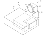
- FIG. 1 is a schematic diagram showing the external configuration of a projection device 10.
- 4 is a schematic cross-sectional view of an optical unit 106 of the projection device 10 shown in FIG. 3.
- FIG. 2 is a diagram showing an example of an installation state of the projection device 10.
- FIG. 13 is a diagram showing another example of an installation state of the projection device 10.
- FIG. 1 is a diagram showing an example of an installation state in which the projection device 10 is embedded in a ceiling.
- FIG. 8 is a diagram showing a state in which the position of a projected image G1 is shifted in the projection device 10 shown in FIG. 7.
- 11A and 11B are diagrams for explaining an example of a shift restriction on a projection image G1.
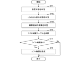
- 11 is a flowchart showing a first processing example of a shift restriction of the projection device 10.
- FIG. 13 is a diagram showing an example of a shift restriction table in the first processing example.
- 13 is a flowchart showing a second processing example in shift restriction of the projection device 10.
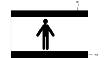
- FIG. 13 is a diagram showing an example of a black band region in a projection image G1.
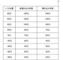
- FIG. 13 is a diagram showing an example of a shift restriction table in the second processing example.
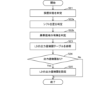
- FIG. 10 is a flowchart showing a first example of a process for limiting an output value of a light source 21 with respect to a shift position of a projection image G1.
- FIG. 13 is a diagram showing an example of an output value limiting table in the first processing example.
- 10 is a flowchart showing a second example of a process for limiting the output value of the light source 21 with respect to a shift position of the projection image G1.
- FIG. 13 is a diagram showing an example of an output value limiting table in the second processing example.
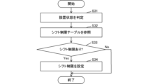
- 13 is a flowchart showing a first modified example of the shift restriction of the projection device 10.
- FIG. 13 is a diagram showing an example of a shift restriction table in the first modified example.
- 11 is a diagram showing a modified example of the configuration of the projection device 10.
- FIG. FIG. 2 is a diagram illustrating an example of a hardware configuration of a personal computer 200.
- Fig. 1 is a schematic diagram showing an example of a projection device 10 according to an embodiment.
- the projection device 10 includes a projection unit 1, a control device 4, and an operation reception unit 2.
- the projection unit 1 is configured by, for example, a liquid crystal projector or a projector using LCOS (Liquid Crystal On Silicon). In the following description, the projection unit 1 is assumed to be a liquid crystal projector.
- the projection unit 1 projects a projection image toward a projection target 6.
- the control device 4 is a control device that controls the projection by the projection device 10.
- the control device 4 is a device that includes a control unit composed of various processors, a communication interface (not shown) for communicating with each unit, and a memory 4a such as a hard disk, SSD (Solid State Drive), or ROM (Read Only Memory), and controls the projection unit 1.
- a control unit composed of various processors, a communication interface (not shown) for communicating with each unit, and a memory 4a such as a hard disk, SSD (Solid State Drive), or ROM (Read Only Memory), and controls the projection unit 1.
- the various processors in the control unit of the control device 4 include a CPU (Central Processing Unit), which is a general-purpose processor that executes programs to perform various processes, a programmable logic device (PLD), which is a processor whose circuit configuration can be changed after manufacture, such as an FPGA (Field Programmable Gate Array), or a dedicated electrical circuit, such as an ASIC (Application Specific Integrated Circuit), which is a processor with a circuit configuration designed specifically to perform specific processes.
- a CPU Central Processing Unit
- PLD programmable logic device
- FPGA Field Programmable Gate Array
- ASIC Application Specific Integrated Circuit
- the structure of these various processors is an electric circuit that combines circuit elements such as semiconductor elements.
- the control unit of the control device 4 may be composed of one of the various processors, or may be composed of a combination of two or more processors of the same or different types (for example, a combination of multiple FPGAs or a combination of a CPU and an FPGA).
- the control device 4 is an example of a "processor" in the present invention.
- the operation reception unit 2 detects instructions from the user by receiving various operations from the user.
- the operation reception unit 2 may be a button, key, joystick, etc. provided on the control device 4, or may be a receiving unit that receives a control signal from a remote controller that remotely operates the control device 4.
- the object to be projected 6 is an object such as a screen or a wall that has a projection surface on which a projected image is displayed by the projection unit 1.
- the projection surface of the object to be projected 6 is a rectangular flat surface.
- the top, bottom, left and right of the object to be projected 6 in FIG. 1 are assumed to be the top, bottom, left and right of the actual object to be projected 6.
- the projection range 11 shown by a dashed line, is the area of the object 6 onto which projection light is irradiated by the projection unit 1.
- the projection range 11 is rectangular.
- the projection range 11 is a part or the entirety of the range within which projection is possible using the projection unit 1.
- the projection unit 1, the control device 4, and the operation reception unit 2 may be realized, for example, by a single device (see, for example, Figs. 3 and 4).
- the projection unit 1, the control device 4, and the operation reception unit 2 may be separate devices that communicate with each other to cooperate.
- FIG. 2 is a schematic diagram showing an example of the internal configuration of the projection unit 1 shown in FIG.
- the projection unit 1 includes a light source 21, a light modulation unit 22, a projection optical system 23, and a control circuit 24.
- the light source 21 includes a light-emitting element such as a laser or an LED (Light Emitting Diode), and emits, for example, white light.
- a light-emitting element such as a laser or an LED (Light Emitting Diode)
- LED Light Emitting Diode
- the light modulation unit 22 is composed of three liquid crystal panels that modulate the three colors of light emitted from the light source 21 and separated into red, blue, and green by a color separation mechanism (not shown) based on image information to emit each color image.
- Each of the three liquid crystal panels may be equipped with a red, blue, or green filter, and the white light emitted from the light source 21 may be modulated by each liquid crystal panel to emit each color image.
- the projection optical system 23 receives light from the light source 21 and the light modulation unit 22 and includes at least one lens, and is composed of, for example, a relay optical system. The light that passes through the projection optical system 23 is projected onto the object 6 to be projected.
- the area of the object 6 onto which light that passes through the entire range of the light modulation unit 22 is irradiated becomes the projectable range where projection by the projection unit 1 is possible. Within this projectable range, the area onto which light that actually passes through the light modulation unit 22 is irradiated becomes the projection range 11. For example, by controlling the size, position, and shape of the area of the light modulation unit 22 through which light passes, the size, position, and shape of the projection range 11 changes within the projectable range.
- the control circuit 24 controls the light source 21, the light modulation unit 22, and the projection optical system 23 based on the display data input from the control device 4, thereby projecting an image based on this display data onto the projection target 6.
- the display data input to the control circuit 24 is composed of three pieces of data: red display data, blue display data, and green display data.
- the control circuit 24 also changes the projection optical system 23 based on a command input from the control device 4, thereby enlarging or reducing the projection range 11 (see FIG. 1) of the projection unit 1.
- the control device 4 may also move the projection range 11 of the projection unit 1 by changing the projection optical system 23 based on an operation from the user received by the operation receiving unit 2.
- the projection device 10 also includes a shift mechanism that mechanically or optically moves the projection range 11 while maintaining the image circle of the projection optical system 23.
- the image circle of the projection optical system 23 is the area through which the projection light incident on the projection optical system 23 passes through the projection optical system 23 appropriately in terms of light intensity loss, color separation, peripheral curvature, etc.
- the shift mechanism is realized by at least one of an optical system shift mechanism that performs an optical system shift and an electronic shift mechanism that performs an electronic shift.
- the optical system shift mechanism is, for example, a mechanism that moves the projection optical system 23 in a direction perpendicular to the optical axis (see, for example, Figures 3 and 4), or a mechanism that moves the light modulation unit 22 in a direction perpendicular to the optical axis instead of moving the projection optical system 23.
- the optical system shift mechanism may also combine the movement of the projection optical system 23 and the movement of the light modulation unit 22.
- the electronic shift mechanism is a mechanism that shifts the pseudo projection range 11 by changing the range through which light is transmitted in the light modulation section 22.
- the projection device 10 may also include a projection direction change mechanism that moves the projection range 11 together with the image circle of the projection optical system 23.
- the projection direction change mechanism is a mechanism that changes the projection direction of the projection unit 1 by changing the orientation of the projection unit 1 through mechanical rotation (see, for example, Figures 3 and 4).
- the control circuit 24 controls the shift mechanism or the projection direction change mechanism based on commands input from the control device 4 to move the projection range 11 of the projection unit 1.
- Fig. 3 is a schematic diagram showing an example of the external configuration of the projection device 10.
- Fig. 4 is a schematic cross-sectional view of the optical unit 106 of the projection device 10 shown in Fig. 3.
- Fig. 4 shows a cross section taken along a plane along the optical path of light emitted from the main body 101 shown in Fig. 3.
- the projection device 10 includes a main body 101 and an optical unit 106 that protrudes from the main body 101.
- the operation reception unit 2, the control device 4, and the light source 21, light modulation unit 22, and control circuit 24 in the projection unit 1 are provided in the main body 101.
- the projection optical system 23 in the projection unit 1 is provided in the optical unit 106.
- the optical unit 106 includes a first member 102 supported by the main body 101 and a second member 103 supported by the first member 102.
- the first member 102 and the second member 103 may be an integrated member.
- the optical unit 106 may be configured to be detachable from the main body 101 (in other words, replaceable).
- the main body 101 has a housing 15 (see FIG. 4) with an opening 15a (see FIG. 4) for passing light through the part connected to the optical unit 106.
- a light source 21 As shown in FIG. 3, inside the housing 15 of the main body 101, there is provided a light source 21, and a light modulation unit 12 including a light modulation section 22 (see FIG. 2) that spatially modulates the light emitted from the light source 21 based on input image data to generate an image.
- a light modulation unit 12 including a light modulation section 22 (see FIG. 2) that spatially modulates the light emitted from the light source 21 based on input image data to generate an image.
- the light emitted from the light source 21 is incident on the light modulation section 22 of the light modulation unit 12, and is spatially modulated by the light modulation section 22 before being emitted.
- the image formed by the light spatially modulated by the light modulation unit 12 passes through the opening 15a of the housing 15 and enters the optical unit 106, and is projected onto the projection target 6, which is the projection object, and the projection image G1 becomes visible to the observer.
- the projection image G1 is an image formed by the projection light irradiated onto the projection range 11.
- the projection image G1 is an example of a "projection image" in this invention.
- the optical unit 106 includes a first member 102 having a hollow portion 2A that is connected to the inside of the main body 101, a second member 103 having a hollow portion 3A that is connected to the hollow portion 2A, a first optical system 121 and a reflecting member 122 that are arranged in the hollow portion 2A, a second optical system 31, a reflecting member 32, a third optical system 33, and a lens 34 that are arranged in the hollow portion 3A, a shift mechanism 105, and a projection direction change mechanism 104.
- the first member 102 is a member having a rectangular cross-sectional outer shape, for example, with the openings 2a and 2b formed on planes perpendicular to each other.
- the first member 102 is supported by the main body 101 with the opening 2a positioned opposite the opening 15a of the main body 101.
- Light emitted from the optical modulation section 22 of the optical modulation unit 12 of the main body 101 passes through the openings 15a and 2a and enters the hollow section 2A of the first member 102.
- direction X1 The direction of light entering hollow portion 2A from main body portion 101 is referred to as direction X1, the opposite direction to direction X1 is referred to as direction X2, and directions X1 and X2 are collectively referred to as direction X.
- direction Z the direction from the front of the paper toward the back and the opposite direction thereto are referred to as direction Z.
- direction Z the direction from the front of the paper toward the back is referred to as direction Z1
- direction Z2 the direction from the back of the paper toward the front is referred to as direction Z2.
- direction Y The direction perpendicular to directions X and Z is referred to as direction Y, and within direction Y, the upward direction in FIG. 4 is referred to as direction Y1, and the downward direction in FIG. 4 is referred to as direction Y2.
- the projection device 10 is disposed so that direction Y2 is the vertical direction.
- the projection optical system 23 shown in FIG. 2 is composed of a first optical system 121, a reflecting member 122, a second optical system 31, a reflecting member 32, a third optical system 33, and a lens 34.
- FIG. 4 shows the optical axis K of the projection optical system 23.
- the first optical system 121, the reflecting member 122, the second optical system 31, the reflecting member 32, the third optical system 33, and the lens 34 are arranged along the optical axis K in this order from the light modulation unit 22 side.
- the first optical system 121 includes at least one lens and guides light traveling in a direction X1 that is incident on the first member 102 from the main body 101 to the reflecting member 122.
- the reflecting member 122 reflects the light incident from the first optical system 121 in the direction Y1.
- the reflecting member 122 is formed of, for example, a mirror.
- the first member 102 has an opening 2b formed on the optical path of the light reflected by the reflecting member 122, and this reflected light passes through the opening 2b and proceeds to the hollow portion 3A of the second member 103.
- the second member 103 is a member with a cross-sectional outer shape that is approximately T-shaped, and an opening 3a is formed in a position facing the opening 2b of the first member 102. Light from the main body 101 that passes through the opening 2b of the first member 102 passes through this opening 3a and enters the hollow portion 3A of the second member 103. Note that the cross-sectional outer shapes of the first member 102 and the second member 103 are arbitrary and are not limited to those described above.
- the second optical system 31 includes at least one lens and guides the light incident from the first member 102 to the reflecting member 32.
- the reflecting member 32 reflects the light incident from the second optical system 31 in the direction X2 and guides it to the third optical system 33.
- the reflecting member 32 is formed of, for example, a mirror.
- the third optical system 33 includes at least one lens and guides the light reflected by the reflecting member 32 to the lens 34.
- Lens 34 is disposed at the end of second member 103 in direction X2 so as to cover opening 3c formed at this end. Lens 34 projects the light incident from third optical system 33 onto projection target 6. Lens 34 is an example of a "projection lens" according to the present invention.
- the projection direction change mechanism 104 is a rotation mechanism that rotatably connects the second member 103 to the first member 102. This projection direction change mechanism 104 configures the second member 103 to be rotatable around a rotation axis (specifically, the optical axis K) that extends in the direction Y. Note that the projection direction change mechanism 104 is not limited to the arrangement position shown in FIG. 4 as long as it can rotate the optical system. Furthermore, the number of rotation mechanisms is not limited to one, and multiple mechanisms may be provided.
- the shift mechanism 105 is a mechanism for moving the optical axis K of the projection optical system (in other words, the optical unit 106) in a direction perpendicular to the optical axis K (direction Y in FIG. 4). Specifically, the shift mechanism 105 is configured to be able to change the position of the first member 102 in direction Y relative to the main body 101.
- the shift mechanism 105 may be one that moves the first member 102 manually, or one that moves the first member 102 electrically.
- Figure 4 shows a state in which the first member 102 has been moved to its maximum extent in the direction Y1 by the shift mechanism 105.
- the first member 102 is moved in the direction Y2 by the shift mechanism 105 from the state shown in Figure 4, the relative position between the center of the image formed by the light modulation unit 22 (in other words, the center of the display surface) and the optical axis K changes, and the projection image G1 projected onto the object to be projected 6 can be shifted (translated) in the direction Y2.
- the shift mechanism 105 may be a mechanism that moves the light modulation unit 22 in the direction Y instead of moving the optical unit 106 in the direction Y. Even in this case, the projection image G1 projected onto the projection target 6 can be moved in the direction Y2.
- FIG. 5 is a diagram showing an example of the installation state of the projection device 10.
- the projection device 10 can be installed in, for example, a non-embedded state on the object 50 on which the projection device 10 is to be installed.
- the object 50 on which the projection device 10 is to be installed is, for example, a "floor”, a "wall”, a “ceiling", a "pillar”, a "pedestal”, etc.
- the non-embedded state includes, for example, a state in which a part of the projection device 10 is installed in contact with the object 50 on which the projection device 10 is to be installed, and a state in which the projection device 10 is installed at a distance from the object 50 on which the projection device 10 is to be installed.
- the state in which the projection device 10 is installed with a part of it in contact with the object 50 on which it is to be installed means, for example, that the projection device 10 is placed on the floor or a pedestal, or that the projection device 10 is attached to a wall, ceiling, or pillar.
- the state in which the projection device 10 is installed at a distance from the object 50 on which it is to be installed means, for example, that the projection device 10 is suspended from the ceiling via a mounting member at a distance.
- the projection device 10 is shown placed on the object 50 to be installed, which is the "floor".
- the projection device 10 shown in FIG. 5 is a simplified illustration, and is composed of a box-shaped main body 101 and a box-shaped optical unit 106.
- the projection device 10 is installed with the main body 101 in contact with the floor, and the optical unit 106 is provided on the main body 101.
- the optical unit 106 is provided with a lens 34, and is configured so that light is projected from the lens 34 towards the object 6 to be projected.
- the light that passes through the lens 34 appropriately is irradiated onto the object 6 to be projected and forms the projection image G1, but when some of the light that is irregularly reflected within the lens 34 is output from the lens 34, it is irradiated onto the floor, for example as shown in FIG. 5, and appears as a brightly lit area (hereafter referred to as a ghost 51).
- the ghost 51 is likely to appear on objects that exist in front of and around the lens 34.
- the area where the ghost 51 appears and its strength (brightness) vary depending on the distance between the object and the lens 34, the strength of the light output from the lens 34, the projection position of the projection image G1 projected from the lens 34, etc.
- FIG. 6 is a diagram showing another example of the installation state of the projection device 10.
- the projection device 10 can be installed, for example, in an embedded state in the object 50 on which it is to be installed.
- the embedded state includes, for example, a state in which the projection device 10 is installed so that a part of it is embedded in the object 50 on which it is to be installed.
- the state in which a part of the projection device 10 is installed inside the object 50 on which it is to be installed means, for example, a state in which a part of the projection device 10 is housed within a specified space formed by a floor, wall, ceiling, pillar, or base.
- the projection device 10 is embedded in a "wall", which is the object 50 on which it is to be installed.
- the projection device 10 is illustrated with a box-shaped main body 101 and a box-shaped optical unit 106, and is installed with the main body 101 housed in a storage space 50a formed in the wall, and the optical unit 106 provided on the main body 101 protruding from the wall.
- the light that passes through the lens 34 appropriately is irradiated onto the object 6 to be projected and forms the projection image G1, but when some of the light that is irregularly reflected within the lens 34 is output from the lens 34, it is irradiated onto the wall, for example as shown in FIG. 6, and appears as a ghost 51.
- ghosts 51 are likely to appear on objects that exist in front of and around the lens 34.
- the area in which the ghost 51 appears and its strength (brightness) vary depending on the distance between the object and the lens 34, the strength of the light output from the lens 34, the projection position of the projection image G1 projected from the lens 34, etc.
- FIGS 7 and 8 are diagrams showing an example of an installation state in which the projection device 10 is embedded in the ceiling. As shown in Figures 7 and 8, the projection device 10 is installed in a projection room 52 with the main body 101 disposed on the "ceiling" which is the object 50 on which it is to be installed, and the optical unit 106 provided on the main body 101 protruding downward from the ceiling.
- FIG. 7 Comparing FIG. 7 and FIG. 8, in FIG. 7, the projection image G1 projected from the lens 34 of the projection device 10 is projected onto an upper region of the projection target 6, whereas in FIG. 8, the projection position of the projection image G1 is projected onto a lower region than the projection position shown in FIG. 7. That is, in FIG. 7, the projection position is shifted so that the projection image G1 is projected onto an upper region closer to the "ceiling", which is the object 50 on which the projection device 10 is installed. On the other hand, in FIG. 8, the projection position is shifted so that the projection image G1 is projected onto a lower region closer to the floor 53 of the projection room 52, which is in a direction away from the ceiling.
- Fig. 9 is a diagram for explaining an example of the shift restriction on the projection image G1.
- the projection device 10 is installed in a state where it is embedded in a "wall", which is an object 50 on which the projection device 10 is to be installed. This installation state is the same as the installation state described in Fig. 6.
- ghost 51 appears according to the projection position of the projection image G1 projected from the lens 34.
- ghost 51 appears on the wall in front of the lens 34.
- ghost 51 appears when the projection position of the projection image G1 is close to the "wall" on which the projection device 10 is installed, becomes weaker (darker) as the projection position becomes farther, and does not appear when it is further away than a predetermined distance. Therefore, by setting the projection position of the projection image G1 to an appropriate projection position in relation to the "wall" on which the projection device 10 is installed, i.e., by limiting the range in which the projection image G1 can be shifted to a predetermined range, it is possible to suppress the appearance of ghost 51.
- the direction in which the "wall” which is the object 50 on which the projection device 10 is installed extends is direction X
- the direction perpendicular to the "wall” is direction Y
- Directions X and Y are perpendicular to the optical axis K of the lens 34.
- the appearance of ghosts 51 on the "wall” can be suppressed by limiting the range in which the projection image G1 can be shifted in direction Y to a predetermined range.
- the shift range of the projection image G1 in the direction of the "wall” on which the projection device 10 is installed that is, the shift range of the projection image G1 in the -Y direction in direction Y
- the appearance of ghosts 51 can be suppressed by limiting the shift so that the bottom end 55 of the projection image G1 is projected above (in the +Y direction) the shaded area 56.
- the projection device 10 is installed on the floor below the projection device 10, the downward shift of the projection image G1 projected from the lens 34 is limited. Also, if the projection device 10 is installed on a wall to the right of the projection device 10, the rightward shift of the projection image G1 projected from the lens 34 is limited. Also, if the projection device 10 is installed on the ceiling above the projection device 10, the upward shift of the projection image G1 projected from the lens 34 is limited.
- FIG. 9 shows an installation state in which the projection device 10 is embedded in a "wall", which is the object 50 on which the projection device 10 is to be installed, it may also be installed on a "floor” as described in FIG. 5.
- the projection device 10 is installed on a "floor"
- the distance between the lens 34 and the object 50 on which the projection device 10 is to be installed is longer than when the projection device 10 is embedded in a "wall”, and the shift range is limited according to that distance.
- the limitations on the shift range are relaxed and the range over which the projection device 10 can be shifted is wider.
- the objects on which the ghost 51 appears are not limited to these.
- the shift range of the projected image G1 may be limited according to the distance between the lens 34 and the object closest to the lens 34. In this way, depending on the installation situation of the projection device 10, the object closest to the lens 34 may be the object 50 to be installed, or another object such as a plate placed nearby.
- First processing example of shift restriction> 10 is a flowchart showing a first processing example in the shift restriction of the projection device 10.
- the projection device 10 starts executing this processing, for example, when the projection device 10 is started up.
- the projection device 10 determines the installation state of the projection device 10 (step S11).
- the installation state of the projection device 10 refers to, for example, whether the projection device 10 is installed in a non-embedded state (see FIG. 5) or embedded state (see FIG. 6 and FIG. 7) in the object 50 to be installed.
- the projection device 10 determines the installation state based on, for example, the setting state of an installation mode switch that is set when the projection device 10 is installed.
- the installation mode switch is set by a mode selection operation by the user.
- the projection device 10 may also determine the installation state based on sensing data from a camera or a three-dimensional sensor (lidar) mounted on the projection device 10.
- the projection device 10 may also be equipped with a remote control receiver in each of the main body 101 and the optical unit 106, for example, and may determine the installation state based on the reception state of a signal based on an external remote control operation (which remote control receiver receives the signal).
- the projection device 10 determines the state of the output value of the light source 21 (laser diode (LD)) (step S12).
- the state of the output value of the light source 21 is determined, for example, by determining what percentage of the maximum output value of the light source 21 the output value is.
- the projection device 10 refers to a shift limit table for setting the shift range of the projection image G1 based on the installation state of the projection device 10 and the state of the output value of the light source 21 (step S13).
- the shift limit table is stored in advance in the memory 4a as measured shift limit data.
- the shift limit table will be described later with reference to FIG. 11.
- the projection device 10 refers to the shift restriction table to determine whether or not there is a shift restriction on the projection position of the projection image G1 projected from the lens 34 (step S14).
- step S14 If there is no shift limit on the projection position of the projection image G1 in step S14 (step S14: No), the projection device 10 ends this process. If there is a shift limit on the projection position of the projection image G1 in step S14 (step S14: Yes), the projection device 10 sets a shift limit on the projection position of the projection image G1 projected from the lens 34 (step S15). In this example, the presence or absence and the degree of the shift limit on the projection image G1 are set based on the installation state of the projection device 10 and the state of the output value of the light source 21.
- this processing is started when the projection device 10 is started, but this is not limited to the above.
- this processing may be executed repeatedly when the projection device 10 is started.
- This processing may also be executed when a change in the installation state of the projection device 10 is detected or when a change in the output value of the light source 21 is detected.
- this processing may also be executed when an instruction to shift the projection image G1 is received from the user.
- Fig. 11 is a diagram showing an example of the shift limit table in the above-mentioned processing example 1.
- the shift limit table 61 shows the shift limit value of the projection device 10 in a non-embedded state and the shift limit value of the projection device 10 in a buried state at a predetermined output value of the light source 21.
- the limit of the shift range of the projected image G1 is set to -20% of the lower shift limit when the projection device 10 is in the non-embedded state.
- the limit of the shift range of the projected image G1 is set to -15% of the lower shift limit.
- a negative (-) lower shift limit refers to a shift limit in the -Y direction in the Y direction, for example, as described in FIG. 9, that is, a shift limit in the direction of the object 50 on which the projection device 10 is installed.
- a lower shift limit of -20% is a ratio to the maximum shift amount (-100%) in the -Y direction, and indicates that a ghost 51 appears when the shift amount in the -Y direction exceeds -20%.
- the shift range limit is set to -25% of the lower shift limit value when the projection device 10 is in a non-embedded state, and the shift range limit is set to -20% of the lower shift limit value when the projection device 10 is in a recessed state.
- the shift range limit is set to -30% of the lower shift limit value when the projection device 10 is in a non-embedded state, and the shift range limit is set to -25% of the lower shift limit value when the projection device 10 is in a recessed state.
- the shift range limit is set to -35% of the lower shift limit value when the projection device 10 is in a non-embedded state, and the shift range limit is set to -30% of the lower shift limit value when the projection device 10 is in a recessed state.
- the limit of the shift range is set to -40% of the lower shift limit when the projection device 10 is not embedded, and the limit of the shift range is set to -35% of the lower shift limit when the projection device 10 is embedded.
- the object 50 on which the projection device 10 is installed is located below the lens 34, so a shift restriction table 61 that restricts the downward shift range of the projection image G1 is stored in the memory 4a, but a shift restriction table to be used when a shift restriction in another direction is required may be prepared and stored in the memory 4a.
- the projection device 10 limits the range within which the projection image G1 can be shifted based on information related to the installation state of the projection device 10 and information related to the output value of the light source 21.
- ⁇ Second processing example of shift restriction> 12 is a flowchart showing a second processing example of the shift restriction of the projection device 10.
- the projection device 10 starts executing this processing, for example, when the projection device 10 is started up, similar to the first processing example of the shift restriction.
- step S11 to step S12a are the same as the processes from step S11 to step S12 in the first processing example described in FIG. 10. Therefore, the description of steps S11 to S12a will be omitted.
- the projection device 10 judges whether or not black band areas exist in the upper and lower regions of the projection image G1 in order to determine the content of the currently projected projection image G1 (step S12b).
- the black band areas in the upper and lower regions of the projection image G1 are dark areas that appear black at the top and bottom of the image, such as when projecting a horizontally long movie image. Images with black band areas will be described later with reference to FIG. 13.
- the projection device 10 refers to a shift limit table for setting the shift range of the projection image G1 based on the installation state of the projection device 10, the state of the output value of the light source 21, and the presence or absence of a black band area in the projection image G1 (step S13).
- the shift limit table to be referred to will be described later with reference to FIG. 14.
- step S14 to step S15 in this second processing example are the same as the processes from step S14 to step S15 in the first processing example described in FIG. 10. For this reason, the description of steps S14 to S15 is omitted.
- the presence or absence and the degree of shift restriction of the projected image G1 are set based on the installation state of the projection device 10, the state of the output value of the light source 21, and the presence or absence of dark areas (black band areas) in the projected image G1.
- FIG. 13 is a diagram showing an example of a black belt area in a projection image G1.
- the black belt area 62 is provided in a belt shape that crosses from the left end to the right end at the upper and lower ends of the projection image G1.
- the brightness of the projection image G1 with the black belt area 62 is weaker than the brightness of the projection image G1 without the black belt area 62, so the restriction of the shift range of the projection image G1 is relaxed.
- the brightness of the projection image G1 may be determined from the information on the presence or absence of the black belt area 62, or may be determined from a representative value of the pixel values.
- the representative value of the pixel values includes, for example, the average value of the brightness of each pixel, the sum of the brightness of the pixels of the entire image, the median value of the brightness of the pixels, the most frequent value, etc.
- the representative value of the pixel values of each frame may be obtained and the brightness may be determined from the representative value.
- Fig. 14 is a diagram showing an example of the shift limit table in the second processing example described above.
- the shift limit table 63 shown in Fig. 14 is a shift limit table to be referred to when black band areas exist in the upper and lower areas of the projection image G1.
- the shift limit table 63 shows the shift limit value of the projection device 10 in a non-embedded state and the shift limit value of the projection device 10 in a buried state at a predetermined output value of the light source 21.
- the limit of the shift range of the projection image G1 is set to -25% of the lower shift limit when the projection device 10 is in a non-embedded state.
- the limit of the shift range of the projection image G1 is set to -20% of the lower shift limit.
- the limit of the shift range is set to -30% of the lower shift limit when the projection device 10 is in a non-embedded state, and the limit of the shift range is set to -25% of the lower shift limit when the projection device 10 is in an embedded state.
- the limit of the shift range is set to -35% of the lower shift limit when the projection device 10 is in a non-embedded state, and the limit of the shift range is set to -30% of the lower shift limit when the projection device 10 is in an embedded state.
- the limit of the shift range is set to -40% of the lower shift limit value when the projection device 10 is not embedded, and the limit of the shift range is set to -35% of the lower shift limit value when the projection device 10 is embedded.
- the limit of the shift range is set to -45% of the lower shift limit value when the projection device 10 is not embedded, and the limit of the shift range is set to -40% of the lower shift limit value when the projection device 10 is embedded. Note that, in the second processing example, as in the first processing example, the object 50 on which the projection device 10 is to be installed is located below the lens 34.
- step S12b in the second processing example of FIG. 12 that there are no black band areas in the upper or lower areas of the projected image G1, the shift limit table 61 of FIG. 11 is referenced, as in the first processing example of FIG. 10.
- the shift restriction is described for the case where dark areas (black band areas) that weaken the brightness of the image are present in the upper and lower regions of the projected image G1, and the object 50 on which the projection device 10 is to be installed is present below the lens 34, but this is not limited to the above.
- the dark areas that weaken the brightness of the image may exist not only in the upper and lower end regions of the projected image G1, but also in the left and right end regions, for example. Therefore, a shift restriction may be imposed on the projected image G1 according to the direction in which the dark area exists among the multiple end regions of the projected image G1.
- the projection device 10 restricts the range within which the projection image G1 can be shifted based on information about the installation state of the projection device 10, information about the output value of the light source 21, and information about the brightness of the content of the projection image G1.
- the projection image G1 that takes into account the brightness of the content can be displayed at a distance greater than a predetermined distance according to the output value of the light source 21 from objects present around the lens 34 of the projection device 10. This makes it possible to more appropriately suppress ghosts 51 that may appear on objects around the lens 34 of the projection device 10 based on the projection light, for example ghosts 51 that may appear on the object 50 (floor, wall, etc.) on which the projection device 10 is installed.
- ⁇ First Processing Example of Limiting Output Value of Light Source 21> 15 is a flowchart showing a first example of a process for limiting the output value of the light source 21 with respect to the shift position of the projection image G1.
- the projection device 10 starts executing this process, for example, when the projection device 10 is started up.
- the projection device 10 determines the installation state of the projection device 10 (step S21).
- the installation state of the projection device 10 refers to, for example, whether the projection device 10 is installed in a non-embedded state or embedded state in the object 50 on which the projection device 10 is to be installed.
- the projection device 10 determines the shift position of the projection image G1 projected from the lens 34 onto the projection target 6 (step S22).
- the shift position of the projection image G1 refers to the shift position in the direction X or direction Y in the projection device 10 installed as shown in FIG. 9, for example.
- the projection device 10 refers to an output value limit table for setting the output value of the light source 21 (LD) based on the installation state of the projection device 10 and the shift position of the projection image G1 (step S23).
- the output value limit table is stored in advance in the memory 4a as measured output value limit data.
- the output value limit table will be described later with reference to FIG. 16.
- the projection device 10 refers to the output value limit table to determine whether or not there is an output value limit on the projection light output from the light source 21 (step S24).
- step S24: No If there is no output value limit on the projection light from the light source 21 in step S24 (step S24: No), the projection device 10 ends this process. If there is an output value limit on the projection light from the light source 21 in step S24 (step S24: Yes), the projection device 10 sets an output value limit on the projection light output from the light source 21 (step S25). In this example, the presence or absence and the degree of the output value limit on the light source 21 are set based on the installation state of the projection device 10 and the shift position of the projection image G1.
- this process may be executed repeatedly after startup, when a change in the installation state of the projection device 10 is detected or when a change in the shift position of the projection image G1 is detected, or when an output value instruction is received from the user.
- Fig. 16 is a diagram showing an example of the output value limit table in the above-mentioned processing example 1.
- the output value limit table 71 shows the output limit value of the projection device 10 in the non-embedded state and the output limit value of the projection device 10 in the embedded state at a predetermined shift position of the projection image G1.
- the limit of the output value of the projection light from the light source 21 is set to 100% whether the projection device 10 is in a non-embedded state or an embedded state.
- the shift position is the shift position in the direction Y of the projection device 10 installed as shown in FIG. 9.
- a plus (+) shift position means that the shift in the direction Y is in the +Y direction, that is, a shift in the direction away from the object 50 on which the projection device 10 is installed.
- a minus (-) shift position means that the shift in the direction Y is in the -Y direction, that is, a shift in the direction toward the object 50 on which the projection device 10 is installed.
- a shift position of 80% means that the shift in the +Y direction is a position that is 80% of the maximum shift position (+100%).
- a limit of 100% output value means that no ghost 51 appears even if the output value of the light source 21 is set to the maximum output value (100%).
- the output value limit of the projection light from the light source 21 is set to 80% when the projection device 10 is in a non-embedded state, and the output value limit of the projection light from the light source 21 is set to 70% when the projection device 10 is in a embedded state.
- An output value limit of 80% indicates that a ghost 51 appears when the output value of the light source 21 exceeds 80%.
- the output value limit is set to 70% when the projection device 10 is in a non-embedded state, and the output value limit is set to 60% when the projection device 10 is in a embedded state.
- the output value limit is set to 60% when the projection device 10 is in a non-embedded state, and the output value limit is set to 50% when the projection device 10 is in an embedded state.
- a shift position of -20% means that the shift in the -Y direction has shifted to a position that is -20% of the maximum shift position (-100%).
- the output value limit is set to 50% when the projection device 10 is in a non-embedded state, and the output value limit is set to 40% when the projection device 10 is in an embedded state.
- the output value limit is set to 40% when the projection device 10 is in a non-embedded state, and the output value limit is set to 30% when the projection device 10 is in an embedded state.
- the output value limit is set to 30% when the projection device 10 is in a non-embedded state, and the output value limit is set to 20% when the projection device 10 is in an embedded state.
- the distance between the lens 34 and the object 50 on which the projection device 10 is installed is shorter than when the projection device 10 is not embedded, making it easier for ghost 51 to appear, and strong restrictions are imposed on the output value of the light source 21.
- the projection device 10 limits the output value of the light source 21 based on information related to the installation state of the projection device 10 and information related to the shift position of the projection image G1. With this configuration, it is possible to limit the range that the light source 21 can output, depending on the shift position of the projection image G1 projected from the projection device 10. This makes it possible to suppress ghosts 51 that may appear on objects around the lens 34 of the projection device 10 based on the projection light, for example ghosts 51 that may appear on the object 50 (floor, wall, etc.) on which the projection device 10 is installed.
- ⁇ Second Example of Processing for Limiting Output Value of Light Source 21> 17 is a flowchart showing a second example of the process of limiting the output value of the light source 21 with respect to the shift position of the projection image G1.
- the projection device 10 starts the execution of this process, for example, when the projection device 10 is started, in the same manner as the first example of the process of limiting the output value.
- step S21 to step S22a are the same as the processes from step S21 to step S22 in the first processing example described in FIG. 15. Therefore, the description of steps S21 to S22a will be omitted.
- the projection device 10 determines whether or not there are black band areas at the top and bottom of the projection image G1 in order to determine the content of the currently projected projection image G1 (step S22b).
- the black band areas at the top and bottom of the projection image G1 are dark areas that appear black at the top and bottom of the image, such as when projecting a horizontally long movie image, as described above in FIG. 13.
- the projection device 10 refers to an output value limit table for setting the output value of the light source 21 (LD) based on the installation state of the projection device 10, the shift position of the projection image G1, and the presence or absence of a black band area in the projection image G1 (step S23).
- the output value limit table will be described later with reference to FIG. 18.
- step S24 to step S25 in this second processing example are the same as the processes from step S24 to step S25 in the first processing example described in FIG. 15. For this reason, the description of steps S24 to S25 will be omitted.
- the presence or absence and the degree of output value limiting of the light source 21 are set based on the installation state of the projection device 10, the shift position of the projected image G1, and the presence or absence of dark areas (black band areas) in the projected image G1.
- Fig. 18 is a diagram showing an example of the output value limit table in the second processing example described above.
- the output value limit table 72 shown in Fig. 18 is an output value limit table to be referenced when black band areas exist in the upper and lower areas of the projection image G1.
- the output value limit table 72 shows the output limit value of the projection device 10 in a non-embedded state and the output limit value of the projection device 10 in an embedded state at a predetermined shift position of the projection image G1.
- the limit on the output value of the projection light from the light source 21 is set to 100% whether the projection device 10 is in a non-embedded state or an embedded state.
- the limit on the output value of the light source 21 is set to 85% when the projection device 10 is in a non-embedded state, and the limit on the output value of the light source 21 is set to 75% when the projection device 10 is in an embedded state.
- the limit on the output value is set to 75% when the projection device 10 is in a non-embedded state, and the limit on the output value is set to 65% when the projection device 10 is in an embedded state.
- the limit on the output value is set to 65% when the projection device 10 is in a non-embedded state, and the limit on the output value is set to 55% when the projection device 10 is in an embedded state.
- the output value limit is set to 55% when the projection device 10 is in a non-embedded state, and the output value limit is set to 45% when the projection device 10 is in an embedded state.
- the output value limit is set to 45% when the projection device 10 is in a non-embedded state, and the output value limit is set to 35% when the projection device 10 is in an embedded state.
- the output value limit is set to 35% when the projection device 10 is in a non-embedded state, and the output value limit is set to 25% when the projection device 10 is in an embedded state.
- the output value of the light source 21 is more strongly restricted as the projected image G1 is shifted closer to the object 50 on which the projection device 10 is installed, and the output value of the light source 21 is more strongly restricted when the projection device 10 is installed in an embedded state than when it is not embedded, which is similar to the output value restriction table 71 referenced in the first processing example above.
- the output value restriction rate [%] is compared between the output value restriction table 72 in FIG. 18 and the output value restriction table 71 in FIG. 16
- the output value restriction table 72 has black band areas in the upper and lower regions and the brightness of the projected image G1 is correspondingly weaker, resulting in a looser output value restriction rate than that of the output value restriction table 71.
- step S22b in the second processing example of FIG. 17 that there are no black band areas in the upper or lower areas of the projection image G1
- the output value limit table 71 of FIG. 16 is referenced, as in the first processing example of FIG. 15.
- the projection device 10 limits the output value of the light source 21 based on information related to the installation state of the projection device 10, information related to the shift position of the projection image G1, and information related to the brightness of the content of the projection image G1.
- ⁇ First Modification of Shift Restriction> 19 is a flowchart showing a first modified example of the shift restriction of the projection device 10.
- the presence or absence and the degree of the shift restriction of the projection image G1 are set based only on the installation state of the projection device 10.
- the projection device 10 starts execution of this process, for example, when the projection device 10 is started, as in the first processing example of the shift restriction described above.
- step S31 is the same as the processing in step S11 in the first processing example described in FIG. 10.
- the projection device 10 refers to a shift limit table to set the shift range of the projection image G1 based on the installation state of the projection device 10 (step S32).
- the shift limit table will be described later with reference to FIG. 20.
- the projection device 10 refers to the shift limit table to determine whether or not there is a shift limit for the projection image G1 projected from the lens 34 (step S14).
- step S33 to step S34 in this modified example are the same as the processes from step S14 to step S15 in the first processing example described in FIG. 10.
- Fig. 20 is a diagram showing an example of the shift limit table in the above-mentioned modified example 1.
- the shift limit table 81 shows the shift limit value of the projection device 10 in a non-embedded state and the shift limit value of the projection device 10 in a buried state.
- the limit of the shift range of the projection image G1 is set to -20% of the lower shift limit.
- the limit of the shift range of the projection image G1 is set to -15% of the lower shift limit. This indicates that in the not embedded state, ghost 51 appears when the shift amount of the projection image G1 in the -Y direction exceeds -20%, and in the embedded state, ghost 51 appears when the shift amount of the projection image G1 in the -Y direction exceeds -15%.
- the distance between the lens 34 and the object 50 on which the projection device 10 is installed is shorter than when the projection device 10 is not embedded, so ghost 51 is more likely to appear, and a strong limit is imposed on the shift range of the projection image G1.
- the projection device 10 limits the range within which the projection image G1 can be shifted based on information related to the installation state of the projection device 10.
- the information on the shift restriction includes, for example, information on the change in the output value of the light source 21 and information on the change in the installation state of the projection device 10.
- the information on the change in the output value of the light source 21 is information that the shift restriction of the projection image G1 becomes stronger when the output value of the light source 21 increases, and the shift restriction of the projection image G1 becomes looser when the output value of the light source 21 decreases.
- the information on the change in the installation state of the projection device 10 is information that the shift restriction of the projection image G1 becomes stronger when the projection device 10 is in an embedded state, and the shift restriction of the projection image G1 becomes looser when the projection device 10 is in a non-embedded state.
- the projection device 10 performs control to maintain the shift state of the projected image G1. For example, assume that the output value of the light source 21 increases during the projection of the projected image G1. Even if this change in output value causes the current shift position of the projected image G1 to move out of the shiftable area, the projection device 10 maintains the current shift position during the projection of the projected image G1. In other words, even if the output value of the light source 21 increases and a ghost 51 would appear if the current shift position were maintained, the position of the projected image G1 is not changed and is maintained as is during projection.
- the projection position of the projection image G1 is maintained at the same position, so it is possible to prevent the uncomfortable feeling that the position of the projection image G1 moves during projection.
- control is performed to change the shifted state of the projected image G1 according to information related to the shift restrictions. For example, assume that while the shifted state of the projected image G1 is maintained, the user performs an operation to change the shift position of the projected image G1. In this case, even during projection of the projected image G1, the shift position of the projected image G1 is changed so that the position of the projected image G1 is within the shiftable area for the changed output value of the light source 21.
- FIG. 21 is a diagram showing a modified example of the configuration of the projection device 10.
- the control device 4 that controls the projection device 10 is provided in the main body 101 of the projection device 10, but this is not limited to this.
- the control device 4 may be, for example, a processor 201 (see FIG. 13) mounted on a personal computer 200 that is external to the projection device 10.
- the processor 201 may have all or part of the functions of the control device 4 in the projection device 10.
- the personal computer 200 is connected to the projection device 10 via a signal line 10a so as to be able to communicate with the projection device 10.
- the personal computer 200 may be connected to the projection device 10 so as to be able to wirelessly communicate with the projection device 10.
- Fig. 22 is a diagram showing an example of a hardware configuration of a personal computer 200.
- the personal computer 200 shown in Fig. 21 includes a processor 201, a memory 202, a communication interface 203, and a user interface 204.
- the processor 201, the memory 202, the communication interface 203, and the user interface 204 are connected by, for example, a bus 209.
- the processor 201 is a circuit that performs signal processing, and is, for example, a CPU that controls the entire personal computer 200.
- the processor 201 may also be realized by other digital circuits such as an FPGA or a DSP (Digital Signal Processor).
- the processor 201 may also be realized by combining multiple digital circuits.
- Memory 202 includes, for example, a main memory and an auxiliary memory.
- the main memory is, for example, a RAM (Random Access Memory).
- the main memory is used as a work area for processor 201.
- the auxiliary memory is a non-volatile memory such as a magnetic disk, optical disk, or flash memory.
- Various programs that operate the personal computer 200 are stored in the auxiliary memory.
- the programs stored in the auxiliary memory are loaded into the main memory and executed by the processor 201.
- the auxiliary memory may also include portable memory that is removable from the personal computer 200.
- Portable memory includes memory cards such as a Universal Serial Bus (USB) flash drive or a Secure Digital (SD) memory card, and an external hard disk drive.
- USB Universal Serial Bus
- SD Secure Digital
- the communication interface 203 is a communication interface that communicates with the outside of the personal computer 200 (for example, the external communication unit of the projection device 10).
- the communication interface 203 is controlled by the processor 201.
- the communication interface 203 may be a wired communication interface that performs wired communication, a wireless communication interface that performs wireless communication, or may include both a wired communication interface and a wireless communication interface.
- the user interface 204 includes, for example, an input device that accepts operational input from the user and an output device that outputs information to the user.
- the input device can be realized, for example, by a pointing device (for example, a mouse), a key (for example, a keyboard), or a remote control.
- the output device can be realized, for example, by a display or a speaker.
- the input device and the output device may also be realized by a touch panel or the like.
- the user interface 204 is controlled by the processor 201.
- the control method described in the above embodiment can be realized by executing a prepared control program on a computer.
- This control program is recorded on a computer-readable storage medium and executed by reading it from the storage medium.
- this control program may be provided in a form stored in a non-transitory storage medium such as a flash memory, or may be provided via a network such as the Internet.
- the computer that executes this control program may be included in the control device, or may be included in an electronic device such as a smartphone, tablet terminal, or personal computer that can communicate with the control device, or may be included in a server device that can communicate with these control devices and electronic devices.
- projection device 10 and personal computer 200 may perform control to limit the enlargement of the projected image depending on the installation state of projection device 10 instead of or in addition to shifting the projected image.
Landscapes
- Engineering & Computer Science (AREA)
- Physics & Mathematics (AREA)
- General Physics & Mathematics (AREA)
- Computer Hardware Design (AREA)
- Theoretical Computer Science (AREA)
- Multimedia (AREA)
- Signal Processing (AREA)
- Chemical & Material Sciences (AREA)
- Crystallography & Structural Chemistry (AREA)
- Geometry (AREA)
- Transforming Electric Information Into Light Information (AREA)
- Projection Apparatus (AREA)
Abstract
Description
投影レンズ及びプロセッサを備え、投影像をシフト可能な投影装置であって、
上記プロセッサは、
上記投影装置の設置状態に関する情報を取得し、
上記設置状態に応じて、上記投影像のシフトに制限をかける制御を行う、
投影装置。
(1)に記載の投影装置であって、
上記設置状態は、上記投影レンズと、上記投影装置の設置対象の物体と、の位置関係に関する状態である、
投影装置。
(1)又は(2)に記載の投影装置であって、
上記設置状態は、上記投影装置の設置対象の物体に上記投影装置の少なくとも一部が埋め込まれた埋め込み状態を含む、
投影装置。
(3)に記載の投影装置であって、
上記プロセッサは、上記埋め込み状態において、上記埋め込み状態と異なる上記設置状態よりも上記シフトに強い制限をかける、
投影装置。
(1)~(4)のいずれか1つに記載の投影装置であって、
上記設置状態に関する情報は、上記投影レンズと、上記投影装置以外の上記投影レンズと最も近い物体と、の距離に関する情報を含み、
上記プロセッサは、上記距離に応じて上記シフトに制限をかける、
投影装置。
(1)~(4)のいずれか1つに記載の投影装置であって、
上記設置状態に関する情報は、上記投影レンズと、上記投影装置の設置対象の物体と、の距離に関する情報を含み、
上記プロセッサは、上記距離に応じて上記シフトに制限をかける、
投影装置。
(1)~(6)のいずれか1つに記載の投影装置であって、
上記プロセッサは、上記投影レンズと、上記投影装置の設置対象の物体と、の位置関係に応じた方向における上記シフトに制限をかける、
投影装置。
(1)~(7)のいずれか1つに記載の投影装置であって、
上記プロセッサは、上記設置状態と、上記投影装置の光源の状態と、に応じて上記シフトに制限をかける制御を行う、
投影装置。
(8)に記載の投影装置であって、
上記光源の状態は、上記光源の出力値の状態を含む、
投影装置。
(9)に記載の投影装置であって、
上記プロセッサは、上記出力値が第1出力値である場合に、上記出力値が上記第1出力値より低い第2出力値である場合よりも上記シフトに強い制限をかける、
投影装置。
(1)~(6)のいずれか1つに記載の投影装置であって、
上記プロセッサは、上記シフトの状態に基づいて上記投影装置の光源の出力値を制御する、
投影装置。
(1)~(11)のいずれか1つに記載の投影装置であって、
上記プロセッサは、上記設置状態と、上記投影像の画像コンテンツと、に応じて上記シフトに制限をかける制御を行う、
投影装置。
(12)に記載の投影装置であって、
上記プロセッサは、上記設置状態と、上記投影像の画像コンテンツの明るさと、に応じて上記シフトに制限をかける制御を行う、
投影装置。
(13)に記載の投影装置であって、
上記プロセッサは、上記投影像の画像コンテンツにおける複数の端部領域の明るさに応じた方向における上記シフトに制限をかける、
投影装置。
(1)~(14)のいずれか1つに記載の投影装置であって、
上記プロセッサは、上記投影像の投影中に上記シフトの制限に関する情報が変化した場合、上記シフトの状態を維持する、
投影装置。
(15)に記載の投影装置であって、
上記プロセッサは、上記シフトの状態を維持している状態において上記シフトに関するユーザ操作があった場合は、上記シフトの制限に関する情報に応じて上記シフトの状態を変化させる、
投影装置。
(1)から(16)のいずれか1項に記載の投影装置であって、
上記シフトは、上記投影レンズの光軸方向に対して垂直な方向へのシフトである、
投影装置。
投影レンズ及びプロセッサを備え、投影像をシフト可能な投影装置の制御方法であって、
上記プロセッサが、
上記投影装置の設置状態に関する情報を取得し、
上記設置状態に応じて、上記投影像のシフトに制限をかける制御を行う、
制御方法。
投影レンズ及びプロセッサを備え、投影像をシフト可能な投影装置の制御プログラムであって、
上記プロセッサに、
上記投影装置の設置状態に関する情報を取得し、
上記設置状態に応じて、上記投影像のシフトに制限をかける制御を行う、
処理を実行させるための制御プログラム。
図1は、実施形態の投影装置10の一例を示す模式図である。図1に示すように、投影装置10は、投影部1と、制御装置4と、操作受付部2と、を備える。投影部1は、例えば液晶プロジェクタ又はLCOS(Liquid Crystal On Silicon)を用いたプロジェクタ等によって構成される。以下では、投影部1が液晶プロジェクタであるものとして説明する。投影部1は、被投影物6に向けて投影画像を投影する。
図2は、図1に示す投影部1の内部構成の一例を示す模式図である。
図3は、投影装置10の外観構成の一例を示す模式図である。図4は、図3に示す投影装置10の光学ユニット106の断面模式図である。図4は、図3に示す本体部101から出射される光の光路に沿った面での断面を示している。
次に、投影装置10が使用される際の投影装置10の設置状態について説明する。図5は、投影装置10の設置状態の一例を示す図である。図5に示すように、投影装置10は、設置対象の物体50に例えば非埋め込みの状態で設置され得る。設置対象の物体50は、例えば「床」や「壁」や「天井」や「柱」や「台座」などである。非埋め込みの状態とは、例えば設置対象の物体50上に投影装置10の一部が接して設置されている状態や、設置対象の物体50から距離を空けて投影装置10が設置されている状態などが含まれる。
次に、ゴースト51を出現させないための投影装置10の設置状態について説明する。図7及び図8は、投影装置10が天井に埋め込まれた設置状態の一例を示す図である。図7及び図8に示すように、投影装置10は、本体部101が設置対象の物体50である「天井」の上に配置され、本体部101上に設けられた光学ユニット106が天井から下方へ突出した状態で投影部屋52内に設置されている。
次に、ゴースト51を出現させないための投影画像G1のシフト制限について説明する。図9は、投影画像G1のシフト制限の一例を説明するための図である。図9に示すように、投影装置10は、設置対象の物体50である「壁」に埋め込まれた状態で設置されている。この設置状態は、図6で説明した場合と同様の設置状態である。
図10は、投影装置10のシフト制限における第1処理例を示すフローチャートである。投影装置10は、例えば投影装置10の起動時に本処理の実行を開始する。
図11は、上述した第1処理例におけるシフト制限テーブルの一例を示す図である。図11に示すように、シフト制限テーブル61は、光源21の所定の出力値における非埋め込み状態の投影装置10のシフト制限値と、埋め込み状態の投影装置10のシフト制限値とを示す。
図12は、投影装置10のシフト制限における第2処理例を示すフローチャートである。投影装置10は、上記シフト制限の第1処理例と同様に例えば投影装置10の起動時に本処理の実行を開始する。
図13は、投影画像G1における黒帯領域の一例を示す図である。図13に示すように、黒帯領域62は、投影画像G1の上下端部にそれぞれ左端から右端まで横切る帯状に設けられる。黒帯領域62が設けられている投影画像G1の明るさは、黒帯領域62が設けられていない投影画像G1の明るさよりも弱いため、投影画像G1のシフト範囲の制限が緩くなる。投影画像G1の明るさは、黒帯領域62の有無の情報から判定してもよいし、画素値の代表値から判定してもよい。画素値の代表値には、例えば各画素の明るさの平均値、画像全体の画素の明るさの合計値、画素の明るさの中央値、最頻値等が含まれる。また、投影画像G1が動画の場合には、例えば各フレームの画素値の代表値を求め、それらの代表値から判定してもよい。
図14は、上述した第2処理例におけるシフト制限テーブルの一例を示す図である。図14に示すシフト制限テーブル63は、投影画像G1の上下領域に黒帯領域が存在する場合に参照するシフト制限テーブルである。図14に示すように、シフト制限テーブル63は、光源21の所定の出力値における非埋め込み状態の投影装置10のシフト制限値と、埋め込み状態の投影装置10のシフト制限値とを示す。
図15は、投影画像G1のシフト位置に対する光源21の出力値制限の第1処理例を示すフローチャートである。投影装置10は、例えば投影装置10の起動時に本処理の実行を開始する。
図16は、上述した第1処理例における出力値制限テーブルの一例を示す図である。図16に示すように、出力値制限テーブル71は、投影画像G1の所定のシフト位置における非埋め込み状態の投影装置10の出力制限値と、埋め込み状態の投影装置10の出力制限値とを示す。
図17は、投影画像G1のシフト位置に対する光源21の出力値制限の第2処理例を示すフローチャートである。投影装置10は、上記出力値制限の第1処理例と同様に例えば投影装置10の起動時に本処理の実行を開始する。
図18は、上述した第2処理例における出力値制限テーブルの一例を示す図である。図18に示す出力値制限テーブル72は、投影画像G1の上下領域に黒帯領域が存在する場合に参照する出力値制限テーブルである。図18に示すように、出力値制限テーブル72は、投影画像G1の所定のシフト位置における非埋め込み状態の投影装置10の出力制限値と、埋め込み状態の投影装置10の出力制限値とを示す。
図19は、投影装置10のシフト制限の第1変形例を示すフローチャートである。本変形例では、投影装置10の設置状態のみに基づいて投影画像G1のシフト制限の有無や程度が設定される。投影装置10は、上記シフト制限の第1処理例と同様に例えば投影装置10の起動時に本処理の実行を開始する。
図20は、上述した第1変形例におけるシフト制限テーブルの一例を示す図である。図20に示すように、シフト制限テーブル81は、非埋め込み状態の投影装置10のシフト制限値と、埋め込み状態の投影装置10のシフト制限値を示す。
次に、投影画像G1の投影中において投影画像G1のシフトの制限に関する情報に変化があった場合のシフト制限の制御について説明する。シフトの制限に関する情報には、例えば光源21の出力値の変化に関する情報や、投影装置10の設置状態の変化に関する情報などが含まれる。光源21の出力値の変化に関する情報とは、光源21の出力値が大きくなると投影画像G1のシフト制限が強くなり、光源21の出力値が小さくなると投影画像G1のシフト制限が緩くなるという情報である。投影装置10の設置状態の変化に関する情報とは、投影装置10が埋め込み状態のときは投影画像G1のシフト制限が強くなり、投影装置10が非埋め込み状態のときは投影画像G1のシフト制限が緩くなるという情報である。
図21は、投影装置10の構成の変形例を示す図である。上述した実施形態では、投影装置10を制御する制御装置4は、投影装置10の本体部101内に設けられていたが、これに限定されない。制御装置4は、例えば、投影装置10の外部にあるパーソナルコンピュータ200に搭載されたプロセッサ201(図13参照)であってもよい。プロセッサ201は、投影装置10における制御装置4の機能の全部を備えるものであってもよいし、一部を備えるものであってもよい。パーソナルコンピュータ200は、信号線10aを介して投影装置10と通信可能に接続されている。パーソナルコンピュータ200は、投影装置10と無線通信可能に接続されていてもよい。
図22は、パーソナルコンピュータ200のハードウェア構成の一例を示す図である。図21に示したパーソナルコンピュータ200は、図22に示すように、プロセッサ201と、メモリ202と、通信インタフェース203と、ユーザインタフェース204と、を備える。プロセッサ201、メモリ202、通信インタフェース203、及びユーザインタフェース204は、例えばバス209によって接続される。
投影装置10やパーソナルコンピュータ200が投影装置10の設置状態に応じて投影像のシフトに制限をかける制御について説明したが、投影装置10やパーソナルコンピュータ200は、投影像のシフトに代えて、又は投影像のシフトに加えて、投影装置10の設置状態に応じて投影像の拡大に制限をかける制御を行ってもよい。
2 操作受付部
2A,3A 中空部
2a,2b,3a,3c,15a 開口
4 制御装置
4a,202 メモリ
6 被投影物
10 投影装置
10a 信号線
11 投影範囲
12 光変調ユニット
15 筐体
21 光源
22 光変調部
23 投影光学系
24 制御回路
31 第2光学系
32,122 反射部材
33 第3光学系
34 レンズ
50 物体
51 ゴースト
52 投影部屋
53 床
54 位置
55 下端部
56 領域
61,63,81 シフト制限テーブル
62 黒帯領域
71,72 出力値制限テーブル
101 本体部
102 第1部材
103 第2部材
104 投影方向変更機構
105 シフト機構
106 光学ユニット
121 第1光学系
200 パーソナルコンピュータ
201 プロセッサ
203 通信インタフェース
204 ユーザインタフェース
209 バス
G1 投影画像
Claims (19)
- 投影レンズ及びプロセッサを備え、投影像をシフト可能な投影装置であって、
前記プロセッサは、
前記投影装置の設置状態に関する情報を取得し、
前記設置状態に応じて、前記投影像のシフトに制限をかける制御を行う、
投影装置。 - 請求項1に記載の投影装置であって、
前記設置状態は、前記投影レンズと、前記投影装置の設置対象の物体と、の位置関係に関する状態である、
投影装置。 - 請求項1に記載の投影装置であって、
前記設置状態は、前記投影装置の設置対象の物体に前記投影装置の少なくとも一部が埋め込まれた埋め込み状態を含む、
投影装置。 - 請求項3に記載の投影装置であって、
前記プロセッサは、前記埋め込み状態において、前記埋め込み状態と異なる前記設置状態よりも前記シフトに強い制限をかける、
投影装置。 - 請求項1に記載の投影装置であって、
前記設置状態に関する情報は、前記投影レンズと、前記投影装置以外の前記投影レンズと最も近い物体と、の距離に関する情報を含み、
前記プロセッサは、前記距離に応じて前記シフトに制限をかける、
投影装置。 - 請求項1に記載の投影装置であって、
前記設置状態に関する情報は、前記投影レンズと、前記投影装置の設置対象の物体と、の距離に関する情報を含み、
前記プロセッサは、前記距離に応じて前記シフトに制限をかける、
投影装置。 - 請求項1に記載の投影装置であって、
前記プロセッサは、前記投影レンズと、前記投影装置の設置対象の物体と、の位置関係に応じた方向における前記シフトに制限をかける、
投影装置。 - 請求項1に記載の投影装置であって、
前記プロセッサは、前記設置状態と、前記投影装置の光源の状態と、に応じて前記シフトに制限をかける制御を行う、
投影装置。 - 請求項8に記載の投影装置であって、
前記光源の状態は、前記光源の出力値の状態を含む、
投影装置。 - 請求項9に記載の投影装置であって、
前記プロセッサは、前記出力値が第1出力値である場合に、前記出力値が前記第1出力値より低い第2出力値である場合よりも前記シフトに強い制限をかける、
投影装置。 - 請求項1に記載の投影装置であって、
前記プロセッサは、前記シフトの状態に基づいて前記投影装置の光源の出力値を制御する、
投影装置。 - 請求項1に記載の投影装置であって、
前記プロセッサは、前記設置状態と、前記投影像の画像コンテンツと、に応じて前記シフトに制限をかける制御を行う、
投影装置。 - 請求項12に記載の投影装置であって、
前記プロセッサは、前記設置状態と、前記投影像の画像コンテンツの明るさと、に応じて前記シフトに制限をかける制御を行う、
投影装置。 - 請求項13に記載の投影装置であって、
前記プロセッサは、前記投影像の画像コンテンツにおける複数の端部領域の明るさに応じた方向における前記シフトに制限をかける、
投影装置。 - 請求項1に記載の投影装置であって、
前記プロセッサは、前記投影像の投影中に前記シフトの制限に関する情報が変化した場合、前記シフトの状態を維持する、
投影装置。 - 請求項15に記載の投影装置であって、
前記プロセッサは、前記シフトの状態を維持している状態において前記シフトに関するユーザ操作があった場合は、前記シフトの制限に関する情報に応じて前記シフトの状態を変化させる、
投影装置。 - 請求項1から16のいずれか1項に記載の投影装置であって、
前記シフトは、前記投影レンズの光軸方向に対して垂直な方向へのシフトである、
投影装置。 - 投影レンズ及びプロセッサを備え、投影像をシフト可能な投影装置の制御方法であって、
前記プロセッサが、
前記投影装置の設置状態に関する情報を取得し、
前記設置状態に応じて、前記投影像のシフトに制限をかける制御を行う、
制御方法。 - 投影レンズ及びプロセッサを備え、投影像をシフト可能な投影装置の制御プログラムであって、
前記プロセッサに、
前記投影装置の設置状態に関する情報を取得し、
前記設置状態に応じて、前記投影像のシフトに制限をかける制御を行う、
処理を実行させるための制御プログラム。
Priority Applications (2)
| Application Number | Priority Date | Filing Date | Title |
|---|---|---|---|
| JP2025516627A JPWO2024224924A1 (ja) | 2023-04-24 | 2024-03-27 | |
| US19/366,409 US20260046382A1 (en) | 2023-04-24 | 2025-10-22 | Projection apparatus, control method, and control program |
Applications Claiming Priority (2)
| Application Number | Priority Date | Filing Date | Title |
|---|---|---|---|
| JP2023070608 | 2023-04-24 | ||
| JP2023-070608 | 2023-04-24 |
Related Child Applications (1)
| Application Number | Title | Priority Date | Filing Date |
|---|---|---|---|
| US19/366,409 Continuation US20260046382A1 (en) | 2023-04-24 | 2025-10-22 | Projection apparatus, control method, and control program |
Publications (1)
| Publication Number | Publication Date |
|---|---|
| WO2024224924A1 true WO2024224924A1 (ja) | 2024-10-31 |
Family
ID=93256147
Family Applications (1)
| Application Number | Title | Priority Date | Filing Date |
|---|---|---|---|
| PCT/JP2024/012235 Ceased WO2024224924A1 (ja) | 2023-04-24 | 2024-03-27 | 投影装置、制御方法、及び制御プログラム |
Country Status (3)
| Country | Link |
|---|---|
| US (1) | US20260046382A1 (ja) |
| JP (1) | JPWO2024224924A1 (ja) |
| WO (1) | WO2024224924A1 (ja) |
Citations (5)
| Publication number | Priority date | Publication date | Assignee | Title |
|---|---|---|---|---|
| JP2012098506A (ja) * | 2010-11-02 | 2012-05-24 | Seiko Epson Corp | プロジェクター |
| JP2017207688A (ja) * | 2016-05-20 | 2017-11-24 | セイコーエプソン株式会社 | プロジェクター |
| JP2018021943A (ja) * | 2016-08-01 | 2018-02-08 | セイコーエプソン株式会社 | プロジェクター、及び、プロジェクターの制御方法 |
| JP2021092734A (ja) * | 2019-12-12 | 2021-06-17 | キヤノン株式会社 | 画像投射装置およびその制御方法 |
| WO2021166608A1 (ja) * | 2020-02-21 | 2021-08-26 | 富士フイルム株式会社 | 投影装置、投影方法、及び制御プログラム |
-
2024
- 2024-03-27 JP JP2025516627A patent/JPWO2024224924A1/ja active Pending
- 2024-03-27 WO PCT/JP2024/012235 patent/WO2024224924A1/ja not_active Ceased
-
2025
- 2025-10-22 US US19/366,409 patent/US20260046382A1/en active Pending
Patent Citations (5)
| Publication number | Priority date | Publication date | Assignee | Title |
|---|---|---|---|---|
| JP2012098506A (ja) * | 2010-11-02 | 2012-05-24 | Seiko Epson Corp | プロジェクター |
| JP2017207688A (ja) * | 2016-05-20 | 2017-11-24 | セイコーエプソン株式会社 | プロジェクター |
| JP2018021943A (ja) * | 2016-08-01 | 2018-02-08 | セイコーエプソン株式会社 | プロジェクター、及び、プロジェクターの制御方法 |
| JP2021092734A (ja) * | 2019-12-12 | 2021-06-17 | キヤノン株式会社 | 画像投射装置およびその制御方法 |
| WO2021166608A1 (ja) * | 2020-02-21 | 2021-08-26 | 富士フイルム株式会社 | 投影装置、投影方法、及び制御プログラム |
Also Published As
| Publication number | Publication date |
|---|---|
| US20260046382A1 (en) | 2026-02-12 |
| JPWO2024224924A1 (ja) | 2024-10-31 |
Similar Documents
| Publication | Publication Date | Title |
|---|---|---|
| EP2239650A2 (en) | Image display apparatus, image display method, and recording medium having image display program stored therein | |
| CN107113949A (zh) | 照明装置 | |
| US10431131B2 (en) | Projector and control method for projector | |
| US10768884B2 (en) | Communication apparatus, display apparatus, control method thereof, storage medium, and display system for configuring multi-display settings | |
| KR102333931B1 (ko) | 영상 투사 장치 및 그의 동작 방법 | |
| JP6665415B2 (ja) | プロジェクター、及び、プロジェクターの制御方法 | |
| CN113168822A (zh) | 显示控制装置、显示控制方法和显示控制程序 | |
| CN115112042A (zh) | 检测装置、检测方法以及空间投影装置 | |
| US12363267B2 (en) | Control method, projection apparatus, and control program | |
| US11889238B2 (en) | Projection apparatus, projection method, and control program | |
| WO2024224924A1 (ja) | 投影装置、制御方法、及び制御プログラム | |
| JP6273671B2 (ja) | プロジェクター、表示システム、及びプロジェクターの制御方法 | |
| JP7350898B2 (ja) | 投影装置、投影方法、及び制御プログラム | |
| JP2012242927A (ja) | 移動端末装置、移動端末装置の制御方法、及び、プログラム | |
| JP2023006798A (ja) | 投影装置、投影方法、制御装置、及び制御プログラム | |
| JP7314425B2 (ja) | 制御装置、制御方法、制御プログラム、及び投影システム | |
| US20240312164A1 (en) | Control device, control method, and control program | |
| JP6056447B2 (ja) | 表示装置、及び、表示装置の制御方法 | |
| JP7427804B2 (ja) | 制御装置、制御方法、制御プログラム、及び投影システム | |
| US20250119516A1 (en) | Electronic device and operating method thereof | |
| JP7709444B2 (ja) | 制御装置、制御方法、制御プログラム、及び投影システム | |
| EP4611362A1 (en) | Electronic device for displaying visual object related to aspect ratio of combination of projection areas, and method therefor | |
| US20240345461A1 (en) | Information processing apparatus, information processing method, and information processing program | |
| US20250193352A1 (en) | Image processing apparatus, image processing method, and image processing program | |
| US10860144B2 (en) | Projector and method for controlling projector |
Legal Events
| Date | Code | Title | Description |
|---|---|---|---|
| 121 | Ep: the epo has been informed by wipo that ep was designated in this application |
Ref document number: 24796682 Country of ref document: EP Kind code of ref document: A1 |
|
| ENP | Entry into the national phase |
Ref document number: 2025516627 Country of ref document: JP Kind code of ref document: A |
|
| WWE | Wipo information: entry into national phase |
Ref document number: 2025516627 Country of ref document: JP |
|
| NENP | Non-entry into the national phase |
Ref country code: DE |
|
| 122 | Ep: pct application non-entry in european phase |
Ref document number: 24796682 Country of ref document: EP Kind code of ref document: A1 |