WO2024224877A1 - ロボット装置およびその制御方法 - Google Patents
ロボット装置およびその制御方法 Download PDFInfo
- Publication number
- WO2024224877A1 WO2024224877A1 PCT/JP2024/010431 JP2024010431W WO2024224877A1 WO 2024224877 A1 WO2024224877 A1 WO 2024224877A1 JP 2024010431 W JP2024010431 W JP 2024010431W WO 2024224877 A1 WO2024224877 A1 WO 2024224877A1
- Authority
- WO
- WIPO (PCT)
- Prior art keywords
- workpiece
- moment
- sensor
- axis
- unit
- Prior art date
- Legal status (The legal status is an assumption and is not a legal conclusion. Google has not performed a legal analysis and makes no representation as to the accuracy of the status listed.)
- Ceased
Links
Images




Classifications
-
- B—PERFORMING OPERATIONS; TRANSPORTING
- B25—HAND TOOLS; PORTABLE POWER-DRIVEN TOOLS; MANIPULATORS
- B25J—MANIPULATORS; CHAMBERS PROVIDED WITH MANIPULATION DEVICES
- B25J13/00—Controls for manipulators
- B25J13/08—Controls for manipulators by means of sensing devices, e.g. viewing or touching devices
-
- B—PERFORMING OPERATIONS; TRANSPORTING
- B25—HAND TOOLS; PORTABLE POWER-DRIVEN TOOLS; MANIPULATORS
- B25J—MANIPULATORS; CHAMBERS PROVIDED WITH MANIPULATION DEVICES
- B25J15/00—Gripping heads and other end effectors
- B25J15/08—Gripping heads and other end effectors having finger members
Definitions
- This technology relates to a robot device equipped with a hand unit and a control method thereof.
- Patent Document 2 proposes a technology in which a force sensor is placed on the wrist of the hand to detect the reaction force when a connector is inserted and perform feedback control of the arm position and direction of travel to compensate for positional deviations in real time.
- Patent Document 3 also describes a technology in which a tactile sensor is attached to the hand to detect "prying" or "slipping" of the workpiece.
- Patent Document 3 does not describe how the hand is controlled based on the "prying" or “slippage" of the workpiece detected by the tactile sensor.
- the objective of this technology is to provide a robot device and a control method thereof that can position a connector relative to a socket with high precision.
- a robot device is a robot device that fits a workpiece into a socket having an opening surface perpendicular to a first axis direction, It comprises a hand unit, a sensor unit, and a control device.
- the hand portion includes a plurality of fingers each having a gripping surface capable of gripping the workpiece in a second axial direction perpendicular to the first axial direction.
- the sensor unit is provided on at least one of the plurality of finger units and is configured to be capable of detecting a pressure distribution on the grip surface.
- the control device is configured to determine the direction of a moment acting on the workpiece based on the output of the sensor unit when the workpiece is pressed against the opening surface in the first axial direction, and to generate a first control command to correct the position of the hand unit to a position where the workpiece is aligned with the socket in the first axial direction based on the determined direction of the moment.
- the control device may be configured to determine the direction of the moment about a second axis perpendicular to the gripping surface, and generate, based on the determined direction of the moment, a control command to translate the hand unit in a third axis direction parallel to the gripping surface and perpendicular to the first axis and the second axis, as the first control command.
- the sensor portion may be provided on each of the plurality of finger portions.
- the control device may be configured to determine a direction of a moment about the third axis, and based on the determined direction of the moment, generate a control command to translate the hand portion in the second axial direction as the first control command.
- the control device may be configured to further determine the direction of the moment acting on the workpiece based on the output of the sensor unit when the workpiece is moved in the first axial direction inside the socket, and to generate a second control command to correct the attitude of the hand unit based on the determined direction of the moment.
- the control device may be configured to determine the direction of the moment about a second axis perpendicular to the gripping surface, and generate, as the second control command, a control command for rotating the hand unit about the tip of the workpiece in the same direction as the determined direction of the moment about the second axis.
- the sensor portion may be provided on each of the plurality of finger portions.
- the control device may be configured to determine an orientation around a third axis parallel to the gripping surface perpendicular to the first axis and the second axis, and to generate a control command as the second control command to rotate the hand portion around the third axis around the tip of the workpiece in the same direction as the determined orientation of the moment.
- the sensor unit may be configured as an elastically deformable sensor sheet having multiple capacitive elements that detect pressure acting on the gripping surface.
- the sensor sheet may be configured as a pressure sensor having a sensor electrode layer in which the multiple capacitive elements are arranged in a matrix, a reference electrode layer connected to a reference potential, and a deformation layer disposed between the sensor electrode layer and the reference electrode layer.
- the sensor sheet includes: a pair of pressure sensors each including a sensor electrode layer in which the plurality of capacitance elements are arranged in a matrix, a reference electrode layer connected to a reference potential, and a deformation layer disposed between the sensor electrode layer and the reference electrode layer; a separation layer disposed between the pair of pressure sensors and made of a viscoelastic material.
- a method for controlling a robot device includes: A method for controlling a robot device comprising: a hand unit including a plurality of fingers, each having a gripping surface capable of gripping a workpiece in a second axial direction perpendicular to a first axial direction; and a sensor unit provided on at least one of the plurality of fingers and capable of detecting a pressure distribution on the gripping surface, the method including fitting a workpiece into a socket having an opening surface perpendicular to the first axial direction, the method comprising: determining a direction of a moment acting on the workpiece based on an output of the sensor unit when the workpiece is pressed against the opening surface in the first axial direction; Based on the determined direction of the moment, a control command is generated to move the hand unit to a position where the workpiece is aligned with the socket in the first axial direction.
- FIG. 1 is a perspective view of a main part of a robot device according to an embodiment of the present technology.
- 4 is a schematic side cross-sectional view showing a cross-sectional structure of a sensor sheet, which is one configuration example of a sensor unit in the robot device.
- FIG. 4 is a schematic plan view showing a sensor electrode layer in the sensor sheet.
- FIG. 4 is a plan view of a main portion showing one configuration example of a sensing section in the sensor sheet.
- FIG. 10 is a schematic side cross-sectional view showing a cross-sectional structure of a sensor sheet which is another example of the sensor unit.
- FIG. FIG. 2 is a block diagram showing an example of a control system of the robot device.
- 5A to 5C are side views illustrating the operation of the robot device.
- FIG. 8 is a plan view of the robot device shown in FIG. 7 .
- 10A to 10C are schematic side views illustrating a procedure for positioning a workpiece to a fitting position by the robot device.
- 10 is a flowchart showing an example of a processing procedure for executing the operation of the robot device shown in FIG. 9 .
- 13A to 13C are schematic plan views illustrating another procedure for positioning a workpiece at a fitting position by the robot device.
- 12 is a flowchart showing an example of a processing procedure for executing the operation of the robot device shown in FIG. 11 .
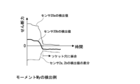
- 5 is a diagram showing an example of a change over time in a detection value of the sensor unit.
- FIG. 5 is a diagram showing an example of a shear force distribution detected by the sensor unit.
- FIG. 10 is a flowchart showing another processing procedure for executing the operation of the robot device.
- 5A to 5C are schematic side views illustrating a procedure for fitting a workpiece into a socket hole by the robot device.
- 17 is a flowchart showing an example of a processing procedure for executing the operation of the robot device shown in FIG. 16 .
- 10A to 10C are schematic side views illustrating another procedure for fitting a workpiece into a socket hole by the robot device.
- 20 is a flowchart showing an example of a processing procedure for executing the operation of the robot device shown in FIG. 18 .
- 5A to 5C are schematic side views illustrating a procedure for fitting a workpiece into a socket hole by the robot device.
- FIG. 11 is a schematic plan view of a main part for explaining another action of the robot device.
- 13 is a schematic side view of a main part illustrating another action of the robot device.
- FIG. 11 is a schematic plan view of a main part for explaining another action of the
- FIG. 1 is a perspective view of a main part of a robot device 10 according to an embodiment of the present technology.
- the robot device 10 constitutes a robot hand.
- the configuration of the robot device 10 is described below in brief.
- the robot device 10 has an arm unit 1 , a wrist unit 2 , and a hand unit 3 .
- the arm unit 1 has multiple joints 1a, and the hand unit 3 can be moved to any position by driving the joints 1a.
- the wrist unit 2 is rotatably connected to the arm unit 1, and the hand unit 3 can be rotated by the rotation of the wrist unit 2.
- the hand unit 3 has multiple fingers capable of gripping an object to be gripped (a workpiece).
- the hand unit 3 has two fingers 3a and 3b that face each other, and the workpiece can be gripped between the two fingers 3a and 3b by driving the two fingers 3a and 3b.
- the number of fingers can be changed as appropriate, to three, four or more.
- Sensor units 20a, 20b are provided on the opposing surfaces of the two finger portions 3a, 3b, respectively.
- the sensor units 20a, 20b have pressure detection surfaces and are configured to be capable of detecting pressure components applied perpendicularly to the pressure detection surfaces and their in-plane distribution.
- the sensor units 20a, 20b may be triaxial sensors capable of detecting not only pressure distribution but also shear forces parallel to the pressure detection surfaces and their in-plane distribution.
- the sensor units 20a, 20b are provided on all finger portions 3a, 3b, but the sensor units may be provided on only one of the finger portions. The configuration of the sensor units 20a, 20b will be described later with reference to FIG. 2, etc.
- the robot device 10 is driven under the control of the controller 11.
- the controller 11 includes a control unit, a memory unit, etc.
- the control unit is, for example, a CPU (Central Processing Unit), and controls the driving of each part of the robot device 10 based on a program stored in the memory unit.
- the controller 11 may be a dedicated device for the robot device 10, or may be a general-purpose device.
- the controller 11 may be, for example, a PC (Personal Computer) connected to the robot device 10 by wire or wirelessly, or a server device on a network.
- the controller 11 may be configured as a part of the robot device 10.
- the sensor units 20a and 20b have the same configuration. As described above, the sensor units 20a and 20b are each formed of a sensor sheet capable of detecting a pressure distribution on a pressure detection surface.
- Fig. 2 is a schematic side cross-sectional view showing a cross-sectional structure of a sensor sheet 210 which is one configuration example of the sensor units 20a and 20b.
- Fig. 3 is a schematic plan view showing a sensor electrode layer 30 in the sensor sheet 210.
- the x-axis direction and y-axis direction are parallel to the pressure detection surface S of the sensor sheet 210 (hereinafter also referred to as the in-plane direction), and the z-axis direction is perpendicular to the pressure detection surface S (hereinafter also referred to as the vertical direction).
- the upper side corresponds to the front side to which an external force is applied
- the lower side corresponds to the opposite back side.
- the sensor sheet 210 has an overall rectangular, flat plate shape in a planar view.
- the shape of the sensor sheet 210 in a planar view may be set appropriately according to the shape of the locations where the sensor units 20a and 20b are arranged, and there are no particular limitations on the shape of the sensor sheet 210 in a planar view.
- the shape of the sensor sheet 210 in a planar view may be a polygon other than a square, a circle, an ellipse, etc.
- the sensor sheet 210 is composed of a laminate having a pressure sensor 21, a surface layer 22 arranged on the upper surface of the pressure sensor 21, and a support layer 24 arranged on the lower surface of the pressure sensor 21.
- the pressure sensor 21 has a sensor electrode layer 30, a reference electrode layer 25, and a deformation layer 27 disposed between the sensor electrode layer 30 and the reference electrode layer 25.
- the sensor electrode layer 30 is composed of a flexible printed circuit board or the like. As shown in FIG. 3, the sensor electrode layer 30 has a main body portion 36 that is rectangular in plan view, and an extraction portion 37 that extends outward from the main body portion 36. Note that the shape of the sensor electrode layer 30 in plan view is not limited to a rectangular shape, and can be changed as appropriate.
- the sensor electrode layer 30 has a flexible substrate 29 and a plurality of sensing sections 28 provided on the surface of the substrate 29 or inside the substrate 29.
- materials that can be used for the substrate 29 include polymeric resins such as polyethylene terephthalate, polyimide, polycarbonate, and acrylic resin.
- the sensing sections 28 are regularly arranged in a matrix at predetermined intervals vertically and horizontally (vertical: y-axis direction, horizontal: x-axis direction). In the example shown in FIG. 3, the number of sensing sections 28 is 9 x 9 (vertical x horizontal), making a total of 81. The number of sensing sections 28 can be changed as appropriate.
- the sensing unit 28 is composed of a plurality of capacitance elements (detection elements) capable of detecting a change in distance from the reference electrode layer 25 as a change in capacitance.
- the sensing unit 28 includes a comb-shaped pulse electrode 281 and a comb-shaped sense electrode 282, as shown in FIG. 4, for example.
- the comb-shaped pulse electrode 281 and the comb-shaped sense electrode 282 are arranged so that their teeth face each other, and each sensing unit 28 is composed of an area (node area) in which one comb tooth is inserted between the other comb tooth.
- Each pulse electrode 281 is connected to a wiring portion 281a extending in the y-axis direction, and each sense electrode 281 is connected to a wiring portion 282a extending in the x-axis direction.
- the wiring portion 281a is arranged in the x-axis direction on the front surface of the substrate 29, and the wiring portion 282a is arranged in the y-axis direction on the back surface of the substrate 29.
- Each sense electrode 282 is electrically connected to the wiring portion 282a via a through hole 283 provided in the substrate 29.
- the sensor electrode layer 30 may have a ground line. The ground line is provided, for example, on the outer periphery of the sensor electrode layer 30 or in a portion where the wiring portions 281a and 282a run parallel to each other.
- the structure of the sensing unit 28 is not limited to the above example, and any structure may be used.
- the sensor electrode layer 30 may be formed of a laminate of a first electrode sheet having a lattice-shaped first electrode pattern extending in the x-axis direction, and a second electrode sheet having a lattice-shaped second electrode pattern extending in the y-axis direction.
- the sensing unit 28 is formed at the intersection of the first electrode pattern and the second electrode pattern.
- the reference electrode layer 25 is connected to a reference potential.
- the reference electrode layer 25 is a so-called ground electrode, and is connected to the ground potential.
- the reference electrode layer 25 is flexible, and its thickness is, for example, about 0.05 mm to 0.5 mm.
- the material for the reference electrode layer 25 may be, for example, an inorganic conductive material, an organic conductive material, or a conductive material containing both an inorganic conductive material and an organic conductive material.
- inorganic conductive materials include metals such as aluminum, copper, and silver, alloys such as stainless steel, and metal oxides such as zinc oxide and indium oxide.
- organic conductive materials include carbon materials such as carbon black and carbon fiber, and conductive polymers such as substituted or unsubstituted polyaniline and polypyrrole.
- the reference electrode layer 25 may be made of a thin metal plate such as stainless steel or aluminum, conductive fiber, or conductive nonwoven fabric.
- the reference electrode layer 25 may be formed on a plastic film by a method such as vapor deposition, sputtering, adhesion, or coating.
- the deformation layer 27 is disposed between the sensor electrode layer 30 and the reference electrode layer 25.
- the deformation layer 27 has a thickness of, for example, about 100 ⁇ m to 1000 ⁇ m.
- the deformation layer 27 is configured to be elastically deformable in response to an external force.
- an external force is applied to the sensor sheet 210 in a direction perpendicular to the sensor sheet 210
- the deformation layer 27 elastically deforms in response to the external force while the reference electrode layer 25 approaches the sensor electrode layer 30.
- the capacitance between the pulse electrode 281 and the sense electrode 282 in the sensing unit 28 changes, and the sensing unit 28 can detect this change in capacitance as a pressure value.
- the thickness of the deformation layer 27 is, for example, greater than 100 ⁇ m and equal to or less than 1000 ⁇ m, and the basis weight of the deformation layer 27 is, for example, equal to or less than 50 mg/cm 2. By setting the thickness and basis weight of the deformation layer 27 within this range, the detection sensitivity of the pressure sensor 22 in the vertical direction can be improved.
- the lower limit of the thickness of the deformation layer 27 is not particularly limited as long as it is greater than 100 ⁇ m, but this lower limit may be, for example, 150 ⁇ m or more, 200 ⁇ m or more, 250 ⁇ m or more, 300 ⁇ m or more, etc.
- the upper limit of the thickness of the deformation layer 27 is not particularly limited as long as it is 1000 ⁇ m or less, but this upper limit may be, for example, 950 ⁇ m or more, 900 ⁇ m or less, 850 ⁇ m or less, 800 ⁇ m or less, etc.
- the deformation layer 27 may be configured with a patterning structure including, for example, a columnar structure to facilitate deformation in the z-axis direction.
- This patterning structure can be a matrix, stripe, mesh, radial, geometric, spiral, or other structure.
- the surface layer 22 is made of any material, such as a flexible plastic film, woven fabric, nonwoven fabric, rubber, leather, etc.
- the surface layer 22 may be configured as a contact surface that comes into contact with the workpiece when the robot device 10 grasps the workpiece with the fingers 3a, 3b.
- the surface layer 22 functions as a pressure detection surface that receives the load (reaction force to the gripping force) from the workpiece during the gripping operation, it is preferable that the surface layer 22 has surface properties that can obtain a predetermined or greater friction force between the surface layer 22 and the workpiece in order to stably grasp the workpiece.
- the support layer 24 supports the pressure sensor 21 and functions, for example, as a bonding layer that fixes it to the surfaces of the finger portions 3a and 3b.
- the support layer 24 is composed of an adhesive layer such as a double-sided tape.
- the pull-out portion 37 of the sensor electrode layer 30 is equipped with a control unit 70 that calculates an in-plane force based on pressure information detected by the pressure sensor 21.
- the control unit 70 is typically a computer including a CPU (Central Processing Unit) and is composed of integrated circuits such as IC chips.
- the control unit 70 is mounted on the sensor electrode layer 30 (pull-out portion 37) and is configured to drive the pressure sensor 21 and to receive an output signal from the pressure sensor 21. Note that the control unit 70 is not limited to being mounted on the sensor electrode layer 30.
- (Configuration Example 2) 5 is a schematic side cross-sectional view showing a cross-sectional structure of a sensor sheet 220, which is another configuration example of the sensor units 20a and 20b. Note that the same reference numerals are used to designate parts corresponding to those in the first configuration example, and detailed descriptions thereof will be omitted.
- the sensor sheet 220 has a first pressure sensor 21a on the front side (work side), a second pressure sensor 21b on the back side (finger portions 3a, 3b side), and a separation layer 23 arranged between the first pressure sensor 21a and the second pressure sensor 21b.
- the sensor sheet 220 has a structure in which the second pressure sensor 21b, the separation layer 23, and the first pressure sensor 21a are stacked vertically from the bottom up.
- the first pressure sensor 21a and the second pressure sensor 21b have the same or nearly the same configuration as the pressure sensor 21 described above, so their description will be omitted.
- the sensor sheet 220 further includes a viscoelastic layer 81 disposed on the upper side (surface side) of the first pressure sensor 21a.
- the viscoelastic layer 81 is made of a material that is deformable in response to an external force, such as silicone gel, urethane gel, synthetic rubber, or foam.
- the viscoelastic layer 81 may be omitted if necessary.
- the sensor sheet 220 detects a force (shear force Fs) applied to the sensor sheet 220 in the in-plane direction based on the pressure center position (pressure detection position) in the in-plane direction by the first pressure sensor 21a and the pressure center position (pressure detection position) in the in-plane direction by the second pressure sensor 21b.
- the sensor sheet 220 also detects a force (load Fz) applied vertically from above the sensor sheet 220 based on the pressure value detected by the first pressure sensor 21a.
- the separation layer 23 is fixed between the first pressure sensor 21a and the second pressure sensor 21b via an adhesive layer (not shown).
- the separation layer 23 is made of a viscoelastic material that deforms due to a load applied to the first pressure sensor 21a via the surface layer 22 and the viscoelastic layer 81. Examples of this type of viscoelastic material include silicone gel, urethane gel, synthetic rubber, and foam.
- the thickness of the separation layer 23 is not particularly limited and is, for example, 1000 ⁇ m or more and 5000 ⁇ m or less, and is set according to the thickness of the viscoelastic layer 81, etc.
- the planar shape of the separation layer 23 is not particularly limited and is typically rectangular or circular.
- FIG. 6 is a block diagram showing an example of a control system of the robot device 10.
- the robot device 10 has a controller 11 and a drive section 12 that drives the arm section 1, hand section 3, etc.
- the drive section 12 includes a drive unit 12a that drives the finger sections 3a and 3b.
- the controller 11 is configured to be capable of executing a control program for operating the robot device 10 based on input signals from various sensors.
- the sensor units 20a and 20b constitute one of the various sensors described above, and are attached to the gripping surface of the hand unit 3 for gripping the workpiece. Based on a control command from the controller 11, the sensor units 20a and 20b output a gripping command to the drive unit 12a, which drives the fingers 3a and 3b of the hand unit 3, to grip the workpiece.
- the sensor units 20a and 20b detect the pressing force (pressure distribution, gripping force (vertical load) or shear force) acting on the pressure detection surface S, and the control unit 70 calculates the value of the pressing force and inputs it to the controller 11.
- the controller 11 generates various control commands (drive signals) for controlling the position and posture of the arm unit 1 and the hand unit 3 (fingers 3a and 3b), and outputs them to the drive unit 12.
- the drive unit 12 is typically an actuator such as an electric motor or a fluid pressure cylinder, and drives the arm unit 1, the hand unit 3, etc., based on the drive signal from the controller 11.
- the controller 11 includes a control unit 111 and a memory unit 112.
- the control unit 111 is, for example, a CPU (Central Processing Unit), and controls the driving of each part of the arm unit 1 and the hand unit 3 by executing a program stored in the memory unit 112 based on a sensor signal from the control unit 70.
- the control unit 70 acquires force information in three axial directions detected by the sensor sheet 210 (220), and outputs this information to the controller 11 as a sensor signal.
- the controller 11 controls the driving of the arm unit 1 and the hand unit 3 so that the object is stably grasped with an appropriate gripping force, and the position and posture of the hand unit 3 are set to a predetermined position and posture described below.
- controller 11 and the control unit 70 are configured as a control device that detects the stress distribution and shear force acting on the gripping surface (pressure detection surface S) based on the output of the sensor sheet 210 (220) and generates control commands to change the position and posture of the hand unit 3.
- the storage unit 112 includes a non-volatile memory that stores various programs and data necessary for the processing of the control unit 111, and a volatile memory that is used as a working area for the control unit 111.
- the various programs may be read from a portable recording medium such as a semiconductor memory, or may be downloaded from a server device on a network.
- the control unit 70 is electrically connected to the sensor sheet 210 (220) and is configured to calculate the pressure acting on each finger portion 3a, 3b and its in-plane distribution based on the output of the sensor sheet 210 (220).
- the control unit 70 is further electrically connected to the controller 11 and outputs the calculated pressure and its in-plane distribution to the controller 11, and outputs a gripping command to the drive unit 12a that drives the fingers 3a, 3b of the hand portion 3 based on a control command from the controller 11.
- the controller 11 and the control unit 70 are configured as a control device that controls the operation of the hand portion 3.
- the gripping command that is supplied to the drive unit 12a that drives the finger portions 3a and 3b is generated by the control unit 70, but instead, the controller 11 that controls the overall operation of the robot device 10 may generate the gripping command.
- the controller 11 is configured as the above-mentioned control device.
- Fig. 7 is a side view explaining the operation of the robot device 10, and Fig. 8 is a plan view thereof.
- the X-axis, Y-axis, and Z-axis indicate three mutually orthogonal axial directions in real space, where the X-axis direction is the front-rear direction, the Y-axis direction is the left-right direction, and the Z-axis direction is the height direction.
- the robot device 10 of this embodiment is configured as an assembly robot that fits a workpiece W into a fitting hole (hereinafter, socket hole 92) of a socket 90 supported by a support portion 88.
- the workpiece W is a connector part that includes a main body Wa and a terminal Wb.
- the main body Wa is, for example, a rectangular resin member with a length direction in the X-axis direction, a width direction in the Y-axis direction, and a thickness direction in the Z-axis direction
- the terminal Wb is a similarly rectangular metal member that protrudes in the X-axis direction from the tip of the main body Wa.
- the socket 90 has an opening surface (opening end) 91 where the socket hole 92 opens, and is supported by the support part 88 so that the opening surface 91 is perpendicular to the X-axis direction.
- the support part 88 may be a part of a device equipped with the socket 90, or may be another robot hand that holds the socket 90.
- the socket hole 92 has an opening shape that corresponds to the outer shape of the terminal part Wb, and the depth of the socket hole 92 is not particularly limited and may be formed to a size that corresponds to the length of the terminal part Wb.
- the terminal part Wb fits into the socket hole 92, thereby mechanically and electrically connecting the workpiece W to the socket 90.
- the controller 11 positions the workpiece W and the socket 90 facing each other at a predetermined distance in the X-axis direction, and then moves the hand unit 3 holding the workpiece W in parallel in the X-axis direction to fit the terminal portion Wb of the workpiece W into the socket hole 92.
- the position of the hand unit 3 is adjusted based on preset coordinate values in the XYZ space.
- a camera may be installed on the hand unit 3 and the position of the hand unit 3 may be adjusted based on image information from the camera.
- the controller 11 executes the following control.
- FIG. 9 is a schematic side view for explaining a procedure for positioning the workpiece W at the fitting position by the robot device 10
- Fig. 10 is a flowchart showing an example of a processing procedure of the controller 11 for executing the operation of the robot device 10 shown in Fig. 9.
- Figs. 9A and 9B show a state in which the terminal portion Wb of the workpiece W abuts against the opening surface 91 of the socket 90 at a position slightly shifted upward (in the +Z direction) from the fitting position with the socket hole 92.
- Y-axis direction left-right direction
- the controller 11 generates a movement command to move the arm 1 (synonymous with the hand 3; the same applies below) in parallel in the +X direction from the position shown in FIG. 7 where the hand 3 faces the socket 90, thereby moving the hand 3 closer to the socket 90 (ST101).
- the controller 11 determines whether the terminal Wb of the workpiece W abuts against the opening surface 91 of the socket 90 (ST102).
- the determination of whether the terminal Wb abuts against the opening surface 91 is made based on whether the scalar value of the shear vector acting on the sensor units 20a and 20b when the terminal Wb abuts against the opening surface 91 exceeds a predetermined threshold value, and when the scalar value exceeds the threshold value, it is determined that the terminal Wb abuts against the opening surface 91.
- the controller 11 determines that the terminal Wb abuts against the opening surface 91 (Yes in ST102), it stops the movement of the arm 1 (ST103).
- the stress distribution (shear force) of the sensor units 20a and 20b differs from each other.
- an increase in stress is detected in the front region closer to the terminal unit Wb than the center position of the pressure detection surface S
- an increase in stress is detected in the rear region farther from the terminal unit Wb than the center position of the pressure detection surface S.
- the magnitude of the shear force detected by the sensor units 20a and 20b differs depending on the direction of the moment My. Therefore, the direction of the moment My can be determined by calculating the difference between the detection values of the sensor units 20a and 20b.
- Figure 13 shows an example of the change over time in the detection values of the sensor units 20a and 20b.
- the controller 11 generates a control command (first control command) to correct the position of the hand unit 3 to a position where the workpiece W is aligned with the socket 90 in the X-axis direction based on the direction of the moment My determined based on the output of the sensors 20a and 20b as described above.
- the controller 11 determines whether the moment My is downward in FIG. 9B (ST104), and if it is determined that it is downward, generates a movement command to translate the arm unit 1 downward (-Z direction) (ST105). Conversely, if it is determined that the moment My is upward, generates a movement command to translate the arm unit 1 upward (+Z direction) (ST106). The vertical translation of the arm unit 1 continues until the terminal portion Wb of the workpiece W fits into the socket hole 92.
- the controller 11 determines whether the terminal portion Wb of the workpiece W is engaged with the socket hole 92 (ST107).
- the scalar value of the shear force detected by the sensor units 20a and 20b becomes equal to or less than the predetermined threshold value (see FIG. 13).
- the controller 11 then continues the parallel movement of the arm unit 1 until the scalar value becomes equal to or less than the threshold value, and stops the parallel movement of the arm unit 1 when it is determined that the scalar value has become equal to or less than the threshold value (ST108). This allows the workpiece W to be positioned with high precision so that it is aligned with the socket 90 in the X-axis direction.
- FIG. 11 is a schematic plan view illustrating another procedure for positioning the workpiece W at the fitting position by the robot device 10
- FIG. 12 is a flowchart showing an example of a processing procedure of the controller 11 that executes the operation of the robot device 10 shown in FIG. 11.
- FIGS. 11A and 11B are schematic plan views showing a state in which the terminal portion Wb of the workpiece W abuts against the opening surface 91 of the socket 90 at a position slightly shifted to the left (-Y direction) from the fitting position with the socket hole 92.
- the controller 11 generates a movement command to move the arm 1 in parallel in the +X direction from the position shown in FIG. 7 where the hand unit 3 faces the socket 90, thereby moving the hand unit 3 closer to the socket 90 (ST201).
- the controller 11 determines whether the terminal Wb of the workpiece W has come into contact with the opening surface 91 of the socket 90 (ST202), and when it determines that the terminal Wb has come into contact with the opening surface 91, stops the movement of the arm 1 (ST203).
- the direction of moment Mz may be determined by taking the difference between the shear force in the front region and the shear force in the rear region of sensor units 20a and 20b. In determining moment Mz, the output of either sensor 20a or 20b may be referenced, or the average or maximum value of both outputs may be referenced.
- the controller 11 generates a control command (first control command) to correct the position of the hand unit 3 to a position where the workpiece W is aligned with the socket 90 in the X-axis direction based on the direction of the moment Mz determined based on the output of the sensors 20a and 20b as described above.
- the controller 11 determines whether the moment Mz faces to the right (downward in FIG. 11B) (ST204), and if it determines that it faces to the right, generates a movement command to translate the arm unit 1 to the right (+Y direction) (ST205). Conversely, if it determines that the moment Mz faces to the left, it generates a movement command to translate the arm unit 1 to the left (-Y direction) (ST206). The left-right translation of the arm unit 1 continues until the terminal portion Wb of the workpiece W fits into the socket hole 92.
- the controller 11 determines whether the terminal portion Wb of the workpiece W is engaged with the socket hole 92 (ST207).
- the scalar value of the shear force detected by the sensor units 20a and 20b becomes equal to or less than the predetermined threshold value.
- the controller 11 then continues the parallel movement of the arm unit 1 until the scalar value becomes equal to or less than the threshold value, and stops the parallel movement of the arm unit 1 when it is determined that the scalar value has become equal to or less than the threshold value (ST208). This allows the workpiece W to be positioned with high precision so that it is aligned with the socket 90 in the X-axis direction.
- FIG. 15 is a flow chart showing an example of a processing procedure that integrates the above-mentioned vertical and horizontal positioning control.
- a procedure is described for determining the directions of the moments My and Mz acting on the workpiece W individually, and correcting the relative position of the workpiece W with respect to the socket hole 92 while adjusting the movement direction of the arm unit 1 according to the determination result.
- the controller 11 generates a movement command to move the arm 1 in parallel in the +X direction from the position shown in FIG. 7 where the hand unit 3 faces the socket 90, thereby moving the hand unit 3 closer to the socket 90 (ST301).
- the controller 11 determines whether the terminal Wb of the workpiece W has come into contact with the opening surface 91 of the socket 90 (ST302), and when it determines that the terminal Wb has come into contact with the opening surface 91, stops the movement of the arm 1 (ST303).
- the controller 11 determines whether the moment My acting on the workpiece W is directed downward (ST303), and if it determines that the moment My is directed downward, moves the arm unit 1 in parallel downward (-Z direction) (ST304). If the moment My acting on the workpiece W is directed upward, the controller 11 moves the arm unit 1 in parallel upward (+Z direction) (ST303, 304).
- the controller 11 determines whether the moment Mz is oriented to the right (ST307). If the controller 11 determines that the moment Mz is oriented to the right, it translates the arm unit 1 to the right (+Y direction) (ST308), and if it determines that the moment Mz is oriented to the left, it translates the arm unit 1 to the left (-Y direction) (ST309, 310).
- the arm unit 1 continues to move in a vertical or horizontal parallel direction until the terminal portion Wb of the workpiece W fits into the socket hole 92.
- the movement of the arm unit 1 is stopped (ST311, 312). This allows the workpiece W to be positioned with high precision so that it is aligned with the socket 90 in the X-axis direction.
- FIG. 16 is a schematic side view illustrating the procedure for fitting the workpiece W into the socket hole 92 by the robot device 10
- FIG. 17 is a flowchart showing an example of the processing procedure of the controller 11 that executes the operation of the robot device 10 shown in FIG. 16.
- FIGS. 16A and 16B show the state in which the terminal portion Wb is fitted into the socket hole 92 with the axis of the workpiece W tilted slightly downward around the Y axis relative to the axis of the socket hole 92.
- the controller 11 generates a movement command to move the arm portion 1 in parallel in the +X direction from the state shown in FIG. 16A, thereby starting to fit the terminal portion Wb of the workpiece W into the socket hole 92 (ST401).
- the controller 11 determines the presence and direction of a moment acting on the workpiece W based on the detection values of the sensor units 20a and 20b even while the terminal unit Wb is being fitted into the socket hole 92. That is, the controller 11 further determines the direction of the moment acting on the workpiece W based on the output of the sensor units 20a and 20b when the workpiece W is moved in the X-axis direction inside the socket 90, and generates a control command (second control command) to correct the attitude of the hand unit 3 based on the determined direction of the moment.
- a control command second control command
- a moment My acts on the workpiece W about the Y axis.
- the controller 11 detects this moment My and determines whether its direction is upward (ST402).
- the controller 11 generates a control command to rotate the arm unit 1 in the same direction as the moment My, that is, upward (- ⁇ side), around the tip of the terminal portion Wb of the workpiece W, while moving the arm unit 1 in the +X direction (ST403).
- This allows the hand unit 3 to rotate in a direction in which the axis of the workpiece W coincides with the axis of the socket hole 92, as shown in FIG. 16B.
- the upward rotational movement of the arm unit 1 continues until the magnitude of the moment My becomes equal to or less than a predetermined value.
- the controller 11 when the direction of the moment My is determined to be downward, the controller 11 generates a control command to move the arm portion 1 in the +X direction while rotating it downward (to the + ⁇ side), which is the same direction as the moment My, around the tip of the terminal portion Wb of the workpiece W (ST404).
- the controller 11 determines whether the fitting of the workpiece W into the socket hole 92 has been completed (ST405).
- the determination of whether the fitting of the workpiece W into the socket hole 92 has been completed is made based on whether the scalar value of the shear vector acting on the sensor units 20a and 20b exceeds the above-mentioned predetermined threshold value.
- the controller 11 determines that the fitting of the workpiece W into the socket hole 92 has been completed (Yes in ST405), it stops the parallel movement of the arm unit 1 in the +X direction (ST406).
- Fig. 18 is a schematic side view illustrating another procedure for fitting the workpiece W into the socket hole 92 by the robot device 10
- Fig. 19 is a flowchart showing an example of a processing procedure of the controller 11 that executes the operation of the robot device 10 shown in Fig. 18.
- Figs. 18A and 18B show the state in which the terminal portion Wb is fitted into the socket hole 92 with the axis of the workpiece W tilted slightly to the right around the Z axis with respect to the axis of the socket hole 92.
- the controller 11 generates a movement command to move the arm portion 1 in parallel in the +X direction from the state shown in FIG. 18A, thereby starting to fit the terminal portion Wb of the workpiece W into the socket hole 92 (ST501).
- a moment Mz (prying) about the Z axis acts on the workpiece W.
- the controller 11 detects this moment Mz and determines whether its direction is to the left (ST502).
- the controller 11 generates a control command to rotate the workpiece W to the left (- ⁇ side), which is the same direction as the moment Mz, around the tip of the terminal portion Wb of the workpiece W while moving the arm unit 1 in the +X direction (ST503).
- This allows the hand unit 3 to rotate in a direction in which the axis of the workpiece W coincides with the axis of the socket hole 92, as shown in FIG. 18B.
- the arm unit 1 continues to rotate to the left until the magnitude of the moment Mz becomes equal to or less than a predetermined value.
- the controller 11 when the direction of moment Mz is determined to be to the right, the controller 11 generates a control command to move the arm portion 1 in the +X direction while rotating it to the right (+ ⁇ side), which is the same direction as moment Mz, around the tip of the terminal portion Wb of the workpiece W (ST504).
- the controller 11 determines whether or not the fitting operation of the workpiece W into the socket hole 92 is complete (ST505).
- the controller 11 determines that the fitting operation of the workpiece W into the socket hole 92 is complete (Yes in ST505), it stops the parallel movement of the arm unit 1 in the +X direction (ST506).
- FIG. 20 is a flow chart showing an example of a processing procedure that integrates the above-mentioned vertical and horizontal fitting posture control.
- a procedure is described in which the directions of the moments My and Mz acting on the workpiece W are determined individually, and the posture of the workpiece W relative to the socket hole 92 is corrected while adjusting the rotation direction of the arm unit 1 according to the determination result.
- the controller 11 generates a movement command to move the arm portion 1 parallel to the +X direction from the fitting start position of the workpiece W into the socket hole 92, thereby starting fitting the terminal portion Wb of the workpiece W into the socket hole 92 (ST601).
- the controller 11 determines whether the moment My acting on the workpiece W is directed upward (ST602).
- the controller 11 When the moment My is directed upward, the controller 11 generates a control command to rotate the arm unit 1 around the tip of the terminal portion Wb of the workpiece W in the same direction as the moment My, upward (- ⁇ side), while moving the arm unit 1 in the +X direction (ST603).
- the controller 11 When the moment My acting on the workpiece W is directed downward, the controller 11 generates a control command to rotate the arm unit 1 around the tip of the terminal portion Wb of the workpiece W in the same direction as the moment My, downward (+ ⁇ side), while moving the arm unit 1 in the +X direction (ST604, 605).
- the controller 11 determines whether the moment Mz is directed to the left (ST606). If the moment Mz is directed to the left, the controller 11 generates a control command to rotate the arm unit 1 around the tip of the terminal portion Wb of the workpiece W to the left (- ⁇ side), which is the same direction as the moment Mz, while moving the arm unit 1 in the +X direction (ST607).
- the controller 11 If the moment Mz acting on the workpiece W is directed to the right, the controller 11 generates a control command to rotate the arm unit 1 around the tip of the terminal portion Wb of the workpiece W to the right (+ ⁇ side), which is the same direction as the moment Mz, while moving the arm unit 1 in the +X direction (ST608, 609).
- the controller 11 determines whether the fitting of the workpiece W into the socket hole 92 has been completed (ST610). When the fitting of the workpiece W into the socket hole 92 has been completed (Yes in ST102), the controller 11 stops the parallel movement of the arm unit 1 in the +X direction (ST611). This allows the workpiece W to be properly fitted into the socket 90 while preventing the workpiece W from being twisted in the socket hole 92, thereby preventing damage to the workpiece W or the socket 90 due to the twisting.
- the magnitude and direction of the moment acting on the workpiece W is determined based on the pressure distribution detected by the sensors 20a, 20b provided on the gripping surface of the hand unit 3, and the position and posture of the hand unit 3 relative to the socket hole 92 are corrected based on the determination result.
- This makes it possible to eliminate the effects of noise due to the vibration and inertia of the robot itself and ensures highly accurate and appropriate fitting work, compared to a configuration in which a force sensor or the like is placed on the wrist portion of the hand.
- it is no longer necessary to position the workpiece W relative to the socket hole 92 using a camera image it is possible to prevent a decrease in work tact time and to prevent an increase in equipment costs and adjustment costs.
- the fitting operation of the workpiece W into the socket hole 92 has been mainly described, but according to the robot device 10 of this embodiment, the workpiece to be grasped may be a bottle cap.
- the rotation torque of the cap W2 can be detected based on the shear force acting on the sensor units 20a and 20b when the cap W2 rotates in association with the opening and closing operation of the bottle.
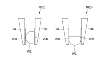
- the robot device 10 can also detect the gripping posture of the workpiece W2, which has shape anisotropy. If the workpiece W2 has a partial spherical shape with a flat surface in one area, it can determine, based on the stress distribution detected by the sensors 20a and 20b, whether the gripping posture is a first posture in which the flat surface is vertical, as shown on the left side of the figure, or a second posture in which the flat surface is horizontal, as shown on the right side of the figure.
- a capacitance change type detection element is used to detect the pressure distribution, but this is not limited to this, and for example, a resistance change type detection element whose resistance value changes depending on the magnitude of pressure may be used.
- the directions of the moments My and Mz detected when the terminal portion Wb of the workpiece W presses against the opening surface 91 of the socket 90 in the X-axis direction are determined (ST104, 204).
- the terminal portion Wb may be aligned with the socket hole 92 by moving the arm portion 1 in the oblique direction.
- a robot device that fits a workpiece into a socket having an opening surface perpendicular to a first axial direction, a hand unit including a plurality of fingers each having a gripping surface capable of gripping the workpiece in a second axial direction perpendicular to the first axial direction;
- a sensor unit provided on at least one of the plurality of finger portions and capable of detecting a pressure distribution on the grip surface;
- a control device configured to determine a direction of a moment acting on the workpiece based on an output of the sensor unit when the workpiece is pressed against the opening surface in the first axial direction, and to generate a first control command to correct a position of the hand unit to a position where the workpiece is aligned with the socket in the first axial direction based on the determined direction of the moment.
- the robot device determines a direction of a moment about a second axis perpendicular to the gripping surface, and generates, based on the determined direction of the moment, a control command to translate the hand unit in a third axis direction parallel to the gripping surface and perpendicular to the first axis and the second axis, as the first control command.
- the sensor unit is provided on each of the plurality of finger portions, The control device determines a direction of a moment about the third axis, and generates, as the first control command, a control command for moving the hand unit parallel to the second axis direction based on the determined direction of the moment.
- the robot device further determines a direction of a moment acting on the workpiece based on an output of the sensor unit when the workpiece is moved in the first axial direction inside the socket, and generates a second control command to correct the posture of the hand unit based on the determined direction of the moment.
- a direction of a moment about a second axis perpendicular to the gripping surface is determined, and a control command is generated as the second control command to rotate the hand unit about the second axis with the tip of the work as the center in the same direction as the determined direction of the moment.
- the robot device is provided on each of the plurality of finger portions, The control device determines an orientation around a third axis parallel to the gripping surface and perpendicular to the first axis and the second axis, and generates, as the second control command, a control command for rotating the hand unit around the third axis around the tip of the workpiece in the same direction as the determined orientation of the moment.
- the robot device is configured with an elastically deformable sensor sheet having a plurality of capacitance elements that detects pressure acting on the gripping surface.
- the sensor sheet is a pressure sensor having a sensor electrode layer in which the plurality of capacitance elements are arranged in a matrix, a reference electrode layer connected to a reference potential, and a deformation layer disposed between the sensor electrode layer and the reference electrode layer.
- the sensor sheet includes: a pair of pressure sensors each including a sensor electrode layer in which the plurality of capacitance elements are arranged in a matrix, a reference electrode layer connected to a reference potential, and a deformation layer disposed between the sensor electrode layer and the reference electrode layer; a separation layer made of a viscoelastic material and disposed between the pair of pressure sensors.
- a method for controlling a robot device including a hand unit including a plurality of fingers each having a gripping surface capable of gripping a workpiece in a second axial direction perpendicular to a first axial direction, and a sensor unit provided on at least one of the plurality of fingers and capable of detecting a pressure distribution on the gripping surface, the method including fitting a workpiece into a socket having an opening surface perpendicular to the first axial direction, the method comprising: determining a direction of a moment acting on the workpiece based on an output of the sensor unit when the workpiece is pressed against the opening surface in the first axial direction; generating a control command for moving the hand unit to a position where the workpiece is aligned with the socket in the first axial direction based on the determined direction of the moment.
Landscapes
- Engineering & Computer Science (AREA)
- Robotics (AREA)
- Mechanical Engineering (AREA)
- Human Computer Interaction (AREA)
- Manipulator (AREA)
Priority Applications (2)
| Application Number | Priority Date | Filing Date | Title |
|---|---|---|---|
| CN202480026311.7A CN120981325A (zh) | 2023-04-25 | 2024-03-18 | 机器人设备及其控制方法 |
| JP2025516599A JPWO2024224877A1 (https=) | 2023-04-25 | 2024-03-18 |
Applications Claiming Priority (2)
| Application Number | Priority Date | Filing Date | Title |
|---|---|---|---|
| JP2023-071464 | 2023-04-25 | ||
| JP2023071464 | 2023-04-25 |
Publications (1)
| Publication Number | Publication Date |
|---|---|
| WO2024224877A1 true WO2024224877A1 (ja) | 2024-10-31 |
Family
ID=93256161
Family Applications (1)
| Application Number | Title | Priority Date | Filing Date |
|---|---|---|---|
| PCT/JP2024/010431 Ceased WO2024224877A1 (ja) | 2023-04-25 | 2024-03-18 | ロボット装置およびその制御方法 |
Country Status (3)
| Country | Link |
|---|---|
| JP (1) | JPWO2024224877A1 (https=) |
| CN (1) | CN120981325A (https=) |
| WO (1) | WO2024224877A1 (https=) |
Citations (3)
| Publication number | Priority date | Publication date | Assignee | Title |
|---|---|---|---|---|
| JP2003127081A (ja) * | 2001-10-18 | 2003-05-08 | Ricoh Co Ltd | 組立ロボット及び当該組立ロボットによる部品組立方法 |
| JP2020049582A (ja) * | 2018-09-26 | 2020-04-02 | オムロン株式会社 | エンドエフェクタ装置 |
| WO2023047630A1 (ja) * | 2021-09-22 | 2023-03-30 | ソニーグループ株式会社 | ロボット装置およびその制御方法 |
-
2024
- 2024-03-18 JP JP2025516599A patent/JPWO2024224877A1/ja active Pending
- 2024-03-18 CN CN202480026311.7A patent/CN120981325A/zh active Pending
- 2024-03-18 WO PCT/JP2024/010431 patent/WO2024224877A1/ja not_active Ceased
Patent Citations (3)
| Publication number | Priority date | Publication date | Assignee | Title |
|---|---|---|---|---|
| JP2003127081A (ja) * | 2001-10-18 | 2003-05-08 | Ricoh Co Ltd | 組立ロボット及び当該組立ロボットによる部品組立方法 |
| JP2020049582A (ja) * | 2018-09-26 | 2020-04-02 | オムロン株式会社 | エンドエフェクタ装置 |
| WO2023047630A1 (ja) * | 2021-09-22 | 2023-03-30 | ソニーグループ株式会社 | ロボット装置およびその制御方法 |
Also Published As
| Publication number | Publication date |
|---|---|
| CN120981325A (zh) | 2025-11-18 |
| JPWO2024224877A1 (https=) | 2024-10-31 |
Similar Documents
| Publication | Publication Date | Title |
|---|---|---|
| US9869597B1 (en) | Compound strain gage carrier for multi-axis force/torque sensing | |
| US8498745B2 (en) | Robot apparatus and gripping method for use in robot apparatus | |
| US9919422B1 (en) | Methods and systems to provide mechanical feedback during movement of a robotic system | |
| JP6996113B2 (ja) | ロボット制御方法、ロボットシステムおよび制御装置 | |
| US20100312393A1 (en) | Robot with camera | |
| JP7052917B2 (ja) | ロボットハンド、ロボットハンド制御方法及びプログラム | |
| CN113654747B (zh) | 机器人的关节刚度的检测方法、装置和机器人 | |
| KR20200007004A (ko) | 핸드 기구, 파지 시스템 및 파지 프로그램 | |
| JP6988757B2 (ja) | エンドエフェクタおよびエンドエフェクタ装置 | |
| JP2009066683A (ja) | ロボットハンド及び制御方法、並びにプログラム | |
| WO2024024377A1 (en) | Sensing system for grip control, gripping apparatus, robot apparatus and control method for same | |
| US20180200893A1 (en) | Control device and robot system | |
| US20250128425A1 (en) | Robot apparatus and control method therefor | |
| JP2006035329A (ja) | 物体把持装置 | |
| CN119658667A (zh) | 驱动装置、控制方法、机器人、记录介质和产品制造方法 | |
| WO2024224877A1 (ja) | ロボット装置およびその制御方法 | |
| Ye et al. | Robust robotic grasping using IR net-structure proximity sensor to handle objects with unknown position and attitude | |
| JP2020049578A (ja) | ロボット | |
| JP2018114585A (ja) | 組立装置及び組立方法 | |
| JP5942720B2 (ja) | 状態判別方法、ロボット、制御装置、及びプログラム | |
| WO2023171126A1 (ja) | ロボット装置およびセンサ装置 | |
| WO2024089940A1 (ja) | 荷重検出器およびロボットハンド | |
| JP3439935B2 (ja) | ワーク把持装置 | |
| JP2019010721A (ja) | エンドエフェクタ | |
| JP2023073828A (ja) | ワーク取出し装置、ワーク取出し方法、プログラム及び制御装置 |
Legal Events
| Date | Code | Title | Description |
|---|---|---|---|
| 121 | Ep: the epo has been informed by wipo that ep was designated in this application |
Ref document number: 24796635 Country of ref document: EP Kind code of ref document: A1 |
|
| ENP | Entry into the national phase |
Ref document number: 2025516599 Country of ref document: JP Kind code of ref document: A |
|
| WWE | Wipo information: entry into national phase |
Ref document number: 2025516599 Country of ref document: JP |
|
| NENP | Non-entry into the national phase |
Ref country code: DE |
|
| 122 | Ep: pct application non-entry in european phase |
Ref document number: 24796635 Country of ref document: EP Kind code of ref document: A1 |