WO2024224768A1 - ドリルおよび切削加工物の製造方法 - Google Patents
ドリルおよび切削加工物の製造方法 Download PDFInfo
- Publication number
- WO2024224768A1 WO2024224768A1 PCT/JP2024/005716 JP2024005716W WO2024224768A1 WO 2024224768 A1 WO2024224768 A1 WO 2024224768A1 JP 2024005716 W JP2024005716 W JP 2024005716W WO 2024224768 A1 WO2024224768 A1 WO 2024224768A1
- Authority
- WO
- WIPO (PCT)
- Prior art keywords
- cutting edge
- drill
- flank
- outer periphery
- extending
- Prior art date
- Legal status (The legal status is an assumption and is not a legal conclusion. Google has not performed a legal analysis and makes no representation as to the accuracy of the status listed.)
- Ceased
Links
Images


Classifications
-
- B—PERFORMING OPERATIONS; TRANSPORTING
- B23—MACHINE TOOLS; METAL-WORKING NOT OTHERWISE PROVIDED FOR
- B23B—TURNING; BORING
- B23B51/00—Tools for drilling machines
- B23B51/0006—Drills with cutting inserts
- B23B51/0007—Drills with cutting inserts with exchangeable cutting insert
-
- B—PERFORMING OPERATIONS; TRANSPORTING
- B23—MACHINE TOOLS; METAL-WORKING NOT OTHERWISE PROVIDED FOR
- B23B—TURNING; BORING
- B23B51/00—Tools for drilling machines
- B23B51/02—Twist drills
-
- B—PERFORMING OPERATIONS; TRANSPORTING
- B23—MACHINE TOOLS; METAL-WORKING NOT OTHERWISE PROVIDED FOR
- B23B—TURNING; BORING
- B23B2251/00—Details of tools for drilling machines
- B23B2251/14—Configuration of the cutting part, i.e. the main cutting edges
-
- B—PERFORMING OPERATIONS; TRANSPORTING
- B23—MACHINE TOOLS; METAL-WORKING NOT OTHERWISE PROVIDED FOR
- B23B—TURNING; BORING
- B23B2251/00—Details of tools for drilling machines
- B23B2251/18—Configuration of the drill point
-
- B—PERFORMING OPERATIONS; TRANSPORTING
- B23—MACHINE TOOLS; METAL-WORKING NOT OTHERWISE PROVIDED FOR
- B23B—TURNING; BORING
- B23B2251/00—Details of tools for drilling machines
- B23B2251/20—Number of cutting edges
- B23B2251/202—Three cutting edges
-
- B—PERFORMING OPERATIONS; TRANSPORTING
- B23—MACHINE TOOLS; METAL-WORKING NOT OTHERWISE PROVIDED FOR
- B23B—TURNING; BORING
- B23B2251/00—Details of tools for drilling machines
- B23B2251/40—Flutes, i.e. chip conveying grooves
-
- B—PERFORMING OPERATIONS; TRANSPORTING
- B23—MACHINE TOOLS; METAL-WORKING NOT OTHERWISE PROVIDED FOR
- B23B—TURNING; BORING
- B23B51/00—Tools for drilling machines
- B23B51/0002—Drills with connected cutting heads, e.g. with non-exchangeable cutting heads; Drills with a single insert extending across the rotational axis and having at least two radially extending cutting edges in the working position
Definitions
- This disclosure relates to a drill used in cutting and a method for manufacturing a cut product.
- the drills described in Patent Documents 1 and 2 are known as drills used for cutting workpieces such as metal members.
- the cutting edge of a drill has a chisel edge located at the innermost side and extending from the central axis.
- the chisel edge affects the linear stability of the drill.
- the drill described in Patent Document 1 has one flank face (second flank face) as a flank face for one cutting edge.
- the drill described in Patent Document 2 has two flank faces (a first tip flank face located on the inner circumference side and a second tip flank face located on the outer circumference side) as a flank face for one cutting edge.
- a non-limiting example of a drill in the present disclosure has a rod shape rotatable around a rotation axis and a body extending from a tip to a rear end along the rotation axis.
- the body has a flank located at the tip, a cutting edge located at a front edge of the flank in the rotation direction, and an exhaust groove extending from the cutting edge.
- the flank has a flat first flank extending from the rotation axis toward the outer periphery and approaching the rear end as it approaches the outer periphery, a concavely curved second flank extending from the first flank toward the outer periphery, and a flat third flank extending from the second flank toward the outer periphery and approaching the rear end as it approaches the outer periphery.
- the cutting edge has an inner cutting edge located along the first flank, a central cutting edge located along the second flank, and an outer cutting edge located along the third flank.
- the inner cutting edge has a chisel edge extending from the rotation axis toward the outer periphery and a first cutting edge extending from the chisel edge toward the outer periphery.
- the central cutting edge has a concave curved shape
- the outer cutting edge has a second cutting edge extending toward the outer periphery and having a concave curved shape.
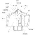
- FIG. 1 is a perspective view of a drill according to an embodiment of the present disclosure.
- FIG. 2 is a perspective view showing an insert in the drill shown in FIG. 1 .
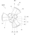
- FIG. 3 is a front view of the insert shown in FIG. 2 as viewed from the tip side.
- FIG. 4 is an enlarged view of region IV shown in FIG. 3 .
- FIG. 4 is a side view of the insert shown in FIG. 3 as viewed from the A1 direction.
- FIG. 4 is a side view of the insert shown in FIG. 3 as viewed from the A2 direction.
- 7 is a cross-sectional view taken along line VII-VII in FIG. 4.
- 8 is a cross-sectional view taken along line VIII-VIII in FIG. 4.
- FIG. 9 is a cross-sectional view taken along line IX-IX of FIG. 4.
- 5 is a cross-sectional view taken along line XX in FIG. 4.
- 10 is a cross-sectional view taken along line XI-XI of FIG. 4.
- 5 is a cross-sectional view taken along line XII-XII in FIG. 4.
- FIG. 5 is an enlarged view of the same area shown in FIG.
- FIG. 2 is a schematic diagram showing a step of a manufacturing method of a machined product according to an embodiment of the present disclosure.
- FIG. 2 is a schematic diagram showing a step of a manufacturing method of a machined product according to an embodiment of the present disclosure.
- FIG. 2 is a schematic diagram showing a step of a manufacturing method of a machined product according to an embodiment of the present disclosure.
- the drill described in Patent Document 1 has only one flat flank as a flank for one cutting edge. Therefore, there is a risk that the chisel edge will not bite into the workpiece sufficiently after the main cutting edge bites into it.
- the first tip flank extends over a wide range from the central axis toward the outer periphery. Therefore, as with the drill described in Patent Document 1, there is a risk that the chisel edge will not bite into the workpiece sufficiently after the main cutting edge bites into it.
- the purpose of this disclosure is to provide a drill whose cutting edge can effectively bite into the workpiece.
- FIG. 1 is a perspective view showing a drill according to an embodiment of the present disclosure.
- Figure 2 is a perspective view showing an insert in the drill shown in Figure 1.
- Figure 3 is a front view of the insert shown in Figure 2 as viewed from the tip side.
- the drill 1 in one embodiment of the present disclosure has a rod-shaped body 3 that is rotatable around a rotation axis O1, as shown in Figures 1 to 3.
- the body 3 extends from the tip 3a to the rear end 3b along the rotation axis O1.
- the body 3 has a gripping portion 5 called a shank that is gripped by a rotating spindle of a machine tool or the like, and a cutting portion 7 called a body that is located on the tip side of the gripping portion 5.
- the gripping portion 5 is a portion that is designed according to the shape of the spindle or the like in the machine tool.
- the cutting portion 7 is a portion that comes into contact with the workpiece and plays a major role in cutting the workpiece.
- the arrow Y1 in FIG. 1 indicates the direction of rotation of the drill 1 (main body 3).
- the cutting part 7 (main body 3) has a clearance surface 9 located at the tip 3a, a cutting edge 11 located at the front edge of the clearance surface 9 in the rotational direction Y1, and an exhaust groove 13 extending from the cutting edge 11.
- the number of clearance surfaces 9, cutting edges 11, and exhaust grooves 13 is not limited to a specific number.
- the cutting part 7 in the non-limiting example shown in Figure 1 has three clearance surfaces 9, cutting edges 11, and exhaust grooves 13, and is configured as a so-called three-blade drill. There is no problem if the cutting part 7 has two clearance surfaces 9, cutting edges 11, and exhaust grooves 13, and is configured as a so-called two-blade drill.
- the tip end portion of the cutting portion 7, which includes the clearance surface 9 and the cutting edge 11, is configured to be detachable from the rear end portion.
- the tip end portion is called the insert 1a
- the rear end portion of the cutting portion 7 and the gripping portion 5 are collectively called the holder 1b.
- the drill 1 in this embodiment may have a body 3 with an insert 1a fixed to a holder 1b, in which case the insert 1a can be treated as part of the body 3.
- the cutting portion 7 is configured from a single member (a so-called solid-type structure) rather than the above configuration, and in the following description, the cutting portion 7 having a solid-type structure may be referred to as the "solid-type cutting portion 7.”
- the insert 1a of the drill 1 in this embodiment will be described in detail below.
- the drill 1 in one configuration example of the present disclosure may have a solid-type cutting portion 7 instead of the insert 1a as described above.
- the configuration (technical concept) of the insert 1a described below can also be applied to the solid-type cutting portion 7.
- the reference symbol for the cutting portion 7 is shown alongside the insert 1a.
- the multiple clearance faces 9 in the insert 1a may each be in a rotationally symmetrical positional relationship about the rotation axis O1, and the multiple cutting edges 11 may also each be in a rotationally symmetrical positional relationship about the rotation axis O1.
- the multiple discharge grooves 13 may also each be in a rotationally symmetrical positional relationship about the rotation axis O1.
- the three flanks 9 are positioned to have 120° rotational symmetry.
- the three cutting edges 11 are positioned to have 120° rotational symmetry, and the three discharge grooves 13 are positioned to have 120° rotational symmetry.
- the three flanks 9 are configured to be rotationally symmetrical, the following will focus on one of the three flanks 9, and a detailed description of the other two flanks 9 will be omitted.
- the three cutting edges 11 and the three discharge grooves 13 are configured to be rotationally symmetrical, the following will focus on one of the three cutting edges 11 and one of the three discharge grooves 13, and a detailed description of the other two cutting edges 11 and two discharge grooves 13 will be omitted.
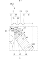
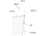
- Fig. 4 is an enlarged view of region IV shown in Fig. 3.
- the drill 1 in this embodiment has a first flank 15, a second flank 17, and a third flank 19 as flank surfaces 9. Note that in Figure 4, these flank surfaces are hatched to facilitate visual understanding of the areas of the first flank 15, the second flank 17, and the third flank 19.
- the first flank 15 is a flat surface that extends from the rotation axis O1 toward the outer periphery and approaches the rear end 3b as it approaches the outer periphery.
- the second flank 17 is a concavely curved surface that extends from the first flank 15 toward the outer periphery.
- the third flank 19 is a flat surface that extends from the second flank 17 toward the outer periphery and approaches the rear end 3b as it approaches the outer periphery.
- the first flank 15 and the third flank 19 are flat surfaces
- the second flank 17 is a concave surface that connects these surfaces.
- the second clearance surface 17 and the third clearance surface 19, which are located away from the rotation axis O1, may be inclined so as to approach the rear end 3b as they move toward the rear in the rotation direction Y1 (the opposite side to the rotation direction Y1).
- the angle of this inclination is the so-called clearance angle.
- insert 1a shown in FIG. 2 the first flank 15 and the second flank 17 are smoothly connected, and no ridge line is formed at the boundary between these surfaces.
- the second flank 17 and the third flank 19 are smoothly connected, and no ridge line is formed at the boundary between these surfaces. Note that "no ridge line is formed at the boundary" in the above means that the ridge line cannot be discerned with the naked eye, and does not include ridge lines caused by microscopic irregularities on the order of surface roughness.
- Figure 5 is a side view of the insert shown in Figure 3 as viewed from the A1 direction.
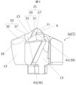
- Figure 6 is a side view of the insert shown in Figure 3 as viewed from the A2 direction.
- Figure 13 is an enlarged view of the same area as shown in Figure 4.
- the cutting edge 11 has an inner cutting edge 21 located along the first flank 15, a central cutting edge 23 located along the second flank 17, and an outer cutting edge 25 located along the third flank 19. Since the cutting edge 11 is located at the front edge of the flank 9 in the rotational direction Y1, the first flank 15 may be considered to extend from the inner cutting edge 21 toward the rear in the rotational direction Y1.
- the second flank 17 may be considered to extend rearward in the rotational direction Y1 from the central cutting edge 23
- the third flank 19 may be considered to extend rearward in the rotational direction Y1 from the outer cutting edge 25.
- the central cutting edge 23 is a term that indicates the relative positional relationship with the inner cutting edge 21 and the outer cutting edge 25, and is not limited to a configuration in which the central cutting edge 23 is located in the radial middle part of the drill 1, nor is it limited to a configuration in which the middle part of the cutting edge 11 in the longitudinal direction is included in the central cutting edge 23.
- the inner cutting edge 21 Since the first flank 15 has a surface configuration approaching the rear end 3b as it approaches the outer periphery, the inner cutting edge 21 also has a surface configuration approaching the rear end 3b as it approaches the outer periphery.
- the inner cutting edge 21 has a chisel edge 27 and a first cutting edge 29.
- the chisel edge 27 extends from the rotation axis O1 toward the outer periphery.
- the chisel edge 27 is the part of the cutting edge 11 that is closest to the rotation axis O1.
- the cutting edge is located at the intersection of the flank and rake face.
- the cutting edge is formed by the intersection of multiple flank faces corresponding to the multiple cutting edges. This type of area is called the chisel edge.
- the chisel edge 27 has a straight line shape.
- the chisel edge 27 extends from the rotation axis O1 toward the outer periphery, when the cutting edge 11 is viewed from the tip side, in other words when viewed from the tip, the chisel edge 27 extends straight in the radial direction from a point corresponding to the rotation axis O1, and the radial rake (radial rake angle) of the chisel edge 27 is 0.
- the first cutting edge 29 extends from the chisel edge 27 toward the outer periphery.
- the chisel edge 27 is formed by the intersection of multiple flanks 9, while the first cutting edge 29 is formed by the intersection of the first flank 15 and the rake face. Since the inner cutting edge 21 has the first cutting edge 29, it is easy to ensure a wide rake face area. In addition, it is easy to protrude the chisel edge 27 toward the tip side. This makes it easy for the chisel edge 27 to stably bite into the workpiece.
- the first cutting edge 29 may be, for example, formed of a single linear portion, or may be formed of multiple portions, as in the non-limiting example shown in FIG. 4.
- the first cutting edge 29 has a first portion 31 and a second portion 33.
- the first portion 31 is a portion located closer to the rotation axis O1 than the second portion 33
- the second portion 33 is a portion located on the outer periphery side than the first portion 31.
- the first portion 31 and the second portion 33 may each be linear.
- the radial rakes in the first portion 31 and the second portion 33 may each be negative.
- the radial rake ⁇ 2 in the second portion 33 may be a negative value that is greater (in absolute value) than the radial rake ⁇ 1 in the first portion 31.
- the cutting load applied to the first portion 31 and the cutting load applied to the second portion 33 are partially offset, as is clear from the vector composition of the direction of the cutting load applied to the first portion 31 and the direction of the cutting load applied to the second portion 33.
- the durability of the cutting edge 11 at the boundary between the first portion 31 and the second portion 33 is increased.
- the cutting load is less likely to concentrate on specific points of the first portion 31 and the second portion 33, further improving the durability of the cutting edge 11.
- the radial rake being a negative value means that the part of the target cutting edge 11 is inclined radially toward the rear in the rotational direction Y1 as it approaches the outer periphery.
- the radial rake being a positive value means that the part of the target cutting edge 11 is inclined radially toward the front in the rotational direction Y1 as it approaches the outer periphery.
- the first portion 31 When viewed from the tip, the first portion 31 may be longer than the second portion 33.
- the first cutting edge 29 When the first cutting edge 29 has the first portion 31 and the second portion 33, the first cutting edge 29 is configured such that the boundary between the first portion 31 and the second portion 33 protrudes forward in the rotational direction Y1.
- the central cutting edge 23 located along the second flank 17 in the front in the rotation direction Y1 has a concave curved shape. More specifically, the central cutting edge 23 has a concave curved shape that is slightly recessed toward the rear in the rotation direction Y1 when viewed from the tip.
- the central cutting edge 23 has a concave curved shape recessed toward the rear end 3b when viewed from the front in the rotation direction Y1 (see Figures 2, 5, and 6).
- the central cutting edge 23 may be configured such that the radius of curvature when viewed from the front in the rotation direction Y1 is smaller than the radius of curvature when viewed from the tip.
- the outer cutting edge 25 located along the third flank 19 in the front in the rotation direction Y1 has a second cutting edge 35 having a concave curved shape extending toward the outer periphery.
- the second cutting edge 35 has a concave curved shape recessed toward the rear in the rotation direction Y1 when viewed from the tip.
- the outer cutting edge 25 may be longer than the inner cutting edge 21 and the central cutting edge 23.
- the amount of workpiece cut by the outer cutting edge 25 is greater than that by the inner cutting edge 21 and the central cutting edge 23.
- the outer cutting edge 25 functions as the main cutting edge in the cutting process, the outer cutting edge 25 is also called the main cutting edge.
- the second cutting edge 35 When viewed from the tip, the second cutting edge 35 has a concave curved shape recessed toward the rear in the rotational direction Y1. When viewed from the front in the rotational direction Y1, the second cutting edge 35 also has a concave curved shape recessed slightly toward the rear end 3b (see Figures 2, 5, and 6).
- the second cutting edge 35 may be configured such that the radius of curvature when viewed from the tip is smaller than the radius of curvature when viewed from the front in the rotational direction Y1.
- the outer cutting edge 25 also has a configuration that approaches the rear end 3b as it approaches the outer periphery. Therefore, the third flank 19 is inclined so as to approach the rear end 3b as it approaches the outer periphery, and the outer cutting edge 25 is also inclined so as to approach the rear end 3b as it approaches the outer periphery. Because the outer cutting edge 25 has an inclined configuration in this way, the direction of travel of the drill 1 is less likely to deviate even at the stage when the outer cutting edge 25 bites into the workpiece, and good linear stability of the drill 1 is easily ensured.
- the inner cutting edge 21 located along the first flank 15 has the first cutting edge 29 in addition to the chisel edge 27. Therefore, the chisel edge 27 easily protrudes toward the tip side, and the chisel edge 27 bites into the workpiece well.
- the third flank 19 is configured to be inclined so as to approach the rear end 3b as it approaches the outer periphery
- the outer cutting edge 25 is also configured to be inclined so as to approach the rear end 3b as it approaches the outer periphery. Therefore, good linear stability of the drill 1 is ensured even at the stage where the outer cutting edge 25 bites into the workpiece.
- At least a portion of the inner cutting edge 21 may be located on the tip 3a side of the rotation trajectory of an imaginary line extending the outer cutting edge 25 toward the rotation axis O1.
- a tangent to the outer cutting edge 25 at this end is set, passing through the end of the outer cutting edge 25 on the side of the rotation axis O1.
- This tangent is the virtual line mentioned above, and a rotation trajectory around the rotation axis O1 of this virtual line is set. At this time, at least a part of the inner cutting edge 21 may be located on the tip 3a side of this rotation trajectory.
- the chisel edge 27 is likely to protrude toward the tip side, and even at the stage when the outer cutting edge 25 bites into the workpiece, the chisel edge 27 is likely to bite into the workpiece stably.
- the outer cutting edge 25 may further include a third cutting edge 37 in addition to the second cutting edge 35 described above.
- the outer cutting edge 25 may further include a third cutting edge 37 having a linear shape extending from the central cutting edge 23 toward the second cutting edge 35.
- the cutting load is difficult to distribute in the central cutting edge 23 and the second cutting edge 35, which are concave curved shapes. Therefore, when the central cutting edge 23 and the second cutting edge 35, which are concave curved shapes, are connected, there is a risk that an excessively large cutting load will be applied near the boundary between the central cutting edge 23 and the second cutting edge 35. However, when the outer cutting edge 25 has the above-mentioned third cutting edge 37, the central cutting edge 23 can be separated from the second cutting edge 35. This improves the durability of the cutting edge 11.
- the angle at which the central cutting edge 23 and the second cutting edge 35 intersect tends to be small.
- the boundary between the central cutting edge 23 and the second cutting edge 35 tends to be sharp, and there is a risk that restrictions on cutting conditions (e.g., rotational speed, feed rate, etc.) will be greater in consideration of durability near the boundary between the central cutting edge 23 and the second cutting edge 35.
- the outer cutting edge 25 has the above-mentioned third cutting edge 37, the cutting edge 11 is less likely to have a sharp portion as described above, and therefore the durability of the cutting edge 11 is improved from this viewpoint as well.
- FIG. 7 is a cross-sectional view taken along line VII-VII in Figure 4.
- Figure 8 is a cross-sectional view taken along line VIII-VIII in Figure 4.
- Figure 9 is a cross-sectional view taken along line IX-IX in Figure 4.
- Figure 10 is a cross-sectional view taken along line XX in Figure 4.
- Figure 11 is a cross-sectional view taken along line XI-XI in Figure 4.
- Figure 12 is a cross-sectional view taken along line XII-XII in Figure 4.
- the discharge groove 13 of the cutting portion 7 extends from the cutting edge 11 toward the rear end 3b.
- the discharge groove 13 extends from the second cutting edge 35 of the outer cutting edge 25 toward the rear end 3b.
- the discharge groove 13 is a portion used to discharge chips generated by the cutting edge 11 to the outside.
- the discharge groove 13 does not need to extend to the rear end 3b of the main body 3.
- the discharge groove 13 may be formed only in the cutting portion 7 and not in the gripping portion 5.
- the discharge groove 13 may extend in a spiral shape around the rotation axis O1, as in the non-limiting example shown in FIG. 1.
- the insert 1a may have a rake surface 39 located along the cutting edge 11 except for the chisel edge 27.
- the discharge groove 13 extends from the second cutting edge 35 of the outer cutting edge 25 toward the rear end 3b.
- the portion of the discharge groove 13 along the second cutting edge 35 can function as a rake surface 39 for the second cutting edge 35.
- the discharge groove 13 can function as a scooping surface 39 for the second cutting edge 35.
- the discharge groove 13 has a concave curved shape, so the second cutting edge 35 located at the intersection of the flat third relief surface 19 and the discharge groove 13 can be shown as having a concave curved shape.
- the groove that forms the bottom cutting edge is sometimes called a gash, and as shown in an example in FIG. 2, in the drill 1 of this embodiment, the cutting portion 7 (insert 1a) may have a flat first gash surface 41 that extends from the first portion 31 toward the rear end 3b.
- the first gash surface 41 can function as a rake surface 39 for the first portion 31.
- the axial rake ⁇ 1 of the first gash surface 41 may be positive.
- the chisel edge 27 adjacent to the first portion 31 is located on the ridge where the two flank surfaces 9 intersect, and therefore chips at the chisel edge 27 are difficult to discharge.
- chips generated at the chisel edge 27 are easily discharged through the first gash surface 41. Therefore, chip clogging is difficult to occur.
- the axial rake ⁇ 1 of the first gash surface 41 being positive means that in a cross section (cross section shown in FIG. 7) that is perpendicular to the first portion 31 when viewed from the tip and parallel to the rotation axis O1, the first gash surface 41 is inclined toward the rear in the rotation direction Y1 as it moves away from the first portion 31.
- the axial rake may be replaced with the rake angle (rake angle in the axial direction).
- the cutting portion 7 may have a flat second gash surface 43 extending from the second portion 33, the central cutting edge 23, and the third cutting edge 37.
- the second gash surface 43 may function as a rake surface 39 for the second portion 33, the central cutting edge 23, and the third cutting edge 37.
- the second cutting edge 35 has a concave curved shape, and the second portion 33, the central cutting edge 23, and the third cutting edge 37 are located closer to the rotation axis O1 than the second cutting edge 35. Therefore, the cutting speed at the second portion 33, the central cutting edge 23, and the third cutting edge 37 is slower than the cutting speed at the second cutting edge 35. Therefore, the flow of chips generated at the second portion 33, the central cutting edge 23, and the third cutting edge 37 is more likely to stagnate than the flow of chips generated at the second cutting edge 35.
- the axial rake ⁇ 2 of the second gash surface 43 may be positive, as in the example shown in Figures 8 to 10.
- chip clogging is even less likely to occur.
- the axial rake ⁇ 2 of the second gash surface 43 being positive means that, when viewed from the tip, the second gash surface 43 is perpendicular to either the second portion 33, the central cutting edge 23, or the third cutting edge 37, and in each cross section parallel to the rotation axis O1, the second gash surface 43 is inclined toward the rear in the rotation direction Y1 as it moves away from the second portion 33, the central cutting edge 23, or the third cutting edge 37.
- the portion of the discharge groove 13 along the second cutting edge 35 that can function as a scooping surface 39 for the second cutting edge 35 may be configured such that the axial rake ⁇ 3 is a positive value, similar to the first gash surface 41 and the second gash surface 43.
- the axial rake ⁇ 3 of the third surface at a portion of the second cutting edge 35 that is relatively close to the rotation axis O1 may have a larger positive value than the axial rake ⁇ 3 of the third surface at a portion of the second cutting edge 35 that is relatively far from the rotation axis O1 (on the outer periphery).
- the length of the central cutting edge 23 when viewed from the tip may be longer than the length of the second portion 33 and longer than the length of the third cutting edge 37.
- the central cutting edge 23, which has a concave curved shape is longer than the second portion 33 and the third cutting edge 37, which have straight lines, the flow of chips generated at the central cutting edge 23 is less likely to be affected by the flow of chips generated at the second portion 33 and the third cutting edge 37, and therefore chip clogging is less likely to occur.
- the second flank 17 may be smoothly connected to the first flank 15.
- smoothly connected means that no ridge is formed at the boundary between two adjacent faces.
- the second portion 33 of the inner cutting edge 21 and the central cutting edge 23 are smoothly connected. In this case, cutting load is less likely to concentrate on the boundary between the inner cutting edge 21 and the central cutting edge 23, improving the durability of the cutting edge 11.
- the second flank 17 may be smoothly connected to the third flank 19.
- the outer cutting edge 25 located along the third flank 19 and the central cutting edge 23 located along the second flank 17 are smoothly connected.
- the third cutting edge 37 of the outer cutting edge 25 and the central cutting edge 23 are smoothly connected. In this case, cutting load is less likely to concentrate at the boundary between the outer cutting edge 25 and the central cutting edge 23, improving the durability of the cutting edge 11.
- the second cutting edge 35 has a concave curved shape.
- the radial rake of the second cutting edge 35 does not have to be constant.
- the radial rake ⁇ 3 of the second cutting edge 35 at the first end 35a may be negative, and the radial rake ⁇ 4 of the second cutting edge 35 at the second end 35b may be positive.
- the chips generated at the first end 35a tend to flow toward the outer periphery. Therefore, the chips generated at the inner cutting edge 21 and the central cutting edge 23 tend to flow toward the discharge groove 13, and the chips generated at the inner cutting edge 21 and the central cutting edge 23 are less likely to become clogged.
- the radial rake ⁇ 4 of the second cutting edge 35 at the second end 35b is a positive value, the chips generated by the second cutting edge 35 tend to remain in the discharge groove 13 and are less likely to fly out to the outer periphery immediately after generation. Therefore, the machining hole in the workpiece is less likely to be damaged.
- the second clearance surface 17 may have a surface configuration that approaches the rear end 3b as it approaches the outer periphery, and in this case, the central cutting edge 23 may have a configuration that approaches the rear end 3b as it approaches the outer periphery.
- the central cutting edge 23 when viewed from the tip, may have a negative radial rake (not shown) of an imaginary line connecting one end point connected to the inner cutting edge 21 and the other end point connected to the outer cutting edge 25.
- the radial rake of the virtual straight line at the central cutting edge 23 may be a smaller negative value (in absolute value) than the radial rake ⁇ 2 at the second portion 33, and may be a smaller negative value than the radial rake ⁇ 1 at the first portion 31.
- the third cutting edge 37 of the outer cutting edge 25 may have a negative radial rake (not shown) when viewed from the tip.
- the radial rake of the third cutting edge 37 may be a negative value that is smaller (in absolute value) than the radial rake of the central cutting edge 23.
- the outer diameter of the cutting portion 7 is set to 6 mm to 42.5 mm.
- L is set to 1D to 12D.
- the material of the main body 3 may be, for example, a cemented carbide or a cermet.
- the composition of the cemented carbide may be, for example, WC-Co, WC-TiC-Co, or WC-TiC-TaC-Co.
- WC, TiC, and TaC may be hard particles
- Co may be a binder phase.
- the cermet may be a sintered composite material in which a ceramic component is combined with a metal.
- An example of a cermet is a titanium compound whose main component is titanium carbide (TiC) or titanium nitride (TiN). It goes without saying that the material of the main body 3 is not limited to the above composition.
- the surface of the body 3 may be coated with a coating using a chemical vapor deposition (CVD) method or a physical vapor deposition ( PVD ) method.
- the composition of the coating may include, for example, titanium carbide (TiC), titanium nitride (TiN), titanium carbonitride (TiCN), and alumina ( Al2O3 ).
- the drill 1 When the drill 1 has an insert 1a and a holder 1b, the drill 1 may be replaced with the insert 1a, except for the parts corresponding to the holder 1b in the description of the drill 1, the body 3, and the cutting part 7.
- the insert 1a in this disclosure can be said to have the following configuration.
- the insert 1a in this disclosure has a main body portion extending from the tip 3a to the rear end 3b along the rotation axis O1.
- the main body portion has a clearance surface 9 located at the tip 3a, a cutting edge 11 located at the front edge of the clearance surface 9 in the rotation direction Y1, and a discharge groove 13 extending from the cutting edge 11.
- the clearance surface 9 has a flat first clearance surface 15 that extends from the rotation axis O1 toward the outer periphery and approaches the rear end 3b as it approaches the outer periphery, a concavely curved second clearance surface 17 that extends from the first clearance surface 15 toward the outer periphery, and a flat third clearance surface 19 that extends from the second clearance surface 17 toward the outer periphery and approaches the rear end 3b as it approaches the outer periphery.
- the cutting edge 11 has an inner cutting edge 21 located along the first flank 15, a central cutting edge 23 located along the second flank 17, and an outer cutting edge 25 located along the third flank 19.
- the inner cutting edge 21 has a chisel edge 27 extending from the rotation axis O1 toward the outer periphery, and a first cutting edge 29 extending from the chisel edge 27 toward the outer periphery.
- the central cutting edge 23 has a concave curved shape
- the outer cutting edge 25 has a second cutting edge 35 that also has a concave curved shape extending toward the outer periphery.
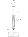
- the machined product 101 may be produced by cutting a workpiece 103.
- the manufacturing method of the machined product 101 may include the following steps (1) to (4).
- steps (1) and (2) may be performed, for example, by fixing the workpiece 103 on the table of a machine tool to which the drill 1 is attached, and bringing the drill 1 closer to the workpiece 103 while rotating. Note that in step (2), it is sufficient that the workpiece 103 and the drill 1 are relatively close to each other, and for example, the workpiece 103 may be brought closer to the drill 1.
- cutting may be performed so that at least a portion of the cutting portion 7 in the main body 3 is located inside the machining hole 105.
- the gripping portion 5 in the main body 3 may be set to be located outside the machining hole 105.
- a portion of the cutting portion 7 on the rear end 3b side may be set to be located outside the machining hole 105.
- the above-mentioned portion can function as a margin area for chip discharge, and excellent chip discharge properties can be achieved through this area.
- step (4) similarly to the above-mentioned step (2), the workpiece 103 and the drill 1 only need to be separated from each other; for example, the workpiece 103 may be separated from the drill 1.
- the process of contacting the cutting edge 11 of the drill 1 with different locations on the workpiece 103 while keeping the drill 1 rotating may be repeated.
- Examples of the material of the workpiece 103 include aluminum, carbon steel, alloy steel, stainless steel, cast iron, and non-ferrous metals.
- the drill in the first aspect of the present disclosure has a rod-shaped body that can rotate around a rotation axis and extends from the tip to the rear end along the rotation axis.
- the body has a flank located at the tip, a cutting edge located at a front edge of the flank in the rotation direction, and an exhaust groove extending from the cutting edge.
- the flank has a flat first flank that extends from the rotation axis toward the outer periphery and approaches the rear end as it approaches the outer periphery, a concavely curved second flank that extends from the first flank toward the outer periphery, and a flat third flank that extends from the second flank toward the outer periphery and approaches the rear end as it approaches the outer periphery.
- the cutting edge has an inner cutting edge located along the first flank, a central cutting edge located along the second flank, and an outer cutting edge located along the third flank.
- the inner cutting edge has a chisel edge that extends from the rotation axis toward the outer periphery, and a first cutting edge that extends from the chisel edge toward the outer periphery.
- the central cutting edge has a concave curved shape
- the outer cutting edge has a second cutting edge having a concave curved shape extending toward the outer periphery.
- the drill in aspect 2 of the present disclosure is based on aspect 1, and has the element that the outer cutting edge further has a third cutting edge that is linear and extends from the central cutting edge toward the second cutting edge.
- the drill in aspect 3 of the present disclosure is based on aspect 1 or 2, and has the following elements: the first cutting edge has a first portion that is a negative radial rake, and a second portion that is located on the outer periphery side of the first portion and has a larger negative radial rake than the first portion.
- the drill in aspect 4 of the present disclosure is based on any one of aspects 1 to 3, and has the element that the first portion and the second portion are each linear.
- the drill in aspect 5 of the present disclosure is based on any one of aspects 1 to 4, and has the following elements: the body further has a flat first gash surface extending from the first portion, and the axial rake at the first gash surface is a positive value.
- the drill in aspect 6 of the present disclosure is based on any one of aspects 1 to 5, and has the following element: the body further has a flat second gash surface extending from the second portion, the central cutting edge, and the third cutting edge.
- the drill in aspect 7 of the present disclosure is based on aspect 6, and has the element that the axial rake at the second gash surface is a positive value.
- the drill in aspect 8 of the present disclosure is based on any one of aspects 1 to 7, and has the element that the second flank is smoothly connected to the first flank.
- the drill in aspect 9 of the present disclosure is based on any one of aspects 1 to 8, and has the element that the second flank is smoothly connected to the third flank.
- the drill in aspect 10 of the present disclosure is based on any one of aspects 1 to 9, and has the following elements: the second cutting edge has a first end located on the inner circumference side and a second end located on the outer circumference side, and the radial rake of the second cutting edge at the first end is negative and the radial rake of the second cutting edge at the second end is positive.
- the drill in aspect 11 of the present disclosure is based on any one of aspects 1 to 10, and has an element in which at least a portion of the inner cutting edge is located closer to the tip than the rotation path of an imaginary line extending the outer cutting edge toward the rotation axis.
- the method for manufacturing a machined product in aspect 12 of the present disclosure includes the steps of rotating a drill in any one of aspects 1 to 11 around the rotation axis, bringing the cutting edge of the rotating drill into contact with a workpiece, and removing the drill from the workpiece.
Landscapes
- Engineering & Computer Science (AREA)
- Mechanical Engineering (AREA)
- Drilling Tools (AREA)
Priority Applications (4)
| Application Number | Priority Date | Filing Date | Title |
|---|---|---|---|
| JP2025516543A JPWO2024224768A1 (https=) | 2023-04-26 | 2024-02-19 | |
| CN202480026918.5A CN120981309A (zh) | 2023-04-26 | 2024-02-19 | 钻头及切削加工物的制造方法 |
| DE112024001899.8T DE112024001899T5 (de) | 2023-04-26 | 2024-02-19 | Bohrer und verfahren zur herstellung eines geschnittenen gegenstands |
| KR1020257035103A KR20250168415A (ko) | 2023-04-26 | 2024-02-19 | 드릴 및 절삭 가공물의 제조 방법 |
Applications Claiming Priority (2)
| Application Number | Priority Date | Filing Date | Title |
|---|---|---|---|
| JP2023072545 | 2023-04-26 | ||
| JP2023-072545 | 2023-04-26 |
Publications (1)
| Publication Number | Publication Date |
|---|---|
| WO2024224768A1 true WO2024224768A1 (ja) | 2024-10-31 |
Family
ID=93255973
Family Applications (1)
| Application Number | Title | Priority Date | Filing Date |
|---|---|---|---|
| PCT/JP2024/005716 Ceased WO2024224768A1 (ja) | 2023-04-26 | 2024-02-19 | ドリルおよび切削加工物の製造方法 |
Country Status (5)
| Country | Link |
|---|---|
| JP (1) | JPWO2024224768A1 (https=) |
| KR (1) | KR20250168415A (https=) |
| CN (1) | CN120981309A (https=) |
| DE (1) | DE112024001899T5 (https=) |
| WO (1) | WO2024224768A1 (https=) |
Citations (5)
| Publication number | Priority date | Publication date | Assignee | Title |
|---|---|---|---|---|
| US20020195279A1 (en) * | 2001-06-25 | 2002-12-26 | Bise Douglas E. | Monolithic roof bit cutting bit insert |
| JP2011104751A (ja) * | 2009-11-20 | 2011-06-02 | Mitsubishi Materials Corp | 座ぐり加工用ドリル |
| CN105033330A (zh) * | 2015-09-02 | 2015-11-11 | 苏州阿诺精密切削技术股份有限公司 | 低扭矩钻尖加强自修正钻 |
| JP2016078209A (ja) * | 2014-10-22 | 2016-05-16 | 株式会社ソディック | ドリル |
| US20210283696A1 (en) * | 2016-12-28 | 2021-09-16 | Seco Tools Ab | Twist drill and an exchangeable head for a twist drill |
Family Cites Families (2)
| Publication number | Priority date | Publication date | Assignee | Title |
|---|---|---|---|---|
| JP7375329B2 (ja) | 2019-04-17 | 2023-11-08 | 三菱マテリアル株式会社 | ドリル |
| JP6975353B1 (ja) | 2021-03-16 | 2021-12-01 | ダイジ▲ェ▼ット工業株式会社 | ドリル |
-
2024
- 2024-02-19 CN CN202480026918.5A patent/CN120981309A/zh active Pending
- 2024-02-19 JP JP2025516543A patent/JPWO2024224768A1/ja active Pending
- 2024-02-19 KR KR1020257035103A patent/KR20250168415A/ko active Pending
- 2024-02-19 WO PCT/JP2024/005716 patent/WO2024224768A1/ja not_active Ceased
- 2024-02-19 DE DE112024001899.8T patent/DE112024001899T5/de active Pending
Patent Citations (5)
| Publication number | Priority date | Publication date | Assignee | Title |
|---|---|---|---|---|
| US20020195279A1 (en) * | 2001-06-25 | 2002-12-26 | Bise Douglas E. | Monolithic roof bit cutting bit insert |
| JP2011104751A (ja) * | 2009-11-20 | 2011-06-02 | Mitsubishi Materials Corp | 座ぐり加工用ドリル |
| JP2016078209A (ja) * | 2014-10-22 | 2016-05-16 | 株式会社ソディック | ドリル |
| CN105033330A (zh) * | 2015-09-02 | 2015-11-11 | 苏州阿诺精密切削技术股份有限公司 | 低扭矩钻尖加强自修正钻 |
| US20210283696A1 (en) * | 2016-12-28 | 2021-09-16 | Seco Tools Ab | Twist drill and an exchangeable head for a twist drill |
Also Published As
| Publication number | Publication date |
|---|---|
| KR20250168415A (ko) | 2025-12-02 |
| CN120981309A (zh) | 2025-11-18 |
| JPWO2024224768A1 (https=) | 2024-10-31 |
| DE112024001899T5 (de) | 2026-02-26 |
Similar Documents
| Publication | Publication Date | Title |
|---|---|---|
| JP7168673B2 (ja) | 切削インサート、回転工具及び切削加工物の製造方法 | |
| US11311947B2 (en) | Rotary tool | |
| JP7386339B2 (ja) | ドリル及び切削加工物の製造方法 | |
| JP6711830B2 (ja) | ドリル及びそれを用いた切削加工物の製造方法 | |
| JP7344321B2 (ja) | 回転工具及び切削加工物の製造方法 | |
| JP7279167B2 (ja) | ドリル及び切削加工物の製造方法 | |
| WO2019088013A1 (ja) | ドリル及び切削加工物の製造方法 | |
| WO2019139075A1 (ja) | ドリル及び切削加工物の製造方法 | |
| JP6882517B2 (ja) | 回転工具 | |
| JP7142681B2 (ja) | ドリル及び切削加工物の製造方法 | |
| JP7526894B2 (ja) | 回転工具及び切削加工物の製造方法 | |
| WO2024224768A1 (ja) | ドリルおよび切削加工物の製造方法 | |
| JP7465980B2 (ja) | 回転工具及び切削加工物の製造方法 | |
| JP7499342B2 (ja) | 切削インサート、回転工具および切削加工物の製造方法 | |
| JP7279163B2 (ja) | 回転工具及び切削加工物の製造方法 | |
| JP7750804B2 (ja) | ドリル及び切削加工物の製造方法 | |
| WO2024224769A1 (ja) | ドリルおよび切削加工物の製造方法 | |
| JP7391108B2 (ja) | ドリル及び切削加工物の製造方法 | |
| WO2025023266A1 (ja) | ドリル及び切削加工物の製造方法 | |
| CN110691665B (zh) | 钻头以及切削加工物的制造方法 | |
| JP2018167341A (ja) | ドリル及び切削加工物の製造方法 | |
| WO2026088668A1 (ja) | ドリル、及び切削加工物の製造方法 | |
| WO2025197320A1 (ja) | ドリル及び切削加工物の製造方法 | |
| JP2025030995A (ja) | 回転工具及び切削加工物の製造方法 | |
| KR20260017408A (ko) | 드릴 및 절삭 가공물의 제조 방법 |
Legal Events
| Date | Code | Title | Description |
|---|---|---|---|
| 121 | Ep: the epo has been informed by wipo that ep was designated in this application |
Ref document number: 24796527 Country of ref document: EP Kind code of ref document: A1 |
|
| ENP | Entry into the national phase |
Ref document number: 2025516543 Country of ref document: JP Kind code of ref document: A |
|
| WWE | Wipo information: entry into national phase |
Ref document number: 2025516543 Country of ref document: JP |
|
| ENP | Entry into the national phase |
Ref document number: 1020257035103 Country of ref document: KR Free format text: ST27 STATUS EVENT CODE: A-0-1-A10-A15-NAP-PA0105 (AS PROVIDED BY THE NATIONAL OFFICE) |
|
| WWE | Wipo information: entry into national phase |
Ref document number: KR1020257035103 Country of ref document: KR Ref document number: 1020257035103 Country of ref document: KR |
|
| WWE | Wipo information: entry into national phase |
Ref document number: 202547102134 Country of ref document: IN |
|
| WWE | Wipo information: entry into national phase |
Ref document number: 112024001899 Country of ref document: DE |
|
| WWP | Wipo information: published in national office |
Ref document number: 202547102134 Country of ref document: IN |
|
| WWP | Wipo information: published in national office |
Ref document number: 1020257035103 Country of ref document: KR |
|
| WWP | Wipo information: published in national office |
Ref document number: 112024001899 Country of ref document: DE |
|
| 122 | Ep: pct application non-entry in european phase |
Ref document number: 24796527 Country of ref document: EP Kind code of ref document: A1 |