WO2024224451A1 - リニア搬送システム - Google Patents
リニア搬送システム Download PDFInfo
- Publication number
- WO2024224451A1 WO2024224451A1 PCT/JP2023/016134 JP2023016134W WO2024224451A1 WO 2024224451 A1 WO2024224451 A1 WO 2024224451A1 JP 2023016134 W JP2023016134 W JP 2023016134W WO 2024224451 A1 WO2024224451 A1 WO 2024224451A1
- Authority
- WO
- WIPO (PCT)
- Prior art keywords
- module
- mover
- electromagnetic force
- transport system
- linear transport
- Prior art date
- Legal status (The legal status is an assumption and is not a legal conclusion. Google has not performed a legal analysis and makes no representation as to the accuracy of the status listed.)
- Ceased
Links
Images








Classifications
-
- B—PERFORMING OPERATIONS; TRANSPORTING
- B65—CONVEYING; PACKING; STORING; HANDLING THIN OR FILAMENTARY MATERIAL
- B65G—TRANSPORT OR STORAGE DEVICES, e.g. CONVEYORS FOR LOADING OR TIPPING, SHOP CONVEYOR SYSTEMS OR PNEUMATIC TUBE CONVEYORS
- B65G54/00—Non-mechanical conveyors not otherwise provided for
- B65G54/02—Non-mechanical conveyors not otherwise provided for electrostatic, electric, or magnetic
-
- B—PERFORMING OPERATIONS; TRANSPORTING
- B65—CONVEYING; PACKING; STORING; HANDLING THIN OR FILAMENTARY MATERIAL
- B65G—TRANSPORT OR STORAGE DEVICES, e.g. CONVEYORS FOR LOADING OR TIPPING, SHOP CONVEYOR SYSTEMS OR PNEUMATIC TUBE CONVEYORS
- B65G23/00—Driving gear for endless conveyors; Belt- or chain-tensioning arrangements
- B65G23/22—Arrangements or mountings of driving motors
- B65G23/23—Arrangements or mountings of driving motors of electric linear motors
-
- H—ELECTRICITY
- H02—GENERATION; CONVERSION OR DISTRIBUTION OF ELECTRIC POWER
- H02K—DYNAMO-ELECTRIC MACHINES
- H02K41/00—Propulsion systems in which a rigid body is moved along a path due to dynamo-electric interaction between the body and a magnetic field travelling along the path
- H02K41/02—Linear motors; Sectional motors
- H02K41/03—Synchronous motors; Motors moving step by step; Reluctance motors
- H02K41/031—Synchronous motors; Motors moving step by step; Reluctance motors of the permanent magnet type
-
- H—ELECTRICITY
- H10—SEMICONDUCTOR DEVICES; ELECTRIC SOLID-STATE DEVICES NOT OTHERWISE PROVIDED FOR
- H10P—GENERIC PROCESSES OR APPARATUS FOR THE MANUFACTURE OR TREATMENT OF DEVICES COVERED BY CLASS H10
- H10P72/00—Handling or holding of wafers, substrates or devices during manufacture or treatment thereof
- H10P72/30—Handling or holding of wafers, substrates or devices during manufacture or treatment thereof for conveying, e.g. between different workstations
- H10P72/32—Handling or holding of wafers, substrates or devices during manufacture or treatment thereof for conveying, e.g. between different workstations between different workstations
- H10P72/3204—Handling or holding of wafers, substrates or devices during manufacture or treatment thereof for conveying, e.g. between different workstations between different workstations using magnetic elements
-
- B—PERFORMING OPERATIONS; TRANSPORTING
- B65—CONVEYING; PACKING; STORING; HANDLING THIN OR FILAMENTARY MATERIAL
- B65G—TRANSPORT OR STORAGE DEVICES, e.g. CONVEYORS FOR LOADING OR TIPPING, SHOP CONVEYOR SYSTEMS OR PNEUMATIC TUBE CONVEYORS
- B65G2812/00—Indexing codes relating to the kind or type of conveyors
- B65G2812/99—Conveyor systems not otherwise provided for
Definitions
- This disclosure relates to a linear transport system that uses the thrust of a linear motor.
- Patent Document 1 discloses a configuration in which stator modules having coils are arranged on both sides of the mover in a section where the transport paths branch, and electricity is passed through the coil of one of the stator modules to apply a lateral force that moves the mover in the branching direction.
- stator modules with coils are placed on both sides of the mover in the section where the conveying paths branch off, which creates the problem of increased weight for the linear conveying system.
- This disclosure has been made to solve the problems described above, and aims to provide a linear transport system that prevents weight increase even when the transport path branches.
- the linear transport system comprises a mover having a magnet arranged on its side, and a transport path in which a first module having a plurality of coils and moving the mover by the electromagnetic force of the plurality of coils, and a second module formed of a magnetic material and having no coils, are arranged along the moving direction of the mover, and the transport path is characterized in that it comprises a non-branched portion in which the first module is arranged on one side of the side of the mover, and a branched portion in which the first module is arranged on one side of the side of the mover and the second module is arranged on the other side.
- the linear conveying system disclosed herein has the advantage of preventing an increase in weight by using a second module that does not have a coil on one side of the mover at the branching point of the conveying path.
- FIG. 1 is a schematic configuration diagram showing a linear conveyance system according to a first embodiment of the present disclosure.
- 1 is a cross-sectional view showing a first module and a second module of a linear transport system according to a first embodiment of the present disclosure.
- 11 is a cross-sectional view showing a case where a mover advances in a positive X direction and is attracted in a negative Y direction at a branching portion of the linear transport system according to the first embodiment of the present disclosure.
- FIG. 11 is a cross-sectional view showing a case where a mover advances in the negative X direction and is attracted in the positive Y direction at a branching portion of the linear transport system according to the first embodiment of the present disclosure.
- FIG. 11 is a cross-sectional view showing a case where a mover advances in the positive X direction and is attracted in the positive Y direction at a branching portion of the linear transport system according to the first embodiment of the present disclosure.
- FIG. 11 is a cross-sectional view showing a case where a mover advances in the negative X direction and is attracted in the negative Y direction at a branching portion of the linear transport system according to the first embodiment of the present disclosure.
- FIG. 11 is a cross-sectional view showing a first module and a second module of a linear transport system according to a second embodiment of the present disclosure.
- FIG. 11 is a cross-sectional view showing a case where a mover advances in the positive X direction and is attracted in the negative Y direction at a branching portion of a linear transport system according to a second embodiment of the present disclosure.
- FIG. 11 is a cross-sectional view showing a case where a mover advances in the negative X direction and is attracted in the positive Y direction at a branching portion of a linear transport system according to a second embodiment of the present disclosure.
- FIG. 13 is a cross-sectional view showing a case where the mover advances in the positive X direction at a branching portion of a linear transport system according to a second embodiment of the present disclosure and is attracted in the positive Y direction before passing through a step.
- FIG. 11 is a cross-sectional view showing a case where a mover advances in the positive X direction and is attracted in the negative Y direction at a branching portion of a linear transport system according to a second embodiment of the present disclosure.
- FIG. 11 is a cross-sectional view showing a case where the mover advances in the positive X direction at a branching portion of a linear transport system according to a second embodiment of the present disclosure, passes through a step, and is then attracted in the positive Y direction.
- FIG. 13 is a cross-sectional view showing a case where the mover advances in the negative X direction at a branching portion of a linear transport system according to a second embodiment of the present disclosure and is attracted in the negative Y direction before passing through a step.
- FIG. 13 is a cross-sectional view showing a case where the mover advances in the negative X direction at a branching portion of a linear transport system according to a second embodiment of the present disclosure and is attracted in the negative Y direction before passing through a step.
- FIG. 11 is a cross-sectional view illustrating a case where a mover advances in the negative direction of the X direction at a branching portion of a linear transport system according to a second embodiment of the present disclosure, passes through a step, and is then attracted in the negative direction of the Y direction.
- 13 is a cross-sectional view showing a first module and a second module of a linear transport system according to a third embodiment of the present disclosure.
- FIG. A cross-sectional view showing a first module and a second module of a linear transport system according to a fourth embodiment of the present disclosure.
- FIG. 1 is a schematic diagram showing a linear conveying system according to a first embodiment of the present disclosure.
- the directions in this embodiment are defined as the X direction and the Y direction, respectively, as the moving direction of the mover 4 and the direction perpendicular to the moving direction of the mover 4, with the right side in the X direction being the positive direction and the upper side in the Y direction being the positive direction.
- the above-mentioned coordinate system is set and the explanation is given, but the X direction and the Y direction may be set appropriately depending on the configuration of the linear conveying system.
- the linear transport system 1 comprises a mover 4 with a magnet 41 arranged on its side, a first module 2 having a plurality of coils 22 and moving the mover 4 by the electromagnetic force of the plurality of coils 22, and a transport path 7 on which a second module 3 made of a magnetic material and having no coils is arranged along the moving direction of the mover 4.
- the transport path 7 comprises a non-branched portion 6 on one side of the side of the mover 4 where the first module 2 is arranged, and a branched portion 5 on one side of the side of the mover 4 where the first module 2 is arranged and the second module 3 is arranged on the other side.
- the first module 2 has an iron core 21 and a plurality of coils 22.
- the iron core 21 has a plurality of teeth 23, and the plurality of coils 22 are wound around any of the plurality of teeth 23.
- the second module 3 is made of a magnetic material, but does not have a coil.
- This second module 3 has a flat shape in which the distance from the magnet 41 of the mover 4 is constant, and is made of, for example, laminated steel plates in order to minimize loss during the movement of the mover 4.
- the first module 2 has a coil is shown, but the first module 2 and the second module 3 may be interchanged, and the first module 2 may be made of only a magnetic material, and the second module 3 may be made of an iron core and a coil.
- the mover 4 is located on one side of the first module 2 in the non-branching portion 6, and moves by receiving electromagnetic force from the first module 2.
- the mover 4 In the branching portion 5 of the conveying path 7, the mover 4 is located between the first module 2 and the second module 3, and is propelled by electromagnetic force from the multiple coils 22 of the first module 2.
- the moving direction of the mover 4 is the X direction
- the direction perpendicular to the moving direction is the Y direction.
- Each of the multiple movers 4 is independently controlled on the conveying path 7.
- a motor drive control device supplies current to each coil 22 of the first module 2 located near the mover 4.
- the current is not a three-phase UVW AC current, but a single-phase AC current that controls each phase independently, and a current is supplied to each coil 22 with an arbitrary waveform.
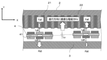
- the mover 4 has multiple magnets 41 arranged on both side surfaces. As shown in FIG. 2, the magnets 41 on both side surfaces of the mover 4 are arranged so that the magnetic pole directions of the magnets 41 are reversed in the Y direction of the mover 4. In the first embodiment, the arrangement of the magnets 41 in the Y direction may be the same, or the arrangement of the magnets 41 in the Y direction may be shifted in the X direction.
- FIG 3 is a cross-sectional view showing a case where the mover advances in the positive direction of the X direction and is attracted in the negative direction of the Y direction at the branching portion of the linear transport system according to the first embodiment of the present disclosure.
- the mover 4 is located between the first module 2 and the second module 3.
- Each of the multiple magnets 41 of the mover 4 faces the first module 2 and the second module 3.
- the coil 22 near the mover 4 is energized, and the first module 2 applies an electromagnetic force (branched lateral force) in a direction perpendicular to the traveling direction of the mover 4.
- the first module 2 moves the mover 4.
- the user of the linear transport system 1 selects a path in which the magnetic attraction force Fb1 becomes greater.
- the linear transport system 1 applies an electromagnetic force Fd from the positive direction to the negative direction in the Y direction to the movable element 4. Note that the gap between the movable element 4 and the first module 2 and the second module 3 at this time is an example and is not limited to this value.
- the linear transport system 1 can move the movable element 4 along a path in which the magnetic attraction force Fb1 between the second module 3 and the movable element 4 becomes greater. After the path is selected at the branching section 5, the mover 4 moves forward under the influence of electromagnetic force Fd from the first module 2 of the non-branching section 6.
- the magnetic attraction force Fb2 in the negative Y direction between the second module 3 and the mover 4 is greater than the magnetic attraction force Fa2 in the positive Y direction between the first module 2 and the mover 4 after the electromagnetic force is applied.
- the relationship between the distance La2 and Lb2 in the positive Y direction between the first module 2 and the mover 4 may be La2 ⁇ Lb2.
- the force acting on the mover 4 in the direction perpendicular to the moving direction is greater for the electromagnetic force from the second module 3 than for the electromagnetic force from the first module 2, so that the distance perpendicular to the moving direction between the mover 4 and the second module 3 is smaller.
- FIG. 4 is a cross-sectional view showing a case where the mover advances in the negative direction of the X direction and is attracted in the positive direction of the Y direction at the branching portion of the linear transport system according to the first embodiment of the present disclosure.
- FIG. 4 it is assumed that the mover 4 moves in the negative direction of the X direction at the branching portion 5, and when the magnetic attraction force Fb3 between the second module 3 and the mover 4 is greater than the magnetic attraction force Fa3 between the first module 2 and the mover 4, the user of the linear transport system 1 selects a path in the direction in which the magnetic attraction force Fa3 becomes greater.
- the linear transport system 1 applies an electromagnetic force to the mover 4 from the negative direction to the positive direction of the Y direction.
- the linear transport system 1 can move the mover 4 along a path in which the magnetic attraction force between the first module 2 and the mover 4 is greater. After a path is selected at the branching section 5, the mover 4 moves by receiving the electromagnetic force from the first module 2 at the non-branching section 6.
- the magnetic attraction force Fb3 between the second module 3 and the mover 4 in the negative direction in the Y direction is greater than the magnetic attraction force Fa3 between the first module 2 and the mover 4 in the positive direction in the Y direction before the electromagnetic force acts, but depending on the shape of the second module 3, the relationship between the distance La3 and Lb3 between the first module 2 and the mover 4 in the positive direction in the Y direction may be La3 ⁇ Lb3.
- FIG. 5 is a cross-sectional view showing a case where the mover advances in the positive direction of the X direction and is attracted in the positive direction of the Y direction at the branching portion of the linear transport system according to the first embodiment of the present disclosure.
- the mover 4 moves in the positive direction of the X direction at the branching portion 5 and the magnetic attraction force Fb5 between the second module 3 and the mover 4 is greater than the magnetic attraction force Fa5 between the first module 2 and the mover 4
- the linear transport system 1 applies an electromagnetic force to the mover 4 from the negative direction to the positive direction of the Y direction.
- the linear transport system 1 can advance the mover 4 in a path in which the magnetic attraction force between the first module 2 and the mover 4 becomes greater. After the path is selected through the branching section 5, the mover 4 moves forward under the electromagnetic force from the first module 2 of the non-branching section 6.
- the magnetic attraction force Fb5 of the magnet 41 in the negative Y direction of the second module 3 and the mover 4 is greater than the magnetic attraction force Fa5 of the magnet 41 in the positive Y direction of the first module 2 and the mover 4 before the electromagnetic force is applied.
- the relationship between the distance La5 between the first module 2 and the magnet 41 of the mover 4 in the positive Y direction and the distance Lb5 between the first module 2 and the magnet 41 of the mover 4 in the negative Y direction may be La5 ⁇ Lb5.
- the force acting on the mover 4 in the direction perpendicular to the moving direction is smaller for the electromagnetic force from the second module 3 than for the electromagnetic force from the first module 2, and this is characterized by the fact that the distance perpendicular to the moving direction between the mover 4 and the second module 3 becomes larger.
- FIG. 6 is a cross-sectional view showing a case where the mover advances in the negative direction of the X direction at the branching portion of the linear transport system according to the first embodiment of the present disclosure and is attracted in the negative direction of the Y direction.
- the mover 4 moves in the negative direction of the X direction at the branching portion 5
- the magnetic attraction force Fa7 of the first module 2 and the mover 4 in the positive direction of the Y direction is greater than the magnetic attraction force Fb7 of the second module 3 and the mover in the negative direction of the Y direction
- the user of the linear transport system 1 selects a path in which the magnetic attraction force Fb7 of the second module 3 and the mover 4 becomes larger.
- the linear transport system 1 applies an electromagnetic force from the positive direction of the Y direction to the negative direction of the Y direction to the mover 4.
- the distance Lb8 between the second module 3 and the mover 4 in the negative direction of the Y direction after the electromagnetic force is applied becomes smaller than the distance Lb7 between the second module 3 and the mover 4 in the negative direction of the Y direction before the electromagnetic force is applied. Due to this action, the linear transport system 1 can move the mover 4 along a path in which the magnetic attraction force between the second module 3 and the mover 4 in the negative Y direction becomes larger. After the path is selected at the branching section 5, the mover 4 moves by receiving the electromagnetic force from the first module 2 at the non-branching section 6.
- the magnetic attraction force Fb8 between the second module 3 and the mover 4 in the negative direction in the Y direction is greater than the magnetic attraction force Fa8 between the first module 2 and the mover 4 in the positive direction in the Y direction before the electromagnetic force is applied.
- the relationship between the distance La8 between the first module 2 and the mover 4 in the positive direction in the Y direction and the distance Lb8 between the first module 2 and the mover 4 in the negative direction in the Y direction may be La8 ⁇ Lb8.
- the linear transport system 1 includes a mover 4 having a magnet 41 arranged on its side, a transport path 7 in which a first module 2 having a plurality of coils 22 and moving the mover 4 by the electromagnetic force of the plurality of coils 22 and a second module 3 formed of a magnetic material without a coil are arranged in a plurality of positions in the traveling direction of the mover 4.
- the transport path 7 is characterized by having a non-branched section 6 in which the first module 2 is arranged on one side of the side of the mover 4, and a branched section 5 in which the first module 2 is arranged on one side of the side of the mover 4 and the second module 3 is arranged on the other side.
- the second module 3 is made of only a magnetic material and has no coil wound around it. Therefore, according to the linear conveying system according to the first embodiment of the present disclosure, even when the conveying path 7 branches, the second module 3 is used on one side of the movable element 4 at the branching portion 5, which prevents the weight of the linear conveying system 1 from increasing and prevents the linear conveying system 1 from becoming larger.
- the number of inverters for energizing the coils can be reduced compared to when the first module 2 is placed on both sides, which prevents the weight of the linear conveying system 1 from increasing and has the effect of preventing the linear conveying system 1 from becoming larger.
- the reduction in coils reduces wiring work, making motor assembly easier. Furthermore, since the shape of the second module 3, which does not have a coil, can be made smaller than the shape of the first module 2, the weight of the second module 3 can also be reduced. Note that the shape of the second module 3 may be the same as the iron core shape of the first module 2, the second module 3 may have multiple teeth to reduce cogging thrust, or the phase of the teeth of the first module and the teeth of the second module may be shifted.
- Embodiment 2 In the second embodiment, the same components as those in the first embodiment of the present disclosure are designated by the same reference numerals, and the description of the same or corresponding parts will be omitted.
- the linear transport system 1b according to the second embodiment will be described with reference to the drawings.
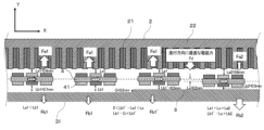
- the second module 31 is provided with a step 8 in a direction perpendicular to the traveling direction.
- This step 8 means that the average distance from the surface of the second module 31 to the surface of the magnet 41 changes with the position of the second module 31 in the X direction in the range where the second module 31 and the mover 4 face each other.
- the second module 31 is shaped so that the distance between the magnet 41 changes with the position, but the shape of the iron core 21 of the first module 2 may be changed, or both the shapes of the iron core 21 of the first module 2 and the second module 31 may be changed.
- FIG. 8 is a cross-sectional view showing a case where the mover advances in the positive X direction and is attracted in the negative Y direction at a branching portion of a linear conveying system according to embodiment 2 of the present disclosure.
- the second module 31 has a step 8 in a direction perpendicular to the direction of advancement, i.e., in the Y direction. Due to this step 8, the distance on the side of the mover 4 facing the second module 31 is smaller than the distance on the side facing the first module 2.
- the linear conveying system 1b applies an electromagnetic force from the positive to the negative direction in the Y direction in the area after the mover 4 has passed through the step 8.
- the distance Lb1' between the second module 31 and the mover 4 after passing through the step 8 is smaller than the distance Lb1 between the second module 31 and the mover 4 before passing through the step 8.
- the magnetic attraction force Fb1' after passing through the step 8 increases to
- the distance Lb2 between the second module 31 and the mover 4 after the electromagnetic force is applied becomes smaller than the distance Lb1' between the second module 31 and the mover 4 before the electromagnetic force is applied.
- This action allows the linear transport system 1 to move the mover 4 along a path in which the magnetic attraction force between the second module 31 and the mover 4 is greater.
- the mover 4 receives an electromagnetic force from the first module 2 at the non-branching section 6 and moves forward.
- G in equation (21) represents the size of the step 8 provided in the second module 31. From equation (24), by providing the step 8,
- Figure 9 is a cross-sectional view showing a case where the mover advances in the negative X direction and is attracted in the positive Y direction at a branching portion of a linear conveying system according to embodiment 2 of the present disclosure.
- Figure 9 assumes a case where, at branching portion 5, the mover 4 advances in the negative X direction, and when the magnetic attraction force Fb3 between the second module 31 and the mover 4 is greater than the magnetic attraction force Fa3 between the first module 2 and the mover 4, the user of linear conveying system 1b selects a path in which the magnetic attraction force Fa3 becomes greater.
- the linear conveying system 1b applies an electromagnetic force from the negative to the positive direction in the Y direction in the area after the mover 4 has passed through the step 8.
- the distance Lb3' between the second module 31 and the mover 4 after passing through the step 8 is larger than the distance Lb3 between the second module 31 and the mover 4 before passing through the step 8.
- the magnetic attraction force Fb3' becomes smaller,
- the linear transport system 1b can move the mover 4 along a path in which the magnetic attraction force between the first module 2 and the mover 4 is greater. After a path is selected at the branching section 5, the mover 4 moves forward by receiving an electromagnetic force from the first module 2 at the non-branching section 6.
- the state of the mover 4 on which the electromagnetic force acts after passing through the step 8 in FIG. 8 is the same as the state of the mover 4 before passing through the step 8 in FIG. 9 and before the electromagnetic force acts on it, and the relationship between the following equations (33) and (34) holds.
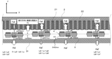
- FIG. 10 is a cross-sectional view showing a case where the mover advances in the positive X direction at a branching portion of a linear transport system according to embodiment 2 of the present disclosure, and is attracted in the positive Y direction before passing through a step.
- the mover 4 moves in the positive X direction, and when the magnetic attractive force Fb5 between the second module 31 and the mover 4 is greater than the magnetic attractive force Fa5 between the first module 2 and the mover 4, the user of linear transport system 1b selects a path in the direction in which the magnetic attractive force Fa5 becomes greater.
- FIG. 11 is a cross-sectional view showing a case where the mover advances in the positive direction of the X direction at the branching portion of the linear transport system according to the second embodiment of the present disclosure, passes through a step, and is attracted in the positive direction of the Y direction.
- the moving direction and the attracted direction of the mover 4 are the same as those in FIG. 10, but the location where the mover 4 is attracted to the second module 31 when determining the path at the branching portion 5 is different.
- the linear conveying system 1b applies an electromagnetic force in the positive direction in the Y direction in the area before the mover 4 passes through the step 8.
- the distance Lb5 between the second module 31 and the mover 4 before passing through the step 8 in FIG. 10 is larger than the distance Lb5' between the second module 31 and the mover 4 when the step 8 is passed without the application of electromagnetic force in FIG. 11. Since
- the relationship Fa5+Fb5 ⁇ 0 holds according to equation (40), and the magnetic attraction force in the negative direction in the Y direction is larger.
- the distance Lb6 between the second module 31 and the mover 4 becomes larger than the distance Lb5 between the second module 31 and the mover 4 before the electromagnetic force is applied, and the linear transport system 1b can move the mover 4 along a path in which the magnetic attraction force between the first module 2 and the mover 4 becomes larger.
- the state of the mover 4 before the electromagnetic force acts after passing through the step 8 in FIG. 8 is the same as the state of the mover 4 on which the electromagnetic force acts after passing through the step 8 in FIG. 10, and the relationship between the following equations (45) and (46) holds.
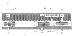
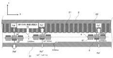
- FIG. 12 is a cross-sectional view showing a case where the mover advances in the negative X direction at a branching portion of a linear transport system according to embodiment 2 of the present disclosure, and is attracted in the negative Y direction before passing through a step.
- the mover 4 moves in the negative X direction at branching portion 5, and when the magnetic attraction force Fa7 between the first module 2 and the mover 4 is greater than the magnetic attraction force Fb7 between the second module 31 and the mover 4, the user of linear transport system 1b selects a path in the direction in which the magnetic attraction force Fb7 is greater.
- FIG. 13 is a cross-sectional view showing a case where the mover advances in the negative X direction at the branching portion of the linear transport system according to the second embodiment of the present disclosure, passes through a step, and is attracted in the negative Y direction.
- the moving direction and the attracted direction of the mover 4 are the same as those in FIG. 12, but the location where the mover 4 is attracted to the second module 31 when determining the path at the branching portion 5 is different.
- the linear conveying system 1b applies an electromagnetic force from the positive to the negative direction in the Y direction in the area before the mover 4 passes over the step 8.
- the distance Lb7 between the second module 31 and the mover 4 before passing over the step 8 is smaller than the distance Lb7' between the second module 31 and the mover 4 when the mover 4 passes over the step 8 without applying an electromagnetic force.
- holds, so the electromagnetic force that moves the mover 4 in the negative direction in the Y direction is smaller before passing over the step 8.
- the relationship Fa7+Fb7>0 holds, and the magnetic attraction force in the positive direction in the Y direction is larger.
- the distance Lb8 between the second module 31 and the mover 4 becomes smaller than the distance Lb7 between the second module 31 and the mover 4 before the electromagnetic force is applied, and the linear transport system 1b can move the mover 4 along a path in which the magnetic attraction force in the positive direction in the Y direction between the second module 31 and the mover 4 becomes larger.
- the second module 31 is made of only a magnetic material and has no coil wound around it. Therefore, according to the linear transport system 1b according to the second embodiment of the present disclosure, similar to the first embodiment, even when the transport path 7 branches, the second module 3 is used on one side of the side of the mover 4 at the branching portion 5, which prevents an increase in the weight of the linear transport system 1 and prevents the linear transport system 1 from becoming larger.
- the step 8 is provided in the second module 31 in a direction perpendicular to the traveling direction, when the movable element 4 is moved in the negative direction of the Y direction, the electromagnetic force moving the movable element 4 in the negative direction of the Y direction in the area with the step 8 is smaller than the electromagnetic force moving the movable element 4 in the negative direction of the Y direction in the absence of the step 8.
- the electromagnetic force moving the movable element 4 in the positive direction of the Y direction in the area with the step 8 is smaller than the electromagnetic force moving the movable element 4 in the positive direction of the Y direction in the absence of the step 8.
- the electromagnetic force moving the movable element 4 in the positive direction of the Y direction in the area before passing the step 8 is smaller than the electromagnetic force moving the movable element 4 in the positive direction of the Y direction after passing the step 8.
- the electromagnetic force that moves the mover 4 in the negative Y direction in the area before the step 8 is smaller than the electromagnetic force that moves the mover 4 in the negative Y direction after passing through the step 8.
- the second module 3 may be shaped so that the distance between the first module 2 and the second module 3 in a direction perpendicular to the traveling direction of the mover 4 changes along the traveling direction of the mover 4. In this case, the distance between the first module 2 and the second module 3 in a direction perpendicular to the traveling direction of the mover 4 may become narrower or wider along the traveling direction.
- Embodiment 3 the same components as those in the first embodiment of the present disclosure are designated by the same reference numerals, and descriptions of the same or corresponding parts are omitted.
- a linear transport system 1c according to the third embodiment will be described with reference to the drawings.
- FIG. 14 is a cross-sectional view showing the first module and the second module of the linear transport system according to the third embodiment of the present disclosure.
- the second module 32 in the linear transport system 1c according to the third embodiment of the present disclosure, in addition to the configuration of the first embodiment, the second module 32 is provided with an inclined portion 9 inclined in a direction perpendicular to the traveling direction.
- this inclined portion 9 By providing this inclined portion 9, the distance between the second module 32 and the mover 4 changes smoothly.
- the shape of this inclined portion 9 may be inclined so that the distance between the second module 32 and the mover 4 is narrowed or widened in the direction perpendicular to the traveling direction of the mover 4.
- the second module 32 is made of only a magnetic material, and no coil is wound around it, as in the first embodiment. Therefore, according to the linear transport system 1c according to the third embodiment of the present disclosure, even when the transport path 7 branches, as in the first embodiment, the second module 3 is used at the branching portion 5, which prevents an increase in the weight of the linear transport system 1 and prevents the linear transport system 1 from becoming larger.
- the distance between the second module 32 and the mover 4 changes smoothly. Therefore, the magnetic flux distribution between the magnet 41 of the mover 4 and the second module 32 also changes smoothly, and the cogging thrust generated in the mover 4 can be reduced.
- Embodiment 4 the same components as those in the first embodiment of the present disclosure are designated by the same reference numerals, and descriptions of the same or corresponding parts are omitted.
- a linear conveyance system 1d according to the fourth embodiment will be described with reference to the drawings.
- FIG. 15 is a cross-sectional view showing the first module and the second module of the linear transport system according to the fourth embodiment of the present disclosure.
- the linear transport system 1d according to the fourth embodiment of the present disclosure has, in addition to the configuration of the first embodiment, the second module 33 has a symmetric shape with respect to an axis perpendicular to the traveling direction of the mover 4.
- FIG. 15 shows, as an example, a case in which the inclined portion 9 is symmetrically provided on the second module 33.
- the symmetric shape of the second module 33 in this case may be a shape that is linearly symmetric with respect to the axis perpendicular to the traveling direction, or a shape that is rotationally symmetric. Note that the symmetric shape may be plane symmetric with respect to a plane perpendicular to the traveling direction, and is not limited to these.
- the second module 32 is made of only a magnetic material and has no coil wound around it. Therefore, according to the linear transport system 1d according to the fourth embodiment of the present disclosure, similar to the first embodiment, even when the transport path 7 branches, the second module 3 is used on one side of the side of the mover 4 at the branching portion 5, which prevents an increase in the weight of the linear transport system 1 and prevents the linear transport system 1 from becoming larger.
- the second module 33 has a shape symmetrical with respect to an axis perpendicular to the traveling direction of the mover 4, so that the distance between the first module 2 and the magnet 41 of the mover 4 and the distance between the second module 33 and the magnet 41 of the mover 4 are constant, and the cogging thrust generated when the mover 4 transfers from the non-branching section 6 to the branching section 5 can be reduced.
- Embodiment 5 the same components as those in the first embodiment of the present disclosure are designated by the same reference numerals, and the description of the same or corresponding parts will be omitted.
- a linear conveyance system 1e according to the fifth embodiment will be described with reference to the drawings.
- the linear transport system 1e includes a switching section 10 between the non-branching section 6 and the branching section 5 of the transport path 7, in which the distance between the first module 2 and the second module 3 in the direction perpendicular to the moving direction of the mover 4 decreases as the mover 4 moves from the non-branching section 6 to the branching section 5.
- the switching section 10 is made of a magnetic material and does not have a coil. This magnetic material is made of laminated steel plates or the like in order to minimize loss during the advancement of the mover 4.
- the switching section 10 may be integrated with the second module 34, and the distance between the magnet 41 of the mover 4 and the switching section 10 may gradually decrease, and may finally become the same as the distance between the second module 34 at the branching section 5 and the magnet 41 of the mover 4.
- the second module 34 is composed only of a magnetic material without a coil, and no coil is wound around it. Therefore, according to the linear transport system 1e according to the fifth embodiment of the present disclosure, similar to the first embodiment, even when the transport path 7 branches, the second module 3 is used on one side of the side of the mover 4 at the branching portion 5, which prevents an increase in the weight of the linear transport system 1 and prevents the linear transport system 1 from becoming larger.
- the linear conveying system 1e includes a switching section 10 in which the distance between the second module 34 and the mover 4 becomes smaller when the conveying path 7 switches from the non-branching section 6 to the branching section 5, and the distance between the second module 34 and the mover 4 becomes larger when the conveying path 7 switches from the branching section 5 to the non-branching section 6. Therefore, as the mover 4 moves in the traveling direction, the distance between the switching section 10 and the magnet 41 of the mover 4 gradually becomes equal to the distance between the second module 34 of the branching section 5 and the magnet 41 of the mover 4, so that the change in permeance becomes gradual and the cogging thrust can be reduced.
- Embodiment 6 the same components as those in the first embodiment of the present disclosure are designated by the same reference numerals, and descriptions of the same or corresponding parts will be omitted.
- a linear transport system if according to the sixth embodiment will be described with reference to the drawings.
- FIG. 17 is a cross-sectional view showing the first module and the second module of the linear transport system according to the sixth embodiment of the present disclosure.
- the linear transport system 1f according to the sixth embodiment of the present disclosure includes a movable mechanism 11 provided in the second module 35, which moves the second module 35 in a direction perpendicular to the traveling direction and changes the traveling direction of the mover 4.
- the movable mechanism 11 By including the movable mechanism 11, the position of the second module 35 can be changed, and the distance between the second module 35 and the magnet 41 of the mover 4 can be adjusted as desired.
- the second module 35 is moved in a direction perpendicular to the direction of travel, and the path of the mover 4 is selected by the attractive force of the second module 35 and the magnet 41.
- the attractive force in the positive Y direction is large, but by using the movable mechanism 11 so that the distance to the second module 35 decreases as the mover 4 progresses, the attractive force in the negative Y direction increases.
- the force acting on the entire mover 4 becomes negative in the Y direction, the mover 4 and the second module 35 move together.
- multiple second modules 35 may be provided, and the multiple second modules 35 may be provided with movable mechanisms 11.
- the second module 35 is made of only a magnetic material and has no coil wound around it. Therefore, according to the linear transport system 1f according to the sixth embodiment of the present disclosure, like the first embodiment, even when the transport path 7 branches, the second module 3 is used on one side of the side of the mover 4 at the branching portion 5, which prevents an increase in the weight of the linear transport system 1 and prevents the linear transport system 1 from becoming larger.
- a movable mechanism 11 is provided in the second module 35, which moves the second module 35 in a direction perpendicular to the traveling direction and changes the traveling direction of the mover 4. Therefore, since the electromagnetic force from the coil is not used when the mover 4 moves in a direction perpendicular to the traveling direction, the path can be changed without reducing the propulsive force on the mover 4.
Landscapes
- Engineering & Computer Science (AREA)
- Physics & Mathematics (AREA)
- Chemical & Material Sciences (AREA)
- Combustion & Propulsion (AREA)
- Electromagnetism (AREA)
- Power Engineering (AREA)
- Mechanical Engineering (AREA)
- Non-Mechanical Conveyors (AREA)
- Linear Motors (AREA)
Priority Applications (5)
| Application Number | Priority Date | Filing Date | Title |
|---|---|---|---|
| CN202380097315.XA CN120981412A (zh) | 2023-04-24 | 2023-04-24 | 线性输送系统 |
| JP2024545050A JP7605383B1 (ja) | 2023-04-24 | 2023-04-24 | リニア搬送システム |
| PCT/JP2023/016134 WO2024224451A1 (ja) | 2023-04-24 | 2023-04-24 | リニア搬送システム |
| DE112023006286.2T DE112023006286T5 (de) | 2023-04-24 | 2023-04-24 | Linearfördersystem |
| KR1020257033401A KR20250167638A (ko) | 2023-04-24 | 2023-04-24 | 리니어 반송 시스템 |
Applications Claiming Priority (1)
| Application Number | Priority Date | Filing Date | Title |
|---|---|---|---|
| PCT/JP2023/016134 WO2024224451A1 (ja) | 2023-04-24 | 2023-04-24 | リニア搬送システム |
Publications (1)
| Publication Number | Publication Date |
|---|---|
| WO2024224451A1 true WO2024224451A1 (ja) | 2024-10-31 |
Family
ID=93256023
Family Applications (1)
| Application Number | Title | Priority Date | Filing Date |
|---|---|---|---|
| PCT/JP2023/016134 Ceased WO2024224451A1 (ja) | 2023-04-24 | 2023-04-24 | リニア搬送システム |
Country Status (5)
| Country | Link |
|---|---|
| JP (1) | JP7605383B1 (https=) |
| KR (1) | KR20250167638A (https=) |
| CN (1) | CN120981412A (https=) |
| DE (1) | DE112023006286T5 (https=) |
| WO (1) | WO2024224451A1 (https=) |
Citations (6)
| Publication number | Priority date | Publication date | Assignee | Title |
|---|---|---|---|---|
| WO2019171456A1 (ja) * | 2018-03-06 | 2019-09-12 | 株式会社Fuji | 搬送装置、及び搬送路 |
| US20190389675A1 (en) * | 2017-03-06 | 2019-12-26 | Ats Automation Tooling Systems Inc. | Linear motor conveyor system with diverter and method for design and configuration thereof |
| US20200180872A1 (en) * | 2017-05-18 | 2020-06-11 | Krones Ag | Magnet switch for a transport system |
| JP2020129854A (ja) * | 2019-02-07 | 2020-08-27 | 株式会社Fuji | キャリア及び搬送システム |
| JP7238149B2 (ja) * | 2019-10-04 | 2023-03-13 | 株式会社Fuji | 搬送装置、搬送システム及び搬送装置の制御方法 |
| JP7262680B1 (ja) * | 2022-02-21 | 2023-04-21 | 三菱電機株式会社 | リニア搬送システム |
Family Cites Families (1)
| Publication number | Priority date | Publication date | Assignee | Title |
|---|---|---|---|---|
| CN105813886B (zh) | 2013-09-21 | 2018-04-03 | 麦克纳莫绅有限公司 | 用于包装和其它用途的线性电机运输 |
-
2023
- 2023-04-24 DE DE112023006286.2T patent/DE112023006286T5/de active Pending
- 2023-04-24 WO PCT/JP2023/016134 patent/WO2024224451A1/ja not_active Ceased
- 2023-04-24 KR KR1020257033401A patent/KR20250167638A/ko active Pending
- 2023-04-24 CN CN202380097315.XA patent/CN120981412A/zh active Pending
- 2023-04-24 JP JP2024545050A patent/JP7605383B1/ja active Active
Patent Citations (6)
| Publication number | Priority date | Publication date | Assignee | Title |
|---|---|---|---|---|
| US20190389675A1 (en) * | 2017-03-06 | 2019-12-26 | Ats Automation Tooling Systems Inc. | Linear motor conveyor system with diverter and method for design and configuration thereof |
| US20200180872A1 (en) * | 2017-05-18 | 2020-06-11 | Krones Ag | Magnet switch for a transport system |
| WO2019171456A1 (ja) * | 2018-03-06 | 2019-09-12 | 株式会社Fuji | 搬送装置、及び搬送路 |
| JP2020129854A (ja) * | 2019-02-07 | 2020-08-27 | 株式会社Fuji | キャリア及び搬送システム |
| JP7238149B2 (ja) * | 2019-10-04 | 2023-03-13 | 株式会社Fuji | 搬送装置、搬送システム及び搬送装置の制御方法 |
| JP7262680B1 (ja) * | 2022-02-21 | 2023-04-21 | 三菱電機株式会社 | リニア搬送システム |
Also Published As
| Publication number | Publication date |
|---|---|
| CN120981412A (zh) | 2025-11-18 |
| DE112023006286T5 (de) | 2026-02-19 |
| JPWO2024224451A1 (https=) | 2024-10-31 |
| KR20250167638A (ko) | 2025-12-01 |
| JP7605383B1 (ja) | 2024-12-24 |
Similar Documents
| Publication | Publication Date | Title |
|---|---|---|
| US10917027B2 (en) | Method and long stator linear motor for transferring a transport unit at a transfer position | |
| WO2003003389A1 (en) | Introduction track magnet configuration | |
| US20210135558A1 (en) | Linear motor and transport system using the same | |
| JPH03112393A (ja) | 搬送装置 | |
| EP4292918A1 (en) | Electric stabilisers | |
| JP7605383B1 (ja) | リニア搬送システム | |
| GB2281664A (en) | Linear motor and elevator and conveyer using same | |
| KR101798548B1 (ko) | 선형 전동기 | |
| JP4320664B2 (ja) | 磁気浮上搬送装置 | |
| DE112023001257T5 (de) | Motorbaugruppe für einen lineardirektantriebsmotor | |
| US20240055967A1 (en) | Self guided linear induction motor system and method | |
| US7498700B2 (en) | Linear drive system | |
| JPH1052025A (ja) | リニアモータおよびその制御方法 | |
| US7834489B2 (en) | Synchronous linear motor | |
| JPH0880027A (ja) | リニアモータ | |
| US12617634B2 (en) | Linear conveyance system | |
| KR102775218B1 (ko) | 무선전원공급 선형이송시스템 | |
| US20250162823A1 (en) | Linear conveyance system | |
| TW202339995A (zh) | 非接觸供電設備 | |
| Markon et al. | Linear motor coils as brake actuators for multi-car elevators | |
| JPH06263365A (ja) | エレベータ装置 | |
| US4208596A (en) | Linear induction motor | |
| EP4656564A1 (en) | Hybrid shuttle for planar and long stator linear motors | |
| CA2408790A1 (en) | Transportation system with linear switched reluctance actuator for propulsion and levitation | |
| JPS63198570A (ja) | 金属缶類の搬送装置 |
Legal Events
| Date | Code | Title | Description |
|---|---|---|---|
| WWE | Wipo information: entry into national phase |
Ref document number: 2024545050 Country of ref document: JP |
|
| 121 | Ep: the epo has been informed by wipo that ep was designated in this application |
Ref document number: 23935234 Country of ref document: EP Kind code of ref document: A1 |
|
| ENP | Entry into the national phase |
Ref document number: 1020257033401 Country of ref document: KR Free format text: ST27 STATUS EVENT CODE: A-0-1-A10-A15-NAP-PA0105 (AS PROVIDED BY THE NATIONAL OFFICE) |
|
| WWE | Wipo information: entry into national phase |
Ref document number: KR1020257033401 Country of ref document: KR Ref document number: 1020257033401 Country of ref document: KR |
|
| WWE | Wipo information: entry into national phase |
Ref document number: 112023006286 Country of ref document: DE |
|
| WWP | Wipo information: published in national office |
Ref document number: 1020257033401 Country of ref document: KR |
|
| WWP | Wipo information: published in national office |
Ref document number: 112023006286 Country of ref document: DE |
|
| 122 | Ep: pct application non-entry in european phase |
Ref document number: 23935234 Country of ref document: EP Kind code of ref document: A1 |