WO2024218904A1 - 光増幅中継装置及び光増幅中継方法 - Google Patents
光増幅中継装置及び光増幅中継方法 Download PDFInfo
- Publication number
- WO2024218904A1 WO2024218904A1 PCT/JP2023/015621 JP2023015621W WO2024218904A1 WO 2024218904 A1 WO2024218904 A1 WO 2024218904A1 JP 2023015621 W JP2023015621 W JP 2023015621W WO 2024218904 A1 WO2024218904 A1 WO 2024218904A1
- Authority
- WO
- WIPO (PCT)
- Prior art keywords
- optical
- optical signal
- signal
- input
- amplifier
- Prior art date
- Legal status (The legal status is an assumption and is not a legal conclusion. Google has not performed a legal analysis and makes no representation as to the accuracy of the status listed.)
- Ceased
Links
Images



Classifications
-
- G—PHYSICS
- G02—OPTICS
- G02F—OPTICAL DEVICES OR ARRANGEMENTS FOR THE CONTROL OF LIGHT BY MODIFICATION OF THE OPTICAL PROPERTIES OF THE MEDIA OF THE ELEMENTS INVOLVED THEREIN; NON-LINEAR OPTICS; FREQUENCY-CHANGING OF LIGHT; OPTICAL LOGIC ELEMENTS; OPTICAL ANALOGUE/DIGITAL CONVERTERS
- G02F1/00—Devices or arrangements for the control of the intensity, colour, phase, polarisation or direction of light arriving from an independent light source, e.g. switching, gating or modulating; Non-linear optics
- G02F1/35—Non-linear optics
- G02F1/39—Non-linear optics for parametric generation or amplification of light, infrared or ultraviolet waves
-
- H—ELECTRICITY
- H04—ELECTRIC COMMUNICATION TECHNIQUE
- H04B—TRANSMISSION
- H04B10/00—Transmission systems employing electromagnetic waves other than radio-waves, e.g. infrared, visible or ultraviolet light, or employing corpuscular radiation, e.g. quantum communication
- H04B10/29—Repeaters
- H04B10/291—Repeaters in which processing or amplification is carried out without conversion of the main signal from optical form
- H04B10/293—Signal power control
Definitions
- the present invention relates to an optical amplifier relay device and an optical amplifier relay method.
- optical amplifiers are used to compensate for optical losses that occur in optical signals transmitted through the optical fiber.
- the transmission bandwidth of the optical transmission system is limited by the amplification bandwidth of the optical amplifier.
- the erbium-doped fiber amplifier is a typical rare earth doped optical amplifier.
- the amplification band of an erbium-doped optical fiber amplifier is a band of approximately 4 THz in the C-band or L-band, where the transmission loss in optical fiber is small. This band is a wavelength (frequency) band that is generally used in optical transmission using long-distance optical fiber.
- the amplification band may be shifted by changing the rare earth element added to the optical fiber.
- the transmission band may be expanded by arranging heterogeneous amplifiers with shifted amplification bands in parallel with each other. However, in these cases, the gain is reduced and the noise is increased in bands other than the C and L bands. Also, considering the cost of the optical transmission system, the operation of the optical transmission system, and the excessive optical loss caused by dividing the band of the optical signal into multiple band components, it is desirable to amplify the optical signal over a wide band by a single optical amplifier.
- optical parametric amplifiers have attracted attention.
- Optical parametric amplifiers amplify input optical signals by utilizing the nonlinear optical effect of a second-order or third-order nonlinear optical medium.
- An example of a second-order nonlinear optical medium is lithium niobate.
- An example of a third-order nonlinear optical medium is optical fiber.
- the amplification band of an optical parametric amplifier depends on the phase matching characteristics of the nonlinear optical medium used as the amplification medium. If the amplification medium is designed to achieve wideband phase matching characteristics, it becomes possible to amplify a wideband optical signal that exceeds the amplification band of an erbium-doped optical fiber amplifier.
- the amplification medium it is possible to amplify optical signals in various wavelength bands other than the C and L bands.
- a second-order nonlinear optical medium where a second harmonic is required for the pump light for the optical parametric amplification process, the difference between the frequency of the optical signal to be amplified and the frequency of the pump light is large.
- the difference in the effective refractive index for each band component becomes large, and it is not easy to design one that satisfies the phase matching conditions over a wide range of frequencies.
- Quasi-phase matching uses a periodically poled structure.
- a periodically poled structure is a structure in which regions with the sign of the nonlinear susceptibility reversed are periodically and alternately formed in the propagation axis direction of the nonlinear optical medium.
- Non-Patent Document 1 shows the possibility of realizing amplified relay transmission with a wide bandwidth exceeding 10 THz and an amplification gain of 15 dB.
- Non-Patent Document 1 uses an optical parametric amplifier that uses a periodically poled lithium niobate waveguide.
- phase conjugate light (idler light) of the amplified optical signal is generated at a frequency symmetrical with respect to the center frequency of the amplification band.
- the original optical signal optical signal before amplification
- the idler light needs to be transmitted. For this reason, optical components not used for transmission are removed without being extracted by a band-pass filter (BPF) after the optical signal is amplified.
- BPF band-pass filter
- the optical parametric amplifier When idler light is extracted as the optical signal used for transmission, the optical parametric amplifier also functions as an optical phase conjugate converter (see Non-Patent Document 2) or a wavelength converter (see Patent Document 1). In this way, one of the features of the optical parametric amplifier is that it functions not only as a simple optical amplifier but also as a variety of optical signal processing devices.
- the region of optical intensity of the input optical signal that causes saturation is called the "saturation region.”
- the high-speed response of the optical parametric amplification process means that the gain does not fluctuate with dynamic multiplexing and demultiplexing of wavelength channels, allowing the optical parametric amplifier to maintain a constant output optical intensity per channel.
- the high-speed response of the optical parametric amplification process causes nonlinear signal distortion in the optical signal when the optical parametric amplifier operates in the gain saturation region.
- the gain is constant relative to the optical intensity of the input optical signal, and the optical intensity of the output optical signal responds linearly to the optical intensity of the input optical signal.
- the pump light is used to amplify the input optical signal, and the amplification gain decreases due to the attenuation of the pump light.
- the optical parametric amplifier due to the high-speed response of the optical parametric amplifier, it follows the temporal changes in the optical intensity of the modulated input optical signal, causing the amplification gain to increase or decrease. As a result, the optical intensity of the output optical signal shows a nonlinear response to the optical intensity of the input optical signal. This phenomenon is called gain saturation.
- gain saturation in an amplifier with slow response generally refers only to the limitation of the optical intensity of the output optical signal.
- the amplification gain changes nonlinearly in response to the change in the optical intensity of the input optical signal over time.
- a gain occurs according to the amplitude level of the modulation symbol, resulting in nonlinear amplitude distortion in the optical signal. Therefore, the operating range (input/output range) of the optical parametric amplifier must be determined taking into account not only the upper limit of the optical intensity of the output optical signal, but also signal degradation caused by nonlinear distortion due to gain saturation.
- the optical intensity of the input optical signal fluctuates greatly over time, i.e., when the peak-to-average power ratio (PAPR) of the input optical signal is large, the nonlinearity of the amplification gain becomes prominent.
- Parameters that change the peak-to-average power ratio of the input optical signal include, for example, the modulation format of the input optical signal and the addition of chromatic dispersion due to transmission through an optical fiber. Therefore, the operating range (input/output range) of the optical parametric amplifier must be determined based on these parameters.
- Inter-channel crosstalk Another cause of signal degradation when an input optical signal passes through an optical parametric amplifier is inter-channel crosstalk due to unwanted wavelength conversion effects.
- Inter-channel crosstalk depends on the input optical intensity per channel and the frequency spacing between channels. For this reason, even if the total optical intensity of the input optical signals based on wavelength division multiplexed signals is the same, the effect of inter-channel crosstalk differs depending on the number of channels of the wavelength division multiplexed signal (number of WDM channels).
- number of WDM channels number of WDM channels
- the present invention aims to provide an optical amplifier repeater and an optical amplifier repeater method that are capable of amplifying optical signals while reducing the possibility that the amplification gain due to gain saturation becomes nonlinear due to changes in optical intensity over time.
- One aspect of the present invention is an optical amplifier repeater that includes a variable attenuator that attenuates the optical intensity of an input optical signal, a multiplexing section that multiplexes the input optical signal with the attenuated optical intensity and a background optical signal of the input optical signal, and a first optical amplifier that performs optical parametric amplification on the multiplexed input optical signal and background optical signal.
- One aspect of the present invention is an optical amplification relay method performed by an optical amplification relay device, the optical amplification relay method including the steps of attenuating the optical intensity of an input optical signal, combining the input optical signal with the attenuated optical intensity and a background optical signal of the input optical signal, and performing optical parametric amplification on the combined input optical signal and background optical signal.
- the present invention makes it possible to amplify optical signals while reducing the possibility that the amplification gain due to gain saturation will become nonlinear due to changes in optical intensity over time.
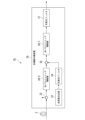
- FIG. 1 is a diagram illustrating an example of a configuration of an optical transmission system in a first embodiment.
- FIG. 2 is a diagram illustrating a configuration example of an optical parametric amplifier in the first embodiment.
- 4 is a flowchart showing an example of the operation of the optical amplifier repeater in the first embodiment.
- 5A to 5C are diagrams illustrating an example of the relationship between the amount of chromatic dispersion and the signal-to-noise ratio, and an example of the relationship between the amount of chromatic dispersion and the peak power to average power ratio in the first embodiment.
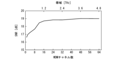
- 4 is a diagram illustrating an example of the relationship between the number of WDM channels and the signal-to-noise ratio in the first embodiment.
- FIG. 11 is a diagram illustrating an example of a configuration of an optical transmission system in a second embodiment.
- FIG. 2 is a diagram illustrating an example of a hardware configuration of a control device of an optical amplifier repeater in each embodiment.
- First Embodiment 1 is a diagram showing an example of the configuration of an optical transmission system 1a in the first embodiment.
- the optical transmission system 1a is a system that transmits an optical signal.
- the optical signal is generated based on, for example, a wavelength division multiplexed signal.
- the optical transmission system 1a includes a transmission line 2 and an optical amplifier repeater 3a.
- the transmission line 2 includes, for example, an optical fiber.
- the optical amplifier repeater 3a includes a variable attenuator 31, a branching unit 32, a spontaneous emission light source 33, a tunable optical filter 34, a signal multiplexing unit 35, and an optical parametric amplifier 36.
- the transmission path 2 transmits the optical signal to the optical amplifier repeater 3a.
- the variable attenuator 31 attenuates (variably attenuates) the optical intensity of the input optical signal before the branching unit 32 based on the measurement result of the optical intensity of the monitor light branched from the input optical signal by the branching unit 32.
- the variable attenuator 31 attenuates the optical intensity of the input optical signal to an optical intensity adjusted so that signal distortion due to gain saturation and inter-channel crosstalk does not occur in the input optical signal in the optical parametric amplifier 36.
- the variable attenuator 31 outputs the input optical signal with attenuated optical intensity to the branching unit 32.
- the branching unit 32 branches (extracts) monitor light from the input optical signal whose optical intensity has been attenuated by the variable attenuator 31.
- the branching unit 32 outputs the input optical signal whose optical intensity has been attenuated to the signal multiplexing unit 35.
- the branching unit 32 measures the optical intensity of the monitor light.
- the branching unit 32 measures the optical intensity of the input optical signal input to the signal multiplexing unit 35 based on the optical intensity of the monitor light.
- the branching unit 32 may measure the spectrum of the monitor light.
- the branching unit 32 outputs each measurement result to a control device (not shown).
- the control device controls the amount of attenuation of the optical intensity of the input optical signal by the variable attenuator 31 based on each measurement result.
- the spontaneous emission light source 33 is an amplified spontaneous emission (ASE) optical amplifier.
- the spontaneous emission amplifier is an optical amplifier that corresponds to the band used in the optical parametric amplifier 36.
- the spontaneous emission amplifier is a rare-earth doped fiber amplifier (e.g., an erbium doped optical fiber amplifier).
- the spontaneous emission light source 33 outputs the amplified spontaneous emission light to the tunable optical filter 34.
- the tunable optical filter 34 uses the amplified spontaneous emission light to generate a background optical signal of the input optical signal.
- the background optical signal is a signal that has a predetermined frequency component (pseudo wavelength division multiplexing signal) in a band (background) where no frequency components of the input optical signal exist.
- the tunable optical filter 34 outputs the background optical signal as a pseudo wavelength division multiplexing signal to the signal multiplexing unit 35.
- the signal multiplexing unit 35 multiplexes the input optical signal with attenuated optical intensity with the background optical signal.
- the signal multiplexing unit 35 outputs the multiplexed result of the input optical signal with attenuated optical intensity with the background optical signal to the optical parametric amplifier 36. This makes the frequency interval between channels in the band of the input optical signal to the optical parametric amplifier 36 constant. Since the optical intensity is kept constant by attenuating the optical intensity with the variable attenuator 31, it is possible to suppress signal distortion regardless of the modulation format (type) and state of the input optical signal.
- the amount of signal distortion is less dependent on parameters such as the modulation format and chromatic dispersion of the input optical signal because the correlation between the nonlinearity of the gain in optical parametric amplification and the time waveform of each channel is low. Therefore, it is possible to specify the allowable value of the optical intensity (input optical intensity) of the input optical signal in the optical parametric amplifier 36 without depending on parameters such as the modulation format and chromatic dispersion of the input optical signal.
- the optical parametric amplifier 36 (optical amplifier) performs optical parametric amplification on the result of combining the optical signal with adjusted optical intensity and the background optical signal.
- the tunable optical filter 37 performs gain equalization processing on the optical signal that has been optically parametrically amplified or wavelength converted.
- the tunable optical filter 37 also separates the background optical signal from the optical signal that has been gain equalized.
- the tunable optical filter 37 outputs the optical signal that has been gain equalized to a receiving device (not shown). As a result, the optical signal is relayed to the receiving device (not shown).
- FIG. 2 is a diagram showing an example of the configuration of the optical parametric amplifier 36 in the first embodiment.
- the optical parametric amplifier 36 includes a band splitter 361, a plurality of polarization splitters 362, a plurality of pump light combiners 363, a plurality of nonlinear optical media 364, a plurality of pump light splitters 365, a plurality of polarization combiners 366, and a band combiner 367.
- the pumping light multiplexing unit 363 includes an optical device such as a wavelength multiplexing filter.
- the pumping light multiplexing unit 363 may include an optical device such as a dichroic mirror.
- the nonlinear optical medium 364 optical amplifier
- PPLN periodically poled lithium niobate
- the pumping light demultiplexing unit 365 includes an optical device such as a wavelength multiplexing filter.
- the pumping light demultiplexing unit 365 may include an optical device such as a dichroic mirror.
- the band demultiplexing unit 361 divides the band of the optical signal input to the optical parametric amplifier 36 into symmetrical bands (first and second bands) with the center frequency of the amplification band as the boundary. This is because parametric amplification in the nonlinear optical medium 364 generates an optical signal output from the nonlinear optical medium 364 and idler light.
- the band demultiplexing unit 361 outputs the optical signal of the first band to the polarization demultiplexing unit 362-1.
- the band demultiplexing unit 361 outputs the optical signal of the second band to the polarization demultiplexing unit 362-2.
- the polarization splitter 362-1 splits the first band optical signal into mutually orthogonal polarization components (first polarization component and second polarization component). This is because the process of optical parametric amplification in the nonlinear optical medium 364-1 is polarization dependent.
- the polarization splitter 362-1 outputs the first polarization component to the pump light multiplexer 363-1-1.
- the polarization splitter 362-2 outputs the second polarization component to the pump light multiplexer 363-1-2.
- the excitation light multiplexer 363-1-1 multiplexes the first excitation light from an excitation light source (not shown) with the first polarization component.
- the excitation light multiplexer 363-1-2 multiplexes the second excitation light from an excitation light source (not shown) with the second polarization component.
- Nonlinear optical medium 364-1-1 performs parametric amplification on the result of multiplexing the first polarization component and the first pump light.
- Nonlinear optical medium 364-1-2 performs parametric amplification on the result of multiplexing the second polarization component and the second pump light.
- Nonlinear optical medium 364 outputs the amplified optical signal and idler light generated by the parametric amplification to the downstream pump light splitter 365.
- the pump light demultiplexing unit 365-1-1 separates the first pump light from the result of performing parametric amplification on the result of multiplexing the first polarization component and the first pump light.
- the pump light demultiplexing unit 365-1-1 outputs the first polarization component to the polarization multiplexing unit 366-1.
- the pump light demultiplexing unit 365-1-2 separates the second pump light from the result of performing parametric amplification on the result of multiplexing the second polarization component and the second pump light.
- the pump light demultiplexing unit 365-1-2 outputs the second polarization component to the polarization multiplexing unit 366-1.
- the first polarized component is input to the polarization multiplexer 366-1 from the pump light splitter 365-1-1.
- the second polarized component is input to the polarization multiplexer 366-1 from the pump light splitter 365-1-2.
- the polarization multiplexer 366-1 multiplexes the first polarized component and the second polarized component.
- the polarization demultiplexing unit 362-2 operates in the same manner as the polarization demultiplexing unit 362-1. As a result of this operation, the polarization demultiplexing unit 362-2 outputs the third polarization component to the pump light multiplexing unit 363-2-1. In addition, the polarization demultiplexing unit 362-2 outputs the fourth polarization component to the pump light multiplexing unit 363-2-2.
- the pump light multiplexing unit 363-2-1 operates in the same manner as the pump light multiplexing unit 363-1-1.
- the pump light multiplexing unit 363-2-2 operates in the same manner as the pump light multiplexing unit 363-1-2.
- the nonlinear optical medium 364-2-1 operates in the same manner as the nonlinear optical medium 364-1-1.
- the nonlinear optical medium 364-2-2 operates in the same manner as the nonlinear optical medium 364-1-2.
- the pump light splitting unit 365-2-1 operates in the same manner as the pump light splitting unit 365-1-1.
- the pump light splitting unit 365-2-2 operates in the same manner as the pump light splitting unit 365-1-2.
- the polarization multiplexer 366-2 operates in the same manner as the polarization multiplexer 366-1. As a result of this operation, the polarization multiplexer 366-2 outputs the multiplexed result of the third polarization component and the fourth polarization component to the band multiplexer 367.
- the band combining unit 367 receives the multiplexing result of the first and second polarized components from the polarized wave combining unit 366-1.
- the band combining unit 367 receives the multiplexing result of the third and fourth polarized components from the polarized wave combining unit 366-2.
- the band combining unit 367 further multiplexes the multiplexing result of the first and second polarized components and the multiplexing result of the third and fourth polarized components.
- the band combining unit 367 removes the non-transmitted band from the band of the optical signal and the band of the idler light in the combined result of the polarization components using a filter in the band combining unit 367.
- the band combining unit 367 extracts the optical signal from the optical signal and the idler light in the combined result of the polarization components, and removes the non-transmitted idler light using a filter in the band combining unit 367.
- the band combining unit 367 may also extract the idler light from the optical signal and the idler light in the combined result of the polarization components, and remove the non-transmitted optical signal using a filter in the band combining unit 367.
- the optical parametric amplifier 36 can function as a phase conjugate converter or a wavelength converter.
- variable attenuator 31 attenuates the optical intensity of the input optical signal based on the measurement result of the optical intensity of the monitor light branched from the input optical signal by the branching unit 32 so that the input optical signal does not suffer from signal distortion due to gain saturation and inter-channel crosstalk in the optical parametric amplifier 36 (step S101).
- the branching unit 32 branches (extracts) the monitor light from the input optical signal whose optical intensity has been attenuated by the variable attenuator 31 (step S102).
- the signal combining unit 35 combines the input optical signal whose optical intensity has been attenuated with the background optical signal (step S103).
- the optical parametric amplifier 36 performs optical parametric amplification on the combined result of the optical signal whose optical intensity has been adjusted and the background optical signal (step S104).
- variable attenuator 31 attenuates the optical intensity of the input optical signal.
- the signal multiplexing unit 35 multiplexes the input optical signal with attenuated optical intensity with the background optical signal of the input optical signal.
- the optical parametric amplifier 36-1 (first optical amplifier) performs optical parametric amplification on the combined input optical signal and background optical signal.
- the optical amplifier repeater 3a attenuates the optical intensity of the input optical signal in advance. This makes it possible to prevent signal distortion due to gain saturation and inter-channel crosstalk from occurring in the input optical signal during the optical parametric amplification process.
- the optical amplifier repeater 3a combines the input optical signal (wavelength division multiplexed signal) with attenuated optical intensity with the background optical signal (pseudo wavelength division multiplexed signal). This makes the frequency interval between channels in the band of the input optical signal to the optical parametric amplifier 36 constant. The greater the number of channels of the wavelength division multiplexed signal, the smaller the proportion of the time waveform per channel that contributes to the overall time waveform of the wavelength division multiplexed signal becomes.
- the nonlinearity of the amplification gain due to gain saturation does not depend on the time change in the optical intensity of each channel, so the gain changes randomly with respect to the time waveform of the optical signal.
- signal distortion due to the amplification (wavelength conversion) of the optical signal is less likely to occur.
- the optical amplifier relay device 3a collectively amplifies the combined result of the input optical signal and the background optical signal through the optical parametric amplification process.
- FIG. 4 is a diagram showing an example of the relationship between the amount of chromatic dispersion and the signal-to-noise ratio, and the relationship between the amount of chromatic dispersion and the peak-to-average power ratio in the first embodiment.
- the optical parametric amplifier 36 amplifies an input optical signal based on a one-channel wavelength division multiplexed signal.
- the modulation format of the input optical signal is 64 Gbaud 64QAM (quadrature amplitude modulation).
- the amplification gain of the input optical signal is about 10 dB.
- the optical intensity of the input optical signal is 12 dBm.
- Chromatic dispersion is one of the factors that change the peak-to-average optical intensity ratio of the input optical signal. For this reason, chromatic dispersion is added to the input optical signal.
- the signal-to-noise ratio represents the quality of the input optical signal.
- the signal-to-noise ratio saturates.
- FIG. 5 is a diagram showing an example of the relationship between the number of WDM channels and the signal-to-noise ratio in the first embodiment.
- the spacing between the channels (WDM channels) of the wavelength division multiplexed signal is 75 GHz.
- the greater the number of WDM channels the more the degradation of the signal-to-noise ratio is suppressed.
- the greater the number of channels of the wavelength division multiplexed signal the smaller the proportion that the time waveform per channel contributes to the overall time waveform of the wavelength division multiplexed signal, and therefore the more the degradation of the signal-to-noise ratio is suppressed.
- the background optical signal (pseudo wavelength division multiplexed signal) and the input optical signal are multiplexed for each band, and the input optical signal with a constant optical intensity for each band is input to the optical parametric amplifier 36. This makes it possible to reduce the dependency of signal distortion on the peak-to-average optical intensity ratio per channel.
- the amount of distortion of the input optical signal depends only on the average optical intensity of the input optical signal to the optical parametric amplifier 36. This makes it possible to specify the allowable value of the input optical intensity without depending on parameters such as the modulation format and chromatic dispersion of the input optical signal.
- the amount of crosstalk between channels is also constant, and it is possible to design the optical intensity of the input optical signal to the optical parametric amplifier 36 based on the optical intensity of the input optical signal per channel.
- the second embodiment is different from the first embodiment in that not only a first optical parametric amplifier is provided in the rear stage of a signal multiplexing unit, but also a second optical parametric amplifier is provided in the front stage of the signal multiplexing unit.
- the second embodiment will be described focusing on the differences from the first embodiment.
- FIG. 6 is a diagram showing an example of the configuration of an optical transmission system 1b in the second embodiment.
- the optical transmission system 1b is a system that transmits optical signals.
- the optical transmission system 1b includes a transmission line 2 and an optical amplifier repeater 3b.
- the optical amplifier repeater 3b includes a branching section 32, a spontaneous emission light source 33, a tunable optical filter 34, a signal multiplexing section 35, an optical parametric amplifier 36-1, and an optical parametric amplifier 36-2.
- the optical amplifier repeater 3b may include a variable attenuator 31.
- the optical amplifying relay device 3b is equipped not only with an optical parametric amplifier 36-1 in the stage following the signal multiplexing unit 35, but also with an optical parametric amplifier 36-2 in the stage preceding the signal multiplexing unit 35.
- the optical parametric amplifier 36-2 amplifies the optical intensity of the first optical signal input to the optical parametric amplifier 36-2 from the branching unit 32.
- the optical parametric amplifier 36-2 outputs the first optical signal with amplified optical intensity to the signal combining unit 35.
- a low amplification gain is sufficient so that gain saturation does not occur.
- the amplification gain may be, for example, equal to or greater than the optical loss that occurs in the first optical signal in the signal combining unit 35.
- the optical parametric amplifier 36-2 (second optical amplifier) performs optical parametric amplification at a predetermined low gain on the input optical signal with attenuated optical intensity.
- the optical parametric amplifier 36-2 inputs the input optical signal that has been optically parametrically amplified at low gain to the signal multiplexer 35.
- (Hardware configuration) 7 is a diagram showing an example of a hardware configuration of the control device 100 of the optical amplifier repeater in each embodiment.
- the example of the hardware configuration of the control device 100 corresponds to the example of the hardware configuration of the control device of the optical amplifier repeater in each embodiment.
- the control device 100 for example, executes parameter design of the optical amplifier repeater.
- the control device 100 for example, adjusts the temperature of the optical amplifier repeater.
- the control device 100 is realized as software by a processor 101, such as a CPU (Central Processing Unit), executing a program stored in a storage device 103 having a non-volatile recording medium (non-transient recording medium) and in a memory 102.
- the program may be recorded on a computer-readable recording medium.
- a computer-readable recording medium is, for example, a non-transient recording medium such as a portable medium such as a flexible disk, a magneto-optical disk, a ROM (Read Only Memory), or a CD-ROM (Compact Disc Read Only Memory), or a storage device such as a hard disk or a solid state drive (SSD) built into a computer system.
- the communication unit 104 executes a predetermined communication process.
- the control device 100 may be realized using hardware (accelerator) including an electronic circuit (electronic circuit or circuitry) using, for example, an LSI (Large Scale Integrated circuit), an ASIC (Application Specific Integrated Circuit), a PLD (Programmable Logic Device), or an FPGA (Field Programmable Gate Array).
- hardware including an electronic circuit (electronic circuit or circuitry) using, for example, an LSI (Large Scale Integrated circuit), an ASIC (Application Specific Integrated Circuit), a PLD (Programmable Logic Device), or an FPGA (Field Programmable Gate Array).
- the present invention is applicable to optical transmission systems.
Landscapes
- Physics & Mathematics (AREA)
- Nonlinear Science (AREA)
- Electromagnetism (AREA)
- Engineering & Computer Science (AREA)
- Computer Networks & Wireless Communication (AREA)
- Signal Processing (AREA)
- General Physics & Mathematics (AREA)
- Optics & Photonics (AREA)
- Optical Modulation, Optical Deflection, Nonlinear Optics, Optical Demodulation, Optical Logic Elements (AREA)
Priority Applications (2)
| Application Number | Priority Date | Filing Date | Title |
|---|---|---|---|
| JP2025514962A JPWO2024218904A1 (https=) | 2023-04-19 | 2023-04-19 | |
| PCT/JP2023/015621 WO2024218904A1 (ja) | 2023-04-19 | 2023-04-19 | 光増幅中継装置及び光増幅中継方法 |
Applications Claiming Priority (1)
| Application Number | Priority Date | Filing Date | Title |
|---|---|---|---|
| PCT/JP2023/015621 WO2024218904A1 (ja) | 2023-04-19 | 2023-04-19 | 光増幅中継装置及び光増幅中継方法 |
Publications (1)
| Publication Number | Publication Date |
|---|---|
| WO2024218904A1 true WO2024218904A1 (ja) | 2024-10-24 |
Family
ID=93152124
Family Applications (1)
| Application Number | Title | Priority Date | Filing Date |
|---|---|---|---|
| PCT/JP2023/015621 Ceased WO2024218904A1 (ja) | 2023-04-19 | 2023-04-19 | 光増幅中継装置及び光増幅中継方法 |
Country Status (2)
| Country | Link |
|---|---|
| JP (1) | JPWO2024218904A1 (https=) |
| WO (1) | WO2024218904A1 (https=) |
Citations (5)
| Publication number | Priority date | Publication date | Assignee | Title |
|---|---|---|---|---|
| JP2001305595A (ja) * | 2000-04-20 | 2001-10-31 | Nippon Telegr & Teleph Corp <Ntt> | 光レベル揺らぎ抑圧回路 |
| WO2011033645A1 (ja) * | 2009-09-18 | 2011-03-24 | 富士通株式会社 | 光増幅装置 |
| WO2015030251A1 (ja) * | 2013-09-02 | 2015-03-05 | 古河電気工業株式会社 | 光増幅器、光増幅システム、波長変換器および光通信システム |
| JP2018019350A (ja) * | 2016-07-29 | 2018-02-01 | 沖電気工業株式会社 | 光伝送システム、光伝送方法及び複素共役光生成部 |
| JP2019179182A (ja) * | 2018-03-30 | 2019-10-17 | 古河電気工業株式会社 | 光パラメトリック増幅器、光増幅システム、波長変換器および光通信システム |
-
2023
- 2023-04-19 WO PCT/JP2023/015621 patent/WO2024218904A1/ja not_active Ceased
- 2023-04-19 JP JP2025514962A patent/JPWO2024218904A1/ja active Pending
Patent Citations (5)
| Publication number | Priority date | Publication date | Assignee | Title |
|---|---|---|---|---|
| JP2001305595A (ja) * | 2000-04-20 | 2001-10-31 | Nippon Telegr & Teleph Corp <Ntt> | 光レベル揺らぎ抑圧回路 |
| WO2011033645A1 (ja) * | 2009-09-18 | 2011-03-24 | 富士通株式会社 | 光増幅装置 |
| WO2015030251A1 (ja) * | 2013-09-02 | 2015-03-05 | 古河電気工業株式会社 | 光増幅器、光増幅システム、波長変換器および光通信システム |
| JP2018019350A (ja) * | 2016-07-29 | 2018-02-01 | 沖電気工業株式会社 | 光伝送システム、光伝送方法及び複素共役光生成部 |
| JP2019179182A (ja) * | 2018-03-30 | 2019-10-17 | 古河電気工業株式会社 | 光パラメトリック増幅器、光増幅システム、波長変換器および光通信システム |
Also Published As
| Publication number | Publication date |
|---|---|
| JPWO2024218904A1 (https=) | 2024-10-24 |
Similar Documents
| Publication | Publication Date | Title |
|---|---|---|
| JP5381089B2 (ja) | 光信号処理装置 | |
| JP5759400B2 (ja) | 光増幅装置、光信号発生器および信号対雑音比改善装置 | |
| Solis-Trapala et al. | Nearly-ideal optical phase conjugation based nonlinear compensation system | |
| US7446933B2 (en) | Multi-band hybrid SOA-Raman amplifier for CWDM | |
| JPWO2002035665A1 (ja) | 光送信機、光中継器及び光受信機並びに光送信方法 | |
| US6751421B1 (en) | Optical fiber communication system employing wavelength converter for broadband transmission | |
| JP6733407B2 (ja) | 光伝送システム、光伝送方法及び複素共役光生成部 | |
| JP7568982B2 (ja) | 光増幅システム、光増幅装置及び光増幅方法 | |
| WO2024218904A1 (ja) | 光増幅中継装置及び光増幅中継方法 | |
| CN101453274B (zh) | 一种抑制噪声的方法及装置 | |
| Da Ros et al. | Link-placement characterization of optical phase conjugation for nonlinearity compensation | |
| WO2024176295A1 (ja) | 光増幅中継装置、光伝送システム及び光増幅中継方法 | |
| JP3472151B2 (ja) | 光2r回路 | |
| US8279516B2 (en) | Wavelength conversion device and wavelength conversion method | |
| JP7701645B2 (ja) | 伝送システム、伝送方法及びプログラム | |
| JP5716300B2 (ja) | 光伝送システム | |
| Putrina et al. | Investigation of in-line EDFA performance dependence on channel spacing in WDM transmission systems | |
| US20240103338A1 (en) | Wavelength converter and optical transmission system | |
| JP7761865B2 (ja) | 光増幅装置及び光増幅方法 | |
| JP7787458B2 (ja) | 光増幅器及び光増幅方法 | |
| JP2005033584A (ja) | 誘導ブリルアン散乱抑圧装置及びこれを用いた光ファイバ伝送システム | |
| Kavitha et al. | Mixed fiber optical parametric amplifiers for broadband optical communication systems with reduced nonlinear effects | |
| US20250321463A1 (en) | Wavelength converting device and wavelength converting method | |
| JP7714841B2 (ja) | 光伝送システム、光伝送方法及びプログラム | |
| US20260074481A1 (en) | Optical amplifier and related device |
Legal Events
| Date | Code | Title | Description |
|---|---|---|---|
| 121 | Ep: the epo has been informed by wipo that ep was designated in this application |
Ref document number: 23934049 Country of ref document: EP Kind code of ref document: A1 |
|
| ENP | Entry into the national phase |
Ref document number: 2025514962 Country of ref document: JP Kind code of ref document: A |
|
| WWE | Wipo information: entry into national phase |
Ref document number: 2025514962 Country of ref document: JP |
|
| NENP | Non-entry into the national phase |
Ref country code: DE |
|
| 122 | Ep: pct application non-entry in european phase |
Ref document number: 23934049 Country of ref document: EP Kind code of ref document: A1 |