WO2024214601A1 - 成膜方法 - Google Patents
成膜方法 Download PDFInfo
- Publication number
- WO2024214601A1 WO2024214601A1 PCT/JP2024/013678 JP2024013678W WO2024214601A1 WO 2024214601 A1 WO2024214601 A1 WO 2024214601A1 JP 2024013678 W JP2024013678 W JP 2024013678W WO 2024214601 A1 WO2024214601 A1 WO 2024214601A1
- Authority
- WO
- WIPO (PCT)
- Prior art keywords
- substrate
- solution
- polymerization
- polymerization initiator
- film
- Prior art date
- Legal status (The legal status is an assumption and is not a legal conclusion. Google has not performed a legal analysis and makes no representation as to the accuracy of the status listed.)
- Ceased
Links
Images


Definitions
- This disclosure relates to a film formation method.
- Patent Document 1 discloses a technique for selectively preparing self-assembled monolayers (SAMs) on portions of a substrate surface using a compound containing a hydrogen-bonding group and a polymerizable diacetylene group.
- Patent Document 2 discloses a technique for recess-etching a SiN film in an ONON laminate structure.
- ALD atomic layer deposition
- This disclosure provides a film formation method that can reduce the environmental impact when forming a dense film.
- a film formation method is a film formation method for forming a polymer film on a surface of a substrate in a solution, and includes the steps of: immersing a substrate in a first solution containing a polymerization initiator; applying ultrasonic waves to the first solution to bond polymerization initiator groups to the surface of the substrate; immersing the substrate with the polymerization initiator groups bonded to the surface of the substrate in a second solution containing a polymerizable monomer; and growing the polymer on the surface of the substrate by a polymerization reaction of the polymerizable monomer starting from the polymerization initiator groups.
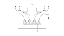
- FIG. 2 is a diagram showing a step (first immersion step) of the film forming method.
- FIG. 2 is a diagram showing one step (ultrasonic wave application step) of the film forming method.
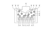
- FIG. 4 is a diagram showing a step (second immersion step) of the film forming method.
- FIG. 2 is a diagram showing a step (polymerization step) of a film forming method.
- 1 is an SEM image showing a thin film formed on a substrate. SEM image showing two thin layers stacked on a substrate. An image of a layered structure in which two types of thin films are stacked horizontally.
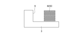
- FIG. 8 is an image diagram showing a state where one of the thin film laminated structures in FIG. 7 has been removed.
- the film formation method of the present disclosure is a film formation method for forming a polymer film on the surface of a substrate in a solution.
- the material of the substrate is not particularly limited, and examples of the substrate material include silicon (Si), silicon oxide (SiO 2 ), silicon nitride (Si 3 N 4 ), and glass epoxy.
- the form of the substrate is not particularly limited.
- Examples of the form of the substrate include a substrate obtained by processing a wafer made of single crystal silicon (Si) in a semiconductor device manufacturing process, a substrate in which an insulating layer such as a silicon oxide film (silicon oxide) and/or a silicon nitride film (silicon nitride) is formed on silicon, and a glass epoxy substrate (glass substrate) for manufacturing flat panel displays.
- the substrate may be in the form of a substrate having a silicon-on-carbon (SOC) film formed thereon, or a silicon-on-glass (SOG) film formed on the SOC film formed on the substrate.
- SOC silicon-on-carbon
- SOG silicon-on-glass
- a polymer film refers to a thin film composed of a polymer of a monomer.
- a polymer film may be a single layer or a laminate of two or more layers.
- a thin film refers to a film with a single layer thickness of 1 ⁇ m or less.
- the film formation method disclosed herein includes a step of immersing a substrate in a first solution containing a polymerization initiator (hereinafter referred to as the first immersion step).
- a substrate 3 is immersed in a solution 2 in which a polymerization initiator 4 is dissolved in an organic solvent in a reaction vessel 1.
- the solution 2 in which a polymerization initiator 4 is dissolved is an example of the first solution.
- the polymerization initiator is not particularly limited, but for example, an organic compound having a chlorine-substituted or bromine-substituted alkyl group at one end and a polymerization initiating group at the other end can be used.
- an organic compound it is preferable to use a sulfonyl chloride compound having a chlorine-substituted or bromine-substituted alkyl group at the end.
- the polymerization initiating group is a chlorosulfonyl group represented by -SO 2 Cl.
- the number of chlorine or bromine substituted on the alkyl group may be one or more.
- the chlorine-substituted alkyl group or bromine-substituted alkyl group and the chlorosulfonyl group there may be a cyclic organic compound such as an aromatic hydrocarbon or alicyclic hydrocarbon, or an arbitrary organic group such as an alkyl group, an imino group, or an ether bond.
- the alkyl group preferably has 1 to 3 carbon atoms, more preferably 1, and may be branched.
- An example of a group having an imino group is N-(2-chloroethyl)sulfamoyl chloride.
- An example of a group having an ether bond is chloromethoxysulfonyl chloride.
- Such sulfonyl chloride compounds include, for example, trichloromethanesulfonyl chloride, tribromomethanesulfonyl chloride, trichloromethylphenylsulfonyl chloride, and other sulfonyl chloride compounds. Among these, it is preferable to use trichloromethanesulfonyl chloride. These compounds may be used alone or in combination of two or more.
- the first solution is a solution in which a polymerization initiator is dissolved in an organic solvent.
- the organic solvent is not particularly limited, but is preferably an aprotic organic solvent from the viewpoint of deactivating radical species generated when irradiated with ultrasonic waves, which will be described later.
- aprotic organic solvents include tetrahydrofuran, dioxane, xylene, toluene, and benzene. Among these, it is preferable to use tetrahydrofuran.
- the concentration of the polymerization initiator in the first solution is preferably 0.1% by mass or more and 20% by mass or less, more preferably 0.5% by mass or more and 10% by mass or less, and even more preferably 1% by mass or more and 5% by mass or less, relative to the organic solvent.
- the substrate is silicon and/or silicon oxide
- the substrate may be pre-treated with ozone before being immersed in the first solution.
- the substrate 3 when the material of the substrate 3 is silicon or silicon oxide, the substrate 3 is exposed to an ozone (O 3 ) atmosphere as a pretreatment before being immersed in the solution 2 in the first immersion step. This results in a state in which polar groups such as hydroxyl groups are bonded to the surface of the substrate 3, and when the first immersion step is performed in this state, the polymerization initiating groups 4 such as chlorosulfonyl groups are more likely to bond to the surface of the substrate 3 to which the polar groups such as hydroxyl groups are bonded.
- O 3 ozone
- the film formation method disclosed herein includes a step of applying ultrasonic waves to a first solution to bond polymerization initiator groups to the surface of the substrate (hereinafter referred to as the ultrasonic application step).
- the ultrasonic application step as shown in FIG. 2, when a substrate 3 is immersed in a solution 2 in which a polymerization initiator is dissolved in a reaction vessel 1 and ultrasonic waves 5 are applied to the solution 2, polymerization initiator groups 4 are bonded to the surface of the substrate 3.
- ultrasound refers to sound waves with frequencies above the audible range (16 kHz to 3000 kHz). Ultrasound is highly directional and does not spread easily, so it is not easily attenuated in liquids. Furthermore, ultrasound has the property of forming localized high temperature and pressure fields in liquids through cavitation (the generation and collapse of bubbles in liquid), which creates micro-flows.
- the surface of the substrate 3 may have a complex uneven pattern. Even in this case, the ultrasonic waves 5 propagate through the solution 2, reach the uneven parts, and cause cavitation. As a result, even if the surface of the substrate 3 has unevenness, a uniform film can be formed in the uneven areas.
- the conditions for irradiating the ultrasonic waves are not particularly limited, but it is preferable to irradiate ultrasonic waves with a frequency of 16 to 3000 kHz and an output of 50 to 600 W for 10 to 90 minutes, for example.
- the polymerization initiating group is a polymerization initiating group derived from a polymerization initiator.
- the polymerization initiating group is the above-mentioned chlorosulfonyl group.
- the polymerization initiator group is preferably one that selectively bonds to the surface of the substrate having a specific polar group. For example, by pre-preparing the surface of the substrate with regions (polar regions) having polar groups such as hydroxyl groups and regions (non-polar regions) not having polar groups, the polymerization initiator group can be bound only to the polar regions on the surface of the substrate.
- the chlorosulfonyl group which is the polymerization initiator group, is highly reactive with hydroxyl groups, and can be selectively bonded to the surface of a substrate to which hydroxyl groups are bonded.
- the film formation method disclosed herein includes a step of immersing a substrate having a surface to which polymerization initiator groups are bonded, in a second solution containing a polymerizable monomer (hereinafter referred to as the second immersion step).
- the second immersion step as shown in FIG. 3, the substrate 3 having a surface to which polymerization initiator groups 4 are bonded is immersed in a solution 2 in which a polymerizable monomer 8 is dissolved in an organic solvent in a reaction vessel 1.
- the solution 2 in which a polymerizable monomer 8 is dissolved is an example of the second solution.
- the second solution may be prepared in the reaction vessel 1 after the ultrasonic application process, and the substrate 3 after the ultrasonic application process may be immersed in the second solution in the reaction vessel 1, or the second solution may be prepared in a reaction vessel other than the reaction vessel 1, and the substrate 3 after the ultrasonic application process may be immersed in the second solution in the other reaction vessel.
- the polymerizable monomer is not particularly limited, but for example, a radical polymerizable monomer having one or more carbon-carbon unsaturated double bonds in one molecule can be used.
- Monomers having one or more carbon-unsaturated double bonds in one molecule include, but are not limited to, styrene, vinyl chloride, methyl methacrylate, dicyclopentadiene dimethacrylate, dicyclopentadiene diacrylate, trimethylolpropane trimethacrylate, trimethylolpropane triacrylate, ethylene glycol dimethacrylate, ethylene glycol diacrylate, diethylene glycol dimethacrylate, diethylene glycol diacrylate, glycerin dimethacrylate, glycerin diacrylate, pentaerythritol triacrylate, and methacrylic anhydride. Of these, ethylene glycol dimethacrylate is preferred.
- the concentration of the polymerizable monomer in the second solution is preferably 0.1% by volume or more and 40% by volume or less, more preferably 0.5% by volume or more and 20% by volume or less, and even more preferably 1% by mass or more and 10% by mass or less, relative to the organic solvent.
- radical active species may be generated on the surface of the substrate to which the polymerization initiator group is bonded.
- the substrate 3 is immersed in a solution 2 in which a polymerizable monomer 8 is dissolved in a reaction vessel 1, and then irradiated with UV light or the like, whereby radicals 7 are generated on the surface of the substrate 3 to which the polymerization initiator group 4 is bonded, and the polymerization initiator group 4 becomes a radical active species.
- the film formation method disclosed herein includes a step (polymerization step) of growing a polymer on the surface of a substrate by a polymerization reaction of a polymerizable monomer initiated by a polymerization initiator group.
- a step polymerization step of growing a polymer on the surface of a substrate by a polymerization reaction of a polymerizable monomer initiated by a polymerization initiator group.
- a polymerization reaction of the polymerizable monomer occurs in a state where a substrate 3 having a polymerization initiator group 4 bonded to its surface is immersed in a solution 2 in which a polymerizable monomer is dissolved in a reaction vessel 1, and a polymer (a polymer of the polymerizable monomer 8) grows on the surface of the substrate 3 in a state where a polymerizable monomer 8 is bonded to the surface of the substrate 3 initiated by the polymerization initiator group 4.
- the polymerization reaction conditions are not particularly limited, but the polymerization time is, for example, 3 minutes to 5 hours, preferably 10 minutes to 3 hours, and more preferably 30 minutes to 2 hours.
- the polymerization temperature is, for example, 3°C to 80°C, preferably 5°C to 60°C, and more preferably 10°C to 40°C.
- the second solution may be stirred or irradiated with the above-mentioned ultrasonic waves.
- the type of polymerization reaction is not particularly limited, but it is preferably a living radical polymerization reaction.
- a living radical polymerization reaction is a reaction that does not involve side reactions that deactivate the ends of the polymer, such as chain transfer reactions and termination reactions. If the polymerization reaction is a living radical polymerization reaction, a polymer of uniform length is obtained, and it is possible to further modify the ends of the polymer, so that the degree of polymerization is easily controlled and a sharp molecular weight distribution is obtained.
- a living radical polymerization reaction it is preferable to convert the polymerization initiating group 4 into a radically active species in the second immersion step, as described above.
- a living radical polymerization reaction can be carried out by irradiating the substrate 3 with UV or the like.
- the film formation method disclosed herein can provide a semiconductor manufacturing process that requires low energy and has a small number of steps by growing a polymer through a polymerization reaction of a polymerizable monomer on the surface of a substrate to which a polymerization initiator group is bonded by applying ultrasound to the first solution. Therefore, the film formation method disclosed herein can be carried out even in a reduced pressure environment such as ALD, and can form a dense film with a small number of steps, thereby contributing to reducing the environmental burden.
- a reduced pressure environment such as ALD
- the polymerizable monomer is a low molecular weight monomer
- a low molecular weight polymerizable monomer refers to a molecule whose size is such that even if the degree of polymerization is about 100, the film thickness when formed is less than tens of nanometers.
- an isotropic and dense film can be formed, making it possible to form a high-quality film.
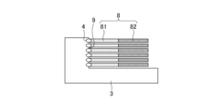
- the ultrasonic application process can bond the polymerization initiator group 4 to the side surface 9 of the substrate 3, and the polymerization process can form a film of polymers of the polymerizable monomer 8 (heterogeneous polymers 81, 82) in the horizontal direction starting from the polymerization initiator group 4 (see Figure 7).
- both of the films of the heterogeneous polymers 81, 82 can become fine thin films on the nanoscale.
- polymer 81 is decomposed by plasma (e.g., oxygen plasma) but polymer 82 is not decomposed by plasma
- plasma e.g., oxygen plasma
- the film of polymer 81 is removed and a film of polymer 82 remains (see FIG. 8). This makes it possible to form a thin film on substrate 3 with a nanoscale minute space between side surface 9 and the remaining polymer 82.
- Example 1 About 40 mL of tetrahydrofuran (THF) as an organic solvent and 1 g of trichloromethanesulfonyl chloride as a polymerization initiator were placed in a 50 mL vial and stirred to prepare a solution in which the polymerization initiator was dissolved in the organic solvent (first solution).
- THF tetrahydrofuran
- first solution trichloromethanesulfonyl chloride
- a silicon (Si) substrate was placed in a vial, which was then placed in an ultrasonic irradiation device containing 1.5 L of water.
- the vial was then irradiated with ultrasonic waves in a nitrogen atmosphere at a frequency of 430 kHz, an output of 80 W, and an irradiation time of 30 minutes.
- Example 1 The cross section of the substrate after drying was observed using a scanning electron microscope (SEM). As a result, it was confirmed that in Example 1, a dense thin film was formed on the substrate surface.
- Example 2 Except for replacing the silicon (Si) substrate with a silicon oxide (SiO 2 ) substrate, the same operation and observation were performed as in Example 1. As a result, it was confirmed that in Example 2, a dense thin film was formed on the substrate surface.
- Example 3 Except for exposing the silicon (Si) substrate to ozone (O 3 ) gas (ozone treatment) before placing it in the vial, the substrate was observed in the same manner as in Example 1. As a result, it was confirmed that a dense thin film was formed on the substrate surface in Example 3.
- Example 4 Except for exposing the silicon oxide (SiO 2 ) substrate to ozone gas (ozone treatment) before placing it in the vial, the substrate was observed in the same manner as in Example 2. As a result, it was confirmed that a dense thin film was formed on the substrate surface in Example 4 (see FIG. 5 ).
- Example 5 After the polymerization reaction, 2 mL of ethylene glycol dimethacrylate was further added as a polymerizable monomer and allowed to stand for 45 minutes (polymerization reaction), and other than that, the same operation and observation were performed as in Example 4. As a result, it was confirmed that a dense thin film was laminated on the surface of the substrate in Example 5 (see FIG. 6).
- Example 5 From Examples 1 to 5, it was found that a dense thin film can be formed on the surface of the substrate by applying ultrasound to the first solution to bond polymerization initiator groups to the surface of the substrate, and then growing a polymer through a polymerization reaction of a polymerizable monomer on the surface of the substrate (see Figure 5). In Example 5, it was also found that multiple dense thin films can be laminated on the surface of the substrate by repeating the polymerization reaction of the polymerizable monomer (see Figure 6).
- a method for forming a polymer film on a surface of a substrate in a solution comprising the steps of: Immersing a substrate in a first solution containing a polymerization initiator; applying ultrasonic waves to the first solution to bond a polymerization initiator group to the surface of the substrate; immersing the substrate having the polymerization initiator group bonded to the surface thereof in a second solution containing a polymerizable monomer; and growing the polymer on the surface of the substrate by a polymerization reaction of the polymerizable monomer starting from the polymerization initiator group.
- Film formation method comprising the steps of: Immersing a substrate in a first solution containing a polymerization initiator; applying ultrasonic waves to the first solution to bond a polymerization initiator group to the surface of the substrate; immersing the substrate having the polymerization initiator group bonded to the surface thereof in a second solution containing a polymerizable monomer; and growing the polymer on the surface of the substrate by a poly
- the polymerization reaction is a living radical polymerization reaction. 3.
- the substrate is silicon or silicon oxide; 5.
Landscapes
- Application Of Or Painting With Fluid Materials (AREA)
- Manufacture Of Macromolecular Shaped Articles (AREA)
- Coating Of Shaped Articles Made Of Macromolecular Substances (AREA)
- Formation Of Insulating Films (AREA)
Abstract
成膜方法は、溶液中で基板の表面にポリマーの膜を形成する成膜方法であって、重合開始剤を含む第1溶液に基板を浸漬する工程と、前記第1溶液に超音波を付与して前記基板の表面に重合開始基を結合させる工程と、前記表面に前記重合開始基が結合した前記基板を、重合性モノマーを含む第2溶液に浸漬する工程と、前記基板の前記表面に、前記重合開始基を起点とした前記重合性モノマーの重合反応により前記ポリマーを成長させる工程と、を有する。
Description
本開示は、成膜方法に関する。
特許文献1には、水素結合基および重合性ジアセチレン基を含む化合物を利用して、基材表面の部分上に自己組織化単分子層(SAM:self-assembled monolayers)を選択的に調製する技術が開示されている。また、特許文献2には、ONON積層構造部のSiN膜をリセスエッチする技術が開示されている。
半導体製造において、特に凹凸のある基板表面に緻密な膜を形成する場合、原子層堆積法(ALD:Atomic Layer Deposition)が採用されているが、この原子層堆積法は、減圧環境下で複数の原料ガスを交互に入れることで行うプロセスであるため、工程数が多く環境負荷が大きい。
本開示は、緻密な膜を形成する際の環境負荷を低減することができる成膜方法を提供する。
本開示の一態様に係る成膜方法は、溶液中で基板の表面にポリマーの膜を形成する成膜方法であって、重合開始剤を含む第1溶液に基板を浸漬する工程と、前記第1溶液に超音波を付与して前記基板の表面に重合開始基を結合させる工程と、前記表面に前記重合開始基が結合した前記基板を、重合性モノマーを含む第2溶液に浸漬する工程と、前記基板の前記表面に、前記重合開始基を起点とした前記重合性モノマーの重合反応により前記ポリマーを成長させる工程と、を有する。
本開示の一態様によれば、緻密な膜を形成する際の環境負荷を低減することができる。
以下、本開示の実施形態について、図面を参照して説明する。なお、各図において共通する部分については、同一の又は対応する符号を付して説明を省略する場合がある。
<基板処理方法>
本開示の成膜方法は、溶液中で基板の表面にポリマーの膜を形成する成膜方法である。
本開示の成膜方法は、溶液中で基板の表面にポリマーの膜を形成する成膜方法である。
基板の材質は、特に限定されない。基板の材質としては、例えば、シリコン(Si)、酸化ケイ素(SiO2)、窒化ケイ素(Si3N4)、ガラスエポキシ等が挙げられる。
基板の形態は、特に限定されない。基板の形態としては、例えば、単結晶シリコン(Si)からなるウェハが半導体デバイス製造工程で加工された基板、シリコンの上にシリコン酸化膜(酸化ケイ素)および/またはシリコン窒化膜(窒化ケイ素)等の絶縁層が形成された基板、フラットパネルディスプレイ製造用のガラスエポキシ基板(ガラス基板)等が挙げられる。
また、基板の形態は、基板上にSOC膜(Silicon-on-Carbon)が形成されたもの、又は基板上に形成されたSOC膜上にさらにSOG膜(Silicon-on-Glass)が形成されたもの等でもよい。
ポリマーの膜は、モノマーの重合体で構成された薄膜を示す。ポリマーの膜は、単層または2層以上の積層体でもよい。本明細書において、薄膜とは、単層の膜厚が1μm以下の膜を示す。
本開示の成膜方法は、重合開始剤を含む第1溶液に基板を浸漬する工程(以下、第1浸漬工程という)を有する。第1浸漬工程では、図1に示すように、反応容器1内で有機溶媒に重合開始剤4を溶解させた溶液2に基板3を浸漬する。ここで、重合開始剤4を溶解させた溶液2は、第1溶液の一例である。
重合開始剤は、特に限定されないが、例えば、塩素置換アルキル基または臭素置換アルキル基を一方の末端に有し、他方の末端に重合開始基を有する有機化合物を使用することができる。このような有機化合物としては、塩素置換アルキル基または臭素置換アルキル基を末端に有するスルホニルクロリド化合物を使用することが好ましい。スルホニルクロリド化合物において、重合開始基は、-SO2Clで表されるクロロスルホニル基である。
重合開始剤がスルホニルクロリド化合物の場合、アルキル基に置換される塩素または臭素の数は、1個以上であればよい。また、塩素置換アルキル基または臭素置換アルキル基とクロロスルホニル基との間には、芳香族炭化水素や脂環式炭化水素などの環式有機化合物またはアルキル基、イミノ基、エーテル結合などの任意の有機基が存在していてもよい。
この場合のアルキル基は、炭素数が1~3が好ましく、より好ましくは1であり、分岐していてもよい。また、イミノ基を有する場合の一例としては、N-(2-chloroethyl)sulfamoyl chloride等が挙げられる。さらに、エーテル結合の場合の一例としては、Chloromethoxysulfonyl Chloride等が挙げられる。
このようなスルホニルクロリド化合物としては、例えば、トリクロロメタンスルホニルクロリド、トリブロモメタンスルホニルクロリド、トリクロロメチルフェニルスルホニルクロリドなどのスルホニルクロリド化合物が挙げられる。これらの中でも、トリクロロメタンスルホニルクロリドを使用することが好ましい。これらは1種のみ用いてもよいし、2種以上を併用してもよい。
第1溶液は、有機溶媒に重合開始剤を溶解させた溶液である。有機溶媒は、特に限定されないが、後述する超音波を照射したときに発生するラジカル種を失活させる観点から、非プロトン系有機溶媒であることが好ましい。このような非プロトン系有機溶媒としては、例えば、テトラヒドロフラン、ジオキサン、キシレン、トルエン、ベンゼンなどが挙げられる。この中でも、テトラヒドロフランを使用することが好ましい。
第1溶液における重合開始剤の濃度は、有機溶媒に対して重合開始剤が0.1質量%以上20質量%以下であることが好ましく、より好ましくは0.5質量%以上10質量%以下であることがより好ましく、さらに好ましくは1質量%以上5質量%以下である。
本開示の成膜方法では、基板がシリコンおよび/または酸化ケイ素の場合、基板を第1溶液に浸漬する前に予め基板をオゾン処理してもよい。
具体的には、基板3の材質がシリコンまたは酸化ケイ素である場合は、第1浸漬工程で溶液2に浸漬する前の前処理として基板3をオゾン(O3)雰囲気に晒す。これにより、基板3の表面に水酸基等の極性基が結合した状態となり、この状態で第1浸漬工程を実施すると、クロロスルホニル基等の重合開始基4が、水酸基等の極性基が結合した基板3の表面に結合しやすくなる。
本開示の成膜方法は、第1溶液に超音波を付与して基板の表面に重合開始基を結合させる工程(以下、超音波付与工程という)を有する。超音波付与工程では、図2に示すように、反応容器1内で重合開始剤を溶解させた溶液2に基板3を浸漬させた状態で、溶液2に超音波5を照射すると、基板3の表面に重合開始基4が結合する。
本明細書において、超音波は、可聴域を超えた周波数(16kHz以上3000kHz以下)の音波を示す。また、超音波は、指向性が高く、広がりにくいため、液体中では減衰しにくい。さらに、超音波は、キャビテーション(液中での気泡生成と圧壊)により、液体中で局所的な高温、高圧場を形成し、ミクロ流動を生じさせる性質を有する。
なお、基板3の表面には複雑な凹凸パターンが形成されていることがある。この場合においても、超音波5が溶液2中を伝わって凹凸部に到達しキャビテーションを生じる。結果として、基板3の表面に凹凸が形成されている場合でも、凹凸のある場所に均一な成膜を行うことができる。
超音波を照射する条件は、特に限定されないが、例えば、周波数が16~3000kHz、出力が50~600Wの超音波を10~90分照射することが好ましい。
重合開始基は、重合開始剤に由来する重合開始基である。例えば、重合開始剤がスルホニルクロリド化合物の場合、重合開始基は、上述のクロロスルホニル基である。
重合開始基は、所定の極性基を持つ基板の表面に選択的に結合するものであることが好ましい。例えば、基板の表面に、水酸基等の極性基を持つ領域(極性領域)と、極性基を持たない領域(非極性領域)を予め設けることで、重合開始基を基板の表面の極性領域のみに結合させることができる。
重合開始剤がスルホニルクロリド化合物の場合、重合開始基であるクロロスルホニル基は、水酸基と反応性が高いため、水酸基が結合した基板の表面に選択的に結合させることができる。
本開示の成膜方法は、表面に重合開始基が結合した基板を、重合性モノマーを含む第2溶液に浸漬する工程(以下、第2浸漬工程という)を有する。第2浸漬工程では、図3に示すように、基板3の表面に重合開始基4が結合した状態で、反応容器1内で有機溶媒に重合性モノマー8を溶解させた溶液2に基板3を浸漬する。ここで、重合性モノマー8を溶解させた溶液2は、第2溶液の一例である。
なお、第2溶液は、超音波付与工程後の反応容器1内で調製し、超音波付与工程後の基板3を反応容器1内で第2溶液に浸漬してもよいし、反応容器1とは別の反応容器で第2溶液を調製し、超音波付与工程後の基板3を該別の反応容器内で第2溶液に浸漬してもよい。
重合性モノマーは、特に限定されないが、例えば、1分子中に1つ以上の炭素不飽和二重結合を有するラジカル重合性モノマーを使用することができる。
1分子中に1つ以上の炭素不飽和二重結合を有する単量体としては、特に限定されないが、例えば、スチレン、塩化ビニル、メチルメタクリレート、ジシクロペンタジエンジメタクリレート、ジシクロペンタジエンジアクリレート、トリメチロールプロパントリメタクリレート、トリメチロールプロパントリアクリレート、エチレングリコールジメタクリレート、エチレングリコールジアクリレート、ジエチレングリコールジメタクリレート、ジエチレングリコールジアクリレート、グリセリンジメタクリレート、グリセリンジアクリレート、ペンタエリスリトールトリアクリレート、及び無水メタクリル酸等が挙げられる。これらの中でもエチレングリコールジメタクリレートが好ましい。
第2溶液における重合性モノマーの濃度は、有機溶媒に対して重合性モノマーが0.1体積%以上40体積%以下であることが好ましく、より好ましくは0.5体積%以上20体積%以下、さらに好ましくは1質量%以上10質量%以下である。
また、第2浸漬工程では、重合開始基が結合する基板の表面にラジカル活性種を発生させてもよい。具体的には、図3に示すように、反応容器1内で重合性モノマー8を溶解させた溶液2に基板3を浸漬した状態で、基板3にUV等を照射することにより、重合開始基4が結合する基板3の表面にラジカル7が発生し、重合開始基4がラジカル活性種になる。
本開示の成膜方法は、基板の表面に、重合開始基を起点とした重合性モノマーの重合反応によりポリマーを成長させる工程(重合工程)を有する。重合工程では、図4に示すように、反応容器1内で重合性モノマーを溶解させた溶液2に、表面に重合開始基4が結合した基板3を浸漬させた状態で、重合性モノマーの重合反応が起こり、重合開始基4を起点として基板3の表面に重合性モノマー8が結合した状態で、基板3の表面でポリマー(重合性モノマー8の重合体)が成長する。
重合反応の条件は、特に限定されないが、重合時間は、例えば、3分以上5時間以下であり、好ましくは10分以上3時間以下、より好ましくは30分以上2時間以下である。また、重合温度は、例えば、3℃以上80℃以下であり、好ましくは5℃以上60℃以下、より好ましくは10℃以上40℃以下である。また、重合反応時は第2溶液を撹拌してもよいし、上述の超音波を照射してもよい。
重合反応の種類は、特に限定されないが、リビングラジカル重合反応であることが好ましい。リビングラジカル重合反応とは、連鎖移動反応や停止反応などポリマーの末端を失活させる副反応を伴わない反応である。重合反応がリビングラジカル重合反応であると、長さのそろったポリマーが得られ、またそのポリマーの末端に再度ポリマーを修飾することが可能であり、重合度が制御しやすい、シャープな分子量分布が得られる。
重合工程において、リビングラジカル重合反応を行うには、上述のように、第2浸漬工程で重合開始基4をラジカル活性種にすることが好ましい。また、重合工程において、基板3にUV等を照射することにより、リビングラジカル重合反応を行うことができる。
本開示の成膜方法では、上述のように、第1溶液に超音波を付与して重合開始基を結合させた基板の表面に、重合性モノマーの重合反応によりポリマーを成長させることで、低エネルギーで、工程数が少ない半導体製造プロセスを提供することができる。そのため、本開示の成膜方法は、ALDのような減圧環境下でなくても実施可能であり、少ない工程数で緻密な膜を形成できるので、環境負荷の低減に寄与する。
また、重合性モノマーが低分子量のモノマーであっても、数十nm程度の寸法の溝や穴の形状を有する微細なパターンの表面あるいは内部への成膜が可能である。なお、重合性の低分子量のモノマーとは、重合度が100程度になっても成膜時の膜厚が数十nmに満たない大きさの分子を示す。さらに、低分子量のモノマーを重合させることで、等方性で緻密な膜を形成することができるため、高品質な成膜が可能である。
具体的には、超音波付与工程により、基板3の側面9に、重合開始基4を結合させることができ、重合工程により、重合開始基4を起点に水平方向に重合性モノマー8の重合体(異種のポリマー81、82)の膜を形成することができる(図7参照)。また、異種のポリマー81、82の膜は、いずれもナノスケールの微細な薄膜となり得る。
さらに、ポリマー81はプラズマ(例えば、酸素プラズマ)によって分解され、ポリマー82はプラズマで分解されないように、重合性モノマーを選択することで、基板3にプラズマを照射すると、ポリマー81の膜が除去され、ポリマー82の膜が残る(図8参照)。これにより、基板3に側面9と残存するポリマー82との間にナノスケールの微小なスペースを持つ薄膜を形成することができる。
以下、本開示の成膜方法について、さらに実施例を用いて説明する。
[実施例1]
容量50mLのバイアル瓶に、有機溶媒としてテトラヒドロフラン(THF)約40mLと、重合開始剤としてトリクロロメタンスルホニルクロリド1gを入れて攪拌し、有機溶媒に重合開始剤が溶解する溶液(第1溶液)を調製した。
容量50mLのバイアル瓶に、有機溶媒としてテトラヒドロフラン(THF)約40mLと、重合開始剤としてトリクロロメタンスルホニルクロリド1gを入れて攪拌し、有機溶媒に重合開始剤が溶解する溶液(第1溶液)を調製した。
バイアル瓶に、シリコン(Si)基板を入れ、水1.5Lを入れた超音波照射装置内にバイアル瓶をセットして、窒素雰囲気下で、周波数430kHz、出力80W、照射時間30分の条件で、バイアル瓶に超音波を照射した。
超音波の照射後のバイアル瓶内に、重合性モノマーとしてエチレングリコールジメタクリレート2mLを入れ(第2溶液)、45分間静置(重合反応)した後、バイアル瓶から取り出した基板をTHFで洗浄し乾燥させた。
乾燥後の基板の断面を走査電子顕微鏡(SEM:Scanning Electron Microscope)で観察した。その結果、実施例1では、基板表面に緻密な薄膜が形成されていることを確認した。
[実施例2]
シリコン(Si)基板を酸化ケイ素(SiO2)基板に替えた以外は、実施例1と同様に操作し、観察した。その結果、実施例2では、基板表面に緻密な薄膜が形成されていることを確認した。
シリコン(Si)基板を酸化ケイ素(SiO2)基板に替えた以外は、実施例1と同様に操作し、観察した。その結果、実施例2では、基板表面に緻密な薄膜が形成されていることを確認した。
[実施例3]
シリコン(Si)基板を、バイアル瓶に入れる前に予めオゾン(O3)ガスに晒した(オゾン処理した)以外は、実施例1と同様に操作し、観察した。その結果、実施例3では、基板表面に緻密な薄膜が形成されていることを確認した。
シリコン(Si)基板を、バイアル瓶に入れる前に予めオゾン(O3)ガスに晒した(オゾン処理した)以外は、実施例1と同様に操作し、観察した。その結果、実施例3では、基板表面に緻密な薄膜が形成されていることを確認した。
[実施例4]
酸化ケイ素(SiO2)基板を、バイアル瓶に入れる前に予めオゾンガスに晒した(オゾン処理)以外は、実施例2と同様に操作し、観察した。その結果、実施例4では、基板表面に緻密な薄膜が形成されていることを確認した(図5参照)。
酸化ケイ素(SiO2)基板を、バイアル瓶に入れる前に予めオゾンガスに晒した(オゾン処理)以外は、実施例2と同様に操作し、観察した。その結果、実施例4では、基板表面に緻密な薄膜が形成されていることを確認した(図5参照)。
[実施例5]
重合反応後、さらに重合性モノマーとしてエチレングリコールジメタクリレート2mLを入れ、45分間静置(重合反応)した以外は、実施例4と同様に操作し、観察した。その結果、実施例5では、基板表面に緻密な薄膜が積層されていることを確認した(図6参照)。
重合反応後、さらに重合性モノマーとしてエチレングリコールジメタクリレート2mLを入れ、45分間静置(重合反応)した以外は、実施例4と同様に操作し、観察した。その結果、実施例5では、基板表面に緻密な薄膜が積層されていることを確認した(図6参照)。
実施例1~5より、第1溶液に超音波を付与して重合開始基を結合させた基板の表面に、重合性モノマーの重合反応によりポリマーを成長させることで、基板の表面に緻密な薄膜を形成できることが分かった(図5参照)。また、実施例5では、重合性モノマーの重合反応を繰り返すことで、基板表面に複数の緻密な薄膜を積層できることが分かった(図6参照)。
以上に開示された実施形態は、例えば、以下の態様を含む。
(付記1)
溶液中で基板の表面にポリマーの膜を形成する成膜方法であって、
重合開始剤を含む第1溶液に基板を浸漬する工程と、
前記第1溶液に超音波を付与して前記基板の表面に重合開始基を結合させる工程と、
前記表面に前記重合開始基が結合した前記基板を、重合性モノマーを含む第2溶液に浸漬する工程と、
前記基板の前記表面に、前記重合開始基を起点とした前記重合性モノマーの重合反応により前記ポリマーを成長させる工程と、を有する、
成膜方法。
溶液中で基板の表面にポリマーの膜を形成する成膜方法であって、
重合開始剤を含む第1溶液に基板を浸漬する工程と、
前記第1溶液に超音波を付与して前記基板の表面に重合開始基を結合させる工程と、
前記表面に前記重合開始基が結合した前記基板を、重合性モノマーを含む第2溶液に浸漬する工程と、
前記基板の前記表面に、前記重合開始基を起点とした前記重合性モノマーの重合反応により前記ポリマーを成長させる工程と、を有する、
成膜方法。
(付記2)
前記重合開始基は、所定の極性基を持つ基板の表面に選択的に結合する、
付記1に記載の成膜方法。
前記重合開始基は、所定の極性基を持つ基板の表面に選択的に結合する、
付記1に記載の成膜方法。
(付記3)
前記重合反応は、リビングラジカル重合反応である、
付記1または2に記載の成膜方法。
前記重合反応は、リビングラジカル重合反応である、
付記1または2に記載の成膜方法。
(付記4)
前記重合開始基が結合する前記基板の前記表面にラジカル活性種を発生させる、
付記1乃至3のいずれか一項に記載の成膜方法。
前記重合開始基が結合する前記基板の前記表面にラジカル活性種を発生させる、
付記1乃至3のいずれか一項に記載の成膜方法。
(付記5)
前記基板は、シリコンまたは酸化ケイ素であり、
前記基板を前記第1溶液に浸漬する前に予め前記基板をオゾン処理する、付記1乃至4のいずれか1項に記載の成膜方法。
前記基板は、シリコンまたは酸化ケイ素であり、
前記基板を前記第1溶液に浸漬する前に予め前記基板をオゾン処理する、付記1乃至4のいずれか1項に記載の成膜方法。
(付記6)
前記基板の前記表面には凹凸が形成されている、付記1乃至5のいずれか1項に記載の成膜方法。
前記基板の前記表面には凹凸が形成されている、付記1乃至5のいずれか1項に記載の成膜方法。
以上、本開示の実施形態について説明したが、本開示はこれらの実施形態に限定されることなく、特許請求の範囲に記載された開示の範囲内において、種々の変形、変更が可能である。
本出願は、2023年4月12日に出願された日本国特許出願2023-065122号に基づく優先権を主張するものであり、その全内容をここに援用する。
1 反応容器
2 溶液
3 基板
4 重合開始剤(重合開始基)
5 超音波
6 UV
7 ラジカル
8 重合性モノマー
81 ポリマー
82 ポリマー
9 側面
2 溶液
3 基板
4 重合開始剤(重合開始基)
5 超音波
6 UV
7 ラジカル
8 重合性モノマー
81 ポリマー
82 ポリマー
9 側面
Claims (6)
- 溶液中で基板の表面にポリマーの膜を形成する成膜方法であって、
重合開始剤を含む第1溶液に基板を浸漬する工程と、
前記第1溶液に超音波を付与して前記基板の表面に重合開始基を結合させる工程と、
前記表面に前記重合開始基が結合した前記基板を、重合性モノマーを含む第2溶液に浸漬する工程と、
前記基板の前記表面に、前記重合開始基を起点とした前記重合性モノマーの重合反応により前記ポリマーを成長させる工程と、を有する、
成膜方法。 - 前記重合開始基は、所定の極性基を持つ基板の表面に選択的に結合する、
請求項1に記載の成膜方法。 - 前記重合反応は、リビングラジカル重合反応である、
請求項1に記載の成膜方法。 - 前記重合開始基が結合する前記基板の前記表面にラジカル活性種を発生させる、
請求項1に記載の成膜方法。 - 前記基板は、シリコンまたは酸化ケイ素であり、
前記基板を前記第1溶液に浸漬する前に予め前記基板をオゾン処理する、請求項1に記載の成膜方法。 - 前記基板の前記表面には凹凸が形成されている、請求項1乃至5のいずれか1項に記載の成膜方法。
Applications Claiming Priority (2)
| Application Number | Priority Date | Filing Date | Title |
|---|---|---|---|
| JP2023065122 | 2023-04-12 | ||
| JP2023-065122 | 2023-04-12 |
Publications (1)
| Publication Number | Publication Date |
|---|---|
| WO2024214601A1 true WO2024214601A1 (ja) | 2024-10-17 |
Family
ID=93059252
Family Applications (1)
| Application Number | Title | Priority Date | Filing Date |
|---|---|---|---|
| PCT/JP2024/013678 Ceased WO2024214601A1 (ja) | 2023-04-12 | 2024-04-02 | 成膜方法 |
Country Status (2)
| Country | Link |
|---|---|
| TW (1) | TW202442704A (ja) |
| WO (1) | WO2024214601A1 (ja) |
Citations (4)
| Publication number | Priority date | Publication date | Assignee | Title |
|---|---|---|---|---|
| JP2008104909A (ja) * | 2006-10-23 | 2008-05-08 | Fujifilm Corp | 金属膜付基板の作製方法、金属膜付基板、金属パターン材料の作製方法、金属パターン材料 |
| JP2010168468A (ja) * | 2009-01-22 | 2010-08-05 | Jgc Catalysts & Chemicals Ltd | 重合開始基付き無機酸化物粒子並びにその製造方法、および該無機酸化物粒子を用いて得られる高分子修飾無機酸化物粒子並びにその製造方法 |
| JP2018001087A (ja) * | 2016-06-30 | 2018-01-11 | 関西ペイント株式会社 | 親水性被膜形成方法 |
| WO2018225693A1 (ja) * | 2017-06-06 | 2018-12-13 | 独立行政法人国立高等専門学校機構 | ポリマーブラシ層の形成方法 |
-
2024
- 2024-04-02 WO PCT/JP2024/013678 patent/WO2024214601A1/ja not_active Ceased
- 2024-04-10 TW TW113113293A patent/TW202442704A/zh unknown
Patent Citations (4)
| Publication number | Priority date | Publication date | Assignee | Title |
|---|---|---|---|---|
| JP2008104909A (ja) * | 2006-10-23 | 2008-05-08 | Fujifilm Corp | 金属膜付基板の作製方法、金属膜付基板、金属パターン材料の作製方法、金属パターン材料 |
| JP2010168468A (ja) * | 2009-01-22 | 2010-08-05 | Jgc Catalysts & Chemicals Ltd | 重合開始基付き無機酸化物粒子並びにその製造方法、および該無機酸化物粒子を用いて得られる高分子修飾無機酸化物粒子並びにその製造方法 |
| JP2018001087A (ja) * | 2016-06-30 | 2018-01-11 | 関西ペイント株式会社 | 親水性被膜形成方法 |
| WO2018225693A1 (ja) * | 2017-06-06 | 2018-12-13 | 独立行政法人国立高等専門学校機構 | ポリマーブラシ層の形成方法 |
Also Published As
| Publication number | Publication date |
|---|---|
| TW202442704A (zh) | 2024-11-01 |
Similar Documents
| Publication | Publication Date | Title |
|---|---|---|
| KR100930966B1 (ko) | 블록공중합체의 나노구조와 일치하지 않는 형태의 표면패턴상에 형성되는 블록공중합체의 나노구조체 및 그 제조방법 | |
| KR101350072B1 (ko) | 서브 리소그래픽 패터닝을 위해 블록 공중합체 자기 조립을 사용하는 방법 | |
| Vauthier et al. | Interfacial thermoreversible chemistry on functional coatings: A focus on the Diels–Alder reaction | |
| JP2010058403A (ja) | 高分子膜および積層体 | |
| Moni et al. | Ultrathin and conformal initiated chemical-vapor-deposited layers of systematically varied surface energy for controlling the directed self-assembly of block copolymers | |
| US9097979B2 (en) | Block copolymer-based mask structures for the growth of nanopatterned polymer brushes | |
| Sparnacci et al. | Thermal stability of functional P (Sr-MMA) random copolymers for nanolithographic applications | |
| TWI887304B (zh) | 非硫醇類基於氮之疏水性高分子刷材料及其用於基板表面修飾之用途 | |
| US9417520B2 (en) | Methods of patterning block copolymer layers and patterned structures | |
| KR20200088881A (ko) | 플래너 폴리머 스택을 제조하는 방법 | |
| CN105829239A (zh) | 用于对使用基于苯乙烯和基于甲基丙烯酸甲酯的未经结构化的嵌段共聚物的嵌段共聚物膜进行纳米结构化的工艺、以及经纳米结构化的嵌段共聚物膜 | |
| CN105051870A (zh) | 形成图案的方法 | |
| Kim et al. | Formation of Various Polymeric Films via Surface‐Initiated ARGET ATRP on Silicon Substrates | |
| Kim et al. | Recent advances in block copolymer self‐assembly: From the lowest to the highest | |
| WO2024214601A1 (ja) | 成膜方法 | |
| JP7480484B2 (ja) | 樹脂組成物 | |
| CN115793410A (zh) | 一种结构可控纳米颗粒微阵列的制备方法 | |
| JP7389910B2 (ja) | 基板をナノ構造化するための方法 | |
| CN110016154A (zh) | 一种光子带隙可调型聚乙烯亚胺功能化光子晶体薄膜的制备 | |
| Son et al. | Photo-cleavable perfluoroalkylated copolymers for tailoring quantum dot thin films | |
| JP2010132868A (ja) | アリールアジド基を有する高分子重合開始剤およびこれを利用した環式オレフィン共重合体表面改質方法。 | |
| EP0344799B1 (en) | Selectively permeable film and process for producing the same | |
| Chen et al. | Ferritin immobilization on patterned poly (2-hydroxyethyl methacrylate) brushes on silicon surfaces from colloid system | |
| CN1772797A (zh) | 共价层层自组装在平面基底上构建聚合物薄膜的方法 | |
| JP2023509016A (ja) | コントラスト層を形成するためのプレポリマー組成物及び界面材料を構造化するための方法 |
Legal Events
| Date | Code | Title | Description |
|---|---|---|---|
| 121 | Ep: the epo has been informed by wipo that ep was designated in this application |
Ref document number: 24788628 Country of ref document: EP Kind code of ref document: A1 |
|
| NENP | Non-entry into the national phase |
Ref country code: DE |
|
| 122 | Ep: pct application non-entry in european phase |
Ref document number: 24788628 Country of ref document: EP Kind code of ref document: A1 |