WO2024214454A1 - 回転体の防振構造 - Google Patents
回転体の防振構造 Download PDFInfo
- Publication number
- WO2024214454A1 WO2024214454A1 PCT/JP2024/009239 JP2024009239W WO2024214454A1 WO 2024214454 A1 WO2024214454 A1 WO 2024214454A1 JP 2024009239 W JP2024009239 W JP 2024009239W WO 2024214454 A1 WO2024214454 A1 WO 2024214454A1
- Authority
- WO
- WIPO (PCT)
- Prior art keywords
- head member
- rotating body
- coolant
- weight member
- weight
- Prior art date
- Legal status (The legal status is an assumption and is not a legal conclusion. Google has not performed a legal analysis and makes no representation as to the accuracy of the status listed.)
- Ceased
Links
Images



Classifications
-
- B—PERFORMING OPERATIONS; TRANSPORTING
- B23—MACHINE TOOLS; METAL-WORKING NOT OTHERWISE PROVIDED FOR
- B23B—TURNING; BORING
- B23B29/00—Holders for non-rotary cutting tools; Boring bars or boring heads; Accessories for tool holders
- B23B29/02—Boring bars
- B23B29/022—Boring bars with vibration reducing means
-
- B—PERFORMING OPERATIONS; TRANSPORTING
- B23—MACHINE TOOLS; METAL-WORKING NOT OTHERWISE PROVIDED FOR
- B23B—TURNING; BORING
- B23B2250/00—Compensating adverse effects during turning, boring or drilling
- B23B2250/12—Cooling and lubrication
-
- B—PERFORMING OPERATIONS; TRANSPORTING
- B23—MACHINE TOOLS; METAL-WORKING NOT OTHERWISE PROVIDED FOR
- B23B—TURNING; BORING
- B23B2250/00—Compensating adverse effects during turning, boring or drilling
- B23B2250/16—Damping of vibrations
-
- B—PERFORMING OPERATIONS; TRANSPORTING
- B23—MACHINE TOOLS; METAL-WORKING NOT OTHERWISE PROVIDED FOR
- B23B—TURNING; BORING
- B23B2270/00—Details of turning, boring or drilling machines, processes or tools not otherwise provided for
- B23B2270/06—Use of elastic deformation
-
- B—PERFORMING OPERATIONS; TRANSPORTING
- B23—MACHINE TOOLS; METAL-WORKING NOT OTHERWISE PROVIDED FOR
- B23B—TURNING; BORING
- B23B29/00—Holders for non-rotary cutting tools; Boring bars or boring heads; Accessories for tool holders
- B23B29/03—Boring heads
- B23B29/034—Boring heads with tools moving radially, e.g. for making chamfers or undercuttings
- B23B29/03403—Boring heads with tools moving radially, e.g. for making chamfers or undercuttings radially adjustable before starting manufacturing
Definitions
- the present invention relates to a vibration-proof structure for a rotating body that prevents vibration during rotary processing.
- the tool holder which has the cutting blade fixed to the tip, is attached to the machine tool in a cantilevered state, so there is a problem that if the tool holder generates chatter vibrations during cutting, in which the tool holder is rotated to cut the metal, the machining accuracy will decrease.
- Patent Document 1 discloses a tool shaft vibration isolation device in which a weight member (referred to as a "damper” in the document) is disposed in a hollow space formed inside a rotating body (referred to as a "rod” in the document).
- the weight member is vibrated to cancel out chatter vibrations that occur during cutting processing with a cutting tool (referred to as a "cutter head” in the document).
- the weight member absorbs the energy of the chatter vibrations, and the tool shaft vibration isolation device can improve processing accuracy.
- the cutting tool is positioned away from the weight member in the direction of the rotation axis, so when the chatter vibration generated during cutting processing by the cutting tool is large, the weight member may not be able to sufficiently attenuate the chatter vibration.
- the vibration-proof structure for a rotating body is characterized by comprising a cylindrical rotating body having a rotation axis and an opening at one end in a direction along the rotation axis, and a hollow portion extending from the opening along the rotation axis, a weight member disposed in the hollow portion, a plurality of elastic members for holding the weight member, and a head member that closes the opening and is connected to the rotating body coaxially with the rotation axis, the opening and the hollow portion having a circular cross section centered on the rotation axis, the weight member being cylindrical and disposed coaxially with the rotation axis, the head member being configured so that a cutting tool can be attached to the side opposite to the side connected to the rotating body, and the weight member having a protruding portion that protrudes toward the head member beyond the outer circumferential boundary between the rotating body and the head member.
- the weight member disposed in the hollow portion of the rotating body is held by a plurality of elastic members and has a protruding portion that protrudes toward the head member side from the boundary between the outer periphery of the rotating body and the head member. Therefore, by inserting the protruding portion of the weight member disposed in the hollow portion of the rotating body into the head member, for example, the weight member can be disposed in a position close to the cutting tool attached to the head member. This allows the rotating body to effectively dampen vibrations generated during cutting processing by the weight member that is close to the cutting tool.
- the protruding portion of the weight member in the head member, the storage space for the weight member is expanded in the head member. This ensures a long storage space for the weight member in the direction of the rotation axis. As a result, a heavy weight member can be disposed in the rotating body and the head member, and the vibration damping effect of the weight member can be enhanced.
- Another characteristic feature is that the protrusion of the weight member protrudes toward the head member beyond the opening, and at least one of the multiple elastic members is positioned so as to abut both the outer circumferential surface of the protrusion and the head member.
- the protruding portion of the weight member protrudes toward the head member from the opening of the rotating body, so the weight member can be positioned closer to the cutting tool attached to the head member.
- This allows the rotating body to more effectively dampen vibrations generated during cutting by the weight member close to the cutting member.
- the vibration damping effect of the weight member can be obtained early.
- at least one of the multiple elastic members is positioned so as to abut both the outer peripheral surface of the protruding portion and the head member, so that vibrations generated during cutting can be damped by the weight member.
- the protruding portion is held by using the elastic member on the head member side, the weight member can be held securely.
- the cutting tool further includes a coolant pipe that passes through the center of the weight member in the axial direction and through which coolant is supplied to the cutting tool, and the head member is provided at a position continuous with the end of the coolant pipe and has a coolant reservoir space with a diameter larger than the inner diameter of the coolant pipe.
- the head member has a coolant reservoir space at a position connected to the end of the coolant pipe, and the coolant reservoir space has a diameter larger than the inner diameter of the coolant pipe. Therefore, the rotating body can smoothly supply coolant to the cutting tool through the coolant reservoir space.
- the head member has a circulation section that extends radially from the coolant reservoir space and circulates the coolant to supply it to the cutting tool.
- the head member has a circulation portion that extends radially from the coolant reservoir space and allows the coolant to flow, so that the coolant can be smoothly supplied to the cutting tool via the circulation portion.
- the circulation portion is formed, for example, by drilling holes from the outer surface of the head member toward the coolant reservoir space.
- the coolant reservoir space connected to the circulation portion has a larger diameter than the inner diameter of the coolant pipe, when the circulation portion is formed from the outer surface of the head member, the circulation portion can be easily connected to the coolant reservoir space. As a result, the circulation portion can be easily formed in the head member.
- the head member has a plurality of components arranged along the axial direction of the rotor, and the protruding portion protrudes into at least one of the plurality of components that is closest to the rotor.
- the head member has multiple components, so the function and shape of the head member can be easily changed by simply replacing some of the components of the head member.
- the protruding portion of the weight member protrudes into at least the component member that is closest to the rotating body among the multiple components. Therefore, even with this configuration, the rotating body can reliably position the weight member in a position close to the cutting tool attached to the head member.
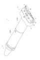
- FIG. 1 is a perspective view of a tool holder equipped with a vibration-proof structure of a first embodiment.
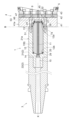
- 1 is a vertical sectional view of a tool holder equipped with a vibration-proof structure of a first embodiment.
- FIG. FIG. 3 is an enlarged view of the enclosed portion A in FIG. 2 .
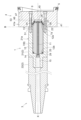
- FIG. 4 is a vertical cross-sectional view showing a modified example of the first embodiment.
- FIG. 11 is a vertical sectional view of a tool holder provided with a vibration-proof structure of a second embodiment.
- FIG. 11 is a vertical sectional view of a tool holder provided with a vibration-proof structure of another embodiment.
- First Embodiment 1 to 3 show a tool holder 1 with a vibration-proof structure according to the present invention.
- This tool holder 1 is for boring and has a cylindrical long body 2 (one example of a rotating body), a tapered shank portion 3 gripped by a spindle (not shown) of a machine tool, and a head member 4 including a cutting tool 5.
- the body 2 is composed of a first body 21 and a second body 22 that are continuous along the rotation axis X of the tool holder 1.
- the first body 21 is disposed on the head member 4 side (hereinafter, the head member 4 side relatively to the tool holder 1 is also referred to as the "tip side”), and the second body 22 is disposed on the shank portion 3 side (hereinafter, the shank portion 3 side relatively to the tool holder 1 is also referred to as the "base end side”).
- the tip side of the first body 21 is provided with a tip portion 23 having a smaller diameter than the outer periphery 21a, which can be disposed in a recess 44 (see FIG. 3) of a first member 41 of the head member 4 described later.
- the head member 4 is configured so that a cutting tool 5 can be attached to the side (tip side) opposite to the side connected to the first body 21 .
- the tool holder 1 has a rotation axis X, an opening 7a provided at one end of the first body 21 on the tip side in the direction along the rotation axis X, and a hollow portion 7 provided continuous with the opening 7a on the base end side along the rotation axis X.
- the hollow portion 7 is formed by an axial hole 8 having an opening 7a on the tip side of the first body 21.
- the first body 21 is configured in a cylindrical shape by having the hollow portion 7.
- the opening 7a and hollow portion 7 provided in the first body 21 have a circular cross section centered on the rotation axis X.
- a weight member 12 is disposed in the hollow portion 7.
- the weight member 12 is made of a material with appropriate damping characteristics, such as a metal material with a high specific gravity such as tungsten.
- the weight member 12 is cylindrical and disposed so as to be coaxial with the rotation axis X.
- the weight member 12 is held by a number of elastic members 24, 25 disposed on the outer periphery (outer periphery surface).
- the elastic members 24, 25 are constituted by O-rings formed of an elastic material.
- a coolant supply passage 15 for supplying a coolant such as cutting oil to the cutting tool 5 is formed coaxially with the rotation axis X from the shank portion 3 to the second body 22.
- a coolant pipe 11 is connected to the tip side of the coolant supply passage 15 and passes through the hollow portion 7 coaxially with the rotation axis X.
- the coolant pipe 11 is fitted inside so as to pass through the weight member 12. Coolant flows through the coolant supply passage 15 and the inside of the coolant pipe 11.
- the head member 4 closes the opening 7a and is connected to the tool holder 1 coaxially with the rotation axis X.
- the head member 4 has a first member 41, a second member 42, and a third member 43 from the base end side along the rotation axis X.
- a part of the weight member 12 protrudes from the opening 7a of the hollow portion 7.
- the coolant pipe 11 protrudes further toward the tip side than the weight member 12.
- the first member 41 has a recess 44, into which the weight member 12 is inserted.
- the part of the weight member 12 inserted into the recess 44 in other words, the part protruding toward the head member 4 side from the boundary B of the outer periphery (21a, 41a) between the first main body 21 of the main body 2 and the first member 41 of the head member 4, is referred to as the protruding part 13.
- the first member 41 of the head member 4 closes the opening 7a and is connected to the first main body 21 of the tool holder 1 coaxially with the rotation axis X.
- a cutting tool 5 is attached to the tip side of the third member 43. As shown in Figures 1 and 2, in this embodiment, two cutting tools 5 are arranged at positions that are point symmetric with respect to the rotation axis X.
- the number of cutting tools 5 attached to the head member 4 may be one or three or more.
- FIG. 3 is an enlarged view of the enclosed portion A (portion surrounded by a two-dot chain line) of the tool holder 1 shown in FIG. 2.
- the recess 44 has a first recess 44a, a second recess 44b, a third recess 44c, and a fourth recess 44d in this order from the tip side to the base side. That is, the inner diameter increases in the order of the first recess 44a, the second recess 44b, the third recess 44c, and the fourth recess 44d.
- the plug member 9 is disposed in the second recess 44b.
- the protruding portion 13 of the weight member 12 is disposed in the third recess 44c.
- the protruding portion 13 and the tip portion 23 of the first body 21 are disposed in the fourth recess 44d.
- the tip of the coolant pipe 11 is held by a plug member 9.
- the plug member 9 has a through hole 17 through which the coolant flows.
- the coolant pipe 11 is connected to the coolant storage space 45 via the through hole 17 formed in the plug member 9.
- the through hole 17 is formed with a first hole 17a having the same shape as the inner diameter of the coolant pipe 11 and a second hole 17b having the same shape as the outer shape of the coolant pipe 11, which are formed continuously.
- the base end side of the coolant pipe 11 is pressed toward the head member 4 by the coupling member 14 fitted into the coolant supply passage 15 of the first body 21 (see FIG. 2), and the tip side of the coolant pipe 11 is held in position by abutting against the step between the first hole 17a and the second hole 17b of the plug member 9.
- the seal material 26 fitted into the inner surface of the second hole 17b of the plug member 9 abuts against the outer surface of the coolant pipe 11.
- the coolant pipe 11 and the weight member 12 are held in position by joining the first member 41 of the head member 4 to the first body 21. Specifically, first, the coolant pipe 11 and the weight member 12 to which the elastic members 24, 25 are attached are inserted into the hollow portion 7 of the first body 21. Next, the plug member 9 to which the sealing material 27 is attached on the outer circumferential surface is placed in the second recess 44b of the first member 41. After that, the tip side of the first body 21 is fitted into the recess 44 of the first member 41 and the position is adjusted. At this time, the tip side of the coolant pipe 11 abuts against the step between the first hole 17a and the second hole 17b of the plug member 9.
- the plug member 9 is configured with a larger diameter than the first recess 44a, the plug member 9 is not placed in the first recess 44a. Therefore, when the first member 41 of the head member 4 is connected to the first body 21, a coolant reservoir space 45 partitioned by the plug member 9 is formed in the first recess 44a.
- the coolant reservoir space 45 temporarily stores the coolant that has flowed through the coolant supply passage 15 and the coolant pipe 11.
- the weight member 12 has, in the direction along the rotation axis X, a base end 12b on the shank portion 3 side and a tip end 12a on the protruding portion 13 side.
- the base end 12b and tip end 12a of the weight member 12 are formed with a smaller diameter than other portions.
- the base end 12b is disposed in the hollow portion 7 of the first body 21, while the tip end 12a protrudes from the opening 7a of the hollow portion 7 to the head member 4 side and is included in the protruding portion 13.
- the base end 12b of the weight member 12 is held by a ring-shaped elastic member 24 disposed between the hollow portion 7 of the first body 21 and the tip end 12a is held by a ring-shaped elastic member 25 disposed between the hollow portion 7 of the first body 21 and the tip end 12a. That is, at least one of the multiple elastic members 24, 25 (elastic member 24) is arranged so as to abut against both the outer circumferential surface of the protrusion 13 (the outer circumferential surface of the tip end 12a) and the inner circumferential surface of the first member 41 (head member 4).
- the elastic members 24, 25 are arranged between the weight member 12 and the first member 41, or between the weight member 12 and the first body 21, and a predetermined elastic force acts on the weight member 12.
- the elastic members 24, 25 are not limited to being ring-shaped as long as they can hold the weight member 12 in the hollow portion 7.
- the elastic members 24, 25 may be arranged, for example, in a dispersed manner on the outer periphery of the weight member 12 to hold the weight member 12 in the hollow portion 7.
- FIG. 2 shows an example in which two elastic members 24, 25 are arranged on both ends along the rotation axis X on the outer surface side of the weight member 12, but another elastic member may be arranged in the middle of the weight member 12 on the outer periphery side of the weight member 12 in addition to the elastic members 24, 25.
- a seal 26 is provided between the coolant pipe 11 and the plug member 9, and a seal 27 is provided between the plug member 9 and the first member 41.
- the seals 26 and 27 have the function of maintaining the relative positions between the members, as well as the function of preventing coolant from entering the arrangement area of the weight member 12. By preventing the coolant from entering, the displacement of the weight member 12 is not hindered, and a good vibration-proofing effect can be maintained.
- a seal 28 is provided between the end face of the first body 21 and the first member 41. The seal 28 is provided to prevent the intrusion of dust and the like from the outside to the inside of the tool holder 1.
- a seal 29 is provided at the tip side of the coupling member 14 to seal the connection part with the coolant pipe 11 (see FIG. 2).
- the first member 41 of the head member 4 has a circulating portion 46 that extends radially from the coolant reservoir space 45 and circulates the coolant to supply it to the cutting tool 5.
- the circulating portion 46 is formed, for example, by drilling a hole from the outer peripheral surface of the first member 41 toward the coolant reservoir space 45.
- the circulating portion 46 has an end blocked by a blocking body 53 attached to the outer peripheral surface of the first member 41.
- the circulating portion 46 is connected to a discharge passage 47 that extends toward the cutting tool 5.
- the discharge passage 47 is also formed, for example, in the first member 41 and the second member 42.
- the head member 4 is attached to the main body 2 by a connecting bolt 51.
- the first member 41 is connected to the first main body 21 by the connecting bolt 51
- the second member 42 is connected to the first member 41 by a connecting member (not shown)
- the third member 43 is connected to the second member 42 by a connecting bolt 52.
- the second member 42 may be configured to be repositionable, for example, in the radial direction relative to the first member 41.
- the third member 43 may be configured to be repositionable, for example, in the radial direction relative to the second member 42.
- chatter vibrations generated in the tool holder 1 are transmitted from the head member 4 to the weight member 12 via the elastic members 24 and 25, and are also transmitted to the first body 21, causing the first body 21 and weight member 12 to vibrate in opposite phases.
- the weight member 12 acts to cancel out the chatter vibrations in the radial direction.
- the weight member 12 exerts a vibration-damping function in the tool holder 1.
- the weight member 12 arranged in the hollow portion 7 of the first body 21 has a protruding portion 13 that protrudes toward the head member 4 from the boundary B between the outer periphery 21a of the first body 21 and the outer periphery of the head member 4 (the outer periphery 41a of the first member 41). Therefore, by inserting and arranging the protruding portion 13 of the weight member 12 arranged in the first body 21, for example, together with the tip portion 23 of the first body 21 in the head member 4, the tip side of the weight member 12 can be arranged in a position close to the cutting tool 5 attached to the head member 4.
- the body 2 of the tool holder 1 can effectively attenuate vibrations generated during cutting processing by the weight member 12 adjacent to the cutting tool 5.
- the protruding portion 13 of the weight member 12 is expanded to the head member 4.
- the storage space of the weight member 12 can be secured long in the direction of the rotation axis X.
- a heavy weight member 12 can be placed on the main body 2 and head member 4, enhancing the vibration damping effect of the weight member 12.
- the weight member 12 can be arranged even closer to the cutting tool 5 attached to the head member 4. As a result, the body 2 of the tool holder 1 can more effectively attenuate vibrations generated during cutting by the weight member 12 that is close to the cutting tool. In addition, since the vibrations generated during cutting are transmitted from the head member 4 to the weight member 12 without passing through the first body 21, the vibration attenuation effect of the weight member 12 can be obtained early.
- the elastic member 24 of the multiple elastic members 24, 25 is arranged so as to abut both the outer peripheral surface (tip end portion 12a) of the protruding portion 13 and the first member 41 (head member 4), so that the vibrations generated during cutting can be attenuated by the weight member 12. Furthermore, since the protruding portion 13 is held by using the elastic member 24 on the head member 4 side, the weight member 12 can be held reliably.
- the head member 4 has a coolant reservoir space 45 at a position connected to the end of the coolant pipe 11, and the coolant reservoir space 45 has a larger diameter than the inner diameter of the coolant pipe 11. Therefore, the tool holder 1 can smoothly supply coolant to the cutting tool 5 through the coolant reservoir space 45.
- the head member 4 has a circulation portion 46 that extends radially from the coolant reservoir space 45 to circulate the coolant, so that the coolant can be smoothly supplied to the cutting tool 5 via the circulation portion 46.
- the circulation portion 46 is formed, for example, by drilling a hole from the outer surface of the head member 4 toward the coolant reservoir space 45.
- the coolant reservoir space 45 connected to the circulation portion 46 has a larger diameter than the inner diameter of the coolant pipe 11, when the circulation portion 46 is formed from the outer peripheral surface of the head member 4, the circulation portion 46 can be easily connected to the coolant reservoir space 45. As a result, the circulation portion 46 can be easily formed in the head member 4.
- the head member 4 is configured to have multiple components (first member 41, second member 42, third member 43), so the function and shape of the head member 4 can be easily changed simply by replacing some of the components of the head member 4.
- the protruding portion 13 of the weight member 12 protrudes into the inside of at least the first member 41, which is the component closest to the first body 21 among the multiple components. Therefore, the first body 21 (tool holder 1) can reliably position the weight member 12 in close proximity to the cutting tool 5 attached to the head member 4.
- the first body 21 is not fitted into the recess 44 of the first member 41 of the head member 4, and only the protrusion 13 of the weight member 12 is disposed in the recess 44.
- the first body 21 does not need to form the tip portion 23, and it is also not necessary to provide a fourth recess 44d (see FIG. 3) for inserting and disposing the tip portion 23 of the first body 21 in the recess 44. Therefore, the shape of the first body 21 and the shape of the recess 44 of the first member 41 can be simply configured.
- the axis of the body 2 and the axis of the head member 4 are configured to coincide with each other by separately arranging a positioning pin across the body 2 (first body 21) and the head member 4 (first member 41), for example.
- the protruding portion 13 of the weight member 12 is entirely housed in the hollow portion 7 of the first body 21. That is, in this embodiment, the protruding portion 13 of the weight member 12 does not protrude from the opening 7a of the hollow portion 7 toward the head member 4. Therefore, the weight member 12 is held by elastic members 24, 25 disposed between its outer periphery and the hollow portion 7 of the first body 21.
- the other configurations are the same as those of the first embodiment.
- the first body 21 has a protruding portion 13 that protrudes toward the head member 4 from the boundary B between the outer periphery 21a of the first body 21 and the outer periphery (21a, 4a) of the head member 4. Therefore, by inserting the protruding portion 13 of the weight member 12 into the head member 4 together with the tip portion 23 of the first body 21, the weight member 12 can be positioned in close proximity to the cutting tool 5 attached to the head member 4. As a result, the body 2 of the tool holder 1 can effectively attenuate vibrations generated during cutting by the weight member 12 that is close to the cutting tool 5. Note that in this embodiment, chatter vibrations generated in the tool holder 1 during cutting are transmitted from the head member 4 to the first body 21 and the weight member 12 in turn, and the first body 21 and the weight member 12 vibrate in opposite phases to each other.
- the head member 4 is composed of a plurality of components.
- the head member 4 may be composed of only one member (first member 41) to which the cutting tool 5 can be attached and detached.
- the head member 4 is provided at a position continuous with the end of the coolant pipe 11, and has a coolant storage space 45 with a diameter larger than the inner diameter of the coolant pipe 11.
- a configuration having a space with the same diameter as the inner diameter of the coolant pipe 11 may be used.
- the plug member 9 is arranged on the end face of the weight member 12 on the head member 4 side, but the configuration may be such that the plug member 9 is not arranged.
- the plug member 9 is not arranged on the end face of the weight member 12 on the head member 4 side, for example, it is preferable to arrange the end face of the weight member 12 to abut against the inner surface of the head member 4 and to separately arrange a seal member between the coolant pipe 11 and the head member 4.
- the elastic member 24 was disposed between the outer periphery of the weight member 12 and the third recess 44c of the first member 41 of the head member 4.
- the elastic member 24 may be configured to be disposed between the outer periphery of the weight member 12 and the hollow portion 7 of the first body 21.
- the weight member 12 is arranged around the cylindrical coolant pipe 11.
- the weight member 12 may be arranged around a columnar member (solid material) instead of a cylindrical member.
- a columnar weight member 12 may be used without using the coolant pipe 11.
- This invention can be widely used in vibration isolation structures for rotating bodies.
- Tool holder 2 Main body (rotating body) 4: Head member 5: Cutting tool 7: Hollow portion 7a: Opening 11: Coolant pipe 12: Weight member 13: Projection portion 21: First body 21a: Outer periphery 22: Second body 24, 25: Elastic member 41: First member 41a: Outer periphery 42: Second member 43: Third member 44: Recess 45: Coolant storage space 46: Flow portion B: Boundary X: Rotation axis
Landscapes
- Engineering & Computer Science (AREA)
- Mechanical Engineering (AREA)
- Cutting Tools, Boring Holders, And Turrets (AREA)
- Vibration Prevention Devices (AREA)
- Springs (AREA)
Priority Applications (3)
| Application Number | Priority Date | Filing Date | Title |
|---|---|---|---|
| JP2025513833A JPWO2024214454A1 (https=) | 2023-04-10 | 2024-03-11 | |
| EP24788484.4A EP4696437A1 (en) | 2023-04-10 | 2024-03-11 | Anti-vibration structure for rotating body |
| CN202480024725.6A CN120916857A (zh) | 2023-04-10 | 2024-03-11 | 旋转体的防振结构 |
Applications Claiming Priority (2)
| Application Number | Priority Date | Filing Date | Title |
|---|---|---|---|
| JP2023063488 | 2023-04-10 | ||
| JP2023-063488 | 2023-04-10 |
Publications (1)
| Publication Number | Publication Date |
|---|---|
| WO2024214454A1 true WO2024214454A1 (ja) | 2024-10-17 |
Family
ID=93059457
Family Applications (1)
| Application Number | Title | Priority Date | Filing Date |
|---|---|---|---|
| PCT/JP2024/009239 Ceased WO2024214454A1 (ja) | 2023-04-10 | 2024-03-11 | 回転体の防振構造 |
Country Status (5)
| Country | Link |
|---|---|
| EP (1) | EP4696437A1 (https=) |
| JP (1) | JPWO2024214454A1 (https=) |
| CN (1) | CN120916857A (https=) |
| TW (1) | TW202440251A (https=) |
| WO (1) | WO2024214454A1 (https=) |
Citations (5)
| Publication number | Priority date | Publication date | Assignee | Title |
|---|---|---|---|---|
| JP2016128197A (ja) * | 2015-01-09 | 2016-07-14 | 大同特殊鋼株式会社 | 工具ホルダ |
| JP2017061010A (ja) * | 2015-09-24 | 2017-03-30 | エヌティーツール株式会社 | 工具ホルダ |
| JP3212758U (ja) | 2016-10-06 | 2017-09-28 | ▲リュウチ▼企業有限公司 | 工具軸防振装置 |
| WO2022234756A1 (ja) * | 2021-05-07 | 2022-11-10 | 京セラ株式会社 | ホルダ、切削工具及び切削加工物の製造方法 |
| JP2022171044A (ja) * | 2021-04-30 | 2022-11-11 | 住友電工ハードメタル株式会社 | 切削工具 |
-
2024
- 2024-03-11 WO PCT/JP2024/009239 patent/WO2024214454A1/ja not_active Ceased
- 2024-03-11 CN CN202480024725.6A patent/CN120916857A/zh active Pending
- 2024-03-11 JP JP2025513833A patent/JPWO2024214454A1/ja active Pending
- 2024-03-11 EP EP24788484.4A patent/EP4696437A1/en active Pending
- 2024-04-09 TW TW113113160A patent/TW202440251A/zh unknown
Patent Citations (5)
| Publication number | Priority date | Publication date | Assignee | Title |
|---|---|---|---|---|
| JP2016128197A (ja) * | 2015-01-09 | 2016-07-14 | 大同特殊鋼株式会社 | 工具ホルダ |
| JP2017061010A (ja) * | 2015-09-24 | 2017-03-30 | エヌティーツール株式会社 | 工具ホルダ |
| JP3212758U (ja) | 2016-10-06 | 2017-09-28 | ▲リュウチ▼企業有限公司 | 工具軸防振装置 |
| JP2022171044A (ja) * | 2021-04-30 | 2022-11-11 | 住友電工ハードメタル株式会社 | 切削工具 |
| WO2022234756A1 (ja) * | 2021-05-07 | 2022-11-10 | 京セラ株式会社 | ホルダ、切削工具及び切削加工物の製造方法 |
Non-Patent Citations (1)
| Title |
|---|
| See also references of EP4696437A1 |
Also Published As
| Publication number | Publication date |
|---|---|
| CN120916857A (zh) | 2025-11-07 |
| TW202440251A (zh) | 2024-10-16 |
| JPWO2024214454A1 (https=) | 2024-10-17 |
| EP4696437A1 (en) | 2026-02-18 |
Similar Documents
| Publication | Publication Date | Title |
|---|---|---|
| KR101851964B1 (ko) | 제진 기구 | |
| KR20090107974A (ko) | 감쇄 수단을 구비하는 툴 홀더 | |
| KR20030063405A (ko) | 진동 감쇠 수단을 가진 금속을 기계가공하는 공구 | |
| JP7564881B2 (ja) | 工具組立体用の工具ホルダ及びこの工具ホルダを備える工具組立体 | |
| US8430610B2 (en) | Fluttering prevention device for working machine | |
| KR101332467B1 (ko) | 절삭공구의 방진구조 | |
| WO2011109785A1 (en) | Damping insert for tool holder | |
| JP2009513374A (ja) | クランプ装置 | |
| CN100515627C (zh) | 夹紧装置 | |
| WO2024214454A1 (ja) | 回転体の防振構造 | |
| CN109789491B (zh) | 包括阻尼装置的刀具本体和具有该刀具本体的加工刀具 | |
| JP2024530865A (ja) | 防振装置と冷却剤通路とを有する工具ホルダ、及び工具ホルダを備える切削工具 | |
| KR101520542B1 (ko) | 절삭공구의 방진구조 | |
| JP3212758U (ja) | 工具軸防振装置 | |
| KR200488938Y1 (ko) | 진동 방지용 드릴 | |
| RU2746729C1 (ru) | Удлинитель виброгасящий инструмента для глубокого сверления | |
| JP5212790B2 (ja) | 密閉形チャック | |
| KR102881221B1 (ko) | 진동감쇠 구조를 구비한 터닝 센터용 스핀들 어셈블리 | |
| JP4265290B2 (ja) | ボーリングカッタ | |
| KR102175220B1 (ko) | 진동 방지용 드릴 | |
| RU2859249C2 (ru) | Державка, имеющая противовибрационную компоновку и канал для хладагента, и режущий инструмент, снабженный державкой | |
| KR101336482B1 (ko) | 공작 기계용 주축 조립체 | |
| JP2024086141A (ja) | ダンパー、防振工具ホルダ | |
| JP2024086140A (ja) | ダンパー、防振工具ホルダ | |
| KR101963212B1 (ko) | 싱글 인덱서블 드릴 |
Legal Events
| Date | Code | Title | Description |
|---|---|---|---|
| 121 | Ep: the epo has been informed by wipo that ep was designated in this application |
Ref document number: 24788484 Country of ref document: EP Kind code of ref document: A1 |
|
| DPE1 | Request for preliminary examination filed after expiration of 19th month from priority date (pct application filed from 20040101) | ||
| WWE | Wipo information: entry into national phase |
Ref document number: 2025513833 Country of ref document: JP |
|
| WWE | Wipo information: entry into national phase |
Ref document number: 202480024725.6 Country of ref document: CN |
|
| WWP | Wipo information: published in national office |
Ref document number: 202480024725.6 Country of ref document: CN |
|
| WWE | Wipo information: entry into national phase |
Ref document number: 2024788484 Country of ref document: EP |
|
| NENP | Non-entry into the national phase |
Ref country code: DE |
|
| ENP | Entry into the national phase |
Ref document number: 2024788484 Country of ref document: EP Effective date: 20251110 |
|
| ENP | Entry into the national phase |
Ref document number: 2024788484 Country of ref document: EP Effective date: 20251110 |
|
| ENP | Entry into the national phase |
Ref document number: 2024788484 Country of ref document: EP Effective date: 20251110 |
|
| ENP | Entry into the national phase |
Ref document number: 2024788484 Country of ref document: EP Effective date: 20251110 |
|
| ENP | Entry into the national phase |
Ref document number: 2024788484 Country of ref document: EP Effective date: 20251110 |
|
| ENP | Entry into the national phase |
Ref document number: 2024788484 Country of ref document: EP Effective date: 20251110 |
|
| ENP | Entry into the national phase |
Ref document number: 2024788484 Country of ref document: EP Effective date: 20251110 |
|
| ENP | Entry into the national phase |
Ref document number: 2024788484 Country of ref document: EP Effective date: 20251110 |
|
| ENP | Entry into the national phase |
Ref document number: 2024788484 Country of ref document: EP Effective date: 20251110 |
|
| WWP | Wipo information: published in national office |
Ref document number: 2024788484 Country of ref document: EP |