WO2024214140A1 - 把持式アースオーガ - Google Patents
把持式アースオーガ Download PDFInfo
- Publication number
- WO2024214140A1 WO2024214140A1 PCT/JP2023/014543 JP2023014543W WO2024214140A1 WO 2024214140 A1 WO2024214140 A1 WO 2024214140A1 JP 2023014543 W JP2023014543 W JP 2023014543W WO 2024214140 A1 WO2024214140 A1 WO 2024214140A1
- Authority
- WO
- WIPO (PCT)
- Prior art keywords
- earth auger
- grapple
- jig
- connection
- grip
- Prior art date
- Legal status (The legal status is an assumption and is not a legal conclusion. Google has not performed a legal analysis and makes no representation as to the accuracy of the status listed.)
- Ceased
Links
Images


Classifications
-
- B—PERFORMING OPERATIONS; TRANSPORTING
- B66—HOISTING; LIFTING; HAULING
- B66C—CRANES; LOAD-ENGAGING ELEMENTS OR DEVICES FOR CRANES, CAPSTANS, WINCHES, OR TACKLES
- B66C1/00—Load-engaging elements or devices attached to lifting or lowering gear of cranes or adapted for connection therewith for transmitting lifting forces to articles or groups of articles
- B66C1/10—Load-engaging elements or devices attached to lifting or lowering gear of cranes or adapted for connection therewith for transmitting lifting forces to articles or groups of articles by mechanical means
-
- E—FIXED CONSTRUCTIONS
- E02—HYDRAULIC ENGINEERING; FOUNDATIONS; SOIL SHIFTING
- E02D—FOUNDATIONS; EXCAVATIONS; EMBANKMENTS; UNDERGROUND OR UNDERWATER STRUCTURES
- E02D13/00—Accessories for placing or removing piles or bulkheads, e.g. noise attenuating chambers
-
- E—FIXED CONSTRUCTIONS
- E21—EARTH OR ROCK DRILLING; MINING
- E21B—EARTH OR ROCK DRILLING; OBTAINING OIL, GAS, WATER, SOLUBLE OR MELTABLE MATERIALS OR A SLURRY OF MINERALS FROM WELLS
- E21B7/00—Special methods or apparatus for drilling
Definitions
- This disclosure relates to a jig for attaching an earth auger, which is used to dig holes for poles during utility pole installation, to a work vehicle.
- FIG. 1 is a diagram for explaining a construction method in which the utility pole is gripped and construction is performed.
- 1A is a diagram illustrating a process of excavating a post hole 51 in the ground 50 by an earth auger 15.
- the earth auger 15 is attached to the tip of an arm 11 of a heavy machine 10 by an attachment 12 together with an earth auger motor 16.
- 1(B) and (C) are diagrams illustrating the process of removing the earth auger 15 and the earth auger motor 16 from the attachment 12 and replacing them with a grapple 17 that grips and works on utility poles (for example, see Non-Patent Document 2).
- Polemaster D70B1RS Aichi Corporation official website (https://www.aichi-corp.co.jp/products/boring/polemaster/d70b1rs), retrieved March 30, 2023.
- PALFINGER folding crane PALFINGER official website (https://www.palfinger.com/ja-jp/products/loader-cranes), retrieved on March 30, 2023.
- the present invention aims to provide a jig that enables efficient installation of utility poles.
- the jig of the present invention is a jig that connects an earth auger and a grapple, and includes a cylindrical gripping portion that is gripped by the grapple, and a connection portion that has multiple connection pins on the side opposite the attachment side of the earth auger and is suspended from the gripping portion by the connection pins.
- the base of the earth auger is attached to the connection part of this jig.
- the grapple can then grip the gripping part of this jig.
- the grapple grips the gripping part and rotates, the earth auger rotates, making excavation work possible.
- utility pole construction is possible without the need for a process of replacing the earth auger and grapple. Therefore, the present invention can provide a jig that allows for efficient utility pole construction.
- connection pin of the jig of the present invention is characterized in that at least the earth auger side is rivet-shaped with a hemispherical head, and the holding portion has a plurality of holes on the surface that each penetrate the connection pin so that the head of the connection pin is inside and are large enough to prevent the head from falling out.
- all or all but one of the holes in the gripping portion have an ellipse, oval, or long polygonal shape that is long in the longitudinal direction of the gripping portion.
- connection part and the gripping part are relatively movable, the earth auger becomes perpendicular to the ground (perpendicular to the horizontal plane) under its own weight, and can form a post hole that is perpendicular to the ground (perpendicular to the horizontal plane).
- the present invention can provide a tool that allows efficient construction of utility poles.
- FIG. 1 is a diagram illustrating utility pole construction.
- 4A and 4B are diagrams illustrating a gripping portion of a jig according to the present invention.
- 11A and 11B are diagrams illustrating a connection portion of a jig according to the present invention.
- FIG. 2 is a diagram illustrating a jig according to the present invention.
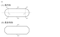
- FIG. 1 is a diagram illustrating the definitions of (A) an oval and (B) a long polygon.
- 1A to 1C are diagrams illustrating a procedure for attaching an earth auger to a heavy machine using a jig according to the present invention.
- 11A and 11B are diagrams illustrating the relationship between the head of a connection pin of a jig according to the present invention and a hole in a gripping portion.
- 11A to 11C are diagrams illustrating the process of drilling a post hole using a jig according to the present invention.
- This jig is a jig for connecting the earth auger 15 and the grapple 17, A cylindrical gripping portion 21 that is gripped by the grapple 17; a connection portion 22 having a plurality of connection pins 23 on a side opposite to the attachment side of the earth auger 15 and suspended from the gripping portion 21 by the connection pins 23; Equipped with.
- FIG. 2 is a three-sided view illustrating the gripping portion 21.
- the gripping portion 21 has a number of holes 21a on its surface that each pass through the connection pins 23 so that the heads of the connection pins 23 are inside, and are large enough that the heads do not fall out.
- FIG. 3 is a two-sided view illustrating the connection portion 22.
- the connection pin 23 is rivet-shaped with a head 23a that is hemispherical on at least the earth auger side.
- the head 23a is hemispherical, but the shape of the head 23a may be spherical.
- This jig is an earth auger jig for directly gripping with a grapple 17.
- This jig requires the following structure. (1) Since the grapple 17 is a device for gripping a cylindrical utility pole, the gripping portion 21 must be cylindrical so that it can be gripped by the grapple 17. (2) At least the lower side (earth auger side) of the head 23a of the connection pin 23 is semi-spherical in shape so that the connection portion 22 is semi-movable with respect to the gripping portion 21. With this structure, when the jig is gripped by the grapple 17, the weight of the earth auger 15 makes the longitudinal direction of the earth auger 15 perpendicular to the ground (perpendicular to the horizontal plane).
- connection portion 22 There are two or more connecting pins 23 so that the earth auger 15 rotates when the grapple 17 rotates.
- a conventional pin fastening structure 24 is adopted for the connection portion 22.
- the earth auger 15 is attached to the connection portion 22 by a pin 26 as shown in FIG.
- the jig preferably has the following structure: (5) All or all but one of the holes 21a of the grip portion 21 are elliptical, oval, or long polygonal in the longitudinal direction of the grip portion 21.
- Fig. 5 is a diagram for explaining the definitions of (A) an oval and (B) a long polygon.
- An ellipse is a shape formed when a circle is cut at one diameter and there are four cut points (a1, a2, a3, a4), and the cut points a1 and a3, and the cut points a2 and a4 are connected by two parallel line segments (ls1, ls2).
- a long polygon is a regular polygon (a regular octagon in FIG. 5) with an even number of vertices of four or more, in which the length of one pair of opposing sides (re1, re2) is longer than the other sides.
- the range in which the earth auger 15 is perpendicular to the horizontal plane under its own weight (the allowable range of inclination of the gripping portion 21 when gripped by the grapple 17) can be expanded.
- All holes 21a may be elliptical, oval, or rectangular, or holes 21a other than one hole 21a may be elliptical, oval, or rectangular.
- FIG. 6 is a diagram explaining the procedure for attaching the earth auger 15 to the heavy equipment 10 using this jig.
- This jig is composed of a gripping part 21 and a connection part 22.
- the gripping part 21 is cylindrical in shape so that it can be gripped by the grapple 17 attached to the heavy equipment 10, and has a hole 21a for connecting to the connection part 22.
- the connection part 22 has a connection pin 23 for connecting to the gripping part 21, and has a pin hole 26 for connecting the earth auger 15 with a pin.
- the grapple 17, heavy equipment 10, and earth auger 15 are commercially available products.
- FIG. 7 is a diagram for explaining the relationship between the head 23 a of the connection pin 23 and the hole 21 a of the grip portion 21 .
- the head 23a of the connection pin 23 is hemispherical so that the connection part 22 can be suspended in a semi-fixed state from the hole 21a of the grip part 21.
- the inner diameter d1 of the grip part 21 is 15 cm to 30 cm.
- the diameter d2 of the head 23a is 5 cm to 15 cm.
- the width of the hole 21a (the width in the direction perpendicular to the longitudinal direction of the hole 21a) at its widest point does not exceed the diameter d2. This is to prevent the head 23a from falling out of the hole 21a.
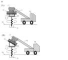
- Figure 8 is a diagram explaining the process of excavating a post hole 51 using this jig.
- Figure 8 (A) explains the excavation process when the long axis direction of the gripping part 21 can be kept parallel to the ground 50 (parallel to the horizontal plane).
- the rotation is transmitted to the connection part 22, causing the earth auger 15 to rotate, and the post hole 51 can be excavated.
- Figure 8 (B) illustrates the excavation process when the longitudinal direction of the gripping portion 21 cannot be kept parallel to the ground 50 (parallel to the horizontal plane).
- the positional relationship between the connection pin 23 of the connection portion 22 of the jig and the hole 21a of the gripping portion 21 changes, so that the earth auger 15 becomes perpendicular to the horizontal plane due to its own weight. Therefore, by rotating the grapple 17, the rotation is transmitted to the connection portion 22, and the earth auger 15, which is perpendicular to the horizontal plane, rotates, and the post hole 51 can be excavated.
Landscapes
- Engineering & Computer Science (AREA)
- Life Sciences & Earth Sciences (AREA)
- Mining & Mineral Resources (AREA)
- Geology (AREA)
- General Life Sciences & Earth Sciences (AREA)
- Environmental & Geological Engineering (AREA)
- Fluid Mechanics (AREA)
- Physics & Mathematics (AREA)
- Geochemistry & Mineralogy (AREA)
- Paleontology (AREA)
- Civil Engineering (AREA)
- General Engineering & Computer Science (AREA)
- Structural Engineering (AREA)
- Mechanical Engineering (AREA)
- Earth Drilling (AREA)
Priority Applications (2)
| Application Number | Priority Date | Filing Date | Title |
|---|---|---|---|
| JP2025513510A JPWO2024214140A1 (https=) | 2023-04-10 | 2023-04-10 | |
| PCT/JP2023/014543 WO2024214140A1 (ja) | 2023-04-10 | 2023-04-10 | 把持式アースオーガ |
Applications Claiming Priority (1)
| Application Number | Priority Date | Filing Date | Title |
|---|---|---|---|
| PCT/JP2023/014543 WO2024214140A1 (ja) | 2023-04-10 | 2023-04-10 | 把持式アースオーガ |
Publications (1)
| Publication Number | Publication Date |
|---|---|
| WO2024214140A1 true WO2024214140A1 (ja) | 2024-10-17 |
Family
ID=93058917
Family Applications (1)
| Application Number | Title | Priority Date | Filing Date |
|---|---|---|---|
| PCT/JP2023/014543 Ceased WO2024214140A1 (ja) | 2023-04-10 | 2023-04-10 | 把持式アースオーガ |
Country Status (2)
| Country | Link |
|---|---|
| JP (1) | JPWO2024214140A1 (https=) |
| WO (1) | WO2024214140A1 (https=) |
Citations (6)
| Publication number | Priority date | Publication date | Assignee | Title |
|---|---|---|---|---|
| JPH0278685U (https=) * | 1988-11-30 | 1990-06-18 | ||
| JPH0416781U (https=) * | 1990-05-31 | 1992-02-12 | ||
| JPH0522489U (ja) * | 1991-08-30 | 1993-03-23 | 株式会社アイチコーポレーシヨン | 把持式建柱作業車 |
| JP2018012960A (ja) * | 2016-07-20 | 2018-01-25 | 哲山 松本 | 排土処理用アタッチメント |
| JP2018108878A (ja) * | 2016-12-29 | 2018-07-12 | 哲山 松本 | 吊り具アダプタ |
| CN115126326A (zh) * | 2022-07-04 | 2022-09-30 | 山东肯石重工机械有限公司 | 电网线杆安装专用设备 |
-
2023
- 2023-04-10 JP JP2025513510A patent/JPWO2024214140A1/ja active Pending
- 2023-04-10 WO PCT/JP2023/014543 patent/WO2024214140A1/ja not_active Ceased
Patent Citations (6)
| Publication number | Priority date | Publication date | Assignee | Title |
|---|---|---|---|---|
| JPH0278685U (https=) * | 1988-11-30 | 1990-06-18 | ||
| JPH0416781U (https=) * | 1990-05-31 | 1992-02-12 | ||
| JPH0522489U (ja) * | 1991-08-30 | 1993-03-23 | 株式会社アイチコーポレーシヨン | 把持式建柱作業車 |
| JP2018012960A (ja) * | 2016-07-20 | 2018-01-25 | 哲山 松本 | 排土処理用アタッチメント |
| JP2018108878A (ja) * | 2016-12-29 | 2018-07-12 | 哲山 松本 | 吊り具アダプタ |
| CN115126326A (zh) * | 2022-07-04 | 2022-09-30 | 山东肯石重工机械有限公司 | 电网线杆安装专用设备 |
Also Published As
| Publication number | Publication date |
|---|---|
| JPWO2024214140A1 (https=) | 2024-10-17 |
Similar Documents
| Publication | Publication Date | Title |
|---|---|---|
| JP5872061B2 (ja) | 風力発電装置の組立方法、及びそれに用いられるカウンターウェイト | |
| KR20150023385A (ko) | 굴착장치 및 굴착장치에서 굴착 파이프 구성요소의 핸들링 하는 장치 및 방법 | |
| CN101317006A (zh) | 风轮机塔架、用于装配风轮机塔架的连接装置及其方法 | |
| JP6177287B2 (ja) | 鋼管連結構造及び鋼管連結方法 | |
| WO2024214140A1 (ja) | 把持式アースオーガ | |
| JP6629948B1 (ja) | 仮支持柱、電柱建替支援装置及び電柱建替方法 | |
| JP2019052453A (ja) | 立て坑掘削装置および立て坑掘削方法 | |
| CN114977010B (zh) | 一种锁线轮式防滑脱放线滑车 | |
| CN218150892U (zh) | 一种适用于地质钻孔的振动传感器固定装置 | |
| CN103485342B (zh) | 多角度抱桩装置及液压打桩锤多作用试车台 | |
| CN110924877B (zh) | 高强肋骨钻杆 | |
| KR101385818B1 (ko) | 파일의 수직 시공을 위한 모터 고정장치 | |
| JP3535894B2 (ja) | パワーショベルのバケット取付具 | |
| CN104439380B (zh) | 一种钻摩托车离合器中心套油孔的机床 | |
| CN113737779A (zh) | 钢筋连接调整螺母、组件及预制桩和基础承台连接结构 | |
| JP3242839U (ja) | 掘削用バケット | |
| JP4863343B2 (ja) | 削孔装置及び圧入機 | |
| CN202031483U (zh) | 一种钻孔机械及其筒式钻具 | |
| CN113530456B (zh) | 一种多边形打孔工具 | |
| CN215408527U (zh) | 钻机用卸杆装置 | |
| JP2006283516A (ja) | 掘削工具及び掘削工法 | |
| CN218563597U (zh) | 定位器及方桩钻头 | |
| CN210968645U (zh) | 一种组合套筒 | |
| CN216583755U (zh) | 一种旋挖钻方头吊具 | |
| KR100302078B1 (ko) | 암반굴착용비트 |
Legal Events
| Date | Code | Title | Description |
|---|---|---|---|
| 121 | Ep: the epo has been informed by wipo that ep was designated in this application |
Ref document number: 23932922 Country of ref document: EP Kind code of ref document: A1 |
|
| ENP | Entry into the national phase |
Ref document number: 2025513510 Country of ref document: JP Kind code of ref document: A |
|
| WWE | Wipo information: entry into national phase |
Ref document number: 2025513510 Country of ref document: JP |
|
| NENP | Non-entry into the national phase |
Ref country code: DE |
|
| 122 | Ep: pct application non-entry in european phase |
Ref document number: 23932922 Country of ref document: EP Kind code of ref document: A1 |