WO2024209942A1 - 光干渉計測方法 - Google Patents
光干渉計測方法 Download PDFInfo
- Publication number
- WO2024209942A1 WO2024209942A1 PCT/JP2024/010953 JP2024010953W WO2024209942A1 WO 2024209942 A1 WO2024209942 A1 WO 2024209942A1 JP 2024010953 W JP2024010953 W JP 2024010953W WO 2024209942 A1 WO2024209942 A1 WO 2024209942A1
- Authority
- WO
- WIPO (PCT)
- Prior art keywords
- light
- measurement
- interference
- optical
- range
- Prior art date
- Legal status (The legal status is an assumption and is not a legal conclusion. Google has not performed a legal analysis and makes no representation as to the accuracy of the status listed.)
- Ceased
Links
Images




Classifications
-
- G—PHYSICS
- G01—MEASURING; TESTING
- G01B—MEASURING LENGTH, THICKNESS OR SIMILAR LINEAR DIMENSIONS; MEASURING ANGLES; MEASURING AREAS; MEASURING IRREGULARITIES OF SURFACES OR CONTOURS
- G01B9/00—Measuring instruments characterised by the use of optical techniques
- G01B9/02—Interferometers
- G01B9/0209—Low-coherence interferometers
- G01B9/02091—Tomographic interferometers, e.g. based on optical coherence
-
- G—PHYSICS
- G01—MEASURING; TESTING
- G01B—MEASURING LENGTH, THICKNESS OR SIMILAR LINEAR DIMENSIONS; MEASURING ANGLES; MEASURING AREAS; MEASURING IRREGULARITIES OF SURFACES OR CONTOURS
- G01B11/00—Measuring arrangements characterised by the use of optical techniques
- G01B11/02—Measuring arrangements characterised by the use of optical techniques for measuring length, width or thickness
- G01B11/06—Measuring arrangements characterised by the use of optical techniques for measuring length, width or thickness for measuring thickness ; e.g. of sheet material
-
- G—PHYSICS
- G01—MEASURING; TESTING
- G01B—MEASURING LENGTH, THICKNESS OR SIMILAR LINEAR DIMENSIONS; MEASURING ANGLES; MEASURING AREAS; MEASURING IRREGULARITIES OF SURFACES OR CONTOURS
- G01B9/00—Measuring instruments characterised by the use of optical techniques
- G01B9/02—Interferometers
- G01B9/02001—Interferometers characterised by controlling or generating intrinsic radiation properties
- G01B9/02002—Interferometers characterised by controlling or generating intrinsic radiation properties using two or more frequencies
-
- G—PHYSICS
- G01—MEASURING; TESTING
- G01B—MEASURING LENGTH, THICKNESS OR SIMILAR LINEAR DIMENSIONS; MEASURING ANGLES; MEASURING AREAS; MEASURING IRREGULARITIES OF SURFACES OR CONTOURS
- G01B9/00—Measuring instruments characterised by the use of optical techniques
- G01B9/02—Interferometers
- G01B9/02001—Interferometers characterised by controlling or generating intrinsic radiation properties
- G01B9/02002—Interferometers characterised by controlling or generating intrinsic radiation properties using two or more frequencies
- G01B9/02004—Interferometers characterised by controlling or generating intrinsic radiation properties using two or more frequencies using frequency scans
-
- G—PHYSICS
- G01—MEASURING; TESTING
- G01B—MEASURING LENGTH, THICKNESS OR SIMILAR LINEAR DIMENSIONS; MEASURING ANGLES; MEASURING AREAS; MEASURING IRREGULARITIES OF SURFACES OR CONTOURS
- G01B9/00—Measuring instruments characterised by the use of optical techniques
- G01B9/02—Interferometers
- G01B9/02001—Interferometers characterised by controlling or generating intrinsic radiation properties
- G01B9/02007—Two or more frequencies or sources used for interferometric measurement
- G01B9/02008—Two or more frequencies or sources used for interferometric measurement by using a frequency comb
-
- G—PHYSICS
- G01—MEASURING; TESTING
- G01B—MEASURING LENGTH, THICKNESS OR SIMILAR LINEAR DIMENSIONS; MEASURING ANGLES; MEASURING AREAS; MEASURING IRREGULARITIES OF SURFACES OR CONTOURS
- G01B9/00—Measuring instruments characterised by the use of optical techniques
- G01B9/02—Interferometers
- G01B9/02055—Reduction or prevention of errors; Testing; Calibration
- G01B9/0207—Error reduction by correction of the measurement signal based on independently determined error sources, e.g. using a reference interferometer
-
- G—PHYSICS
- G01—MEASURING; TESTING
- G01B—MEASURING LENGTH, THICKNESS OR SIMILAR LINEAR DIMENSIONS; MEASURING ANGLES; MEASURING AREAS; MEASURING IRREGULARITIES OF SURFACES OR CONTOURS
- G01B9/00—Measuring instruments characterised by the use of optical techniques
- G01B9/02—Interferometers
- G01B9/0209—Low-coherence interferometers
-
- G—PHYSICS
- G01—MEASURING; TESTING
- G01N—INVESTIGATING OR ANALYSING MATERIALS BY DETERMINING THEIR CHEMICAL OR PHYSICAL PROPERTIES
- G01N21/00—Investigating or analysing materials by the use of optical means, i.e. using sub-millimetre waves, infrared, visible or ultraviolet light
- G01N21/17—Systems in which incident light is modified in accordance with the properties of the material investigated
-
- G—PHYSICS
- G01—MEASURING; TESTING
- G01B—MEASURING LENGTH, THICKNESS OR SIMILAR LINEAR DIMENSIONS; MEASURING ANGLES; MEASURING AREAS; MEASURING IRREGULARITIES OF SURFACES OR CONTOURS
- G01B2290/00—Aspects of interferometers not specifically covered by any group under G01B9/02
- G01B2290/25—Fabry-Perot in interferometer, e.g. etalon, cavity
Definitions
- This disclosure relates to an optical interference measurement method that measures an object using interference light between reflected light and a reference light.
- OCT optical coherence tomography
- OCT is a method for taking cross-sectional images of structures such as paint films or living organisms, utilizing the phenomenon of optical interference.
- OCT has already been put to practical use in the field of ophthalmology, where it has been used as a cross-sectional measurement method with a high resolution of several tens of micrometers to take cross-sectional images of minute areas inside the eye, such as the retina.
- TD-OCT time domain OCT
- FD-OCT frequency domain OCT
- SS-OCT wavelength scanning light source type
- Figure 5 shows a conventional SD-OCT device described in Patent Document 1.
- a broadband light source 2 is split into reference light and measurement light by a beam splitter 5, and the reference light passes through a lens 9 and a mirror 10 to a spectrometer 4, while the measurement light passes through a lens 6 and a galvanometer mirror 7 to reach a measurement object 8 and is reflected from the measurement object 8 before similarly entering the spectrometer 4.
- the measurement light and reference light interfere in the spectral region to generate an interference signal.
- the interference signal reaches the CCD 12 via the diffraction grating 11.
- the CCD 12 measures the interference fringes as an interference signal.
- An optical interference measurement method includes: light emitted from a low-coherence light source and adjusted to have equal frequency intervals is split by a light splitting means into a measurement light and a reference light; While the measurement light is scanned by a scanning mechanism, a surface shape profile is obtained from an interference signal of interference light that is generated by combining the reference light and reflected light from the measurement object after the measurement light is incident, and when the measurement light is incident on the measurement target, a range obtained by adding a measurement range determined by an interference light detection means from a zero point where a signal optical path length of the signal light, which is the measurement light, and a reference optical path length of the reference light coincide with each other overlaps with a range obtained by subtracting the measurement range from a distance from the zero point that is half a value obtained by multiplying the reciprocal of the mode spacing of an optical comb generating filter by the speed of light, When the scanning mechanism scans, a change in distance between the scanning mechanism and the measurement object due to the scanning mechanism exceeds twice the
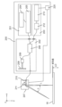
- FIG. 1 is a diagram showing an overall configuration of an SD-OCT device according to an embodiment.
- FIG. 1 shows a Fabry-Perot filter according to an embodiment.
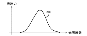
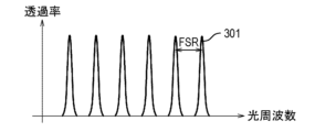
- Transmittance of an optical frequency comb source in the frequency domain A diagram showing the optical output of an optical frequency comb source in the frequency domain.
- FIG. 1 is a diagram of a coherence region of an SD-OCT device according to a first embodiment.
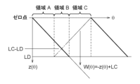
- Diagram of the interference signal z( ⁇ ) obtained by measuring W( ⁇ ) 1 is a diagram showing conversion from an interference signal to a surface shape in the first embodiment.
- FIG. 1 shows a conventional SD-OCT device described in Patent Document 1.
- the measurement range in the depth direction i.e., half the maximum value of the optical path length difference between the reference light and the measurement light at which spectral interference fringes can be obtained correctly, is limited by the optical frequency resolution of the spectrometer. Therefore, in the conventional configuration described above, the change in distance to the measurement object 8 caused by scanning the galvanometer mirror 7, which is the scanning mechanism, cannot be made larger than the measurement range in the depth direction, which creates an issue of limitations on the measurable size of the measurement object 8 in the scanning direction.
- the present disclosure aims to solve the problems of the past and provide an optical interference measurement method that can measure even when the change in distance to the measurement object due to scanning is greater than the measurement range in the depth direction.
- FIG. 1 is a diagram showing the overall configuration of an SD-OCT (spectrometer-type optical coherence tomography) device 200 and a scanning mechanism 211 as an example of an optical interference measurement device for implementing an optical interference measurement method according to an embodiment.
- SD-OCT spectrometer-type optical coherence tomography
- the SD-OCT device 200 includes at least an optical frequency comb source 201, a coupler 206 as an example of a light splitting means, and a detector array 213 as an example of an interference light detection means.
- the optical frequency comb source 201 includes a low coherence light source 204 and an optical comb generating filter 205.
- the SD-OCT device 200 further includes an optical fiber interferometer 202, which is a Michelson interferometer, a spectrometer 203 having an interference light detection means, and a calculation unit 220.
- the optical frequency comb light source 201 is a light source with an equally spaced optical frequency distribution.
- the optical frequency comb light source 201 is composed of a low coherence light source 204 and an optical comb generating filter 205 that adjusts the low coherence light emitted from the low coherence light source 204 to an equally spaced optical frequency distribution.
- the low coherence light source 204 includes an SLD (super luminescent diode), an ultrashort pulse laser, a supercontinuum light source, or the like.
- the light emitted from the low coherence light source 204 is shaped by the optical comb generating filter 205 into an equally spaced optical frequency distribution, i.e., into a comb shape with equal frequency intervals. Details of the shaped optical frequencies will be described later.
- the light generated by the optical frequency comb light source 201 enters the optical fiber interferometer 202.
- the optical fiber interferometer 202 has a coupler 206 connected to two light receiving ports and two light transmitting ports.
- the optical output port of the optical frequency comb light source 201 is connected to the first of the two optical receiving ports of the optical fiber interferometer 202, and is split into measurement light and reference light by the coupler 206.
- the optical output port of the coupler 206 is connected to a measurement head 207 outside the optical fiber interferometer 202 as signal light, and is also connected to a collimating lens 209 that enters a reference surface 208 as reference light.
- the reference light is reflected at the reference surface 208, passes through the collimating lens 209, enters the coupler 206, and enters the spectrometer 203 through the second of the two light receiving ports of the optical fiber interferometer 202.
- the measurement light is irradiated onto the measurement object W via the illumination lens 210 and scanning mechanism 211 in the measurement head 207, is reflected or scattered by the measurement object W, enters the coupler 206 from the measurement head 207, and enters the spectrometer 203 from the second light receiving port of the optical fiber interferometer 202.
- the point where the signal path length of the signal light, which is the measurement light, and the reference path length of the reference light coincide is shown in FIG. 1, i.e., the zero point.
- the position of the zero point in the embodiment can be freely changed by changing, for example, the distance between the collimating lens 209 and the reference surface 208, or the distance in the fiber between the coupler 206 and the collimating lens 209, and can also be disposed, for example, between the measurement head 207 and the coupler 206.
- the calculation unit 220 performs measurement processing such as calculations based on information from the detector array 213 and the scanning mechanism 211 (described later) to obtain a surface shape profile of the measurement object W.
- the spectrometer 203 has a diffraction grating 212 connected to the optical fiber interferometer 202, and a detector array 213 connected to the diffraction grating 212.
- the two beams of measurement light and reference light are simultaneously split by the diffraction grating 212 of the spectrometer 203, and the reflected light and the reference light interfere in the optical frequency domain to become interference light in which they are combined, and as a result, the interference signal of the interference light is measured by the detector array 213, which is an example of an interference light detection means.
- the differential one-dimensional refractive index distribution in the signal optical path of the measurement light of the measurement object W that is, the reflectance distribution.
- the positive or negative sign of the optical path length difference is defined as being determined by the positive or negative sign of the calculation result obtained by subtracting the reference optical path length from the signal optical path length.
- the maximum measurable range is a range of ⁇ LD centered on the zero point.
- the optical frequency that can be resolved by one pixel of the detector array 213 is the frequency resolution dv
- the maximum time difference between the measurement light and the reference light observed by the spectroscope 203 is 1/2 dv according to the Nyquist sampling theorem.
- LD c/4 dv (1), where c is the speed of light.
- the frequency resolution dv is limited by the finite number of pixels of the detector array 213, and therefore there is a limit.
- the scanning mechanism 211 is an element capable of changing the reflection direction of the measurement light, such as a galvanometer scanner, a polygon scanner, or a resonance scanner, and is capable of scanning the measurement light in the ⁇ direction. By continuously scanning the measurement light in the ⁇ direction using the scanning mechanism 211, the surface shape of the measurement object W in the X direction can be measured.
- the optical frequency comb source 201 which is an optical frequency comb generator
- the optical comb generating filter 205 is a Fabry-Perot filter with a finesse range of 2 to 20, in which an optical resonator is formed by sandwiching an air gap 214 with a cavity length LC between two half mirror pairs 215 with reflectance R, as shown in Figure 2A.
- FIG. 2B shows the pre-filter output of the optical frequency comb light source 201
- FIG. 2C shows the filter transmittance of the optical frequency comb light source 201
- FIG. 2D shows the output of the optical frequency comb light source 201 in the frequency domain.
- the vertical axis represents the optical output, transmittance, and optical output, respectively
- the horizontal axis represents the optical frequency.
- the spectrum 300 (see FIG. 2B) of the original low coherence light source 204 is multiplied by the transmittance spectrum 301 (see FIG. 2C) of the optical comb generating filter 205, and adjusted to a comb-like output spectrum 302 (see FIG. 2D) in which modes with equal mode spacing FSR stand.
- the optical frequency comb light source 201 does not have to be a combination of a low coherence light source 204 and an optical comb generating filter 205; it can also be a mode-locked laser with a stabilized repetition frequency, or a single mode laser modulated by an electro-optical element to create a comb-like mode, or a high-finesse etalon.
- a coupler 206 is used to combine the light, but the optical fiber interferometer 202 may be constructed in free space using a beam splitter, or an element such as an optical circulator may be used instead.
- ⁇ About the coherence region of the SD-OCT device> 3 shows the coherence region of the SD-OCT device 200 in this embodiment.
- the range of optical path length difference in which an interference signal can be obtained is called the coherence region.
- the intensity of the interference signal is constant and the width is a rectangle of ⁇ LD.
- an interference signal is detected in the range of optical path length difference 0 ⁇ LD. This is called the zero-order coherence region.
- an interference signal can also be obtained in the region of depth LC ⁇ LD.
- the time domain it can be thought of as light with a time delay of 2LC/c ⁇ (n+1) and light with a time delay of 2LC/c ⁇ n being interfered with by the optical comb generating filter 205, with the time difference between each being eliminated by the round-trip time difference of 2LC/c between the zero point and the measurement object W. This is called the first-order coherence region.
- an interference signal can be obtained in the region of depth 2LC ⁇ LD.
- the range of cavity length LC must be LC ⁇ 2LD, as shown in Figure 3. Doing so makes it possible to provide an overlapping region between the zeroth-order coherence region and the first-order coherence region, eliminating the dead zone between the zeroth-order coherence region and the first-order coherence region.
- the cavity length LC is between LD ⁇ LC ⁇ 2LD.
- the surface of the object W to be measured that can be measured in the zero-order coherence region must be located within the measurement range ⁇ LD determined by the frequency resolution dv of the spectrometer 203 from the zero point (the range from the zero point plus the measurement range ⁇ LD determined by the interference light detection means).
- the incident angle (i.e., the scanning angle) of the measurement light emitted from the scanning mechanism 211 to the measurement target W is ⁇
- the distance between the measurement target W and the scanning mechanism 211 is L/cos ⁇ .
- the change in the distance, i.e., the difference from the shortest distance L is L(1-1/cos ⁇ ).
- the change in the distance (L/cos ⁇ ) between the scanning mechanism 211 and the measurement target W caused by the scanning (L/cos ⁇ ) is set to be twice the measurement range LD determined by the interference light detection means, i.e., 2LD.
- the zero point is set to coincide with L
- the displacement W( ⁇ ) represents the surface shape profile of the measurement target W with respect to the distance L.
- Figure 4A shows the relationship of displacement W( ⁇ ) to scanning angle ⁇ when scanning mechanism 211 is scanned. As the scanning angle ⁇ increases, the distance between the measurement object W and scanning mechanism 211 increases, and displacement W( ⁇ ) increases. In reality, displacement W( ⁇ ) to scanning angle ⁇ is nonlinear as shown in the formula, but since it increases monotonically, it is treated as linear for simplicity of explanation.
- Figure 4B shows the interference signal z( ⁇ ) obtained by observing the displacement W( ⁇ ) using the SD-OCT device 200.
- Area A shown in Figure 4B is the area where the depth of the interference signal is located from the zero point to the LC-LD.
- the interference signal is only the zero-order coherence area, and one interference signal is obtained.
- the observed interference signal z( ⁇ ) is taken as the displacement W( ⁇ ) as it is.
- Area B shown in Figure 4B is the area where the depth z of the interference signal is located from LC-LD to LD.
- the interference signal is included in both the zero-order coherence region and the first-order coherence region, so two interference signals are obtained as the observed interference signal z( ⁇ ).
- these two interference signals When these two interference signals are obtained, they must be converted into a displacement W( ⁇ ) relative to the shortest distance L to the surface of the measurement target W.
- the one that monotonically decreases in the ⁇ direction i.e., the one of z( ⁇ ) whose slope with respect to the scanning angle ⁇ is negative, is determined to be the zero-order interference signal and is taken as the displacement W( ⁇ ).
- Area C shown in Figure 4B is the area where the depth z of the interference signal is located from LD to LC.
- the interference signal is located only in the first-order coherence area, and one interference signal is obtained.
- interference signals can only be obtained from regions A and B, but as shown in Figure 3 above, because the coherence regions are continuous in the depth z direction, interference signals can also be obtained from region C, where the depth z is outside the zero-order coherence region.
- the actual depth is an image that is folded back symmetrically around the zero point.
- the fact that it is a folded image can be determined by the fact that the displacement W( ⁇ ) should be monotonically decreasing but is monotonically increasing with respect to the scanning angle ⁇ .
- the depth of the interference signal is used as the surface shape profile as it is, in region B where two interference signals are obtained, the interference signal with a negative slope with respect to ⁇ is used, and in region C where a folded image is obtained, the interference signal is inverted and corrected to eliminate zero-point symmetry, thereby obtaining a surface shape profile from the obtained interference signal.
- the calculation unit 220 selects one of the two interference signals using the sign of the change in distance of the interference light with respect to the scanning angle ⁇ of the scanning mechanism 211, while in regions A and C where one interference signal is observed, the calculation unit 220 determines whether to invert and correct the interference signal using the sign of the change in distance of the interference light with respect to the scanning angle ⁇ of the scanning mechanism 211.
- the calculation unit 220 performs inverted correction of the interference signal, as shown in formula (5), half the value obtained by multiplying the reciprocal of the mode spacing FSR of the optical comb generating filter by the speed of light c, i.e., c/2FSR, i.e., LC, is added.
- a surface shape profile can be obtained from the obtained interference signal, and the surface position can be measured. An overview of this is shown in Figure 4C.
- This method is not preferable when the scanning mechanism 211 discretely changes the measurement position, because it becomes impossible to distinguish the inclination relative to the scanning angle ⁇ .
- the following optical interference measurement method is performed. That is, as the optical interference measurement method, low coherence light is emitted from the low coherence light source 204, The light emitted from the low-coherence light source 204 is adjusted by the optical comb generating filter 205 to have an equally spaced optical frequency distribution.
- the light adjusted to have equal frequency intervals by the optical comb generating filter 205 is split into measurement light and reference light by a coupler 206 as an example of a light splitting means, While the measurement light is scanned by the scanning mechanism 211 at a scanning angle ⁇ at which it is incident on the measurement object W, the interference light generated by combining the reflected light from the measurement object W and the reference light after the measurement light is incident is detected by the interference light detection means, and the surface shape profile of the measurement object W can be obtained from the interference signal of the detected interference light.
- the light adjusted to equal frequency intervals by the optical comb generating filter is split into measurement light and reference light by the optical splitting means, and when the measurement light is incident on the measurement object, the range obtained by adding the measurement range determined by the interference light detection means to the zero point where the signal optical path length of the signal light, which is the measurement light, and the reference optical path length of the reference light coincide with each other overlaps with the range obtained by subtracting the measurement range from the distance from the zero point that is half the value obtained by multiplying the inverse of the mode interval of the optical comb generating filter by the speed of light, and when scanning by the scanning mechanism, the amount of change in the distance between the scanning mechanism and the measurement object due to the scanning of the scanning mechanism exceeds twice the measurement range determined by the interference light detection means, and the interference light obtained by combining the reflected light from the measurement object and the reference light of the measurement light is detected by the interference light detection means.
- the optical interference measurement method has the characteristic that it can continuously measure the surface shape of the object even if the change in distance to the object due to scanning is greater than the measurement range, making it possible to measure the surface shape over a long distance and in a wide range, and can also be used for precision measurements in the industrial field.
Landscapes
- Physics & Mathematics (AREA)
- General Physics & Mathematics (AREA)
- Health & Medical Sciences (AREA)
- General Health & Medical Sciences (AREA)
- Radiology & Medical Imaging (AREA)
- Nuclear Medicine, Radiotherapy & Molecular Imaging (AREA)
- Biochemistry (AREA)
- Analytical Chemistry (AREA)
- Immunology (AREA)
- Pathology (AREA)
- Chemical & Material Sciences (AREA)
- Life Sciences & Earth Sciences (AREA)
- Instruments For Measurement Of Length By Optical Means (AREA)
- Length Measuring Devices By Optical Means (AREA)
Priority Applications (2)
| Application Number | Priority Date | Filing Date | Title |
|---|---|---|---|
| JP2025512484A JPWO2024209942A1 (https=) | 2023-04-06 | 2024-03-21 | |
| US19/331,356 US20260016282A1 (en) | 2023-04-06 | 2025-09-17 | Optical interference measuring method |
Applications Claiming Priority (2)
| Application Number | Priority Date | Filing Date | Title |
|---|---|---|---|
| JP2023062191 | 2023-04-06 | ||
| JP2023-062191 | 2023-04-06 |
Related Child Applications (1)
| Application Number | Title | Priority Date | Filing Date |
|---|---|---|---|
| US19/331,356 Continuation US20260016282A1 (en) | 2023-04-06 | 2025-09-17 | Optical interference measuring method |
Publications (1)
| Publication Number | Publication Date |
|---|---|
| WO2024209942A1 true WO2024209942A1 (ja) | 2024-10-10 |
Family
ID=92973129
Family Applications (1)
| Application Number | Title | Priority Date | Filing Date |
|---|---|---|---|
| PCT/JP2024/010953 Ceased WO2024209942A1 (ja) | 2023-04-06 | 2024-03-21 | 光干渉計測方法 |
Country Status (3)
| Country | Link |
|---|---|
| US (1) | US20260016282A1 (https=) |
| JP (1) | JPWO2024209942A1 (https=) |
| WO (1) | WO2024209942A1 (https=) |
Citations (3)
| Publication number | Priority date | Publication date | Assignee | Title |
|---|---|---|---|---|
| US20120050746A1 (en) * | 2010-08-29 | 2012-03-01 | Shivani Sharma | Apparatus and method for increasing depth range and signal to noise ratio in fourier domain low coherence interferometry |
| JP2021021744A (ja) * | 2014-08-27 | 2021-02-18 | 国立大学法人電気通信大学 | 距離測定装置 |
| WO2023210116A1 (ja) * | 2022-04-27 | 2023-11-02 | パナソニックIpマネジメント株式会社 | 光干渉計測装置 |
-
2024
- 2024-03-21 JP JP2025512484A patent/JPWO2024209942A1/ja active Pending
- 2024-03-21 WO PCT/JP2024/010953 patent/WO2024209942A1/ja not_active Ceased
-
2025
- 2025-09-17 US US19/331,356 patent/US20260016282A1/en active Pending
Patent Citations (3)
| Publication number | Priority date | Publication date | Assignee | Title |
|---|---|---|---|---|
| US20120050746A1 (en) * | 2010-08-29 | 2012-03-01 | Shivani Sharma | Apparatus and method for increasing depth range and signal to noise ratio in fourier domain low coherence interferometry |
| JP2021021744A (ja) * | 2014-08-27 | 2021-02-18 | 国立大学法人電気通信大学 | 距離測定装置 |
| WO2023210116A1 (ja) * | 2022-04-27 | 2023-11-02 | パナソニックIpマネジメント株式会社 | 光干渉計測装置 |
Also Published As
| Publication number | Publication date |
|---|---|
| JPWO2024209942A1 (https=) | 2024-10-10 |
| US20260016282A1 (en) | 2026-01-15 |
Similar Documents
| Publication | Publication Date | Title |
|---|---|---|
| US7969578B2 (en) | Method and apparatus for performing optical imaging using frequency-domain interferometry | |
| Izatt et al. | Theory of optical coherence tomography | |
| CN102192896B (zh) | 光干涉测量方法及光干涉测量装置 | |
| US9696134B2 (en) | System for performing dual path, two-dimensional optical coherence tomography (OCT) | |
| US7751056B2 (en) | Optical coherence tomographic imaging apparatus | |
| JP6160827B2 (ja) | 光コヒーレンストモグラフィー装置 | |
| US20120013849A1 (en) | Apparatus and method of monitoring and measurement using spectral low coherence interferometry | |
| US20150109622A1 (en) | Optical coherence tomography apparatus and optical coherence tomography method | |
| GB2407155A (en) | Spectral interferometry method and apparatus | |
| JP2006052954A (ja) | 多重化スペクトル干渉光コヒーレンストモグラフィー | |
| US20120013909A1 (en) | Apparatus and method of monitoring and measurement using spectral low coherence interferometry | |
| JP4461258B2 (ja) | 光断層画像化法における補正方法 | |
| JP4852651B2 (ja) | 多重化スペクトル干渉光コヒーレンストモグラフィー | |
| EP1870028A1 (en) | Apparatus and method for frequency domain optical coherence tomography | |
| WO2024209942A1 (ja) | 光干渉計測方法 | |
| WO2023210116A1 (ja) | 光干渉計測装置 | |
| JP5149923B2 (ja) | 多重化スペクトル干渉光コヒーレンストモグラフィー | |
| Batista et al. | Swept-source Phase-Stabilized Optical Coherence Tomography Setup for Elastography. | |
| JP6790879B2 (ja) | Oct装置 | |
| Al-Mohamedi et al. | A systematic comparison and evaluation of three different Swept-Source interferometers for eye lengths biometry | |
| Podoleanu | Route to OCT from OFS at university of Kent |
Legal Events
| Date | Code | Title | Description |
|---|---|---|---|
| 121 | Ep: the epo has been informed by wipo that ep was designated in this application |
Ref document number: 24784733 Country of ref document: EP Kind code of ref document: A1 |
|
| ENP | Entry into the national phase |
Ref document number: 2025512484 Country of ref document: JP Kind code of ref document: A |
|
| WWE | Wipo information: entry into national phase |
Ref document number: 2025512484 Country of ref document: JP |
|
| NENP | Non-entry into the national phase |
Ref country code: DE |
|
| 122 | Ep: pct application non-entry in european phase |
Ref document number: 24784733 Country of ref document: EP Kind code of ref document: A1 |