WO2024209735A1 - 搬送装置、プレス装置システムおよび搬送装置の制御方法 - Google Patents
搬送装置、プレス装置システムおよび搬送装置の制御方法 Download PDFInfo
- Publication number
- WO2024209735A1 WO2024209735A1 PCT/JP2023/041873 JP2023041873W WO2024209735A1 WO 2024209735 A1 WO2024209735 A1 WO 2024209735A1 JP 2023041873 W JP2023041873 W JP 2023041873W WO 2024209735 A1 WO2024209735 A1 WO 2024209735A1
- Authority
- WO
- WIPO (PCT)
- Prior art keywords
- strip
- press
- length
- speed
- metal strip
- Prior art date
- Legal status (The legal status is an assumption and is not a legal conclusion. Google has not performed a legal analysis and makes no representation as to the accuracy of the status listed.)
- Ceased
Links
Images








Classifications
-
- B—PERFORMING OPERATIONS; TRANSPORTING
- B21—MECHANICAL METAL-WORKING WITHOUT ESSENTIALLY REMOVING MATERIAL; PUNCHING METAL
- B21D—WORKING OR PROCESSING OF SHEET METAL OR METAL TUBES, RODS OR PROFILES WITHOUT ESSENTIALLY REMOVING MATERIAL; PUNCHING METAL
- B21D43/00—Feeding, positioning or storing devices combined with, or arranged in, or specially adapted for use in connection with, apparatus for working or processing sheet metal, metal tubes or metal profiles; Associations therewith of cutting devices
- B21D43/02—Advancing work in relation to the stroke of the die or tool
- B21D43/025—Fault detection, e.g. misfeed detection
-
- B—PERFORMING OPERATIONS; TRANSPORTING
- B21—MECHANICAL METAL-WORKING WITHOUT ESSENTIALLY REMOVING MATERIAL; PUNCHING METAL
- B21D—WORKING OR PROCESSING OF SHEET METAL OR METAL TUBES, RODS OR PROFILES WITHOUT ESSENTIALLY REMOVING MATERIAL; PUNCHING METAL
- B21D43/00—Feeding, positioning or storing devices combined with, or arranged in, or specially adapted for use in connection with, apparatus for working or processing sheet metal, metal tubes or metal profiles; Associations therewith of cutting devices
- B21D43/02—Advancing work in relation to the stroke of the die or tool
- B21D43/021—Control or correction devices in association with moving strips
-
- B—PERFORMING OPERATIONS; TRANSPORTING
- B30—PRESSES
- B30B—PRESSES IN GENERAL
- B30B15/00—Details of, or accessories for, presses; Auxiliary measures in connection with pressing
- B30B15/30—Feeding material to presses
Definitions
- This disclosure relates to a conveying device, a press device system, and a method for controlling the conveying device.
- Some conveying devices are installed in press machines and intermittently send a set length of strip to the press machine each time the press process is completed.
- Some conveying devices devices that can send strip to the press machine with high precision have been developed.
- Patent Document 1 discloses a transport device that includes a storage device in which an error in the feed length for feeding a strip to a press device is stored in advance as correction information, and a controller that controls a motor, which is a drive source for feeding the strip, based on the correction information.
- the conveying device described in Patent Document 1 requires that correction information for the strip be determined in advance and stored in a storage device. As a result, this conveying device has difficulty in feeding the strip with high precision when the strip does not have correction information stored in the storage device in advance. For example, the conveying device described in Patent Document 1 has difficulty in feeding the strip with high precision when the thickness or surface friction of the strip changes.
- the present disclosure has been made to solve the above problems, and aims to provide a conveying device, a press machine system, and a control method for the conveying device that can feed a strip with high accuracy even without correction information for the strip.
- the conveying device includes a feed device, a pressing device, a measuring unit, and a control unit.
- the feed device intermittently feeds the strip to the press device by a set length each time press processing is completed.
- the pressing device presses a tensioner against the strip to generate tension in the strip and slows down the speed of the strip by the feed device.
- the measuring unit measures the length of the strip actually fed by the feed device between the previous specific press state and the current specific press state.
- the control unit finds the deviation between the actual feed length of the strip measured by the measuring unit and the set length, and controls the force with which the pressing device presses the tensioner against the strip based on the deviation.
- control unit determines the deviation between the actual feed length of the strip measured by the measurement unit and the set length, and controls the force with which the pressing device presses the tensioner against the strip based on the deviation. This allows the conveying device to feed the strip with high precision even without correction information for the strip.
- FIG. 1 is a right side view of a conveying device according to a first embodiment of the present disclosure.
- FIG. 1 is a front view of a tensioner included in a conveying device according to a first embodiment of the present disclosure.
- 1 is a cross-sectional view of a press machine provided with a conveying device according to a first embodiment of the present disclosure; 4 is a cross-sectional view taken along line IV-IV shown in FIG.
- FIG. 1 is an enlarged side view of a hitch feeder provided in a conveying device according to a first embodiment of the present disclosure.
- FIG. 13 is an enlarged side view of a modified example of a hitch feeder included in the conveying device according to the first embodiment of the present disclosure.
- FIG. 1 is a hardware configuration diagram of a controller included in a transport device according to a first embodiment of the present disclosure.
- FIG. 2 is a block diagram of a controller included in the transport device according to the first embodiment of the present disclosure.
- 1 is a flowchart of a first tensioner control process performed by a controller included in the conveying device according to the first embodiment of the present disclosure. Graphs showing an example of the transitions of the position of the slide of the press device, the total feed length of the metal strip by the conveying device according to the first embodiment of the present disclosure, the feed speed of the metal strip by the conveying device according to the first embodiment of the present disclosure, and the pressing force of a tensioner provided in the conveying device according to the first embodiment of the present disclosure.
- FIG. 11 is a block diagram of a controller included in a transport device according to a second embodiment of the present disclosure.
- FIG. 13 is a right side view of a conveying device according to a third embodiment of the present disclosure.
- FIG. 13 is an enlarged side view of a tension measuring device provided in the conveying device according to the third embodiment of the present disclosure.
- FIG. 13 is a front view of a movable roll provided in a tension measuring device included in a conveying device according to a third embodiment of the present disclosure.
- FIG. 11 is a block diagram of a controller included in a transport device according to a second embodiment of the present disclosure.
- FIG. 13 is a right side view of a conveying device according to a third embodiment of the present disclosure.
- FIG. 13 is an enlarged side view of a tension measuring device provided in the conveying device according to the third embodiment of the present disclosure.
- FIG. 13 is a front view of a movable roll provided in a tension measuring device included in a conveying
- FIG. 13 is a right side view of a conveying device according to a fourth embodiment of the present disclosure.
- 13 is a graph showing an example of the transitions of the slide position of a press device, the total feed length of a metal strip by a conveying device of embodiment 4 of the present disclosure, the feed speed of a metal strip by a conveying device of embodiment 4 of the present disclosure, and the pressing force of a tensioner and an auxiliary tensioner provided in a conveying device of embodiment 4 of the present disclosure on a metal strip.
- FIG. 13 is a block diagram of a controller included in a transport device according to a fifth embodiment of the present disclosure.
- 13 is a diagram showing an example of a configuration of a database stored in a database storage unit of a controller included in a transport device according to a fifth embodiment of the present disclosure.
- 13 is a flowchart of a switching process performed by a controller included in a transport device according to a fifth embodiment of the present disclosure.
- 13 is a flowchart of a second tensioner control process performed by a controller included in a conveying device according to a fifth embodiment of the present disclosure.
- a feeder supplies and discharges a metal strip to and from a press device, and a tensioner contacts the metal strip to adjust the feed speed of the metal strip.
- a controller controls the pressing force of the tensioner to control the feed length of the metal strip to the press device.
- FIG. 1 is a right side view of the conveying device 1A according to the first embodiment.
- FIG. 2 is a front view of the tensioners 21-23 provided in the conveying device 1A.
- FIG. 3 is a cross-sectional view of the press device 2 provided with the conveying device 1A.
- FIG. 4 is a cross-sectional view taken along the IV-IV section line shown in FIG. 3.
- FIG. 5 is an enlarged side view of the hitch feeder 30 provided in the conveying device 1A.
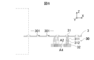
- FIG. 6 is an enlarged side view of a modified example of the hitch feeder 30.
- FIG. 3 shows a cross-section of the press device 2 cut parallel to the YZ plane shown in FIG. 1.
- FIG. 4 the parts of the press device 2 when the crankshaft 26 rotates to the bottom dead center are shown by solid lines, and the parts of the press device 2 when the crankshaft 26 rotates to the top dead center are shown by two-dot chain lines. Furthermore, hatching is omitted in FIG. 3 and FIG. 4.
- the conveying device 1A is installed on the press device 2 and feeds the metal strip 3 to be processed in the longitudinal direction into the press device 2.
- the conveying device 1A is equipped with an uncoiler 10 that pulls out one end of the metal strip 3 from the coil 4, tensioners 21-23 that tension the metal strip 3 pulled out from the uncoiler 10, and a hitch feeder 30 that pulls out the metal strip 3 that has been passed between the dies 25 of the press device 2 and sends it out of the press device 2.
- the coil 4 is formed by winding up the metal strip 3.
- the uncoiler 10 unwinds the coil 4, thereby pulling out one end of the metal strip 3 from the coil 4.
- the metal strip 3 is passed through a leveler 13 equipped with a pair of pinch rolls 11, 12 located downstream of the uncoiler 10, i.e., on the right side. This reduces distortion of the metal strip 3.
- the metal strip 3 After passing through the leveller 13, the metal strip 3 is pulled out onto the stage 24 downstream of the press device 2, i.e., on the left side of the press device 2.
- the stage 24 has a flat and horizontal stage surface, which supports the metal strip 3 and prevents it from bending.
- Tensioners 21-23 are provided on the stage 24, and the metal strip 3 is sandwiched between the tensioners 21-23 and the stage 24.
- the stage 24 is also called the transport base, as it is the foundation of the transport device 1A.
- the tensioners 21-23 apply tension to the metal strip 3 by contacting the upper surface of the metal strip 3.
- each of the tensioners 21-23 is formed in a rectangular parallelepiped shape.
- the tensioners are made of a material that is less hard than the material of the metal strip 3, such as felt or rubber.
- the tensioners 21-23 are arranged with the bottom surface of the rectangular parallelepiped facing downward.
- the tensioners 21-23 are connected to piston rods 212, 222, and 232 provided in air cylinders 211, 221, and 231 that extend from the top toward the tensioners 21-23.
- the tensioners 21-23 are pressed by the piston rods 212, 222, and 232 to press the metal strip 3 against the stage 24 and tension the metal strip 3. In this way, tensioners 21-23 eliminate deflection in metal strip 3.
- tensioners 21-23 the force applied to the metal strip 3, i.e., the pressing force, is adjusted by the vertical movement of piston rods 212, 222, 232 by air cylinders 211, 221, 231, respectively. In this way, tensioners 21-23 adjust the tension generated in the metal strip 3. This tension adjustment adjusts the inertial force when the metal strip 3 is fed by the hitch feeder 30. The details of tension adjustment will be described later.
- the tensioners 21-23 are oriented such that the longitudinal direction of the rectangle when viewed from the front faces the left-right direction, i.e., the Y direction. In this orientation, the tensioners 21-23 are arranged in the Y direction. As a result, when the metal strip 3 is fed, the tensioners 21-23 press the entire metal strip 3 in the Y direction, applying friction to the entire metal strip 3 in the Y direction. The metal strip 3 is passed through the press device 2 with any deflection removed by the tensioners 21-23.
- the press device 2 has a die 25, as shown in Figures 1, 3, and 4. As shown in Figures 3 and 4, the press device 2 also has a crankshaft 26 that converts the rotational motion of the prime mover into reciprocating motion, and a slide 28 that moves up and down in conjunction with the rotational motion of the crankshaft 26 by a connecting rod 27 connected to the crankshaft 26.
- the upper die of the die 25 moves relative to the lower die due to the up and down movement of the slide 28.
- a metal strip 3 is passed between the upper side and the lower die of the die 25, and the press device 2 presses the metal strip 3 by the up and down movement of the slide 28.
- the press device 2 forms each part of the fins of the heat exchanger.
- the press device 2 forms a through hole 301 shown in Figure 5 that has a burring portion.
- the hitch feeder 30 sequentially feeds the metal strip 3 a fixed distance for each press process in order to form the through holes 301 one after another.
- the hitch feeder 30 has a pin 31 for insertion into a through hole 301 formed in the metal strip 3 by the press device 2, and a movable block 32 that moves the pin 31 while the pin 31 is inserted into the through hole 301 to feed the metal strip 3, as shown in FIG. 5.
- the pin 31 has a cylindrical shape with an inclined tip surface and an outer diameter smaller than the diameter of the through hole 301 to facilitate easy insertion into the through hole 301.
- the pin 31 is loosely inserted into a cylindrical portion 311 that extends in the vertical direction. This allows the pin 31 to be held in the cylindrical portion 311 with its axis facing in the vertical direction.
- the lower end of the cylindrical portion 311 is closed, and a compression coil spring 312 is housed in the internal space of the cylindrical portion 311.
- the lower end of the pin 31 is supported by the compression coil spring 312 by being loosely inserted into the cylindrical portion 311.
- the tip, i.e., the upper end, of the pin 31 can be moved up and down by expanding and contracting the compression coil spring 312.
- the lower end of the cylindrical portion 311 is fixed to the upper surface of the movable block 32.
- the movable block 32 is positioned so that the left-right position of the axis of the pin 31, i.e., the Y position of the axis of the pin 31, coincides with the Y position of the center of the through-hole 301 formed in the metal strip 3.
- the movable block 32 can be moved back and forth in the up-down and back-forth directions, i.e., in the Z and X directions, at this Y position by a drive device, not shown.
- the movable block 32 moves a certain distance in the +Z direction as shown by the arrow A1 in FIG. 5 from a position where the upper end of the pin 31 is separated from the lower surface of the metal strip 3.
- the movable block 32 presses the upper end of the pin 31 against the lower surface of the metal strip 3, and compresses the compression coil spring 312 by the pin 31, so that the pin 31 is biased by the elastic force of the compression coil spring 312.
- the movable block 32 moves in the +X direction by a stroke distance greater than the pitch of the through holes 301 of the metal strip 3.
- the compression coil spring 312 biases the pin 31 in the +Z direction, so that the pin 31 enters the through hole 301.
- the movable block 32 moves further in the +X direction to feed the metal strip 3 in the +X direction.
- the movable block 32 moves the above-mentioned fixed distance in the -Z direction as shown by arrow A3, and removes the pin 31 from the through-hole 301.
- the movable block 32 then moves the above-mentioned stroke in the -X direction as shown by arrow A4, and returns to its original position.
- the movable block 32 repeats this operation every time the press device 2 performs press processing.
- the conveying device 1A intermittently feeds the metal strip 3 in the +X direction.
- the movable block 32 may be reciprocated in the X direction as shown in FIG. 6 by a drive device (not shown). Even with this configuration, the movable block 32 can insert the pin 31 into the through hole 301 to intermittently feed the metal strip 3 in the +X direction.
- the magnitude of the inertia at this time changes depending on various conditions such as the variation in the plate thickness of the metal strip 3 and the friction of the tensioners 21-23.
- the distance by which the metal strip 3 is fed i.e., the feed length
- the metal strip 3 may climb over the pin 31 due to inertial force, resulting in the feed length being longer than the intended feed length.
- the conveying device 1A is equipped with a controller 40A that controls the pressing force of the tensioners 21-23 on the metal strip 3 in order to feed the metal strip 3 by a constant feed length with high precision.
- a controller 40A that controls the pressing force of the tensioners 21-23 on the metal strip 3 in order to feed the metal strip 3 by a constant feed length with high precision.
- FIG. 7 is a hardware configuration diagram of the controller 40A provided in the transport device 1A.
- FIG. 8 is a block diagram of the controller 40A. Note that, for ease of understanding, FIGS. 7 and 8 also show the configuration of the connection destination of the controller 40A.
- the controller 40A is equipped with a computer including a CPU (Central Processing Unit) 41 and a memory 42 composed of a ROM (Read-Only Memory) and a RAM (Random Access Memory).
- the memory 42 has a feed length data storage unit 43, a set length data storage unit 44, and an angle data storage unit 45, which are described later and are shown in FIG. 8.
- the controller 40A performs various processes to control each component of the conveying device 1A by the CPU 41 reading various programs stored in the ROM of the memory 42 into the RAM and executing them.
- the controller 40A controls the above-mentioned drive unit (not shown) of the hitch feeder 30 by the CPU 41 executing a hitch feeder drive program.
- the controller 40A also controls the pressing force of the above-mentioned tensioners 21-23 by the CPU 41 executing a tensioner control program.
- the controller 40A has an I/O port (Input/Output Port) 46.
- the I/O port 46 is electrically connected to the control unit 5 provided in the press device 2 in order to obtain drive information for the press device 2.
- the I/O port 46 is also electrically connected to a length measurement sensor 50 that measures the feed length of the metal strip 3 in order to control the pressing force of the tensioners 21-23, and electro-pneumatic regulators 213, 223, and 233 that adjust the air pressure of the air cylinders 211, 221, and 231 described above.
- the control unit 5 controls each part of the press device 2.
- the control unit 5 transmits data on the rotation angle of the crankshaft 26 relative to the reference position when the crankshaft 26 rotates to the CPU 41.
- the control unit 5 transmits data on the rotation angle of the crankshaft 26 to the CPU 41 when the rotation angle at the top dead center is set to 0°.
- the control unit 5 transmits data on the rotation angle of the crankshaft 26 to the CPU 41 when the angle at which the crank pin 262 is directly above D relative to the axis A of the main shaft 261 shown in FIG. 4 is set to 0°, and the clockwise rotation C shown in FIG. 4 is set to positive rotation.
- the control unit 5 periodically transmits such data via the I/O port 46. As a result, the control unit 5 transmits press state information and transport timing information to the CPU 41.
- the pressed state refers to a state in which the pressing members provided in the press device 2, such as the crankshaft 26 and slide 28 described above, are in a specific position and orientation.
- the pressed state refers to a state in which the crankshaft 26 provided in the press device 2 is at a specific rotation angle.
- the length measuring sensor 50 is provided to measure the feed length of the metal strip 3. More specifically, the length measuring sensor 50 is fixed to a gate-shaped holder (not shown). As shown in FIG. 1, the length measuring sensor 50 is disposed on a portion of the metal strip 3 that is above the stage 24 and between the tensioners 21-23 of the metal strip 3 and the press device 2. Although not shown, the length measuring sensor 50 includes a light source that irradiates light onto the object to be measured, a line sensor that receives light reflected by the object to be measured and periodically generates image data, and a calculation unit that performs matching processing on the image data periodically generated by the line sensor to determine the displacement and speed of the object to be measured.
- the length measuring sensor 50 By being disposed at the above position, the length measuring sensor 50 periodically measures the displacement and speed of a portion of the metal strip 3 below the length measuring sensor 50. After measuring the displacement and speed of the portion of the metal strip 3, the length measuring sensor 50 transmits the displacement and speed data to the CPU 41 via the I/O port 46.
- the electro-pneumatic regulators 213, 223, and 233 adjust the air pressure in the air cylinders 211, 221, and 231 shown in FIG. 1 according to commands from the CPU 41.
- the electro-pneumatic regulators 213, 223, and 233 press the tensioners 21-23 against the metal strip 3 with a pressing force according to the commands from the CPU 41, and adjust the frictional force when the metal strip 3 is fed.
- the controller 40A is electrically connected to such devices and equipment, and performs the first tensioner control process, which controls the pressing force of the tensioners 21-23 described above, using data obtained from those devices and equipment.
- the controller 40A has various blocks configured as software shown in FIG. 8. In detail, the controller 40A has a feed length measurement unit 47 and a tensioner control unit 48.
- the feed length measuring unit 47 receives data on the rotation angle of the crankshaft 26 periodically sent from the control unit 5 of the press device 2.
- the feed length measuring unit 47 also receives data on the displacement and speed of the metal strip 3 periodically sent from the length measuring sensor 50.
- the feed length is calculated as the distance that the metal strip 3 has actually been fed between the previous specific angle and the current specific angle each time the crankshaft 26 rotates to a specific angle. This allows the feed length measuring unit 47 to obtain the feed length per press operation cycle each time the press device 2 performs press processing.
- the feed length measuring unit 47 then transmits the obtained feed length data to the tensioner control unit 48.
- the tensioner control unit 48 receives the feed length data sent from the feed length measurement unit 47. Meanwhile, the set length data storage unit 44 stores data on the ideal feed length that the metal strip 3 should be fed per one cycle of the press operation, i.e., the set length data.
- the tensioner control unit 48 reads out the set length data from the set length data storage unit 44, and calculates the deviation of the actual feed length from the set length based on the feed length data received from the feed length measurement unit 47 and the read set length. Based on the calculated deviation, the tensioner control unit 48 also determines the air pressure of the air cylinders 211, 221, and 231 that realizes the pressing force of the tensioners 21-23 to reduce the deviation. The tensioner control unit 48 calculates this air pressure every time data on the feed length per cycle is sent from the feed length measurement unit 47.
- the tensioner control unit 48 sends a signal corresponding to the determined air pressure to the electro-pneumatic regulators 213, 223, 233, causing the electro-pneumatic regulators 213, 223, 233 to adjust the air pressure in the air cylinders 211, 221, 231.
- the tensioner control unit 48 adjusts the air pressure in the air cylinders 211, 221, 231 shown in Figures 1 and 2 to the determined air pressure.
- the tensioner control unit 48 presses the tensioners 21-23 against the metal strip 3 with a pressing force that reduces the deviation. This allows the metal strip 3 to be fed a constant feed length with high precision.
- FIG. 9 is a flowchart of the first tensioner control process performed by the controller 40A of the conveying device 1A.
- a start button (not shown) provided on the press device 2 is pressed. This starts the press device 2. Furthermore, the transfer device 1A is started by the output of the control unit 5 of the press device 2.
- the controller 40A provided in the conveying device 1A first executes a tensioner control program (not shown) by the CPU 41 shown in FIG. 7, and as a result, the flow of the first tensioner control process shown in FIG. 9 is started.
- the movable block 32 of the hitch feeder 30 begins to operate due to a drive device (not shown). Furthermore, the length measurement sensor 50 is activated. On the other hand, when the press device 2 is activated, the press device 2 begins to rotate the crankshaft 26 described above for press processing.
- Figure 10 shows the relationship between the rotation angle of the crankshaft 26 of the press device 2, the feed length and speed of the metal strip 3, etc. after the conveying device 1A and the press device 2 are activated.
- Figure 10 is a graph showing an example of the changes in the position of the slide 28 of the press device 2, the total feed length of the metal strip 3 by the conveying device 1A, the feed speed of the metal strip 3 by the conveying device 1A, and the pressing force of the tensioners 21-23.
- the total feed length of the metal strip 3 in FIG. 10 refers to the length that the hitch feeder 30 has sent to the press device after the length measuring sensor 50 has been activated.
- the total feed length refers to the cumulative length measured after the length measuring sensor 50 has been activated.
- the rotation angle of the crankshaft 26 of the press device 2 repeats the cycle of 0°, 90°, 180°, 270°, then back to 0°, 90°, 180°, and so on.
- the horizontal axis of the graph would normally indicate time, but to make it easier to understand, the horizontal axis of the graph indicates the rotation angle of the crankshaft 26 of the press device 2.
- the slide 28 reciprocates in response to the rotation of the crankshaft 26.
- the slide 28 of the press device 2 reciprocates to reach top dead center P1 when the rotation angle of the crankshaft 26 is 0°, and to reach bottom dead center P2 when the rotation angle of the crankshaft 26 is 180°.
- the feed speed of the metal strip 3 reaches a maximum value at a rotation angle of 0°, where the crankshaft 26 is at top dead center P1, and reaches 0 at a rotation angle of the crankshaft 26 of 90°-270°.
- the total feed length of the metal strip 3 increases at a rotation angle of the crankshaft 26 of 270°-90°, and remains constant at a rotation angle of 90°-270°.
- the control unit 5 periodically transmits data on the rotation angle of the crankshaft 26 described above to the feed length measuring section 47 of the controller 40A.
- the length measuring sensor 50 periodically measures the displacement and speed of the metal strip 3.
- the displacement here refers to the total feed length described above. Hereinafter, this will be referred to as the total feed length.
- the length measuring sensor 50 transmits the measured total feed length and speed data to the feed length measuring section 47 of the controller 40A each time a measurement is taken.
- the feed length measurement unit 47 of the controller 40A receives rotation angle data of the crankshaft 26 from the control unit 5 of the press device 2 (step S1).
- the feed length measurement unit 47 determines whether the received rotation angle data of the crankshaft 26 is a specific angle (step S2).
- the specific angle refers to the rotation angle ⁇ a of the crankshaft 26 shown in FIG. 10, which is the rotation angle ⁇ a of the crankshaft 26 immediately before the slide 28 of the press device 2 moves from bottom dead center P2 toward top dead center P1 and the hitch feeder 30 starts to feed the metal strip 3.
- step S2 the specific angle data is stored in the angle data storage unit 45 shown in FIG. 8.
- the feed length measurement unit 47 reads the specific angle data from the angle data storage unit 45 and uses the data to determine whether the received rotation angle data of the crankshaft 26 is a specific angle.
- step S2 If the feed length measurement unit 47 determines that the rotation angle data is not a specific angle (No in step S2), it returns to step S1. Then, it waits until the next rotation angle data of the crankshaft 26 is transmitted. As a result, the feed length measurement unit 47 repeats steps S1 and S2 until it receives rotation angle data of the crankshaft 26 that is a specific angle.
- the length measuring sensor 50 periodically transmits data on the total feed length and speed of the metal strip 3.
- the feed length measuring unit 47 periodically receives the data on the total feed length and speed of the metal strip 3.
- the feed length measuring unit 47 determines that the rotation angle data is a specific angle (Yes in step S2), it determines that the total feed length received immediately after the data it periodically receives is the current total feed length (step S3).
- the feed length measurement unit 47 stores the current total feed length in the feed length data storage unit 43 in a later step. As a result, the previous total feed length before the current total feed length is stored in the feed length data storage unit 43. Following step S3, the feed length measurement unit 47 reads out the previous total feed length from the feed length data storage unit 43 (step S4).
- the feed length measurement unit 47 subtracts the previous total feed length value read in step S4 from the current total feed length value obtained in step S3 to calculate the feed length from the previous specific angle (step S5).
- the feed length measuring unit 47 calculates the feed length from the previous specific angle, it reads the set length data from the feed length data storage unit 43 and subtracts the read set length value from the calculated value of the feed length from the previous specific angle to calculate the deviation from the set length (step S6).
- the feed length measuring unit 47 transmits the calculated deviation data to the tensioner control unit 48. After calculating the deviation or transmitting the deviation data, the feed length measuring unit 47 stores the current total feed length in the feed length data storage unit 43.
- the tensioner control unit 48 adjusts the electropneumatic regulators 213, 223, and 233 based on the deviation received from the feed length measurement unit 47 (step S7).
- An example of this adjustment method is shown in Figure 11.
- FIG 11 is a conceptual diagram of the PID control (Proportional Integral Differential Controller) that the tensioner control unit 48 uses to adjust the electro-pneumatic regulators 213, 223, and 233.
- PID control Proportional Integral Differential Controller
- the tensioner control unit 48 uses the PID control shown in FIG. 11. In this case, the set feed length is x(t), the feed length in step S5 is x'(t), and the deviation in step S6 is e(t). These data are applied to the PID control to obtain the pressure value of the electropneumatic regulators 213, 223, and 233, which is the manipulated variable u(t). The tensioner control unit 48 then adjusts the electropneumatic regulators 213, 223, and 233 to the obtained pressure value. As a result, the tensioner control unit 48 sets the air pressure of the air cylinders 211, 221, and 231 shown in FIG. 1 and FIG.
- the metal strip 3 is fed by a fixed feed length with high accuracy.
- the air cylinders 211, 221, and 231 described above are an example of a pressing device as defined in this disclosure.
- the feed length measuring unit 47 of the controller 40A is an example of a measuring unit as defined in this disclosure.
- the tensioner control unit 48 of the controller 40A is an example of a control unit as defined in this disclosure.
- the slide 28 of the press device 2 is an example of a slide mechanism as defined in this disclosure.
- the state in which the crankshaft 26 of the press device 2 is oriented at a specific angle, i.e., the rotation angle ⁇ a shown in FIG. 10, is an example of the press device being in a specific pressing state as defined in this disclosure.
- the controller 40A determines the deviation between the actual feed length and the set length of the metal strip 3, and controls the tensioners 21-23 to press against the metal strip 3 with a pressing force based on the deviation. Therefore, the controller 40A can feed the metal strip 3 with high accuracy even without correction information for the metal strip 3.
- the controller 40A presses the tensioners 21-23 against the metal strip 3 with a pressing force based on the deviation between the actual feed length and the set length, so the conveying device 1A can feed the metal strip 3 with high precision even if various conditions such as the thickness and friction of the metal strip 3 change.
- one length measuring sensor 50 described in the first embodiment is provided at the center in the width direction of the metal strip 3, i.e., at the center in the Y direction.
- one length measuring sensor 50 is provided at each end in the Y direction of the metal strip 3.
- a device composed of air cylinders 211, 221, 231 and electro-pneumatic regulators 213, 223, 233 is described as an example of a pressing device.
- the pressing device may be a device having a configuration other than the above.
- the pressing device may be composed of an elastic member, such as a compression spring, which biases the tensioner 21-23 by elastically deforming, and a prime mover, such as a servo motor, which elastically deforms the elastic member by pressing the elastic member.
- the response is slow, and when the processing speed of the press device 2 is high, the pressing control of the tensioner 21-23 against the metal strip 3 may not be able to follow sufficiently.
- the pressing device has the above-mentioned configuration of compression springs and servo motors, the response is fast and it can follow sufficiently even when the processing speed of the press device 2 is high.
- the controller 40A receives data on the rotation angle of the crankshaft 26 from the control unit 5 of the press apparatus 2, and determines the time when the crankshaft 26 reaches a specific angle. In other words, it determines the timing when the press apparatus 2 reaches a specific press state. The controller 40A then determines the feed length of the metal strip 3 from the previous specific press state to the current specific press state, i.e., the feed length of one cycle, from that timing.
- the controller 40A is not limited to this.
- the controller 40A may also determine the timing when the press apparatus 2 reaches a specific press state from other data, and determine the feed length of one cycle.
- the controller 40B determines the timing at which the press device 2 enters a specific pressing state from the speed data of the metal strip 3 sent by the length measurement sensor 50.
- the speed of the metal strip 3 reaches a peak value each time the slide 28 of the press device 2 shown in the graph of "Position of slide of press device” in FIG. 10 reaches top dead center P1, i.e., each time the rotation angle of the crankshaft 26 of the press device 2 reaches 0°.
- the controller 40B provided in the conveying device 1B according to the second embodiment uses threshold data to determine whether the speed of the metal strip 3 has reached its peak value.
- the configuration of the controller 40B is shown in FIG. 12.
- FIG. 12 is a block diagram of the controller 40B provided in the transport device 1B according to the second embodiment.
- the controller 40B includes a threshold data storage unit 49 in which the threshold data for the above judgment is stored.
- the controller 40B receives data on the total feed length and speed of the metal strip 3 from the length measurement sensor 50, it reads the threshold data from the threshold data storage unit 49 and judges whether the received speed value exceeds the read threshold value to judge whether the speed has reached its peak value. By repeating this judgment, the controller 40B obtains the times T1, T2, etc. shown in the graph of "Feed speed of metal strip" in FIG. 10 at which the speed has reached its peak value.
- the controller 40B shown in FIG. 12 stores the total feed length and speed data in the feed length data storage unit 43 every time it receives the total feed length and speed data of the metal strip 3 from the length measurement sensor 50. As a result, the controller 40B stores the past total feed length and speed data for a certain period of time in the feed length data storage unit 43. Each time the controller 40B obtains new times T1, T2, ... and calculates time Ta, it uses the data stored in the feed length data storage unit 43 to calculate the total feed length of the metal strip 3 at the time Ta.
- the controller 40B determines the feed length of the metal strip 3 per cycle from the total feed length of the metal strip 3 at the latest time Ta and the total feed length of the metal strip 3 at the previous time Ta. In this way, the controller 40B calculates the feed length referred to in step S5 in the flowchart of FIG. 9 described in the first embodiment.
- the controller 40B performs control to press the tensioners 21-23 against the metal strip 3 with a pressing force that reduces the deviation by performing each step from step S6 onwards in that flowchart. As a result, the metal strip 3 is fed a constant feed length with high accuracy.
- the length measuring sensor 50 provided in the above-mentioned conveying device 1B is an example of a length measuring unit and a speed measuring unit as defined in this disclosure.
- the controller 40B is an example of a calculation unit as defined in this disclosure.
- the length measuring unit is also referred to as a total feed length measuring unit.
- the calculation unit is also referred to as a feed length calculation unit.
- the controller 40B determines the most recent time Ta at which the rotation angle of the crankshaft 26 reached a specific angle and the time Ta immediately preceding that from the speed of the metal strip 3, and determines the feed length of the metal strip 3 after the rotation angle of the crankshaft 26 reached a specific angle. Therefore, there is no need to periodically receive data on the rotation angle of the crankshaft 26 from the control unit 5 of the press device 2. As a result, as shown in FIG. 12, the controller 40B can control the air cylinders 211, 221, and 231 independently, without being connected to the control unit 5.
- the conveying device 1B determines the time Ta at which the rotation angle of the crankshaft 26 reaches a specific angle from the speed of the metal strip 3, but the control unit 5 of the press device 2 may output a specific angle signal when the rotation angle of the crankshaft 26 reaches a specific angle. Then, the conveying device 1B may determine the deviation by subtracting the total feed length immediately after the previous specific angle signal from the total feed length obtained immediately after the specific angle signal.
- the metal strip 3 is simply pressed and tensioned by the tensioners 21-23, and the tension is not measured to what degree the metal strip 3 is tensioned.
- the conveying devices 1A and 1B may further include a tension measuring device that measures the tension of the metal strip 3.
- the conveying device 1C is provided with a tension measuring device 60 that is provided between the tensioner 21-23 and the press device 2 and measures the tension of a portion of the metal strip 3 against which the tensioner 21-23 is pressed.
- FIG. 13 is a right side view of the conveying device 1C according to the third embodiment.
- FIG. 14 is an enlarged side view of the tension measuring device 60 provided in the conveying device 1C.
- FIG. 15 is a front view of the movable roll 63 provided in the tension measuring device 60. Note that hatching has been omitted in FIG. 15 to facilitate understanding. Also, the metal strip 3 has been omitted.
- the tension measuring device 60 is provided between the tensioners 21-23 and the press device 2. As a result, the tension measuring device 60 measures the tension of the metal strip 3 applied by the tensioners 21-23.
- the tension measuring device 60 has a pair of fixed rolls 61, 62 and a movable roll 63 provided between the fixed rolls 61, 62.
- the tension measuring device 60 further has a load cell 64 that measures the force applied to the movable roll 63.
- the fixed rolls 61 and 62 are arranged apart in the X direction and at the same height in the Z direction.
- the positions of the axes 65 and 66 of the fixed rolls 61 and 62 are fixed.
- the metal strip 3 is wrapped around the fixed rolls 61 and 62 from the +Z side. As a result, the metal strip 3 is stretched between the fixed rolls 61 and 62.
- the movable roll 63 is disposed between the fixed rolls 61 and 62 in the X direction and further in the -Z direction than the fixed rolls 61 and 62.
- the metal strip 3 is wrapped around the movable roll 63 from the -Z side. As a result, the movable roll 63 abuts against the metal strip 3 from the +Z side.
- the movable roll 63 has an axis 67 held by a holder 68 that can move a fixed distance in the Z direction.
- a load cell 64 is provided on the -Z side of the holder 68, and measures the force applied to the holder 68, which is linked to the movable roll 63. In this way, the load cell 64 measures the force due to the tension of the metal strip 3.
- the load cell 64 transmits the measurement data to the tensioner control unit 48 described in the first embodiment.
- the tensioner control unit 48 calculates the tension T from the measurement value received from the load cell 64 using the following formula 4.
- the tensioner control unit 48 compares the received value of tension T with a threshold value stored in a tension threshold memory unit (not shown), and if the value of tension T is greater than the threshold value, outputs an alarm signal to an alarm (not shown). Alternatively, it reduces the air pressure in the air cylinders 211, 221, and 233 by a set value. In this way, the tensioner control unit 48 monitors whether there is an abnormality in the metal strip 3. Alternatively, if it determines that there is an abnormality in the tension of the metal strip 3, it reduces the tension.
- the conveying device 1C is equipped with a tension measuring device 60 that measures the tension of the metal strip 3, so that abnormalities in the conveying device 1C and the press device 2 can be monitored from the tension of the metal strip 3.
- the conveying device 1D according to the fourth embodiment is equipped with an auxiliary tensioner 70 between the tensioners 21-23 and the press device 2.
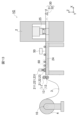
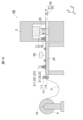
- FIG. 16 is a right side view of the conveying device 1D according to embodiment 4.
- the conveying device 1D is provided with an auxiliary tensioner 70 at the entrance of the press device 2 for the metal strip 3, i.e., the entrance on the -X side.
- the auxiliary tensioner 70 is formed in the same shape as the tensioners 21-23 described in the first embodiment, and is disposed in the same manner except for the X position. And, like the tensioners 21-23, the auxiliary tensioner 70 is pressed against the metal strip 3 by an air cylinder 71 and a piston rod 72.
- auxiliary tensioner 70 applies pressure while press device 2 is performing press processing.
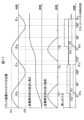
- Figure 17 shows the changes in the pressure forces of tensioners 21-23 and auxiliary tensioner 70.
- FIG. 17 is a graph showing an example of the transitions of the position of the slide 28 of the press device 2, the total feed length of the metal strip 3 by the conveying device 1D, the feed speed of the metal strip 3 by the conveying device 1D, and the pressing force of the tensioners 21-23 and the auxiliary tensioner 70 on the metal strip 3.
- the rotation angle ⁇ b of the crankshaft 26 shown in FIG. 17 is the rotation angle of the crankshaft 26 when the slide 28 of the press device 2 moves from the top dead center P1 to the bottom dead center P2 and slightly before the hitch feeder 30 finishes feeding the metal strip 3.
- the hitch feeder 30 inserts the pin 31 into the through hole 301 formed in the metal strip 3, and moves the pin 31 in this state to feed the metal strip 3.
- the hitch feeder 30 when the feed speed of the metal strip 3 shown in FIG. 17 is increased in accordance with an increase in the processing speed in the press device 2, the acceleration also increases, and the inertial force also increases.
- the pin 31 hits the inner wall of the through hole 301 hard, and a large stress is applied to the peripheral portion of the through hole 301. This may cause the through hole 301 to deform.
- the hitch feeder 30 stops the metal strip 3 after feeding the metal strip 3 at high speed for intermittent feeding, a large inertial force is applied to the metal strip 3, and as a result, the through hole 301 may be deformed by the pin 31.
- Such deformation of the through hole 301 is particularly likely to occur when the thickness of the metal strip 3 is small, for example, 0.05-0.50 mm.
- the auxiliary tensioner 70 is pressed from when the feed speed starts to decrease until before the feed speed starts to increase after the feed speed becomes 0, as shown in the graph of "Feed speed of metal strip 3" in FIG. 17.
- the auxiliary tensioner 70 is pressed from when the crankshaft 26 is at a rotation angle ⁇ b, which is the state before the press processing, to when the crankshaft 26 is at a rotation angle ⁇ c, which is the state after the press processing.
- the force with which the auxiliary tensioner 70 is pressed against the metal strip 3 is, for example, 50% of the force with which the tensioners 21-23 are pressed against the metal strip 3.
- the force with which the tensioners 21-23 are pressed against the metal strip 3 is adjusted by the tensioner control unit 48, as described in embodiment 1.
- the forces F1, F2 with which the auxiliary tensioner 70 is pressed against the metal strip 3 are, for example, 50% of the pressing forces F3, F4 of the tensioners 21-23 immediately before the auxiliary tensioner 70 starts pressing against the metal strip 3.
- the metal strip 3 is pressed by both the tensioners 21-23 and the auxiliary tensioner 70 with a force greater than the pressing force of the tensioners 21-23 alone, as shown by the solid line in the "Pressing Force” graph in Figure 17, during the period from when the crankshaft 26 is at rotation angle ⁇ b to when it is at rotation angle ⁇ c.
- This allows the auxiliary tensioner 70 to prevent the through hole 301 from being deformed by the inertial force generated by the deceleration of the feed speed.
- the auxiliary tensioner 70 is pressed against the metal strip 3 from the time the feed speed of the hitch feeder 30 decelerates until it accelerates again, preventing the metal strip 3 from moving.
- the auxiliary tensioner 70 improves the accuracy of the press working.
- the conveying device 1D according to the fourth embodiment is equipped with an auxiliary tensioner 70 that holds down the metal strip 3 during press processing. Therefore, the press device 2 has high processing accuracy during press processing of the metal strip 3.
- the controllers 40A, 40B calculate a deviation between the actual feed length and the set length of the metal strip 3, and perform control to press the tensioners 21-23 against the metal strip 3 with a pressing force based on the deviation.
- the controllers 40A, 40B are not limited to this.
- the controllers 40A, 40B may control the force with which the tensioners 21-23 are pressed against the metal strip 3 by feedforward control in certain cases.
- the conveying device 1E is equipped with a controller 40E that uses feedforward control to control the force with which the tensioners 21-23 are pressed against the metal strip 3 when the processing speed of the press device 2 changes from a constant value.
- FIG. 18 is a block diagram of a controller 40E provided in the transport device 1E.
- FIG. 19 is a diagram showing an example of the configuration of a database 590 stored in a database storage unit 59 of the controller 40E.
- the controller 40E includes a feed length measuring unit 57, a tensioner control unit 58, and a database storage unit 59 to perform feedforward control when the processing speed of the press device 2 changes from a constant value.
- the feed length measuring unit 57 has the same configuration and function as the feed length measuring unit 47 described in the first embodiment. As a result, the feed length measuring unit 57 receives data on the displacement and speed of the metal strip 3 periodically transmitted from the length measuring sensor 50. The feed length measuring unit 57 transmits the received data on the speed of the metal strip 3 to the tensioner control unit 58.
- the press device 2 shown in FIG. 1 may change the processing speed during press processing, that is, the number of press processing operations per fixed time, for example, the number of press processing operations per minute.
- the press device 2 may gradually increase the processing speed immediately after the start of press processing.
- the press device 2 may gradually increase the processing speed to a fixed processing speed, and then gradually decrease the processing speed before the end of press processing.
- the control unit 5 shown in FIG. 18 sends processing speed data to the controller 40E in order to change the transport speed of the metal strip 3 by the hitch feeder 30.
- the controller 40E controls a drive device (not shown) that drives the movable block 32 of the hitch feeder 30.
- the controller 40E receives processing speed data from the control unit 5 of the press device 2, it controls the drive device (not shown) of the hitch feeder 30 based on the processing speed data.
- the controller 40E operates the movable block 32 of the hitch feeder 30 at a speed that corresponds to the processing speed data of the press device 2.
- the controller 40E changes the transport speed of the metal strip 3 by the hitch feeder 30.
- control unit 5 of the press machine 2 shown in FIG. 18 changes the above-mentioned machining speed, it outputs a machining speed change signal indicating that the machining speed is changing, and transmits the machining speed change signal to the above-mentioned tensioner control unit 58 of the controller 40E.
- the tensioner control unit 58 receives the processing speed change signal.
- the tensioner control unit 58 also receives data on the speed of the metal strip 3 from the feed length measurement unit 57.
- the tensioner control unit 58 receives a processing speed change signal, it controls the force with which the tensioners 21-23 press against the metal strip 3 based on the database stored in the database storage unit 59 and the received data on the speed of the metal strip 3.
- the database storage unit 59 stores a database 590 shown in FIG. 19.
- the database 590 stores data experimentally obtained from past processing data of the press device 2.
- the database 590 associates data sets of the material type, plate thickness, surface treatment, and processing speed of the press device 2 to be processed by the press device 2 with data on the air pressure of the air cylinders 211, 221, and 231 that has been verified by experiment to achieve an appropriate pressing force of the tensioners 21-23 under the conditions indicated by the data.
- the tensioner control unit 58 When the tensioner control unit 58 receives a processing speed change signal, it reads out the database 590 from the database storage unit 59 shown in FIG. 18. The tensioner control unit 58 also calculates the processing speed of the press device 2 from the data on the speed of the metal strip 3 received from the feed length measurement unit 57. As shown in FIG. 18, the input device 29 is connected to the controller 40E. The tensioner control unit 58 acquires data on the material type, plate thickness, and surface treatment of the material to be processed by the press device 2, which data is input from the input device 29. The tensioner control unit 58 then selects, from the data sets for each condition number contained in the read database 590, the data set that matches or is most similar to the data set consisting of the calculated processing speed and the acquired material type, plate thickness, and surface treatment.
- the tensioner control unit 58 may also calculate the ratio of the machining speed included in the data set to the calculated machining speed, and multiply the air pressure value included in the data set by the calculated ratio to obtain the air pressure, and use the obtained air pressure as the air pressure of the selected data set.
- the tensioner control unit 58 controls the electro-pneumatic regulators 213, 223, and 233 to adjust the air pressure of the air cylinders 211, 221, and 231 to the air pressure associated with the selected data set in the database 590. As a result, the tensioner control unit 58 presses the tensioners 21-23 against the metal strip 3 with a pressing force based on the database 590. As a result, the tensioner control unit 58 adjusts the frictional force when the metal strip 3 is fed. In this way, the tensioner control unit 58 feeds the metal strip 3 with high precision even when the processing speed of the press device 2 is changed.
- FIG. 20 is a flowchart of the switching process performed by controller 40E.
- FIG. 21 is a flowchart of the second tensioner control process performed by controller 40E.
- the controller 40E determines whether or not a processing speed change signal is being output from the control unit 5 of the press device 2 (step S11).
- the controller 40E determines that it has not received a machining speed change signal from the control unit 5 of the press device 2 and that no machining speed change signal has been output (No in step S11), since the machining speed of the press device 2 remains constant, it executes the first tensioner control process described in embodiment 1 (step S12). Then, the controller 40E executes a series of steps from step S1 to step S7 of the first tensioner control process shown in FIG. 9, and then returns to step S11 shown in FIG. 20. This prepares for the control unit 5 to output a subsequent machining speed change signal.
- step S13 the controller 40E receives a processing speed change signal from the control unit 5 of the press device 2 and determines that a processing speed change signal has been output (Yes in step S11), it executes the second tensioner control process shown in FIG. 21 (step S13).
- the controller 40E reads the database 590 (step S21).
- the tensioner control unit 58 of the controller 40E reads the database 590 stored in the database storage unit 59.
- the tensioner control unit 58 acquires the current speed data of the metal strip 3 (step S22).
- the feed length measurement unit 57 periodically receives the displacement and speed data of the metal strip 3 from the length measurement sensor 50, and transmits the received displacement and speed data of the metal strip 3 to the tensioner control unit 58.
- the tensioner control unit 58 acquires the most recent speed data from the received speed data of the metal strip 3 as the current speed data.
- the tensioner control unit 58 acquires the current speed data of the metal strip 3, it uses the acquired speed data of the metal strip 3 to calculate the processing speed of the press device 2 (step S23). For example, a relational expression between the speed of the metal strip 3 and the processing speed of the press device 2 is determined in advance by experiment, and the tensioner control unit 58 uses the relational expression to calculate the current processing speed of the press device 2 from the current speed data of the metal strip 3.
- the tensioner control unit 58 acquires various data input from the input device 29 (step S24).
- the various data here refers to the data for each condition contained in the data set of the database 590 read in step S21, and specifically, data on the material type, plate thickness, and surface treatment of the material to be processed by the press device 2.
- the tensioner control unit 58 acquires the various data input from the input device 29, it selects from the data sets of the database 590 read in step S21 a data set that matches or is close to the acquired various data and the machining speed calculated in step S23 (step S25). For example, if the various data input from the input device 29 indicates that the material type is B, the plate thickness is 0.09, the surface treatment is normal, and the calculated machining speed is 250, then from the data sets of the database 590 shown in FIG. 19, the data set with condition number "2" is selected as the matching data set.
- the tensioner control unit 58 when the tensioner control unit 58 selects a data set, it adjusts the electro-pneumatic regulator based on the air pressure data of the selected data set (step S26). For example, if the data set selected from the data sets is the data set with condition number "2", the tensioner control unit 58 adjusts the electro-pneumatic regulator to the air pressure data value "10.0" (kgf) included in the data set with condition number "2". As a result, the tensioner control unit 58 adjusts the air pressure of the air cylinders 211, 221, and 231 to the air pressure data value of the selected data set. As a result, the tensioner control unit 58 presses the tensioners 21-23 against the metal strip 3 with an appropriate pressing force, and adjusts the frictional force when the metal strip 3 is fed. As a result, the metal strip 3 is fed with high precision.
- the tensioner control section 58 ends the second tensioner control process. Then, the process returns to step S11 of the switching process shown in FIG. 20.
- the above-mentioned processing speed change signal is an example of a signal indicating a change in the press processing speed as defined in this disclosure.
- the above-mentioned database storage unit 59 is an example of a storage unit that stores a database as defined in this disclosure.
- the controller 40E when the controller 40E receives a processing speed change signal of the press device 2, it reads out the database 590 from the database storage unit 59 and acquires the speed data of the metal strip 3 from the length measurement sensor 50. The controller 40E then determines the force with which the tensioners 21-23 are pressed against the metal strip 3 based on the read database 590 and the acquired speed data, and controls the tensioners 21-23 with the determined pressing force. Therefore, even if the processing speed of the press device 2 is changing, the conveying device 1E can adjust the pressing force of the tensioners 21-23 against the metal strip 3 and feed the metal strip 3 with high precision.
- the object to be molded by the press device 2 is a fin of a heat exchanger, but the object to be molded by the press device 2 is not limited to this.
- the object to be molded by the press device 2 may be a strip, for example, a metal strip 3.
- the conveying device 1A-1E is equipped with a hitch feeder 30, but the conveying device 1A-1E is not limited to this.
- the conveying device 1A-1E only needs to be equipped with a feed device that intermittently feeds the strip to the press device 2 by a set length each time press processing is completed. Therefore, the hitch feeder 30 may be a gripper feeder, which is such a feed device.
- a press system equipped with a press device 2 and a conveying device 1A-1E forms and conveys fin members.
- This press system may further include a cutting device that cuts the metal strip 3 in the width direction to manufacture fins.
- the manufactured fins may also be used to manufacture heat exchangers.
- control method for the conveying device 1A-1E, the press device system, and the conveying device 1A-1D is not limited to the above-described embodiment, and various modifications and substitutions can be made.
- Various embodiments of the present disclosure are described below as appendices.
- (Appendix 1) a feed device that intermittently conveys the strip to the press device by a set length each time press working is completed; a pressing device that presses a tensioner against the strip while the feed device is transporting the strip, thereby generating tension in the strip and slowing down the speed of the strip transported by the feed device; a measuring unit that measures a length of the strip actually fed by the feed device from a previous specific press state to a current specific press state every time the press device reaches a specific press state in the press processing; a control unit that calculates a deviation between an actual feed length of the strip measured by the measurement unit and the set length, and controls a force with which the pressing device presses the tensioner against the strip based on the deviation;
- a conveying device comprising: (Appendix 2) the press device includes a crankshaft that operates a slide mechanism for pressing the strip, The specific press state is a state in which the crankshaft is at a specific angle.
- the conveying device of claim 1. The measurement unit includes: a length measuring unit that periodically measures a total feed length of the strip fed by the feed device to the press device during the press working up to that point; a speed measurement unit that periodically measures the speed of the strip; a calculation unit that calculates the most recent time when the crankshaft reached the specific angle and the time immediately preceding the time from the speed measured by the speed measurement unit, and calculates the actual feed length from the total feed length at the most recent time measured by the length measurement unit and the total feed length at the time immediately preceding the time; Equipped with 3.
- the conveying device of claim 2. The control unit determines the force with which the tensioner is pressed against the band-shaped body by PID control. 4.
- a conveying device according to any one of claims 1 to 3. (Appendix 5) Further comprising a tension measuring device for measuring the tension of the strip. 5.
- a conveying device according to any one of claims 1 to 4. (Appendix 6)
- the tension measuring device is a pair of fixed rolls, the position of which is fixed on the rotation axis, around which the strip is wound from above and which support the strip from below; a movable roll that comes into contact with a portion of the strip that is wound between the pair of fixed rolls from above and moves up and down as the tension of the strip changes; a load cell for measuring the force applied by the strip to the movable roll; Equipped with The load cell outputs a measurement value to the control unit. 6.
- the press device further includes an auxiliary tensioner that contacts the strip to generate tension on the strip during a period from when the press device starts to when the press device finishes pressing.
- a conveying device according to any one of claims 1 to 6.
- (Appendix 8) a storage unit for storing a database in which data on a speed at which the feeder conveys the strip is associated with data on a pressing force of the tensioner against the strip at the speed;
- the measuring unit has a speed measuring unit that periodically measures the speed of the strip, the press device outputs a signal indicating a change in the press working speed when the press working speed changes from a constant value;
- the control unit is when the signal from the press device is received, the database is read from the storage unit, and data on the speed of the band is obtained from the speed measurement unit, and a force for pressing the tensioner against the band is determined based on the read database and the obtained speed data, thereby controlling the force; when the signal from the press device is not received, a deviation is calculated between the actual feed length of the strip measured
- a conveying device according to any one of claims 1 to 7.
- the press device A press device system comprising: (Appendix 10) a feed device that intermittently conveys the strip to the press device by a set length each time press working is completed; a pressing device that presses a tensioner against the strip while the feed device is transporting the strip, thereby generating tension in the strip and slowing down the speed of the strip transported by the feed device; a measuring unit for measuring a length of the strip fed by the feeding device;
- a method for controlling a conveying device comprising: acquiring data on the feed length of the strip from the measuring unit, and measuring the length of the strip actually fed by the feed device from a previous specific press state to a current specific press state each time the press device reaches a specific press state in the press working; determining a deviation between the actual feed length of the strip obtained in the step of measuring the actually fed length and the set length, and controlling a force with which the pressing device presses the
Landscapes
- Engineering & Computer Science (AREA)
- Mechanical Engineering (AREA)
- Advancing Webs (AREA)
- Controlling Rewinding, Feeding, Winding, Or Abnormalities Of Webs (AREA)
Priority Applications (2)
| Application Number | Priority Date | Filing Date | Title |
|---|---|---|---|
| JP2025512403A JPWO2024209735A1 (https=) | 2023-04-03 | 2023-11-21 | |
| DE112023006130.0T DE112023006130T5 (de) | 2023-04-03 | 2023-11-21 | Beförderungsgerät, Pressgerätsystem und Verfahren zum Steuern eines Beförderungsgeräts |
Applications Claiming Priority (2)
| Application Number | Priority Date | Filing Date | Title |
|---|---|---|---|
| JP2023-060464 | 2023-04-03 | ||
| JP2023060464 | 2023-04-03 |
Publications (1)
| Publication Number | Publication Date |
|---|---|
| WO2024209735A1 true WO2024209735A1 (ja) | 2024-10-10 |
Family
ID=92971635
Family Applications (1)
| Application Number | Title | Priority Date | Filing Date |
|---|---|---|---|
| PCT/JP2023/041873 Ceased WO2024209735A1 (ja) | 2023-04-03 | 2023-11-21 | 搬送装置、プレス装置システムおよび搬送装置の制御方法 |
Country Status (3)
| Country | Link |
|---|---|
| JP (1) | JPWO2024209735A1 (https=) |
| DE (1) | DE112023006130T5 (https=) |
| WO (1) | WO2024209735A1 (https=) |
Citations (10)
| Publication number | Priority date | Publication date | Assignee | Title |
|---|---|---|---|---|
| JPH081258A (ja) * | 1994-06-21 | 1996-01-09 | Rohm Co Ltd | フープ状リードフレームの搬送・位置決め方法、およびその装置 |
| JPH105904A (ja) * | 1996-01-19 | 1998-01-13 | Minster Mach Co:The | 打抜きプレスの減衰従動器ループによる制御システム |
| JPH10263714A (ja) * | 1997-03-25 | 1998-10-06 | Mitsubishi Shindoh Co Ltd | 凹凸加工装置 |
| JP2002102938A (ja) * | 2000-09-27 | 2002-04-09 | Calsonic Kansei Corp | コルゲートフィン製造装置 |
| JP2004223565A (ja) * | 2003-01-22 | 2004-08-12 | Calsonic Kansei Corp | フィードバックテンション装置 |
| JP2009000696A (ja) * | 2007-06-19 | 2009-01-08 | Keylex Corp | 成形加工装置 |
| JP2009154187A (ja) * | 2007-12-27 | 2009-07-16 | Orii & Mec Corp | 帯状材の送り装置 |
| JP2015526293A (ja) * | 2012-07-18 | 2015-09-10 | アルダー・エムペー・グループ・ネザーランド・ベーフェー | 平らな金属ブランクのエンボス加工(方法、器具、および対象物) |
| WO2017154426A1 (ja) * | 2016-03-09 | 2017-09-14 | コマツ産機株式会社 | ロールフィーダ、プレスシステム、およびフープ材搬送方法 |
| WO2020111061A1 (ja) * | 2018-11-28 | 2020-06-04 | 日本製鉄株式会社 | プレス成形品の製造方法、金属板セット、プレス装置及びプレスライン |
Family Cites Families (2)
| Publication number | Priority date | Publication date | Assignee | Title |
|---|---|---|---|---|
| JP2006122966A (ja) | 2004-10-29 | 2006-05-18 | Sankyo Mfg Co Ltd | 材料送り装置 |
| JP2023060464A (ja) | 2021-10-18 | 2023-04-28 | セイコーエプソン株式会社 | 液体吐出システム |
-
2023
- 2023-11-21 JP JP2025512403A patent/JPWO2024209735A1/ja active Pending
- 2023-11-21 DE DE112023006130.0T patent/DE112023006130T5/de active Pending
- 2023-11-21 WO PCT/JP2023/041873 patent/WO2024209735A1/ja not_active Ceased
Patent Citations (10)
| Publication number | Priority date | Publication date | Assignee | Title |
|---|---|---|---|---|
| JPH081258A (ja) * | 1994-06-21 | 1996-01-09 | Rohm Co Ltd | フープ状リードフレームの搬送・位置決め方法、およびその装置 |
| JPH105904A (ja) * | 1996-01-19 | 1998-01-13 | Minster Mach Co:The | 打抜きプレスの減衰従動器ループによる制御システム |
| JPH10263714A (ja) * | 1997-03-25 | 1998-10-06 | Mitsubishi Shindoh Co Ltd | 凹凸加工装置 |
| JP2002102938A (ja) * | 2000-09-27 | 2002-04-09 | Calsonic Kansei Corp | コルゲートフィン製造装置 |
| JP2004223565A (ja) * | 2003-01-22 | 2004-08-12 | Calsonic Kansei Corp | フィードバックテンション装置 |
| JP2009000696A (ja) * | 2007-06-19 | 2009-01-08 | Keylex Corp | 成形加工装置 |
| JP2009154187A (ja) * | 2007-12-27 | 2009-07-16 | Orii & Mec Corp | 帯状材の送り装置 |
| JP2015526293A (ja) * | 2012-07-18 | 2015-09-10 | アルダー・エムペー・グループ・ネザーランド・ベーフェー | 平らな金属ブランクのエンボス加工(方法、器具、および対象物) |
| WO2017154426A1 (ja) * | 2016-03-09 | 2017-09-14 | コマツ産機株式会社 | ロールフィーダ、プレスシステム、およびフープ材搬送方法 |
| WO2020111061A1 (ja) * | 2018-11-28 | 2020-06-04 | 日本製鉄株式会社 | プレス成形品の製造方法、金属板セット、プレス装置及びプレスライン |
Also Published As
| Publication number | Publication date |
|---|---|
| JPWO2024209735A1 (https=) | 2024-10-10 |
| DE112023006130T5 (de) | 2026-02-26 |
Similar Documents
| Publication | Publication Date | Title |
|---|---|---|
| CN102366803B (zh) | 用于矫直线缆的矫直装置以及相应的方法 | |
| US9259776B2 (en) | Manufacturing apparatus for heat exchanger fins | |
| US20040079780A1 (en) | Coil material feeding apparatus | |
| CN113165299B (zh) | 冲压成形品的制造方法、金属板集、冲压装置以及冲压生产线 | |
| CN108290203B (zh) | 辊式输送机、冲压系统、以及带状材输送方法 | |
| KR102002875B1 (ko) | 이차전지 전극 노칭 시스템 | |
| JP6611695B2 (ja) | 線材成形機及び線材送給方法 | |
| US5199469A (en) | Exterior lead forming device for semiconductor devices | |
| WO2024209735A1 (ja) | 搬送装置、プレス装置システムおよび搬送装置の制御方法 | |
| US20160221063A1 (en) | Press system | |
| CN109713860B (zh) | 绕组线制造装置及其控制方法 | |
| JP7241630B2 (ja) | 張力付与装置、金属製品の製造装置及び金属製品の製造方法 | |
| US20090293576A1 (en) | Bending method, and die and bending machine used for the bending method | |
| JP2004170388A (ja) | 隙間設定方法及びそれに用いる装置 | |
| KR102890247B1 (ko) | 판재 공급 장치 | |
| JP4953773B2 (ja) | 板材送り装置の板材リリース機構 | |
| JP7000616B1 (ja) | 曲率半径計測システムおよびそれを用いたベンディングロール | |
| US20220118496A1 (en) | Press brake | |
| TW202208093A (zh) | 張力資訊取得裝置、金屬線放電加工機及張力資訊取得方法 | |
| JP7580634B2 (ja) | 搬送装置、プレス装置システム、搬送装置の制御方法、フィンの製造方法および熱交換器の製造方法 | |
| JP2011088193A (ja) | フィーダ及びプレス機 | |
| JP2022011772A (ja) | プレス制御システム | |
| CN108227635B (zh) | 数值控制装置 | |
| JP7755441B2 (ja) | プレスシステム及びプレスシステムの制御方法 | |
| WO2025169602A1 (ja) | プレス装置およびプレス装置の制御方法 |
Legal Events
| Date | Code | Title | Description |
|---|---|---|---|
| 121 | Ep: the epo has been informed by wipo that ep was designated in this application |
Ref document number: 23932144 Country of ref document: EP Kind code of ref document: A1 |
|
| WWE | Wipo information: entry into national phase |
Ref document number: 2025512403 Country of ref document: JP |
|
| WWE | Wipo information: entry into national phase |
Ref document number: 112023006130 Country of ref document: DE |
|
| WWP | Wipo information: published in national office |
Ref document number: 112023006130 Country of ref document: DE |
|
| 122 | Ep: pct application non-entry in european phase |
Ref document number: 23932144 Country of ref document: EP Kind code of ref document: A1 |