WO2024209601A1 - コアユニットおよびコアユニットの製造方法 - Google Patents
コアユニットおよびコアユニットの製造方法 Download PDFInfo
- Publication number
- WO2024209601A1 WO2024209601A1 PCT/JP2023/014130 JP2023014130W WO2024209601A1 WO 2024209601 A1 WO2024209601 A1 WO 2024209601A1 JP 2023014130 W JP2023014130 W JP 2023014130W WO 2024209601 A1 WO2024209601 A1 WO 2024209601A1
- Authority
- WO
- WIPO (PCT)
- Prior art keywords
- conductor
- region
- core unit
- magnetic core
- core
- Prior art date
- Legal status (The legal status is an assumption and is not a legal conclusion. Google has not performed a legal analysis and makes no representation as to the accuracy of the status listed.)
- Ceased
Links
Images


Classifications
-
- H—ELECTRICITY
- H01—ELECTRIC ELEMENTS
- H01F—MAGNETS; INDUCTANCES; TRANSFORMERS; SELECTION OF MATERIALS FOR THEIR MAGNETIC PROPERTIES
- H01F17/00—Fixed inductances of the signal type
- H01F17/04—Fixed inductances of the signal type with magnetic core
- H01F17/06—Fixed inductances of the signal type with magnetic core with core substantially closed in itself, e.g. toroid
-
- H—ELECTRICITY
- H01—ELECTRIC ELEMENTS
- H01F—MAGNETS; INDUCTANCES; TRANSFORMERS; SELECTION OF MATERIALS FOR THEIR MAGNETIC PROPERTIES
- H01F37/00—Fixed inductances not covered by group H01F17/00
Definitions
- This disclosure relates to a core unit and a method for manufacturing a core unit.
- a core unit including a magnetic core is known (see, for example, Patent Document 1).
- the core unit disclosed in Patent Document 1 includes a bus bar, a pair of core members, a first core member and a second core member, and a core holding member.
- the core unit comprises a first conductor that is conductive and has a first region extending in a first direction, an insulating retaining member that contacts the first outer peripheral surface in the first region to fix the first conductor and is arranged on the outer peripheral side of the first conductor so as to surround the first outer peripheral surface, and a magnetic core that is connected in a ring shape, held by the retaining member, and arranged on the outer peripheral side of the first region via the retaining member.
- FIG. 1 is a schematic perspective view of a core unit according to a first embodiment of the present disclosure.
- FIG. 2 is a schematic cross-sectional view of the core unit shown in FIG.
- FIG. 3 is a flowchart showing typical steps of a method for manufacturing the core unit in the first embodiment.
- FIG. 4 is a schematic cross-sectional view showing a state in which the first portion is formed by the first insert molding step.
- FIG. 5 is a schematic cross-sectional view taken along line VV in FIG.
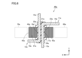
- FIG. 6 is a schematic cross-sectional view showing a state in which a plurality of nanocrystal foils are laminated.
- FIG. 7 is a schematic cross-sectional view showing a core unit in the second embodiment.
- FIG. 1 is a schematic perspective view of a core unit according to a first embodiment of the present disclosure.
- FIG. 2 is a schematic cross-sectional view of the core unit shown in FIG.
- FIG. 3 is a flowchart showing typical steps of a
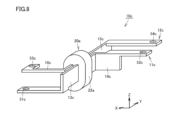
- FIG. 8 is a schematic perspective view showing a core unit according to the third embodiment.
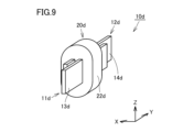
- FIG. 9 is a schematic perspective view showing a core unit according to the fourth embodiment.
- FIG. 10 is a schematic cross-sectional view showing a part of the core unit in the fourth embodiment.
- FIG. 11 is a schematic perspective view showing a core unit in the fifth embodiment.
- FIG. 12 is an exploded perspective view of the core unit according to the fifth embodiment.
- FIG. 13 is a flowchart showing typical steps of a method for manufacturing a core unit according to the fifth embodiment.
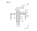
- FIG. 14 is a schematic cross-sectional view showing a state in which the first portion is formed by the first insert molding step.
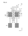
- FIG. 15 is a schematic cross-sectional view showing a process of inserting the magnetic core.
- FIG. 14 is a schematic cross-sectional view showing a state in which the first portion is formed by the first insert molding step.
- FIG. 15 is a schematic cross-sectional view showing a process of inserting the magnetic core
- FIG. 16 is a schematic cross-sectional view showing a state in which the second portion is formed by the second insert molding step.
- FIG. 17 is a schematic perspective view showing a core unit in the sixth embodiment.
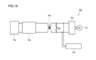
- FIG. 18 is a schematic diagram showing a core unit system including the core unit in the first embodiment.
- one of the objectives is to provide a core unit with good magnetic core characteristics.
- the core unit has good magnetic core characteristics.
- the core unit according to the present disclosure includes: (1) A first conductor having electrical conductivity and a first region extending in a first direction, an insulating retaining member that contacts a first outer surface in the first region to fix the first conductor and is arranged on the outer periphery of the first conductor so as to surround the first outer periphery, and a magnetic core that is connected in a ring shape, held by the retaining member, and arranged on the outer periphery of the first region via the retaining member.
- a retaining member arranged on the outer periphery of the first conductor fixes the first conductor, and the magnetic core is held by the retaining member. Because the magnetic cores included in the core unit are connected in a ring shape, magnetic resistance caused by air gaps in the circumferential direction does not occur. As a result, this type of core unit has good magnetic core characteristics.
- the retaining member may include a first portion disposed between the first conductor and the magnetic core, and a second portion disposed connected to the first portion and covering the magnetic core.
- the magnetic core can be sufficiently protected since the magnetic core can be covered by the second portion connected to the first portion. Therefore, the risk of damage to the magnetic core included in the core unit can be reduced.
- the second part may contact the outer peripheral surface of the magnetic core and the surface of the magnetic core located in the first direction. By doing so, there is no gap between the magnetic core and the second part that covers the magnetic core, so that, for example, when the core unit is being transported, the movement of the magnetic core is restricted within the space surrounded by the first part and the second part. This further reduces the risk of damage to the magnetic core included in the core unit.
- the first part may be made of resin.
- the second part may be made of resin.
- the heat resistance temperature of the first part may be lower than the heat resistance temperature of the second part.
- a metal foil band which is a magnetic material before sintering, is wrapped around the outer periphery of the first part, and the first part is sintered into a high temperature state while taking into account the heat resistance temperature of the first part.
- the heat resistance temperature of the second part is low, a relatively inexpensive resin with low heat resistance can be selected and used for the second part. Therefore, such a core unit can be manufactured more efficiently.
- the holding member may be arranged with a gap between it and the magnetic core. This makes it easier to hold the magnetic core manufactured in a separate process in the holding member. Therefore, such a core unit can be made more versatile in the manufacturing process.
- the magnetic core may include multiple laminated nanocrystalline foils.
- Such a magnetic core can be manufactured by wrapping the nanocrystalline foil around the outer periphery of the first part of the holding member and then sintering it. This allows the magnetic core to be positioned without any gaps in the first part, and the magnetic core can be held more stably by the holding member. Furthermore, such a magnetic core has high magnetic permeability and low temperature dependency, and therefore can achieve better characteristics.
- a second conductor may be further provided that has a second region that is conductive and extends in a first direction, the first region and the second region being arranged side by side with a gap between them and the first conductor.
- the holding member may be arranged on the outer periphery of the second conductor so as to contact the second outer peripheral surface in the second region to fix the second conductor and surround the second outer peripheral surface. In this way, the first conductor and the second conductor can be fixed with a gap between them by the holding member.
- Such a core unit can use both the first conductor and the second conductor to pass currents in opposite directions, for example, and can be effectively used as a so-called common mode noise filter.
- the holding member may be provided with a notch recessed from the outside along the first direction in the region between the first conductor and the second conductor. In this way, the creepage distance between the first conductor and the second conductor can be increased. Therefore, the insulation between the first conductor and the second conductor can be improved.
- a method for manufacturing a core unit includes the steps of preparing a first conductor having electrical conductivity and a first region extending in a first direction, arranging an insulating retaining member on the outer periphery of the first conductor so as to contact and surround the first outer periphery of the first region of the first conductor, thereby fixing the first conductor to the retaining member, wrapping a metal foil strip, which is a magnetic material, in layers around the outer periphery of the retaining member, and sintering the wrapped metal foil strip to form a magnetic core.
- the magnetic core is made by winding and sintering a metal foil strip, which is a magnetic material, in layers, making it possible to efficiently manufacture a core unit that includes a magnetic core with excellent characteristics.
- the method for manufacturing the core unit may further include a step of arranging an insulating retaining member on the outer peripheral surface of the magnetic core after the step of forming the magnetic core. In this way, it is possible to efficiently manufacture a core unit having the above-mentioned configuration that adequately protects the magnetic core.
- the method of manufacturing a core unit includes the steps of preparing a first conductor having electrical conductivity and a first region extending in a first direction, arranging an insulating retaining member on the outer periphery of the first conductor so as to contact and surround the first outer periphery of the first region of the first conductor, thereby fixing the first conductor to the retaining member, and arranging a ring of magnetic cores on the outer periphery of the first region.
- This method of manufacturing a core unit can also efficiently manufacture a core unit with the above-mentioned configuration.
- the magnetic core which is previously connected in a ring shape, can be inserted along the first direction and positioned on the outer periphery of the first conductor, so that it is possible to use a resin with low heat resistance as the retaining member, thereby improving productivity.
- the step of fixing the first conductor to the holding member may be performed by insert molding. In this way, the first conductor can be fixed to the holding member more reliably.
- FIG. 1 is a schematic perspective view of the core unit in the first embodiment of the present disclosure.
- FIG. 1 is a simplified illustration of a part of the core unit in the first embodiment, particularly a first part of a holding member described later.
- FIG. 2 is a schematic cross-sectional view of the core unit shown in FIG. 1.
- FIG. 2 is a view of the core unit shown in FIG. 1 as viewed in the direction indicated by the arrow II.
- FIG. 1 is a schematic perspective view of the core unit in the first embodiment of the present disclosure.
- the X direction indicates the direction in which a first conductor and a second conductor described later are arranged side by side
- the Y direction indicates the direction in which the first conductor and the second conductor, which are the first direction, extend.
- the X direction, the Y direction, and the Z direction are each orthogonal to each other.
- FIG. 2 is a cross-sectional view when cut in the X-Y plane.
- the core unit 10a includes a first conductor 11a, a second conductor 12a, a holding member 20a, and a magnetic core 40a. Both the first conductor 11a and the second conductor 12a are conductive.
- the first conductor 11a includes a first region 13a extending in the Y direction, which is a first direction, and a first bent portion 14a extending in the X direction from the Y direction end of the first region 13a.
- the second conductor 12a includes a second region 15a extending in the first direction, and a second bent portion 16a extending in the X direction from the Y direction end of the second region 15a.
- Both the first region 13a and the second region 15a have a shape that extends straight in the Y direction, which is the first direction.
- the first conductor 11a and the second conductor 12a are each a belt-shaped flat steel plate, for example, a copper plate, folded at 90 degrees.
- the first conductor 11a and the second conductor 12a are also called bus bars.
- the first conductor 11a is used, for example, as a P-type bus bar.
- the second conductor 12a is used, for example, as an N-type bus bar.
- the first conductor 11a and the second conductor 12a are arranged with a gap in the X direction.
- the first conductor 11a and the second conductor 12a are arranged such that the first region 13a extending in the first direction and the second region 15a extending in the first direction form parallel plates.
- magnetic fluxes can be canceled out when currents flow in opposite directions between the conductors, thereby reducing self-inductance.
- the holding member 20a is insulating.
- the holding member 20a contacts the first outer peripheral surface 17a in the first region 13a of the first conductor 11a. Specifically, the holding member 20a contacts the first outer peripheral surface 17a in the central region of the first region 13a in the first direction.
- the holding member 20a also contacts the second outer peripheral surface 18a in the second region 15a of the second conductor 12a. Specifically, the holding member 20a contacts the second outer peripheral surface 18a in the central region of the second region 15a in the first direction.
- the holding member 20a fixes the first conductor 11a and the second conductor 12a. In this case, the holding member 20a fixes the first conductor 11a and the second conductor 12a with a gap between them in the X direction.
- the holding member 20a includes a first portion 21a and a second portion 22a.
- the first portion 21a is disposed between the first conductor 11a and the magnetic core 40a and between the second conductor 12a and the magnetic core 40a.
- the first portion 21a is also disposed between the first conductor 11a and the second conductor 12a.
- the first conductor 11a and the second conductor 12a are each configured to be inserted into the holding member 20a, specifically, the first portion 21a.
- the first portion 21a includes a pair of guide portions 24a and 25a whose outer peripheral surfaces 23a protrude outwardly at an interval in the first direction.
- the guide portions 24a and 25a are formed in a ring shape.
- the first portion 21a includes an area disposed on the inner side of the magnetic core 40a between the guide portions 24a and 25a in the first direction. Guide portion 24a and guide portion 25a are used to position magnetic core 40a in the first direction.
- the second part 22a covers the magnetic core 40a.
- the second part 22a is arranged in connection with the first part 21a.
- the second part 22a includes an annular part 31a that is connected in an annular shape on the outer side of the magnetic core 40a, and a pair of flange parts 34a and 35a that are arranged at a distance in the first direction.
- the flange parts 34a and 35a are arranged to extend inward from the respective ends of the annular part 31a in the first direction.
- the inner end of the flange part 34a is in contact with the outer end of the guide part 24a.
- the inner end of the flange part 35a is in contact with the outer end of the guide part 25a.
- the magnetic core 40a is arranged in the space 29a formed by the first part 21a and the second part 22a.
- the second portion 22a is attached to cover the magnetic core 40a by insert molding, as described below.
- the first portion 21a is made of resin.
- the second portion 22a is also made of resin.
- the resin material constituting the first portion 21a is different from the resin material constituting the second portion 22a.
- the heat resistance temperature of the first portion 21a is higher than the heat resistance temperature of the second portion 22a.
- the resin material constituting the first portion 21a is a highly heat-resistant resin, specifically, for example, polypropylene.
- the resin material constituting the second portion 22a is a general resin, specifically, for example, polystyrene.
- the holding member 20a is composed of two different types of resin members.
- the magnetic core 40a is connected in a ring shape.
- the magnetic core 40a is an integral type connected in a ring shape without any cuts in the circumferential direction, and is not configured by gluing or connecting two or more circumferentially divided components that make up the magnetic core 40a.
- the magnetic core 40a is held by the holding member 20a.
- the magnetic core 40a is disposed on the outer periphery side of the first conductor 11a and the outer periphery side of the second conductor 12a via the holding member 20a.
- the inner peripheral surface 41a of the magnetic core 40a contacts the outer peripheral surface 23a of the first portion 21a of the retaining member 20a.
- the outer peripheral surface 42a of the magnetic core 40a contacts the inner peripheral surface 32a of the annular portion 31a of the second portion 22a of the retaining member 20a.
- one end face 43a of the magnetic core 40a in the first direction contacts the inner surface 26a of the guide portion 24a in the first direction of the first portion 21a and the inner surface 36a of the flange portion 34a in the first direction of the second portion 22a.
- the other end face 44a of the magnetic core 40a in the first direction contacts the inner surface 27a of the guide portion 25a in the first direction of the first portion 21a and the inner surface 37a of the flange portion 35a in the first direction of the second portion 22a.
- the second part 22a which is made of resin, is attached so as to be connected to the first part 21a by insert molding.
- the magnetic core 40a includes multiple laminated nanocrystalline foils.
- the magnetic core 40a is manufactured by sintering multiple laminated nanocrystalline foils that are wound around the circumference. This will be described later.
- Figure 3 is a flowchart showing the typical steps of the manufacturing method of the core unit 10a in embodiment 1.
- the conductor preparation step is carried out as the first step (S11).
- two conductors a first conductor 11a and a second conductor 12a, are prepared.
- a strip-shaped copper plate cut to a predetermined length in the longitudinal direction is prepared, and the first conductor 11a is bent at a 90 degree angle at a predetermined location.
- the first conductor 11a is prepared by forming a first region 13a extending in the first direction and a first bent portion 14a extending in the X direction from the end of the first region 13a in the first direction.
- the second conductor 12a is prepared by bending the strip-shaped copper plate.
- step (S12) a first insert molding step is performed.
- the first portion 21a of the holding member 20a is formed by insert molding.
- the prepared first conductor 11a and second conductor 12a are first mounted in a mold.
- the first conductor 11a is mounted so as to support the end of the first region 13a and the end of the first bent portion 14a.
- the second conductor 12a is mounted so as to support the end of the second region 15a and the end of the second bent portion 16a.
- the first region 13a of the first conductor 11a and the second region 15a of the second conductor 12a are arranged parallel to each other along the first direction with a gap therebetween.
- a part of the first region 13a of the first conductor 11a and a part of the second region 15a of the second conductor 12a are mounted so as to be arranged in the mold. Then, resin is injected and molded so that the resin constituting the first portion 21a is arranged in contact with a part of the first region 13a of the first conductor 11a and a part of the second region 15a of the second conductor 12a arranged in the mold. Specifically, the resin constituting the first portion 21a is injected and molded so as to surround the first outer peripheral surface 17a of the first conductor 11a and the second outer peripheral surface 18a of the second conductor 12a. In this manner, the first portion 21a of the holding member 20a is formed.
- FIG. 4 is a schematic cross-sectional view showing the state in which the first portion 21a is formed by the first insert molding process (first core unit preliminary body 45a).
- FIG. 4 corresponds to the cross-section shown in FIG. 2.
- FIG. 5 is a schematic cross-sectional view taken along line V-V in FIG. 4. Referring to both FIG. 4 and FIG. 5, the first portion 21a that contacts the first outer peripheral surface 17a in the first region 13a of the first conductor 11a and the second outer peripheral surface 18a in the second region 15a of the second conductor 12a to form the holding member 20a is formed by the first insert molding process. In this way, the first core unit preliminary body 45a is formed.
- the resin used is a resin that can withstand the subsequent sintering process of the nanocrystalline foil, i.e., a resin with a high heat resistance temperature.
- a resin with a high heat resistance temperature Specifically, for example, the above-mentioned polypropylene is used.
- the first insert molding process an example of the location where the first conductor 11a and the second conductor 12a are held is illustrated by areas 61a, 62a, 63a, and 64a, respectively, surrounded by thin lines. Areas 61a and 63a, and areas 62a and 64a, which are connected by double-headed arrows, may be supported by the same mold, for example. Areas 65a, 66a, 67a, and 68a, which are shown by dashed lines in FIG. 4, are areas that can be freely designed in the device or unit in which the core unit 10a is mounted.
- a nanocrystalline foil band winding process is carried out.
- a metal foil band of a magnetic material in this embodiment, a band-shaped nanocrystalline foil
- the nanocrystalline foil band is flexible, it can be wound in a ring shape without gaps.
- Figure 6 is a schematic cross-sectional view showing a state in which multiple sheets of nanocrystalline foil are stacked (second core unit preliminary body 46a).
- the second core unit preliminary body 46a multiple sheets of nanocrystalline foil 47a are stacked from the inner peripheral side to the outer peripheral side.
- the first folded portion 14a of the first conductor 11a and the second folded portion 16a of the second conductor 12a are folded at an angle of 90 degrees with respect to the first region 13a and the second region 15a, respectively, so that when the nanocrystalline foil strip is wound, the regions 69a and 70a shown by dashed lines located on both sides of the annularly wrapped nanocrystalline foil 47a in the X direction do not interfere with the first conductor 11a and the second conductor 12a.
- the first conductor 11a and the second conductor 12a having such a configuration, it is easy to automate the winding of the strip-shaped nanocrystalline foil using a specified device, for example.
- the first folded portion 14a and the second folded portion 16a may be formed after the nanocrystalline foil 47a is wound.
- step (S14) a sintering process is carried out.
- the first core unit preparatory body 45a which is made by stacking multiple sheets of nanocrystalline foil, is heated to a predetermined temperature, for example, 500°C, using, for example, an electric furnace, and maintained for a predetermined time to allow the sintering to proceed.
- a second core unit preparatory body 46a is obtained in which the nanocrystalline foil laminate has become a magnetic core.
- the second insert molding process is carried out as a process (S15).
- the second portion 22a of the holding member 20a is formed by insert molding.
- the second core unit preliminary body 46a in which the nanocrystalline foil laminate has become a magnetic core is attached to a mold.
- the first conductor 11a is attached so as to support the end of the first region 13a and the end of the first bent portion 14a.
- the second conductor 12a is attached so as to support the end of the second region 15a and the end of the second bent portion 16a.
- the outer peripheral surface 42a and both end faces 43a and 44a in the first direction of the magnetic core 40a obtained through the sintering process are arranged so as to be exposed in the mold.
- the resin constituting the second portion 22a is injected and molded so that the resin constituting the second portion 22a is arranged in contact with the outer peripheral surface 42a and both end faces 43a and 44a of the magnetic core 40a arranged in the mold.
- the resin that constitutes the second portion 22a is injected and molded so as to surround the outer peripheral surface 42a and both end faces 43a and 44a of the magnetic core 40a.
- the second portion 22a is formed so that the flanges 34a and 35a of the second portion 22a come into contact with the guide portions 24a and 25a of the first portion 21a. In this manner, the second portion 22a of the holding member 20a is formed.
- the core unit 10a in embodiment 1 shown in FIG. 2 etc. is manufactured.
- the core unit 10a is manufactured by forming the first portion 21a and the second portion 22a by an insert molding process.
- the retaining member 20a arranged on the outer periphery of the first conductor 11a fixes the first conductor 11a, and the magnetic core 40a is retained by the retaining member 20a. Since the magnetic cores 40a included in the core unit 10a are connected in a ring shape, magnetic resistance due to an air gap in the circumferential direction does not occur. As a result, the magnetic core 40a of this core unit 10a has good characteristics.
- the number of parts of the core unit is small. Furthermore, in consideration of the ease of installation in the subsequent process, the core unit is required to be compact and have improved workability during installation.
- the core unit 10a the first conductor 11a, the holding member 20a, and the magnetic core 40a are integrated.
- the second conductor 12a is also integrated. This reduces the number of parts and improves the ease of handling during installation. This improves workability.
- the core unit 10a is an integrated type, no space is required to fasten the members that make up the core unit 10a. This allows for miniaturization and space saving when installing the core unit 10a.
- Such a core unit 10a allows for a reduction in the number of parts, miniaturization, and improved workability.
- the core unit 10a includes a second conductor 12a that is conductive and has a second region 15a extending in a first direction, with the first region 13a and the second region 15a arranged side by side with a gap between them and the first conductor 11a.
- the holding member 20a contacts the second outer peripheral surface 18a in the second region 15a to fix the second conductor 12a, and is arranged on the outer peripheral side of the second conductor 12a so as to surround the second outer peripheral surface 18a.
- the first conductor 11a and the second conductor 12a can be fixed with a gap between them by the holding member 20a.
- Such a core unit 10a can use both the first conductor 11a and the second conductor 12a to pass currents in opposite directions, for example, and can be effectively used as a so-called common mode noise filter.
- the holding member 20a includes a first portion 21a that is disposed between the first conductor 11a and the magnetic core 40a, and a second portion 22a that is disposed connected to the first portion 21a and covers the magnetic core 40a. Therefore, the magnetic core 40a can be sufficiently protected because the magnetic core 40a can be covered by the second portion 22a that is connected to the first portion 21a. This reduces the risk of damage to the magnetic core 40a included in the core unit 10a.
- the first portion 21a is made of resin.
- the second portion 22a is made of resin.
- the heat resistance temperature of the first portion 21a is lower than the heat resistance temperature of the second portion 22a. Therefore, the magnetic core material before sintering, for example the above-mentioned nanocrystalline foil 47a, is wound around the outer periphery of the first portion 21a, and the magnetic core 40a can be formed by sintering the material at a high temperature while taking into account the heat resistance temperature of the first portion 21a.
- the heat resistance temperature of the second portion 22a is low, a relatively inexpensive resin with low heat resistance can be selected and used for the second portion 22a. Therefore, such a core unit 10a can be manufactured more efficiently.
- the magnetic core 40a includes multiple laminated nanocrystalline foils 47a.
- Such a magnetic core 40a can be manufactured by wrapping the nanocrystalline foil 47a around the outer periphery of the first portion 21a of the holding member 20a and then sintering it. Therefore, the magnetic core 40a can be positioned with no gaps around the first portion 21a, and the magnetic core 40a can be held more stably by the holding member 20a. Furthermore, such a magnetic core 40a has high magnetic permeability and low temperature dependency, and therefore can achieve better characteristics.
- the manufacturing method of the core unit 10a includes the steps of preparing a first conductor 11a having a conductive first region 13a extending in a first direction, arranging an insulating holding member 20a on the outer periphery of the first conductor 11a so as to contact and surround the first outer periphery 17a of the first region 13a of the first conductor 11a, and fixing the first conductor 11a to the holding member 20a, wrapping a metal foil strip, which is a magnetic material, in layers around the outer periphery of the holding member 20a, and sintering the wrapped metal foil strip to form a magnetic core 40a.
- the magnetic core 40a is made by winding and sintering a metal foil strip, which is a magnetic material, in layers, making it possible to efficiently manufacture the core unit 10a including the magnetic core 40a with excellent characteristics.
- the process of fixing the first conductor 11a to the holding member 20a is performed by insert molding. This makes it possible to more reliably fix the first conductor 11a to the holding member 20a.
- FIG. 7 is a schematic cross-sectional view showing a core unit in embodiment 2.
- Fig. 7 corresponds to the cross section shown in Fig. 2.
- the core unit 10b in embodiment 2 basically has the same configuration as in embodiment 1, and exerts the same effects.
- the core unit in embodiment 2 differs from embodiment 1 in that the configuration of the second portion is different.
- the second part 22b can be connected to the first part 21a and the magnetic core 40a can be covered without using insert molding, and the magnetic core 40a can be adequately protected. Therefore, the risk of damage to the magnetic core 40a included in the core unit 10b can be reduced.
- FIG. 8 is a schematic perspective view showing a core unit in embodiment 3.
- the core unit 10c in embodiment 3 basically has the same configuration as in embodiment 1, and achieves the same effects.
- the core unit 10c in embodiment 3 is different from embodiment 1 in that the shapes of the first conductor and the second conductor are different.
- the core unit 10c in the third embodiment includes a first conductor 11c and a second conductor 12c.
- the first conductor 11c the end of the first region 13c is extended and bent in the X direction so that the thickness direction is the Z direction.
- a through hole 51c is formed in the part near the tip, penetrating in the thickness direction.
- the end of the first bent portion 14c is extended and the thickness direction is the Z direction.
- a through hole 52c is formed in the part near the tip, penetrating in the thickness direction.
- the second conductor 12c the end of the second region 15c is extended and bent in the X direction.
- a through hole 53c is formed in the part near the tip, penetrating in the Z direction, which is the thickness direction.
- the end of the second bent portion 16c is extended and bent in the X direction so that the thickness direction is the Z direction.
- a through hole 54c is formed in the part near the tip, penetrating in the thickness direction.
- the through holes 51c, 52c, 53c, and 54c can be used to fasten to other members using bolts or the like. This makes it easier to perform later processes, such as the installation of the core unit 10c.
- FIG. 9 is a schematic perspective view showing a core unit in the fourth embodiment.
- Fig. 10 is a schematic cross-sectional view showing a part of the core unit in the fourth embodiment.
- the core unit 10d in the fourth embodiment basically has the same configuration as the first embodiment, and has the same effects.
- the core unit 10d in the fourth embodiment is different from the first embodiment in that the shapes of the first conductor, the second conductor, and the holding member are different.
- the core unit 10d in the fourth embodiment includes a first conductor 11d and a second conductor 12d.
- the first conductor 11d has a first region 13d.
- the first conductor 11d does not include the first bent portion shown in the first embodiment. That is, the first conductor 11d is configured to have a shape that extends straight along the first direction.
- the second conductor 12d has a second region 15d. Like the first conductor 11d, the second conductor 12d also does not include a second bent portion and is configured to have a shape that extends straight along the first direction. When such a shape is required for the core unit 10d, the configuration shown in Figure 9 etc. may be used.
- the holding member 20d has a notch 55d recessed from the outside along the first direction in the region between the first conductor 11d and the second conductor 12d.
- the notch 55d is formed to extend straight along the first direction. This can lengthen the creepage distance D between the first conductor 11d and the second conductor 12d, as shown by the dashed line. This can therefore improve the insulation between the first conductor 11d and the second conductor 12d.
- the notch 55d is formed to extend straight along the first direction, but is not limited thereto.
- the notch 55d may have a region that extends at an angle to the first direction, or may have a region that extends in a direction perpendicular to the first direction (X direction).
- FIG. 11 is a schematic perspective view showing a core unit in embodiment 5.
- Fig. 12 is an exploded perspective view of the core unit in embodiment 5.
- the core unit 10e in embodiment 5 basically has the same configuration as in embodiment 1, and achieves the same effects. However, the core unit 10e in embodiment 5 has a different configuration of the holding member from that in embodiment 1.
- the core unit 10e in the fifth embodiment includes a first conductor 11e and a second conductor 12e.
- the first conductor 11e has a first region 13e.
- the second conductor 12e has a second region 15e.
- the insulating retaining member 20e included in the core unit 10e includes a first portion 21e and a second portion 22e.
- the first portion 21e is disposed between the first conductor 11e and the magnetic core 40e and between the second conductor 12e and the magnetic core 40e.
- the first portion 21e includes an inner wall portion 23e, an outer wall portion 24e, and a bottom wall portion 25e.
- the inner wall portion 23e is disposed so as to surround the first outer peripheral surface 17e and the second outer peripheral surface 18e, and fixes the first conductor 11e and the second conductor 12e.
- the outer wall portion 24e is disposed on the outer periphery side with a gap from the inner wall portion 23e.
- the bottom wall portion 25e is disposed so as to connect the end portion in the first direction of the inner wall portion 23e and the end portion in the first direction of the outer wall portion 24e.
- the recessed portion 26e surrounded by the inner wall portion 23e, the outer wall portion 24e, and the bottom wall portion 25e can accommodate the annular magnetic core 40e.
- the magnetic core 40e having a through hole 47e in the first direction is accommodated in the recessed portion 26e.
- the second portion 22e is used to cover the opening of the recessed portion 26e, thereby forming the holding member 20e included in the core unit 10e in the fifth embodiment.
- Figure 13 is a flowchart showing the representative steps of the manufacturing method of the core unit 10e in embodiment 5.
- the first step (S21) is a conductor preparation step.
- this conductor preparation step two conductors, a first conductor 11e and a second conductor 12e, are prepared.
- the first conductor 11e and the second conductor 12e are formed by bending an actual copper plate, etc.
- step (S22) a first insert molding step is carried out.
- the first portion 21e of the holding member 20e is formed by insert molding.
- the first conductor 11e and the second conductor 12e are attached to a mold and molded using injection molding to have the outer shape of the first portion 21e.
- FIG. 14 is a schematic cross-sectional view showing the state in which the first portion 21e is formed by the first insert molding process (first core unit preliminary body 45e).
- FIG. 14 corresponds to the cross section shown in FIG. 2.
- the first insert molding process forms the first portion 21e of the above-mentioned shape that contacts the first outer peripheral surface 17e in the first region 13e of the first conductor 11e and the second outer peripheral surface 18e in the second region 15e of the second conductor 12e to form the holding member 20e. That is, the first portion 21e including the inner wall portion 23e, the outer wall portion 24e, and the bottom wall portion 25e is formed.
- the resin used does not include a process of raising the temperature to the sintering temperature of the magnetic core, so a resin with low heat resistance can also be used.
- a magnetic core arrangement step is performed.
- a ring-shaped magnetic core 40e is prepared and arranged on the outer periphery of the first conductor 11e and the second conductor 12e.
- the magnetic core 40e is inserted into the recess 26e to arrange the magnetic core 40e on the outer periphery of the first conductor 11e and the second conductor 12e.
- FIG. 15 is a schematic cross-sectional view showing the step of inserting the magnetic core 40e. Referring to FIG. 15, a ring-shaped magnetic core 40e is prepared separately, and as shown by the white arrow in FIG. 15, the magnetic core 40e is moved along the first direction and inserted into the recess 26e from the opening side. In this way, the magnetic core 40e is arranged in the recess 26e formed between the inner wall portion 23e and the outer wall portion 24e.
- FIG. 16 is a schematic cross-sectional view showing the state in which the second portion 22e has been formed by the second insert molding step. Specifically, referring to FIG. 16, the first core unit preliminary body 45e with the magnetic core 40e inserted therein is attached to a mold. Then, resin is injected so as to close the opening of the recess 26e, thereby forming the second portion 22e as a lid portion. In this manner, the second portion 22e of the holding member 20e is formed.
- the core unit 10e in embodiment 5 is manufactured.
- the core unit 10e is manufactured by forming the first portion 21e and the second portion 22e through an insert molding process.
- the manufacturing method of the core unit 10e includes the steps of preparing a first conductor 11e having a conductive first region 13e extending in a first direction, arranging an insulating retaining member 20e on the outer periphery of the first conductor 11e so as to contact and surround the first outer periphery 17e of the first region 13e of the first conductor 11e, and fixing the first conductor 11e to the retaining member 20e, and arranging a ring of magnetic cores 40e on the outer periphery of the first region 13e.
- This method of manufacturing the core unit 10e allows the core unit 10e with the above-described configuration to be manufactured efficiently.
- the magnetic core 40e which is previously connected in a ring shape, can be inserted along the first direction and positioned on the outer periphery of the first conductor 11e, so that it is possible to use a resin with low heat resistance as the retaining member 20e, thereby improving productivity.
- the second part 22e does not have to be manufactured by insert molding. Instead, a lid-like second part can be manufactured from a separate member, and after inserting the magnetic core 40e, it can be positioned so as to close the opening of the recess 26e and then attached by gluing to the first part 21e.
- FIG. 17 is a schematic perspective view showing a core unit in embodiment 6.
- the core unit 10f in embodiment 6 basically has the same configuration as in embodiment 1, and achieves the same effects.
- the core unit 10f in embodiment 6 is different from embodiment 1 in that it does not include a second conductor.
- the core unit 10f in the sixth embodiment includes a conductive first conductor 11f, a holding member 20f, and a magnetic core.
- the first conductor 11f includes a first region 13f extending in the Y direction, which is a first direction, and a first bent portion 14f extending in the X direction from the Y-direction end of the first region 13f.
- the holding member 20f is insulating, contacts the first outer peripheral surface 17f in the first region 13f to fix the first conductor 11f, and is disposed on the outer peripheral side of the first conductor 11f so as to surround the first outer peripheral surface 17f.
- the magnetic core is connected in a ring shape, held by the holding member 20f, and disposed on the outer peripheral side of the first region 13f via the holding member 20f.
- Such a core unit 10f can be used as a so-called normal mode filter.
- FIG. 18 is a schematic diagram showing a core unit system including the core unit 10a in embodiment 1.
- the core unit system 76a includes a motor 71a, an inverter 72a, a high-voltage auxiliary device 73a, a boost converter 74a, a battery 75a, and the core unit 10a configured as described above. Each part is electrically connected to form a circuit.
- the core unit 10a is used, for example, as a common mode filter.
- such a core unit system 76a includes a core unit 10a with good magnetic core 40a characteristics, the core unit 10a can be effectively used as a common mode filter.
- the magnetic core is obtained by stacking and sintering multiple sheets of nanocrystalline foil, but this is not limited to the above, and the magnetic core may also be a ferrite core, an electromagnetic steel core, a powder core, or an amorphous core.
- the first portion is formed by insert molding, but this is not limiting, and other methods may be used, for example, the first portion may be formed by providing a press-fit hole and pressing the first conductor into the press-fit hole along the first direction. The same applies to the second portion.
Landscapes
- Engineering & Computer Science (AREA)
- Power Engineering (AREA)
- Microelectronics & Electronic Packaging (AREA)
- Coils Or Transformers For Communication (AREA)
Priority Applications (2)
| Application Number | Priority Date | Filing Date | Title |
|---|---|---|---|
| JP2025512300A JPWO2024209601A1 (https=) | 2023-04-05 | 2023-04-05 | |
| PCT/JP2023/014130 WO2024209601A1 (ja) | 2023-04-05 | 2023-04-05 | コアユニットおよびコアユニットの製造方法 |
Applications Claiming Priority (1)
| Application Number | Priority Date | Filing Date | Title |
|---|---|---|---|
| PCT/JP2023/014130 WO2024209601A1 (ja) | 2023-04-05 | 2023-04-05 | コアユニットおよびコアユニットの製造方法 |
Publications (1)
| Publication Number | Publication Date |
|---|---|
| WO2024209601A1 true WO2024209601A1 (ja) | 2024-10-10 |
Family
ID=92973038
Family Applications (1)
| Application Number | Title | Priority Date | Filing Date |
|---|---|---|---|
| PCT/JP2023/014130 Ceased WO2024209601A1 (ja) | 2023-04-05 | 2023-04-05 | コアユニットおよびコアユニットの製造方法 |
Country Status (2)
| Country | Link |
|---|---|
| JP (1) | JPWO2024209601A1 (https=) |
| WO (1) | WO2024209601A1 (https=) |
Cited By (1)
| Publication number | Priority date | Publication date | Assignee | Title |
|---|---|---|---|---|
| WO2025192415A1 (ja) * | 2024-03-12 | 2025-09-18 | 株式会社オートネットワーク技術研究所 | 端子台及び端子台の製造方法 |
Citations (6)
| Publication number | Priority date | Publication date | Assignee | Title |
|---|---|---|---|---|
| JP2006031959A (ja) * | 2004-07-12 | 2006-02-02 | Nissan Motor Co Ltd | バスバー |
| JP2012160522A (ja) * | 2011-01-31 | 2012-08-23 | Fdk Corp | 大電流用コイル部品 |
| JP2016024939A (ja) * | 2014-07-18 | 2016-02-08 | 北川工業株式会社 | フィルター付き端子台 |
| JP2016096316A (ja) * | 2014-11-17 | 2016-05-26 | 株式会社豊田自動織機 | 車載用電子機器 |
| JP2017152548A (ja) * | 2016-02-25 | 2017-08-31 | Fdk株式会社 | インダクタ |
| JP2019169499A (ja) * | 2018-03-22 | 2019-10-03 | 日立金属株式会社 | コモンモードチョーク |
-
2023
- 2023-04-05 JP JP2025512300A patent/JPWO2024209601A1/ja active Pending
- 2023-04-05 WO PCT/JP2023/014130 patent/WO2024209601A1/ja not_active Ceased
Patent Citations (6)
| Publication number | Priority date | Publication date | Assignee | Title |
|---|---|---|---|---|
| JP2006031959A (ja) * | 2004-07-12 | 2006-02-02 | Nissan Motor Co Ltd | バスバー |
| JP2012160522A (ja) * | 2011-01-31 | 2012-08-23 | Fdk Corp | 大電流用コイル部品 |
| JP2016024939A (ja) * | 2014-07-18 | 2016-02-08 | 北川工業株式会社 | フィルター付き端子台 |
| JP2016096316A (ja) * | 2014-11-17 | 2016-05-26 | 株式会社豊田自動織機 | 車載用電子機器 |
| JP2017152548A (ja) * | 2016-02-25 | 2017-08-31 | Fdk株式会社 | インダクタ |
| JP2019169499A (ja) * | 2018-03-22 | 2019-10-03 | 日立金属株式会社 | コモンモードチョーク |
Cited By (1)
| Publication number | Priority date | Publication date | Assignee | Title |
|---|---|---|---|---|
| WO2025192415A1 (ja) * | 2024-03-12 | 2025-09-18 | 株式会社オートネットワーク技術研究所 | 端子台及び端子台の製造方法 |
Also Published As
| Publication number | Publication date |
|---|---|
| JPWO2024209601A1 (https=) | 2024-10-10 |
Similar Documents
| Publication | Publication Date | Title |
|---|---|---|
| US9793774B2 (en) | Armature for rotary electric machine | |
| EP3512075A1 (en) | Stator of rotary electric machine and method of manufacturing stator coil | |
| CN102947903B (zh) | 电抗器 | |
| JP4482477B2 (ja) | 複合型リアクトルの巻線構造 | |
| JPWO2014167668A1 (ja) | モータ固定子 | |
| JP7039868B2 (ja) | リアクトル及びリアクトル製造方法 | |
| CN101728887A (zh) | 用于电机线圈的配线部件 | |
| JP2009111027A (ja) | 点火コイルおよびその製造方法 | |
| JP2019146424A (ja) | 回転電機のステータ | |
| JP4952626B2 (ja) | コイル装置 | |
| WO2024209601A1 (ja) | コアユニットおよびコアユニットの製造方法 | |
| JP5087880B2 (ja) | リアクトル | |
| JP5026872B2 (ja) | ステータ | |
| JP2013074250A (ja) | モールド変圧器のシールド | |
| JP2010245458A (ja) | リアクトル用コイル部材及びリアクトル | |
| JP5277713B2 (ja) | 固定子構造、及び固定子製造方法 | |
| JP2002043131A (ja) | インダクタンス素子及びインダクタンス素子の製造方法 | |
| JP4811286B2 (ja) | 回転電機及び界磁コイルの製造方法 | |
| JP7808168B2 (ja) | モールドコイルの製造方法及びリアクトルの製造方法 | |
| CN112236925A (zh) | 旋转电机的定子以及旋转电机 | |
| JP2004135466A (ja) | 分割コアおよびステータコア | |
| CN216751530U (zh) | 电磁兼容滤波器 | |
| JPWO2024209601A5 (https=) | ||
| WO2015040692A1 (ja) | 回転電機の固定子 | |
| JPH10106871A (ja) | 変流器 |
Legal Events
| Date | Code | Title | Description |
|---|---|---|---|
| 121 | Ep: the epo has been informed by wipo that ep was designated in this application |
Ref document number: 23932012 Country of ref document: EP Kind code of ref document: A1 |
|
| ENP | Entry into the national phase |
Ref document number: 2025512300 Country of ref document: JP Kind code of ref document: A |
|
| WWE | Wipo information: entry into national phase |
Ref document number: 2025512300 Country of ref document: JP |
|
| NENP | Non-entry into the national phase |
Ref country code: DE |
|
| 122 | Ep: pct application non-entry in european phase |
Ref document number: 23932012 Country of ref document: EP Kind code of ref document: A1 |