WO2024209529A1 - コーティング方法 - Google Patents
コーティング方法 Download PDFInfo
- Publication number
- WO2024209529A1 WO2024209529A1 PCT/JP2023/013912 JP2023013912W WO2024209529A1 WO 2024209529 A1 WO2024209529 A1 WO 2024209529A1 JP 2023013912 W JP2023013912 W JP 2023013912W WO 2024209529 A1 WO2024209529 A1 WO 2024209529A1
- Authority
- WO
- WIPO (PCT)
- Prior art keywords
- rotation
- revolution
- tool
- coating method
- axis
- Prior art date
- Legal status (The legal status is an assumption and is not a legal conclusion. Google has not performed a legal analysis and makes no representation as to the accuracy of the status listed.)
- Ceased
Links
Images






Classifications
-
- C—CHEMISTRY; METALLURGY
- C23—COATING METALLIC MATERIAL; COATING MATERIAL WITH METALLIC MATERIAL; CHEMICAL SURFACE TREATMENT; DIFFUSION TREATMENT OF METALLIC MATERIAL; COATING BY VACUUM EVAPORATION, BY SPUTTERING, BY ION IMPLANTATION OR BY CHEMICAL VAPOUR DEPOSITION, IN GENERAL; INHIBITING CORROSION OF METALLIC MATERIAL OR INCRUSTATION IN GENERAL
- C23C—COATING METALLIC MATERIAL; COATING MATERIAL WITH METALLIC MATERIAL; SURFACE TREATMENT OF METALLIC MATERIAL BY DIFFUSION INTO THE SURFACE, BY CHEMICAL CONVERSION OR SUBSTITUTION; COATING BY VACUUM EVAPORATION, BY SPUTTERING, BY ION IMPLANTATION OR BY CHEMICAL VAPOUR DEPOSITION, IN GENERAL
- C23C14/00—Coating by vacuum evaporation, by sputtering or by ion implantation of the coating forming material
- C23C14/22—Coating by vacuum evaporation, by sputtering or by ion implantation of the coating forming material characterised by the process of coating
- C23C14/50—Substrate holders
Definitions
- This disclosure relates to a coating method.
- PVD Physical Vapor Deposition
- WO 2014/147979 (Patent Document 1) and JP 2014-181385 A (Patent Document 2) describe a PVD processing apparatus that includes a vacuum chamber that houses multiple substrates, a revolution table that is provided within the vacuum chamber and supports the multiple substrates while revolving the substrates around an axis of revolution, multiple rotation tables that support each of the multiple substrates and rotate the substrates on the revolution table around an axis of rotation parallel to the axis of revolution, multiple targets formed from different types of film formation materials, and a table rotation mechanism that rotates each rotation table around its axis of rotation as the revolution table rotates.
- the non-limiting coating method disclosed herein is a coating method for coating a coating layer on a surface of a tool by physical vapor deposition while revolving the tool around a revolution axis and rotating the tool around a rotation axis parallel to the revolution axis, and uses a revolution table for revolving the tool and a rotation table for rotating the tool on the revolution table.
- the rotation speed of the revolution table is a (rpm) and the rotation speed of the rotation table is b (rpm)
- the ratio of a to b, b/a is greater than 2 and is not an integer.
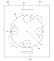
- FIG. 1 is a plan view showing a tool rotating device (PVD processing device) used in a non-limiting one-surface coating method of the present disclosure.
- FIG. 2 is a side view of the tool rotation device shown in FIG. 1 .
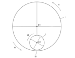
- FIG. 2 is a schematic diagram showing the positional relationship between a revolution table and a rotation table in a non-limiting one-side coating method according to the present disclosure.
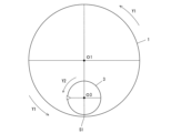
- FIG. 2 is a schematic diagram showing the positional relationship between a revolution table and a rotation table in a non-limiting one-side coating method according to the present disclosure.
- FIG. 2 is a schematic diagram showing the positional relationship between a revolution table and a rotation table in a non-limiting one-side coating method according to the present disclosure.
- FIG. 2 is a schematic diagram showing the positional relationship between a revolution table and a rotation table in a non-limiting one-side coating method according to the present disclosure.
- FIG. 1 is a plan view showing a tool rotating device (PVD processing device) used in
- FIG. 2 is a schematic diagram showing the positional relationship between a revolution table and a rotation table in a non-limiting one-side coating method according to the present disclosure.
- FIG. 2 is a schematic diagram showing the positional relationship between a revolution table and a rotation table in a non-limiting one-side coating method according to the present disclosure.
- FIG. 2 is a schematic diagram showing the positional relationship between a revolution table and a rotation table in a non-limiting one-side coating method according to the present disclosure.
- FIG. 2 is a schematic diagram showing the positional relationship between a revolution table and a rotation table in a non-limiting one-side coating method according to the present disclosure.
- FIG. 2 is a schematic diagram showing the positional relationship between a revolution table and a rotation table in a non-limiting one-side coating method according to the present disclosure.
- FIG. 2 is a schematic diagram showing the positional relationship between a revolution table and a rotation table in a non-limiting one-side coating method according to the present disclosure.
- FIG. 2 is a schematic diagram showing the positional relationship between a revolution table and a rotation table in a non-limiting one-side coating method according to the present disclosure.
- FIG. 2 is a schematic diagram showing the positional relationship between a revolution table and a rotation table in a non-limiting one-side coating method according to the present disclosure.
- FIG. 2 is a schematic diagram showing the positional relationship between a revolution table and a rotation table in a non-limiting one-side coating method according to the present disclosure.
- FIG. 2 is a schematic diagram showing the positional relationship between a revolution table and a rotation table in a non-limiting one-side coating method according to the present disclosure.
- the coating method may be a method of coating a coating layer on the surface of the tool 301 (see FIG. 2).
- the tool 301 coated with a coating layer on its surface may be called a coated tool.
- coating may also be called film formation.
- the coating method may also be called film formation method.
- the coating layer may also be called a coating.
- the coating layer may simply be called a film.
- the tool 301 to be coated may be plate-shaped.
- the tool 301 may be in the shape of a square plate.
- the shape of the tool 301 is not limited to a square plate.
- the top surface of the tool 301 may be triangular, pentagonal, hexagonal, or circular.
- the tool 301 may be a cutting tool.
- the tool 301 may also have a through hole. If the tool 301 is a cutting tool, the through hole may function as a portion to which a fixing screw or a clamp member is attached when the cutting tool is held in a holder.
- the tool 301 is not limited to a specific size.
- the length of one side of the upper surface may be set to about 3 to 20 mm.
- the height from the upper surface to the lower surface may be set to about 5 to 20 mm.
- the tool 301 is not limited to being plate-shaped.
- the tool 301 may be rod-shaped, etc.
- the material of the tool 301 may be, for example, a cemented carbide or a cermet.
- the composition of the cemented carbide may be, for example, WC-Co, WC-TiC-Co, and WC-TiC-TaC-Co.
- WC, TiC, and TaC may be hard particles, and Co may be a binder phase.
- the cermet may be a sintered composite material in which a ceramic component is combined with a metal.
- An example of a cermet is a titanium compound mainly composed of TiC or TiN.
- the number of tools 301 to be coated may be, for example, about 5 to 80.
- the number of tools 301 shown in the example may be the number per support pillar, which will be described later.
- the composition of the coating layer applied to the surface of the tool 301 may include, for example, titanium carbide (TiC), titanium nitride (TiN), titanium carbonitride (TiCN), and alumina (Al 2 O 3 ).
- the coating layer is not limited to a specific thickness.
- the average thickness of the coating layer may be set to about 0.1 to 10 ⁇ m.
- the thickness of the coating layer may be measured by cross-sectional observation using an electron microscope.
- the thickness may be measured at 10 or more measurement points at any position on the coating layer, and the average value may be calculated.
- electron microscopes include a scanning electron microscope (SEM) and a transmission electron microscope (TEM).
- the coating method may be a method in which, as in a non-limiting example shown in Figures 1 and 2, the tool 301 is rotated around a rotation axis O2 parallel to the revolution axis O1 while revolving the tool 301 around the revolution axis O1, and a coating layer is coated on the surface of the tool 301 by a PVD method.
- the PVD method include an ion plating method and a sputtering method.
- the coating method may use a revolution table 1 and a rotation table 3.
- the revolution table 1 may be a member that revolves the tool 301 around the revolution axis O1.
- the central axis of the revolution table 1 may coincide with the revolution axis O1.
- the revolution table 1 is rotatable around the revolution axis O1.
- the arrow Y1 in FIG. 1 etc. may indicate the direction of rotation of the revolution table 1.
- the revolution table 1 may rotate in the opposite direction to the arrow Y1.
- a motor and gears may be used to rotate the revolution table 1.
- the driving force of the motor may be transmitted to the revolution table 1 via gears to rotate the revolution table 1. This is the same for other rotatable members such as the rotation table 3 described below.
- the revolution table 1 may be disk-shaped.
- the outer diameter of the revolution table 1 may be set to, for example, about 300 to 600 mm.
- the rotating table 3 may be a member that rotates the tool 301 on the revolution table 1 around a rotation axis O2 that is parallel to the revolution axis O1.
- the rotating table 3 is also rotatable around a central axis O3 of the rotating table 3.
- the central axis O3 of the rotating table 3 may be parallel to the revolution axis O1.
- the arrow Y2 in FIG. 1 etc. may indicate the rotation direction of the rotating table 3.
- the rotating table 3 may rotate in the opposite direction to the arrow Y2.
- the rotating table 3 may have a plate-shaped main body 5 and a top plate 7 facing the main body 5 at a distance in the direction along the central axis O3, as shown in a non-limiting example in FIG. 2.
- the main body 5 and the top plate 7 may be disk-shaped with an outer diameter smaller than that of the revolution table 1.
- the outer diameter of the main body 5 and the top plate 7 may be set to, for example, about 100 to 150 mm.
- the multiple rotation tables 3 may be located on the outer periphery of the revolution axis O1 on the upper surface 9 of the revolution table 1, as in the non-limiting example shown in FIG. 1.
- the multiple rotation tables 3 may be located at equal intervals in the circumferential direction of the revolution axis O1.
- the number of rotation tables 3 may be, for example, about 2 to 10.
- the rotation speed of the revolution table 1 may be a (rpm), and the rotation speed of the rotation table 3 may be b (rpm).
- the rotation speed may also be referred to as the number of rotations.
- the ratio b/a of a and b is not an integer, in other words, if the values of a and b are not an integer ratio, the uniformity of the coated film is likely to be improved. This is because when the tool 301 approaches the target in the PVD processing device described below due to the rotation of the revolution table 1, it is easy to avoid the same surface of the tool 301 facing the target.
- ⁇ may be an irrational number. Note that since it is practically difficult to set ⁇ to an irrational number in the strict sense in the coating process, ⁇ may be a number with two or more decimal places.
- the ratio b/a of a and b may be 0 ⁇ b/a ⁇ 1, but may also be 1 ⁇ b/a. Since the driving force required to rotate the revolution table 1 is greater than the driving force required to rotate the rotation table 3, it is easier to reduce the power consumption required for the coating process when 1 ⁇ b/a. From the viewpoint of improving the uniformity of the film coated during one rotation of the revolution table 1, it is desirable for b to be greater than twice a, that is, 2 ⁇ b/a. Therefore, when the ratio b/a of a and b is greater than 2 and is not an integer, excellent coatability is achieved.
- the uniformity of the coated film may be evaluated as follows. First, the thickness of the film coated on the top surface of the tool 301 is measured. The location for measuring the film thickness is set according to the shape of the top surface of the tool 301 as follows. If the top surface of the tool 301 is polygonal, at least three points near the vertices are measured. If the top surface of the tool 301 is circular, a point near a tangent point on a circumference obtained by dividing the circumference into thirds is measured. The nearby point may be a point 0.5 mm away from the vertex or tangent point. Next, the maximum value of the measured film thickness is set as X, the minimum value as Y, and the average value as Z. Then, the film may be evaluated as uniform when the value calculated by applying X, Y, and Z to the formula: [[(X-Y)/Z]/2] x 100 does not exceed 25%.
- a and b may be such that b ⁇ 5a. In this case, the uniformity of the coated film is likely to be improved.
- a may be set to 0.5 to 10 rpm, and b may be set to 8 to 20 rpm.
- the settings of a and b may be performed by adjusting the gear ratio, etc.
- a reference position S1 may be set for the position of the revolution table 1 and the rotation table 3 at the start of rotation.
- the deviation of the rotation table 3 from the reference position S1 when the revolution table 1 rotates once may be set to ⁇ °.
- ⁇ ° may be 10° ⁇ 350°.
- the uniformity of the coated film is likely to be improved. Specifically, it is likely to be avoided that the thickness of the film coated on the outward facing surface of the tool 301 at the reference position S1 is excessively thick compared to other parts.
- the reference position S1 may be a position facing a target in a PVD processing apparatus, which will be described later.
- the coating method may use a tool rotation device 101.
- the tool rotation device 101 may include a revolution table 1 and a rotation table 3, as shown in a non-limiting example in Figures 1 and 2.
- the rotating table 3 can rotate around the central axis O3 of the rotating table 3.
- the rotating table 3 can also have a support 11, as in the non-limiting example shown in FIG. 2.
- the support 11 can hold the tool 301. If the tool 301 has the above-mentioned through hole, the support 11 can be inserted into the through hole to hold the tool 301 on the support 11. If the tool 301 is rod-shaped, the tool 301 can be held on the support 11 using a jig or the like.
- the support pillar 11 may be located between the main body 5 and the top plate 7.
- the support pillar 11 may also be cylindrical.
- the diameter of the support pillar 11 may be set to about 1 to 10 mm.
- the length of the support pillar 11 may be set to about 200 to 700 mm.
- the turntable 3 may have multiple support pillars 11.
- the multiple support pillars 11 may be positioned at equal intervals in the circumferential direction of the central axis O3.
- the rotation axis O2 may be located on the outer periphery side of the rotation table 3 relative to the central axis O3.
- the support pillar 11 may extend along the rotation axis O2.
- the support pillar 11 is rotatable around the rotation axis O2.
- the main body 5 and the top plate 7 may have a through hole through which the end of the support 11 can be inserted, or a recess into which the end of the support 11 can be inserted, and the end of the support 11 may be positioned in this through hole or recess to make the support 11 rotatable.
- the driving force from a motor may be transmitted to the support 11 via a gear to rotate the support 11.
- the driving force may be transmitted to the support 11 by a gear and a kicker to rotate the support 11.
- the arrow Y3 in FIG. 2 may indicate the direction of rotation of the support 11.
- the support 11 may rotate in the opposite direction to the arrow Y3.
- the number of pillars 11, n1, may be set to 4 to 36. If there are multiple rotating tables 3, n1 may be the number of pillars 11 on one rotating table 3.
- the coating time may be t (minutes).
- the value calculated by substituting a and t into the formula: a x t may be an integer multiple of the value calculated by substituting ⁇ ° into the formula: 360°/ ⁇ °.
- t may be set to 4 to 240 minutes.
- the integer multiple does not have to be an integer multiple in the strict sense.
- the integer multiple may be an approximate integer multiple. If the value calculated by applying ⁇ ° to the formula: 360°/ ⁇ ° is within the range of ⁇ 0.2 of the integer N1, it may be considered to be an integer multiple.
- the revolution table 1 and the rotation table 3 may start rotating from the non-limiting example state shown in Figure 3. Then, the revolution table 1 and the rotation table 3 may move from the state shown in Figure 3 to the states shown in Figures 4 to 15 in sequence.
- the non-limiting example shown in FIG. 4 may show a state in which the revolution table 1 has completed one rotation and returned to its original position (the position shown in FIG. 3). At this time, the rotation table 3 may rotate m1 times. m1 may be set to 4 to 60 rotations.
- the rotating table 3 may be at a position 30° ahead of its original position. In other words, when the revolution table 1 rotates 360°, the rotating table 3 may rotate (360° ⁇ m1)+30°.
- the non-limiting example shown in FIG. 5 may show a state in which the revolution table 1 has made one further rotation and returned to its original position (a total of two rotations). At this time, the rotation table 3 may make another m1 rotation.
- the rotation table 3 may also be in a position 60° forward from its original position. It may also be in a position 30° forward from the position of the rotation table 3 when the revolution table 1 made one rotation (the position shown in FIG. 4).
- the non-limiting example shown in FIG. 6 may show a state in which the revolution table 1 has made one more rotation and returned to its original position (a total of three rotations). At this time, the rotation table 3 may make an additional m1 rotation.
- the rotation table 3 may also be in a position 90° forward from its original position. It may also be in a position 30° forward from the position of the rotation table 3 when the revolution table 1 has made two rotations (the position shown in FIG. 5).
- the non-limiting example shown in FIG. 7 may show a state in which the revolution table 1 has made one further rotation and returned to its original position (a total of four rotations). At this time, the rotation table 3 may make another m1 rotation.
- the rotation table 3 may also be in a position 120° forward from its original position. It may also be in a position 30° forward from the position of the rotation table 3 when the revolution table 1 has made three rotations (the position shown in FIG. 6).
- the non-limiting example shown in FIG. 8 may show a state in which the revolution table 1 has made one more rotation and returned to its original position (a total of five rotations). At this time, the rotation table 3 may make an additional m1 rotation.
- the rotation table 3 may also be in a position 150° forward from its original position. It may also be in a position 30° forward from the position of the rotation table 3 when the revolution table 1 has made four rotations (the position shown in FIG. 7).
- the non-limiting example shown in FIG. 9 may show a state in which the revolution table 1 has made one more rotation and returned to its original position (a total of six rotations). At this time, the rotation table 3 may make an additional m1 rotation.
- the rotation table 3 may also be in a position 180° forward from its original position. It may also be in a position 30° forward from the position of the rotation table 3 when the revolution table 1 has made five rotations (the position shown in FIG. 8).
- the non-limiting example shown in FIG. 10 may show a state in which the revolution table 1 has made one further rotation and returned to its original position (a total of seven rotations). At this time, the rotation table 3 may make another m1 rotation.
- the rotation table 3 may also be in a position 210° forward from its original position. It may also be in a position 30° forward from the position of the rotation table 3 when the revolution table 1 has made six rotations (the position shown in FIG. 9).
- the non-limiting example shown in FIG. 11 may show a state in which the revolution table 1 has made one more rotation and returned to its original position (a total of eight rotations). At this time, the rotation table 3 may make an additional m1 rotation.
- the rotation table 3 may also be in a position 240° forward from its original position. It may also be in a position 30° forward from the position of the rotation table 3 when the revolution table 1 has made seven rotations (the position shown in FIG. 10).
- the non-limiting example shown in FIG. 12 may show a state in which the revolution table 1 has made one more rotation and returned to its original position (a total of nine rotations). At this time, the rotation table 3 may make an additional m1 rotation.
- the rotation table 3 may also be in a position 270° forward from its original position. It may also be in a position 30° forward from the position of the rotation table 3 when the revolution table 1 has made eight rotations (the position shown in FIG. 11).
- the non-limiting example shown in FIG. 13 may show a state in which the revolution table 1 has made one further rotation and returned to its original position (a total of 10 rotations). At this time, the rotation table 3 may make another m1 rotation.
- the rotation table 3 may also be in a position 300° ahead of its original position. It may also be in a position 30° ahead of the position of the rotation table 3 when the revolution table 1 has made nine rotations (the position shown in FIG. 12).
- the non-limiting example shown in FIG. 14 may show a state in which the revolution table 1 has made one more rotation and returned to its original position (a total of 11 rotations). At this time, the rotation table 3 may make an additional m1 rotation. The rotation table 3 may also be in a position 330° forward from its original position. The rotation table 3 may be in a position 30° forward from the position of the rotation table 3 when the revolution table 1 has made 10 rotations (the position shown in FIG. 13).
- the non-limiting example shown in FIG. 15 may show a state in which the revolution table 1 has made one more rotation and returned to its original position (a total of 12 rotations). At this time, the rotation table 3 may make an additional m1 rotation.
- the rotation table 3 may also be in a position 360° forward from its original position. It may also be in a position 30° forward from the position of the rotation table 3 when the revolution table 1 has made 11 rotations (the position shown in FIG. 14).
- the non-limiting example shown in FIG. 15 may show the positional relationship between the revolution table 1 and the rotation table 3 at the end of coating. If the value calculated by applying a and t to the formula: a ⁇ t is an integer multiple of the value calculated by applying ⁇ ° to the formula: 360°/ ⁇ °, the revolution table 1 and the rotation table 3 are likely to be in the state shown in FIG. 15 at the end of coating. If the revolution table 1 and the rotation table 3 are in the state shown in FIG. 15 at the end of coating, the uniformity of the coated film is likely to be improved. Note that the state shown in FIG. 15 may be repeated several times during coating.
- the rotation speed of the support 11 may be c (rpm).
- b and c may be b>c. In this case, the uniformity of the coated film is likely to be improved.
- c may be set to 0.5 to 4 rpm. Also, c may be set by adjusting the gear ratio, etc.
- the coating method may use a PVD processing device 201 that performs coating using the PVD method.
- the PVD processing device 201 may include a tool rotation device 101, a target 203, and a vacuum chamber 205, as shown in FIG. 1 as a non-limiting example.
- the target 203 may be located outside the revolution table 1.
- the target 203 may also be located radially outside the revolution table 1.
- the target 203 may be located on the inner wall surface of the vacuum chamber 205.
- the target 203 may be formed from a film-forming material that is the raw material for the coating layer.
- the target 203 may also be called an evaporation source or a deposition source.
- the target 203 may be in the form of a plate.
- the multiple targets 203 may be formed from different types of deposition materials, or may be formed from the same type of deposition material.
- the multiple targets 203 may be positioned at intervals in the direction along the revolution axis O1.
- the multiple targets 203 may be positioned at intervals along the circumferential direction of the revolution table 1. For example, when there are two targets 203, the two targets 203 may be positioned so as to face each other with the revolution table 1 in between. When there are multiple targets 203, the number of targets 203 may be, for example, about 2 to 16.
- the vacuum chamber 205 may house the tool rotation device 101 and the target 203 inside.
- the inside of the vacuum chamber 205 can be depressurized.
- an exhaust pipe may be connected to the vacuum chamber 205, and a vacuum pump or the like may be connected to the exhaust pipe, and the inside may be evacuated to a vacuum or extremely low pressure.
- a gas supply pipe may be connected to the vacuum chamber 205, and an inert gas or a reactive gas or the like may be supplied to the inside of the vacuum chamber 205.
- the surface of the tool was coated with a coating layer under the following coating conditions: PVD method: Arc ion plating method
- Tool shape Square plate shape
- Number of tools to be coated 36 (number per support)
- Coating layer composition TiN Average thickness of coating layer: 2.5 ⁇ m
- the uniformity of the coated film was good. Specifically, the value calculated from the above formula: [[(X-Y)/Z]/2] x 100 did not exceed 25%. Therefore, it can be said that the above coating method has excellent coatability.
- revolution table 3 rotation table 5: main body 7: top plate 9: upper surface 11: support 101: tool rotation device 201: PVD processing device 203: target 205: vacuum chamber 301: tool O1: revolution axis O2: rotation axis O3: central axis S1: reference position
Landscapes
- Chemical & Material Sciences (AREA)
- Chemical Kinetics & Catalysis (AREA)
- Engineering & Computer Science (AREA)
- Materials Engineering (AREA)
- Mechanical Engineering (AREA)
- Metallurgy (AREA)
- Organic Chemistry (AREA)
- Physical Vapour Deposition (AREA)
Priority Applications (3)
| Application Number | Priority Date | Filing Date | Title |
|---|---|---|---|
| PCT/JP2023/013912 WO2024209529A1 (ja) | 2023-04-04 | 2023-04-04 | コーティング方法 |
| JP2025512235A JPWO2024209529A1 (https=) | 2023-04-04 | 2023-04-04 | |
| CN202380096555.8A CN120882896A (zh) | 2023-04-04 | 2023-04-04 | 涂覆方法 |
Applications Claiming Priority (1)
| Application Number | Priority Date | Filing Date | Title |
|---|---|---|---|
| PCT/JP2023/013912 WO2024209529A1 (ja) | 2023-04-04 | 2023-04-04 | コーティング方法 |
Publications (1)
| Publication Number | Publication Date |
|---|---|
| WO2024209529A1 true WO2024209529A1 (ja) | 2024-10-10 |
Family
ID=92971565
Family Applications (1)
| Application Number | Title | Priority Date | Filing Date |
|---|---|---|---|
| PCT/JP2023/013912 Ceased WO2024209529A1 (ja) | 2023-04-04 | 2023-04-04 | コーティング方法 |
Country Status (3)
| Country | Link |
|---|---|
| JP (1) | JPWO2024209529A1 (https=) |
| CN (1) | CN120882896A (https=) |
| WO (1) | WO2024209529A1 (https=) |
Citations (3)
| Publication number | Priority date | Publication date | Assignee | Title |
|---|---|---|---|---|
| JPH02210636A (ja) * | 1988-10-19 | 1990-08-22 | Fuji Photo Film Co Ltd | 光磁気記録媒体の製造方法及び製造装置 |
| JP2002532626A (ja) * | 1998-12-15 | 2002-10-02 | ユナキス・バルツェルス・アクチェンゲゼルシャフト | 遊星システム工作物キャリヤおよび工作物の表面処理方法 |
| WO2020183827A1 (ja) * | 2019-03-12 | 2020-09-17 | 株式会社アルバック | 成膜方法 |
-
2023
- 2023-04-04 JP JP2025512235A patent/JPWO2024209529A1/ja active Pending
- 2023-04-04 WO PCT/JP2023/013912 patent/WO2024209529A1/ja not_active Ceased
- 2023-04-04 CN CN202380096555.8A patent/CN120882896A/zh active Pending
Patent Citations (3)
| Publication number | Priority date | Publication date | Assignee | Title |
|---|---|---|---|---|
| JPH02210636A (ja) * | 1988-10-19 | 1990-08-22 | Fuji Photo Film Co Ltd | 光磁気記録媒体の製造方法及び製造装置 |
| JP2002532626A (ja) * | 1998-12-15 | 2002-10-02 | ユナキス・バルツェルス・アクチェンゲゼルシャフト | 遊星システム工作物キャリヤおよび工作物の表面処理方法 |
| WO2020183827A1 (ja) * | 2019-03-12 | 2020-09-17 | 株式会社アルバック | 成膜方法 |
Also Published As
| Publication number | Publication date |
|---|---|
| JPWO2024209529A1 (https=) | 2024-10-10 |
| CN120882896A (zh) | 2025-10-31 |
Similar Documents
| Publication | Publication Date | Title |
|---|---|---|
| CN105051247B (zh) | Pvd处理装置以及pvd处理方法 | |
| WO2011135810A1 (ja) | 成膜装置 | |
| CN102245799B (zh) | 用于基片组件的表面处理和/或表面涂敷的设备 | |
| US20170183769A1 (en) | Film formation apparatus and film-formed workpiece manufacturing method | |
| JP2009041040A (ja) | 真空蒸着方法および真空蒸着装置 | |
| KR20130060544A (ko) | 나노멀티레이어 코팅층 형성방법 및 형성장치 | |
| TWI386504B (zh) | Film forming apparatus and film forming method | |
| KR100797447B1 (ko) | 마그네트론 스퍼터링 장치, 원통형 캐소드 및 기재상의다성분 필름 코팅 방법 | |
| WO2014076947A1 (ja) | 成膜装置 | |
| KR20190136771A (ko) | 연동 회전하는 회전기를 가지는 증착장치 | |
| WO2024209529A1 (ja) | コーティング方法 | |
| WO2024194994A1 (ja) | ワーク回転装置、pvd処理装置および被覆工具の製造方法 | |
| CN110408904A (zh) | 一种溅射成膜装置 | |
| JP7756002B2 (ja) | Pvdプロセスで使用される円筒状の伸長基材用の固定具 | |
| WO2024194986A1 (ja) | 治具、工具回転装置、pvd処理装置および被覆工具の製造方法 | |
| WO2024194995A1 (ja) | ワーク回転装置、pvd処理装置および被覆工具の製造方法 | |
| JP7850396B2 (ja) | Iad成膜装置 | |
| WO2025004125A1 (ja) | 成膜方法 | |
| CN214496456U (zh) | 一种双束激发式金属-气体离子化设备 | |
| KR101926881B1 (ko) | 나노멀티레이어 코팅층, 그 형성방법 및 형성장치 | |
| JP2005232554A (ja) | スパッタ装置 | |
| CN221645054U (zh) | 一种样品位置转换组件 | |
| CN218507891U (zh) | 用于x射线管液态金属轴承的镀膜系统及旋转装置 | |
| JP7850815B2 (ja) | 被覆工具および切削工具 | |
| JP2017036466A (ja) | スパッタ装置及び成膜方法 |
Legal Events
| Date | Code | Title | Description |
|---|---|---|---|
| 121 | Ep: the epo has been informed by wipo that ep was designated in this application |
Ref document number: 23931941 Country of ref document: EP Kind code of ref document: A1 |
|
| ENP | Entry into the national phase |
Ref document number: 2025512235 Country of ref document: JP Kind code of ref document: A |
|
| WWE | Wipo information: entry into national phase |
Ref document number: 2025512235 Country of ref document: JP |
|
| WWE | Wipo information: entry into national phase |
Ref document number: 202380096555.8 Country of ref document: CN |
|
| WWP | Wipo information: published in national office |
Ref document number: 202380096555.8 Country of ref document: CN |
|
| NENP | Non-entry into the national phase |
Ref country code: DE |
|
| 122 | Ep: pct application non-entry in european phase |
Ref document number: 23931941 Country of ref document: EP Kind code of ref document: A1 |