WO2024204617A1 - 作業機 - Google Patents
作業機 Download PDFInfo
- Publication number
- WO2024204617A1 WO2024204617A1 PCT/JP2024/012841 JP2024012841W WO2024204617A1 WO 2024204617 A1 WO2024204617 A1 WO 2024204617A1 JP 2024012841 W JP2024012841 W JP 2024012841W WO 2024204617 A1 WO2024204617 A1 WO 2024204617A1
- Authority
- WO
- WIPO (PCT)
- Prior art keywords
- connection
- coils
- stator
- phase
- motor
- Prior art date
- Legal status (The legal status is an assumption and is not a legal conclusion. Google has not performed a legal analysis and makes no representation as to the accuracy of the status listed.)
- Ceased
Links
Images




Classifications
-
- B—PERFORMING OPERATIONS; TRANSPORTING
- B25—HAND TOOLS; PORTABLE POWER-DRIVEN TOOLS; MANIPULATORS
- B25F—COMBINATION OR MULTI-PURPOSE TOOLS NOT OTHERWISE PROVIDED FOR; DETAILS OR COMPONENTS OF PORTABLE POWER-DRIVEN TOOLS NOT PARTICULARLY RELATED TO THE OPERATIONS PERFORMED AND NOT OTHERWISE PROVIDED FOR
- B25F5/00—Details or components of portable power-driven tools not particularly related to the operations performed and not otherwise provided for
-
- H—ELECTRICITY
- H02—GENERATION; CONVERSION OR DISTRIBUTION OF ELECTRIC POWER
- H02K—DYNAMO-ELECTRIC MACHINES
- H02K3/00—Details of windings
- H02K3/04—Windings characterised by the conductor shape, form or construction, e.g. with bar conductors
- H02K3/18—Windings for salient poles
Definitions
- the present invention relates to a work machine.
- Patent Document 1 discloses an electric tool as a work machine in which the motor winding connection method can be switched between series connection and parallel connection depending on the type of power source (power source voltage) connected. Patent Document 1 also discloses that a board equipped with a relay for switching the connection method is attached to the end of the motor (the end of the stator).
- connections between the windings and the relays for switching connections are arranged in a centralized location, the centralized area and the surrounding structure may become larger, which may result in the housing becoming larger.
- the object of the present invention is to provide a work machine that can prevent the components or housing from becoming too large.
- One aspect of the present invention is a work machine.
- This work machine has a motor with multiple coils, an inverter circuit that supplies current to the multiple coils, and a connection circuit that is connected to the inverter circuit and connects the multiple coils.
- the connection circuit has a first connection connection part that is conductive only when the multiple coils are connected to a first connection, a second connection connection part that is conductive only when the multiple coils are connected to a second connection, and a common connection connection part that connects the multiple coils and is conductive in both the first connection and the second connection, and one of the common connection connection part, the first connection connection part, and the second connection connection part is provided on a substrate, and at least one of the other two is provided outside the substrate.
- the present invention may be expressed as an "electrical work machine", “electrical tool”, “electrical equipment”, etc., and such expressions are also valid aspects of the present invention.
- the present invention provides a work machine that can prevent components and housings from becoming too large.
- FIG. 1 is a left side view, with a portion in cross section, of a work machine 1 according to a first embodiment of the present invention
- 2A is a cross-sectional view taken along the line A-A in FIG. 1.
- FIG. 2B is an enlarged view of part B in FIG.
- FIG. 2 is a perspective view of a motor 30 and its surrounding configuration in the work machine 1.
- FIG. 4 is a top view of the motor 30 and its peripheral configuration.
- FIG. 2 is a top cross-sectional view of the motor 30 and its surrounding configuration.
- FIG. 4 is a view of the stator board 27 of the work machine 1 as viewed from the left.
- FIG. 2 is a circuit block diagram of the work machine 1.
- 8A is a circuit diagram of the motor connection circuit 46 in Fig. 7.
- FIG. 8B is a circuit diagram showing the motor connection circuit 46 in Fig. 7 divided into a stator 45 side and a stator board 27 side.
- FIG. 4 is an explanatory diagram of the winding process of the stator 45. Graph showing the change over time in the temperature of the switching element (FET) of the inverter circuit 47, the temperature of the relays RY1 to RY3 (delta connection relays), and the actual air temperature when the stator coil 37 is connected in delta connection and the work machine 1 is continuously operated under no load.
- FET switching element
- FIG. 1 Graph showing the change over time in the temperature of the switching element (FET) of the inverter circuit 47, the temperature of the relays RY1 to RY3 (delta connection relays), and the actual measured temperature of the air temperature when the stator coil 37 is connected in delta connection and high-load work is intermittently and repeatedly performed on the work machine 1.
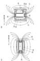
- 2A is a diagram showing the magnetic field lines generated by the relay coil 56 of the relay 28 when the iron core 55 of the relay 28 is perpendicular to the surface of the stator board 27, and the relative arrangement of the relay 28 and the Hall IC 29 for rotation detection, and FIG.
- FIG. 2B is a diagram showing the magnetic field lines generated by the relay coil 56 of the relay 28 when the iron core 55 of the relay 28 is parallel to the surface of the stator board 27, and the relative arrangement of the relay 28 and the Hall IC 29 for rotation detection
- 13A is a circuit diagram of a motor connection circuit in a work machine according to a second embodiment of the present invention
- FIG. 13B is a circuit diagram showing the motor connection circuit in FIG. 13A divided into a stator side and a stator board side.
- 1A is a circuit diagram of a motor connection circuit in a work machine according to a third embodiment of the present invention
- FIG. 1B is a circuit diagram of a motor connection circuit in a work machine according to a fourth embodiment of the present invention.
- FIG. 13 is a diagram showing a modified example of the motor connection circuit 46 in the present invention, in which a circuit for connecting the same phases is provided on the stator board.
- FIG. 13 is a diagram showing a modified example of the motor connection circuit 46 according to the present invention, in which a relay is provided on the inverter board 23 on which the inverter circuit is mounted.
- Figs. 1 to 12 relate to a work machine 1 according to embodiment 1 of the present invention.
- Figs. 1 and 2(A) define the mutually orthogonal front-rear, up-down, and left-right directions of the work machine 1.
- the work machine 1 is a bench cutting machine (bench circular saw).
- the working machine 1 has a base 2, a turntable 3, and a fence 4.
- the base 2 and the turntable 3 form a base section.
- the base 2 is placed on a workbench or the like.
- the turntable 3 is embedded in the center of the base 2 and can rotate relative to the base 2 by a rotation axis parallel to the vertical direction.
- the upper surface of the turntable 3 serves as a placement surface (base surface) on which the workpiece, such as wood, is placed.
- the upper surfaces of the base 2 and the turntable 3 are approximately flush with each other.
- the fence 4 is provided on the upper surface of the base 2. Stable cutting work is possible by abutting the workpiece against the fence 4.
- the work machine 1 has a holder 5.
- the holder 5 is connected to the rear end of the turntable 3 via a tilt shaft 6 and rises upward from the rear end of the turntable 3.
- the tilt shaft 6 is a shaft that is approximately parallel to the top surface of the turntable 3 and parallel to the side of the cutting blade 20.
- the axis of the tilt shaft 6 and the top surface of the turntable 3 are at approximately the same position in the vertical direction.
- the holder 5 can be tilted at a predetermined angle, for example, within a range of 45 degrees, to at least one of the left and right sides with respect to the turntable 3, centered on the tilt shaft 6.
- the tilted position of the holder 5 can be fixed and released by a clamp lever (not shown).
- the work machine 1 has a cutting unit 10.
- the cutting unit 10 is connected to the upper part of the holder 5 via a swing shaft 9 and extends in an upward and forward direction.
- the swing shaft 9 is a shaft that is approximately parallel to the rotation axis of the cutting blade 20.
- the cutting unit 10 can swing up and down around the swing shaft 9.
- a spring (not shown) that urges the cutting unit 10 upward relative to the holder 5 is provided around the swing shaft 9.
- Figure 1 shows the cutting unit 10 in the upper swing limit position.
- the cutting unit 10 is connected to the holder 5 via a slide rail (not shown) and can slide in the forward and backward directions relative to the holder 5 with the support of the slide rail.
- the cutting section 10 has a gear case (saw cover) 11 and a housing 12.
- the gear case 11 is made of a metal such as aluminum.
- the gear case 11 covers the upper outer periphery of the cutting blade 20.
- the housing 12 is, for example, a resin molded body, and is connected to the gear case 11 and located to the left of the gear case 11.
- the housing 12 has a handle housing 13 and a motor accommodating section 17.
- a trigger switch 14 (drive operation unit) is provided in the grip portion of the handle housing 13, which allows the operator to start and stop the motor 30.
- the rear of the motor housing portion 17 is a battery pack attachment portion 16, to which a battery pack 15 can be detachably attached.
- the work machine 1 runs on power from the battery pack 15.
- the motor housing portion 17 is formed by combining a motor housing 21 and a cover 22 with screws or the like.
- the motor housing 21 is an undivided cylinder whose central axis is parallel to the left-right direction.
- a cover 22 covers the opening on the left side of the motor housing 21.
- the motor housing 21 houses the motor 30 and the stator board 27.
- An air intake 18 (air window) is provided on the left side of the cover 22 to take in cooling air generated by the fan 50 described below.
- the motor shaft 31 extends perpendicular to the side of the cutting blade 20.
- the left part of the motor shaft 31 is supported by the left bearing 26.
- the left bearing 26 is held in the bearing holder 25 of the motor housing 21.
- the right part of the motor shaft 31 is supported by the right bearing 51.
- the rotor core 32 is generally cylindrical and is disposed around the motor shaft 31, rotating integrally with the motor shaft 31.
- the rotor magnet 33 is inserted and held in the rotor core 32.
- Four rotor magnets 33 are disposed around the rotor core 32, for example, at 90 degree intervals.
- a sensor magnet 42 is disposed on the left end surface of the rotor core 32.
- the magnetic pole faces of the sensor magnet 42 are the surface facing the rotor core 32 and the surface opposite it.
- the magnetic field generated by the sensor magnet 42 is detected by the Hall IC 29 described below.
- the rotor core 32, the rotor magnet 33, and the sensor magnet 42 constitute the rotor of the motor 30.
- the stator core 34 is held in the motor housing 21. As shown in FIG. 9, the stator core 34 has a yoke portion 62 and teeth portion 63.
- the yoke portion 62 is a tubular portion (cylindrical portion) that coaxially surrounds the rotor core 32.
- the teeth portion 63 protrudes radially inward from the yoke portion 62.
- Six teeth portions 63 are provided around the stator core 34, for example, at intervals of 60 degrees.
- a stator coil 37 is wound around each of the teeth portions 63. There are two stator coils 37 for each of the U-phase, V-phase, and W-phase, and in FIG. 8(A), (B), and FIG.
- the stator coils 37 are distinguished as U-phase stator coils U1 and U2, V-phase stator coils V1 and V2, and W-phase stator coils W1 and W2.
- the U phase corresponds to the first phase of the present invention, and the stator coils U1 and U2 that make up the U phase correspond to the first coil and second coil, respectively, of the present invention.
- the V phase corresponds to the second phase of the present invention, and the stator coils V1 and V2 that make up the V phase correspond to the third coil and fourth coil, respectively, of the present invention.
- the W phase corresponds to the third phase of the present invention, and the stator coils W1 and W2 that make up the W phase correspond to the fifth coil and sixth coil, respectively, of the present invention.
- the left insulator 35 is, for example, a resin molded body, and is provided to the left of the stator core 34 and is interposed between the stator coil 37 and the stator core 34. As shown in FIG. 4, the left insulator 35 guides a crossover wire 40 that connects the stator coils 37 of the same phase to the left of the stator core 34 in the circumferential direction of the motor shaft 31. The left insulator 35 holds a connect plate 41, which will be described later.
- the right insulator 36 is, for example, a resin molded body, and is provided to the right of the stator core 34 and is interposed between the stator coil 37 and the stator core 34.
- the stator core 34, the left insulator 35, the right insulator 36, the stator coil 37, and the connect plate 41 constitute the stator of the motor 30.
- the rotation of the motor 30, i.e., the rotation of the motor shaft 31, is transmitted forward by the winding transmission mechanism 52, and is then decelerated by the reduction mechanism 53 before being transmitted to the cutting blade 20.
- the cutting section 10 has a stator board 27 as a second board. As shown in FIG. 3, the stator board 27 is fixed to the left insulator 35 by, for example, three screws 38, and is supported in a position perpendicular to the motor shaft 31.
- the stator board 27 is approximately disc-shaped and has a smaller diameter than the stator of the motor 30.
- the five relays 28 are provided on the left side of the stator board 27.
- the five relays are distinguished as relays RY1 to RY5.
- the relay 28 is configured such that a magnetic field generated by passing a current through a relay coil 56 wound around an iron core 55 as a magnetic core attracts an iron piece 57 provided on a leaf spring 58 to the relay coil 56, and a movable contact 59 that operates integrally with the iron piece 57 comes into contact with a fixed contact 60 to turn on (conduct the current path).
- the elastic force of the leaf spring 58 causes the movable contact 59 to move away from the fixed contact 60, and the relay 28 turns off.
- the relay 28 is a through-hole mounting type. That is, the terminals of the relay 28 penetrate the through holes of the stator board 27 and are electrically connected to the stator board 27 by soldering or the like.
- the relay 28 has two terminals for passing current through the relay coil 56, and two terminals for connecting to the current path to be switched between conductive and cut-off, and is configured so that a total of four terminals are connected to the stator board 27. Note that the terminals are not shown in the figure.
- a Hall IC 29 is provided as a magnetic sensor on the right side of the stator board 27, i.e., the side of the stator board 27 opposite to the side on which the relay 28 is mounted.
- the Hall IC 29 is located inside the relay 28 in the radial direction of the motor shaft 31.
- FIG. 6 shows the left side of the stator board 27, and the Hall IC 29 provided on the right side of the stator board 27 is shown by a dashed line.
- Three Hall ICs 29 are provided at 60 degree intervals in the circumferential direction of the motor shaft 31.
- the Hall ICs 29 in this embodiment are configured to detect a magnetic field in a direction perpendicular to the stator board 27 (left-right direction). More specifically, the Hall ICs 29 in this embodiment are configured to output a voltage of a magnitude corresponding to the magnitude of the magnetic flux density in a direction perpendicular to the stator board 27.
- the electrical connection between the stator board 27 and the stator coil 37 is made by a metal connect plate 41 shown in Figures 3, 4, and 6.
- the connect plate 41 is, for example, a fusing terminal.
- the connect plate 41 is held by, for example, integral molding on the left insulator 35.
- the connect plate 41 may be configured as a separate body from the insulator and configured to be assembled to each other.
- Six connect plates 41 are provided, for example, at 60 degree intervals in the circumferential direction of the motor shaft 31.
- each connect plate 41 is shown in an open state before the stator coil 37 is wound or hooked and clamped.
- the jumper wire 40 that connects the stator coils 37 of the same phase and the end of the stator coil 37 are wound or hooked on each connect plate 41.
- Each connect plate 41 is electrically connected to the stator board 27 in a closed state as shown in Figure 4. 6 and 9, the six connect plates 41 are distinguished as connect plates 41U1, 41U2, 41V1, 41V2, 41W1, and 41W2 according to the phases of the corresponding stator coils 37.
- the stator board 27 is formed with conductive parts 27U1, 27U2, 27V1, 27V2, 27W1, and 27W2 that are electrically connected to the six connect plates 41, respectively.
- the conductive parts 27U1 to W2 are lands that are electrically connected to a conductive pattern (not shown) formed on the stator board 27.
- the conductive portions 27U1-W2 are electrical connection portions between the coil and the circuit board in the present invention, with the conductive portion 27U1 corresponding to the first connection portion, the conductive portion 27U2 corresponding to the second connection portion, the conductive portion 27V1 corresponding to the third connection portion, the conductive portion 27V2 corresponding to the fourth connection portion, the conductive portion 27W1 corresponding to the fifth connection portion, and the conductive portion 27W2 corresponding to the sixth connection portion.
- the connect plates 41U1-W2 are electrical connection portions between the coil and the circuit board in the present invention, with the connect plate 41U1 corresponding to the first connection portion, the connect plate 41U2 corresponding to the second connection portion, the connect plate 41V1 corresponding to the third connection portion, the connect plate 41V2 corresponding to the fourth connection portion, the connect plate 41W1 corresponding to the fifth connection portion, and the connect plate 41W2 corresponding to the sixth connection portion.
- the connect plate (connected part) functions to consolidate the connection points (in this embodiment, consolidate them into two points) when connecting both ends (four points in total) of the two coils that make up one phase to the circuit board.
- the cutting section 10 has an inverter board 23 as a first board and a board case 24 that houses and holds it.
- the board case 24 is located to the left of the bearing holding section 25.
- the inverter board 23 is held in the board case 24 to the left of the bearing holding section 25 in a position perpendicular to the motor shaft 31.
- the inverter board 23 and the board case 24 are located to the left of the motor housing 21 and have dimensions larger than the left opening of the motor housing 21 when viewed in the axial direction of the motor shaft 31.
- a switching element 49 for passing current to the stator coil 37 is provided on the left side of the inverter board 23.
- the switching element 49 corresponds to switching elements Q1 to Q6 such as FETs that constitute the inverter circuit 47 shown in Figure 7. Note that the switching element 49 is omitted from the illustration in Figure 3.
- the inverter board 23 is also equipped with circuit components such as a microcontroller that constitutes the calculation unit 80 shown in Figure 7, but these circuit components are omitted from the illustration in Figure 3.
- Switching elements Q1 to Q6 are examples of the first switch section.
- the inverter board 23 and the stator board 27 are electrically connected by the U-phase power line 43U, the V-phase power line 43V, and the W-phase power line 43W shown in FIG. 6.
- the U-phase power line 43U extends from the interconnection portion of the switching elements Q1 and Q4 shown in FIG. 7 on the inverter board 23 and is electrically connected to the stator board 27.
- the V-phase power line 43V extends from the interconnection portion of the switching elements Q2 and Q5 shown in FIG. 7 on the inverter board 23 and is electrically connected to the stator board 27.
- the W-phase power line 43W extends from the interconnection portion of the switching elements Q3 and Q6 shown in FIG.
- the U-phase power line 43U, the V-phase power line 43V, and the W-phase power line 43W are three power supply wires that extend from the U-phase, V-phase, and W-phase of the inverter circuit 47 to the motor connection circuit 46, as shown in FIG. 7.
- the cutting section 10 has a fan 50.
- the fan 50 is a centrifugal fan that is provided on the motor shaft 31 to the right of the stator core 34 and rotates together with the motor shaft 31.
- the flow of the cooling air generated by the fan 50 is shown by arrows in FIG. 2(A).
- the cooling air enters the cover 22 from the intake port 18 of the cover 22, cools the inverter board 23 and the switching element 49, then turns around to the right of the inverter board 23 to cool the stator board 27 and the relay 28, and further cools the motor 30 before being sucked into the fan 50. That is, the relay 28 is located downstream of the cooling air from the switching element 49.
- the notches 39 are configured so that at least a portion of them is in the same position as the relays 28 in the rotational direction of the motor shaft 31. In other words, the notches 39 are each disposed at a position corresponding to each relay 28. This makes it easier for the air passing through the notches 39 to hit the relays 28, allowing the relays 28 to be cooled appropriately. In this embodiment, a total of six notches 39 are provided.
- FIG. 7 is a circuit block diagram of the work machine 1.
- Figures 8(A) and (B) show a specific configuration of the motor connection circuit 46 in Figure 7.
- the motor connection circuit 46 includes U-phase stator coils U1 and U2, V-phase stator coils V1 and V2, W-phase stator coils W1 and W2, and relays RY1 to RY5.
- the relays RY1 to RY5 are connection switching units that switch the connections (hereinafter “stator coil connections") of the U-phase stator coils U1 and U2, the V-phase stator coils V1 and V2, and the W-phase stator coils W1 and W2 between a delta connection and a star connection (Y connection), and are examples of second switch units.
- the nominal heat resistance temperature (hereinafter “relay heat resistance temperature”) of the relays RY1 to RY5 is higher than the nominal heat resistance temperature (hereinafter “FET heat resistance temperature”) of the switching elements Q1 to Q6 (49) of the inverter circuit 47.
- Delta and star connections have different motor drive characteristics, and how they are applied in the control system is adjusted appropriately depending on the type of work and the type of work machine. For example, the motor may be driven with a delta connection when the load is low and with a star connection when the load is high.
- stator coil wiring When the stator coil wiring is a delta connection as the first connection, relays RY1 to RY3 are on (conductive state), and relays RY4 and RY5 are off (disconnected state). When the stator coil wiring is a star connection as the second connection, relays RY1 to RY3 are off (disconnected state), and relays RY4 and RY5 are on (conductive state).
- the jumper wire 40 functions as a circuit that connects coils of the same phase.
- the jumper wire 40 includes a first U-phase jumper wire 40U1 and a second U-phase jumper wire 40U2 that connect the U-phase coils together, a first V-phase jumper wire 40V1 and a second V-phase jumper wire 40V2 that connect the V-phase coils together, and a first W-phase jumper wire 40W1 and a second W-phase jumper wire 40W2 that connect the W-phase coils together.
- the jumper wire 40 and each connect plate 41 that connects the stator coils of the same phase are used as a current path (conductive state) in both the delta connection and the star connection.
- the jumper wire 40 and each connect plate 41 are examples of a common connection part.
- Relays RY1 to RY3 are relays for delta connection and are examples of the first connection part (first switching element) in the present invention.
- Relays RY4 and RY5 are relays for star connection and are examples of the second connection part (second switching element) in the present invention.
- the inverter circuit 47 converts the direct current output by the battery pack 15 into alternating current and supplies it to the motor connection circuit 46.
- the inverter circuit 47 includes switching elements Q1 to Q6, such as FETs and IGBTs, connected in a three-phase bridge. As described above, the switching elements Q1 to Q6 are examples of the first switch section.
- the resistor 48 is provided in the path of the current (hereinafter "motor current") flowing through the motor connection circuit 46.
- the current detection circuit 71 detects the motor current by the voltage drop at the resistor 48 and transmits it to the calculation unit 80.
- the voltage detection circuit 72 detects the output voltage of the battery pack 15 (hereinafter “battery voltage”) and transmits it to the calculation unit 80.
- the operation amount detection circuit 73 detects the on/off and operation amount of the trigger switch 14 and transmits it to the calculation unit 80.
- Thermistor 75 which serves as a temperature detection element, is provided on inverter board 23 and is positioned near one of switching elements Q1 to Q6, and outputs a signal corresponding to the temperature of that switching element (hereinafter "FET temperature"). Temperature detection circuit 74 detects the temperature of that switching element from the signal of thermistor 75 and sends it to calculation unit 80. Note that switching elements Q1 to Q6 are identical elements and have the same on-resistance and heat resistance temperature, and therefore experience substantially the same temperature changes. For this reason, it is sufficient to monitor the temperature change of one of switching elements Q1 to Q6.
- the rotor position detection circuit 76 detects the rotor rotation position of the motor 30 using the output signal (voltage) from the Hall IC 29 and sends it to the calculation unit 80.
- the rotation speed detection circuit 77 detects the rotation speed of the motor 30 (hereinafter "motor rotation speed") using the output signal from the rotor position detection circuit 76 and sends it to the calculation unit 80.
- the relay drive circuit 78 controls the on/off of the relay 28 (relays RY1 to RY5) according to the control of the calculation unit 80.
- the control signal output circuit 79 controls the on/off of the switching elements Q1 to Q6 of the inverter circuit 47 according to the control of the calculation unit 80.
- the calculation unit 80 is a control unit that controls the overall operation of the work machine 1.
- the calculation unit 80 monitors the motor current, battery voltage, on/off and operation amount of the trigger switch 14, FET temperature, rotor rotation position, and motor rotation speed, and controls the drive of the inverter circuit 47 (PWM control) via the control signal output circuit 79 in response to the operation of the trigger switch 14, thereby controlling the drive of the motor 30.
- the calculation unit 80 has an overload protection function (overcurrent protection function) that turns off all switching elements Q1 to Q6 and stops the power supply to the motor 30 when the motor current satisfies an overload protection activation condition (overcurrent protection activation condition) even if the trigger switch 14 is on.
- the overload protection activation condition is, for example, when the motor current is equal to or greater than the overload protection threshold (overcurrent protection threshold).
- the calculation unit 80 has a high temperature protection activation function that turns off all switching elements Q1 to Q6 and stops the power supply to the motor 30 when the FET temperature meets the high temperature protection activation condition, even if the trigger switch 14 is on.
- the high temperature protection activation condition is, for example, that the FET temperature is equal to or higher than a predetermined temperature (high temperature protection threshold).
- turning off all switching elements Q1 to Q6 to stop the power supply to the motor 30 is an example of controlling so that no current flows through the relays RY1 to RY5 (power supply to the relays RY1 to RY5 is cut off).
- the calculation unit 80 may turn off all relays RY1 to RY5 instead of or in addition to turning off all switching elements Q1 to Q6.
- the switching elements Q1 to Q6 as the first switch unit and the relays RY1 to RY5 as the second switch unit can each function as a means for cutting off the power supply to the motor 30.
- the FET temperature and the temperatures of the relays RY1 to RY5 rise. For this reason, it is possible to perform both control by monitoring the FET temperature so that the FET temperature does not exceed the FET heat resistance temperature, and control by monitoring the relay temperature so that the relay temperature does not exceed the relay heat resistance temperature.
- a thermistor 75 for monitoring the FET temperature and a thermistor for monitoring the relay temperature separately could result in increased costs, an increase in the size of the stator board 27 for mounting the thermistor, and ultimately an increase in the size of the work machine 1.
- the work machine 1 is therefore configured so that the FET temperature satisfies the high temperature protection activation condition before the relay temperature reaches the relay heat resistance temperature.
- the relay temperature is configured to be lower than the relay heat resistance temperature.
- the work machine 1 does not have a dedicated thermistor for monitoring the relay temperature, and the calculation unit 80 indirectly controls the relay temperature so that it does not exceed the relay heat resistance temperature by controlling the FET temperature so that it does not exceed the FET heat resistance temperature.
- the U-phase stator coils U1 and U2 are connected in parallel to each other, the V-phase stator coils V1 and V2 are connected in parallel to each other, and the W-phase stator coils W1 and W2 are connected in parallel to each other.
- These parallel connections are made by the first U-phase jumper wire 40U1, the second U-phase jumper wire 40U2, the first V-phase jumper wire 40V1, the second V-phase jumper wire 40V2, the first W-phase jumper wire 40W1, and the second W-phase jumper wire 40W2.
- Figure 8(B) shows that the parallel connection (parallel wiring) of the stator coils of each phase is completed on the stator 45 side, that is, it is established without relying on the conductive pattern (wiring pattern) of the stator board 27. This allows only six connect plates 41 to be used, and prevents the conductive pattern of the stator board 27 from becoming complicated or the stator board 27 from becoming large.
- the above winding process can be performed by an automatic winding machine (not shown).
- unnecessary portions of the wire portions indicated by two-dot chain lines in FIG. 9
- the portion spanning between connect plates 41U2 and W1 and the portion spanning between connect plates 41W1 and 41V2 are cut and removed. This completes the connection shown within the dashed lines of stator 45 in FIG. 8(B).
- the jumper wire 40 and each connect plate 41 that connect stator coils of the same phase are examples of common wiring connections. In the above winding process, there is no particular restriction as to which stator coil to start winding from.
- Figure 10 is a graph showing the time variation of the FET temperature, the temperature of relays RY1 to RY3 (delta connection relays) (hereinafter “delta relay temperature”), and the actual measured value of air temperature when the stator coil connection is delta connection and the work machine 1 is continuously operated in a no-load state.
- the FET temperature first rises temporarily due to the starting current of the motor 30. Both the FET temperature 69 and the delta relay temperature rose over time, but each plateaued at around 250 seconds. This is because the heat generated by the current flow and the cooling by the cooling air generated by the fan 50 are balanced and reach an equilibrium state.
- the FET temperature is configured to be higher than the delta relay temperature both when the temperature is rising and when it is in an equilibrium state.
- star relay temperature the relationship between the FET temperature and the temperature of relays RY4 and RY5 (hereinafter “star relay temperature" when the stator coil connection is star connection also shows a similar tendency to Figure 10.
- Figure 11 is a graph showing the time changes in the measured FET temperature, delta relay temperature, and air temperature when the stator coil is delta connected and high-load work is intermittently repeated with the work machine 1.
- the FET temperature increases during high-load work and decreases when work is stopped, and the time average value increases.
- the delta relay temperature increases, repeating small fluctuations at a temperature lower than the FET temperature.
- the relationship between the FET temperature and the star relay temperature when the stator coil is star connected also shows a similar tendency to Figure 11.
- the delta relay temperature is configured to be lower than the FET temperature.
- the relay heat resistance temperature is set higher than the FET heat resistance temperature, so that the FET temperature satisfies the high temperature protection activation condition before the relay temperature reaches the relay heat resistance temperature.
- the relay temperature is lower than the relay heat resistance temperature, and so temperature protection for the relay is activated.
- Figure 12(A) is a diagram showing the magnetic field lines of the magnetic field (hereinafter "relay magnetic field") generated by relay coil 56 (relay coil of this embodiment) in which the extension direction of iron core 55 of relay 28 is perpendicular to the surface of stator board 27, and the relative arrangement of relay 28 and Hall IC 29 for detecting rotation.
- the relative arrangement of relay 28 and Hall IC 29 shown in Figure 12(A) corresponds to the relative arrangement of relay 28 and Hall IC 29 shown in Figure 5.
- the Hall IC 29 detects a magnetic field perpendicular to the surface of the stator board 27 (hereinafter referred to as the "substrate perpendicular direction”), but does not detect a magnetic field parallel to the surface of the stator board 27 (hereinafter referred to as the "substrate parallel direction").
- the Hall IC 29 is configured to output a voltage in response to a magnetic field perpendicular to the board, and does not output a voltage in response to a magnetic field parallel to the board. For this reason, if the Hall IC 29 is placed in a position where the substrate perpendicular component of the relay magnetic field is large, there is a concern that the output signal of the Hall IC 29 may change unintentionally.
- the Hall IC 29 it is desirable to configure the Hall IC 29 so that the output signal (level) changes based only on the magnetic field of the sensor magnet 42, but the relay magnetic field emitted from the relay 28 located on the opposite side of the sensor magnet 42 changes the magnitude and direction of the magnetic field passing through the Hall IC 29, and there is a risk that the correct output signal corresponding to the position of the sensor magnet 42 will not be generated. In this case, there is a concern that a malfunction may occur.
- the Hall IC 29 is located outside the range of the iron core 55 when viewed in the axial direction of the iron core 55 (when viewed in the left-right direction). Also, the Hall IC 29 is located outside the range of the relay 28 when viewed in the vertical direction of the board (when viewed in the left-right direction). With this arrangement, when the iron core 55 is perpendicular to the surface of the stator board 27, the component of the relay magnetic field in the vertical direction of the board at the position of the Hall IC 29 is reduced, and unintended changes in the output signal of the Hall IC 29 are suppressed, thereby suppressing the risk of malfunction.
- the relative arrangement of the Hall IC 29 and the relay 28 may be such that the effect of the relay magnetic field on the output signal of the Hall IC 29 is substantially within a negligible range.
- the Hall IC 29 may be located outside the range of the iron core 55 when viewed in the axial direction of the iron core 55 (or outside the range of the relay coil 56) and within the range of the relay 28 when viewed in the vertical direction of the board.
- the relay 28 is a through-hole mounting type, and the terminals of the relay 28 protrude from the right surface (the surface facing the motor 30) of the stator board 27, where soldering is performed, resulting in a soldering area on the back side of the mounting surface of the relay 28.
- the Hall IC 29 is located in this area, problems may occur during the assembly process, and the need to fix the Hall IC 29 to the stator board 27 before fixing the relay 28 to the stator board 27 may lead to poor assembly.
- the Hall IC is located outside the presence range of the relay 28 (at a position where it does not overlap) when viewed vertically from the board, so such problems can be suppressed.
- FIG. 12B is a diagram showing the relative arrangement of the relay 28 and the Hall IC 29 and the magnetic field lines of the relay magnetic field when a relay 28 is used in which the iron core 55 is parallel to the surface of the stator board 27.
- at least a part of the Hall IC 29 is located within the range of the iron core 55 when viewed in the axial direction of the iron core 55.
- the Hall IC 29 is located within the range of the relay 28 (or within the range of the iron core 55 or the relay coil 56) when viewed from the board vertical direction.
- the Hall IC 29 is mounted on the side of the stator board 27 opposite the side on which the relay 28 is mounted.
- the board vertical component of the relay magnetic field at the position of the Hall IC 29 is reduced, suppressing unintended changes in the output signal of the Hall IC 29 and reducing the risk of malfunction. That is, when the direction of detection of the magnetic field is (almost) parallel to the direction of extension of the iron core 55, the relay 28 and the Hall IC 29 should be arranged so as not to overlap when viewed from the direction perpendicular to the board, and when the direction of detection of the magnetic field is (almost) perpendicular to the direction of extension of the iron core 55, the relay 28 and the Hall IC 29 should be arranged so as to overlap when viewed from the direction perpendicular to the board.
- the iron piece 57 is arranged sufficiently apart so that it is not operated by the magnetic force of the sensor magnet 42.
- the relay 28 (iron piece 57) is configured so that it is not turned on or off by a magnetic field generating element (sensor magnet 42) other than the relay coil 56, thereby suppressing malfunctions.
- the iron piece 57 is preferably located in the area opposite the sensor magnet 42 (left side of the center) inside the relay 28.
- the common wiring connection part crossover wire 40 and connect plate 41
- the first wiring connection part delta connection relay
- the second wiring connection part star connection relay
- the common wiring connection part is provided in the motor 30 (insulator 35)
- the first wiring connection part and the second wiring connection part are provided in the stator board 27.
- the coils of the same phase are configured to be connected in parallel when delta connected and when star connected. This parallel connection is achieved by the crossover wire 40 supported by the insulator 35.
- U-phase parallel connection the parallel connection of the U-phase stator coils U1 and U2 (hereinafter “U-phase parallel connection”), the parallel connection of the V-phase stator coils V1 and V2 (hereinafter “V-phase parallel connection”), and the parallel connection of the W-phase stator coils W1 and W2 (hereinafter “W-phase parallel connection”) are each completed on the stator 45 side, regardless of the conductive patterns of the stator board 27. That is, the coils of the same phase are connected in parallel before the stator board 27 is attached to the insulator 35.
- the connection between the stator coils in each parallel connection is configured by the conductive patterns of the stator board 27, the number of connect plates 41 (the number of electrical connection parts on the stator board 27) is reduced, and the complication of the conductive patterns of the stator board 27 or the increase in the conductive patterns through which a large current flows is suppressed. As a result, the stator board 27 becomes smaller, and an increase in cost and size of the product is suppressed.
- the interconnection between the U-phase parallel connection, V-phase parallel connection, and W-phase parallel connection i.e., the stator coil wiring
- the stator coil wiring is not fixed on the stator 45 side, so the stator coil wiring can be dynamically switched by relays RY1 to RY5 provided on the stator board 27.
- stator winding process is highly efficient, since all slots are wound at once and then unnecessary parts are cut off.
- connect plate 41 allows for electrical connection to the stator board 27 while connecting stator coils of the same phase, which prevents an increase in the number of parts and simplifies the structure.
- the switching element 49 is disposed upstream of the relay 28 in the flow of cooling air. This allows the cooling air that cools the relay 28 to cool the switching element 49, which generates a large amount of heat, before its temperature rises, and effectively suppresses the rise in the FET temperature.
- the motor housing 21 that holds the stator core 34 is a single (undivided) member. For this reason, compared to when the motor housing 21 has a two-part structure, for example, the coaxial precision of the bearing holder 25 of the motor housing 21 and the stator core 34 is improved, and the coaxial precision of the motor shaft 31 and the stator core 34 is also improved.
- the stator board 27 by making the stator board 27 smaller, it becomes easier to insert the stator 45, which is unitized with the stator board 27, into the cylindrical motor housing 21, which is a single member. In the case of an insertion configuration, it is necessary to secure space for insertion inside the motor housing 21, but by making the stator board 27 smaller, this space is reduced, and the motor housing 21 can also be made smaller.
- the work machine 1 is configured so that when the FET temperature exceeds a predetermined temperature (high temperature protection threshold), the relay temperature becomes lower than the relay heat resistance temperature.
- a predetermined temperature high temperature protection threshold
- the work machine 1 does not have a dedicated thermistor for monitoring the relay temperature
- the calculation unit 80 is configured to indirectly control the relay temperature so that it does not exceed the relay heat resistance temperature by controlling the FET temperature so that it does not exceed the FET heat resistance temperature. This makes it possible to suppress the increase in cost that would be caused by providing a dedicated thermistor for monitoring the relay temperature, the increase in size of the stator board 27 for mounting the thermistor, and ultimately the increase in size of the work machine 1.
- the Hall IC 29 is located outside the range of the iron core 55 when viewed in the axial direction of the iron core 55, and is also located outside the range of the relay 28 when viewed perpendicular to the board. This reduces the component of the relay magnetic field in the perpendicular direction to the board at the position of the Hall IC 29, suppressing unintended changes in the output signal of the Hall IC 29 and reducing the risk of malfunction.
- the Hall IC 29 is located outside the range of the iron core 55 when viewed in the axial direction (or outside the range of the relay coil 56) and within the range of the relay 28 when viewed perpendicular to the board, it is possible to arrange the Hall IC 29 relative to the iron core 55 so that the effect of the relay magnetic field on the output signal of the Hall IC 29 is substantially negligible.
- FIG. 13(A) is a circuit diagram of a motor connection circuit in a work machine according to embodiment 2 of the present invention.
- FIG. 13(B) is a circuit diagram showing the motor connection circuit in FIG. 13(A) divided into the stator side and the stator board side. The following mainly describes the differences from embodiment 1.
- the U-phase stator coils U1 and U2 are connected in series with each other, the V-phase stator coils V1 and V2 are connected in series with each other, and the W-phase stator coils W1 and W2 are connected in series with each other.
- the common connection section in this embodiment includes crossover wires 40U, 40V, and 40W for connecting coils of the same phase in series (for series connection). Therefore, the common connection section (crossover wire 40), the first connection section (delta connection relay), and the second connection section (star connection relay) are not provided in the same place, that is, they are arranged separately.
- This embodiment also achieves the same effects as embodiment 1.
- FIG. 14(A) is a circuit diagram of a motor wiring circuit in a work machine according to embodiment 3 of the present invention.
- the connection form of the different correlations is a delta connection
- relays RY11 to RY19 switch the connection form of the multiple stator coils of each phase between series connection and parallel connection.
- the U-phase stator coils U1 and U2 are connected in parallel to each other
- the V-phase stator coils V1 and V2 are connected in parallel to each other
- the W-phase stator coils W1 and W2 are connected in parallel to each other.
- Relays RY11 to RY16 are examples of a first wiring connection part (series connection part).
- the U-phase stator coils U1 and U2 are connected in series with each other
- the V-phase stator coils V1 and V2 are connected in series with each other
- the W-phase stator coils W1 and W2 are connected in series with each other.
- Relays RY17 to RY19 are examples of the second wiring connection part. That is, the relay in this embodiment is a wiring connection part (series-parallel switching connection part) that switches between series and parallel.
- the crossover wires and connect plates that connect the stator coils of different phases i.e., the U-phase stator coil U1 and the W-phase stator coil W2, the U-phase stator coil U2 and the V-phase stator coil V2, and the V-phase stator coil V1 and the W-phase stator coil W1, constitute a common wiring connection part, which are held by the insulator 35, and each relay is held by the stator board 27 or the inverter board 23.
- This embodiment also has the same effects as the first embodiment.
- FIG. 14(B) is a circuit diagram of a motor connection circuit in a work machine according to a fourth embodiment of the present invention.
- the connection form of the different correlations is a star connection, and relays RY21 to RY29 switch the connection form of the multiple stator coils of each phase between a series connection (first connection) and a parallel connection (second connection).
- the U-phase stator coils U1 and U2 are connected in parallel to each other, the V-phase stator coils V1 and V2 are connected in parallel to each other, and the W-phase stator coils W1 and W2 are connected in parallel to each other.
- the U-phase stator coils U1 and U2 are connected in series to each other, the V-phase stator coils V1 and V2 are connected in series to each other, and the W-phase stator coils W1 and W2 are connected in series to each other.
- the crossover wires and connect plates that connect the different phase stator coils i.e., the U-phase stator coil U2, the V-phase stator coil V2, and the W-phase stator coil W2, form a common wiring connection section, which are held by an insulator, and each relay is held by the stator board or inverter board 23.
- This embodiment also achieves the same effects as embodiment 1.
- Figure 15 shows an example in which the number of stator boards is increased to two, with a common wiring connection on one and first and second wiring connection on the other. Although this results in six wires to the insulator 35, this eliminates the need for a section in the insulator that holds the jumper wires, making it possible to miniaturize the motor 30.
- the common wiring connection part is provided on the insulator 35, while the first and second wiring connection parts are arranged on the inverter board 23 (main board).
- the motor 30 is controlled by vector control, which eliminates the need for a Hall IC. Therefore, a stator board is not required, and the number of parts can be reduced.
- the number of poles of the rotor and the number of slots of the stator do not limit the scope of the invention in any way and can be changed as desired to meet the required specifications.
- At least a part of the relay 28 for switching the wiring may be provided on the inverter board 23.
- the motor 30 may be driven without a sensor.
- the Hall IC 29 may be omitted.
- the relay 28 is configured so that it is not switched on and off due to the influence of the magnetism generated from an external magnetic source of the relay 28, for example, the rotor magnet 33.
- the working machine of the present invention is not limited to a bench cutter, and may be another type of cutting machine such as a portable circular saw, or may be another type of working machine such as a grinder.
- motor shaft 32... rotor core, 33... rotor magnet, 34... stator core, 35... left insulator, 36... right insulator, 37... stator coil, 38... screw, 39... notch, 40... jumper, 41, 41U1, 41U2, 41V1, 41V2, 41W1, 41W2...connect plate, 42...sensor magnet, 43U, 43V, 43W...power line, 44...through hole, 45...stator, 46...motor connection circuit, 47...inverter circuit, 48...resistor, 49...switching element, 50...fan, 51...right bearing, 52...winding transmission mechanism, 53...reduction mechanism, 55...iron core (magnetic core), 56...relay coil, 58...leaf spring, 59...movable contact, 60...fixed contact, 62...yoke portion, 63...teeth portion, 71...current detection circuit, 72...voltage detection circuit, 73...operation amount detection circuit, 74...temperature detection circuit, 75...thermistor (temperature detection element), 76...
Landscapes
- Engineering & Computer Science (AREA)
- Power Engineering (AREA)
- Mechanical Engineering (AREA)
Priority Applications (2)
| Application Number | Priority Date | Filing Date | Title |
|---|---|---|---|
| CN202480015718.XA CN120814153A (zh) | 2023-03-31 | 2024-03-28 | 作业机 |
| JP2025511207A JPWO2024204617A1 (https=) | 2023-03-31 | 2024-03-28 |
Applications Claiming Priority (2)
| Application Number | Priority Date | Filing Date | Title |
|---|---|---|---|
| JP2023-057497 | 2023-03-31 | ||
| JP2023057497 | 2023-03-31 |
Publications (1)
| Publication Number | Publication Date |
|---|---|
| WO2024204617A1 true WO2024204617A1 (ja) | 2024-10-03 |
Family
ID=92905891
Family Applications (1)
| Application Number | Title | Priority Date | Filing Date |
|---|---|---|---|
| PCT/JP2024/012841 Ceased WO2024204617A1 (ja) | 2023-03-31 | 2024-03-28 | 作業機 |
Country Status (3)
| Country | Link |
|---|---|
| JP (1) | JPWO2024204617A1 (https=) |
| CN (1) | CN120814153A (https=) |
| WO (1) | WO2024204617A1 (https=) |
Citations (6)
| Publication number | Priority date | Publication date | Assignee | Title |
|---|---|---|---|---|
| JPS4957305A (https=) * | 1972-06-20 | 1974-06-04 | ||
| JP2015133845A (ja) * | 2014-01-14 | 2015-07-23 | 日本電産株式会社 | モータ |
| JP2016010848A (ja) * | 2014-06-30 | 2016-01-21 | 日立工機株式会社 | 電動工具 |
| JP2021171869A (ja) * | 2020-04-23 | 2021-11-01 | 工機ホールディングス株式会社 | 動力工具 |
| JP2022052814A (ja) * | 2020-09-24 | 2022-04-05 | パナソニックIpマネジメント株式会社 | ブラシレスdcモータ |
| JP2023019272A (ja) * | 2021-07-29 | 2023-02-09 | 工機ホールディングス株式会社 | 作業機 |
-
2024
- 2024-03-28 JP JP2025511207A patent/JPWO2024204617A1/ja active Pending
- 2024-03-28 WO PCT/JP2024/012841 patent/WO2024204617A1/ja not_active Ceased
- 2024-03-28 CN CN202480015718.XA patent/CN120814153A/zh active Pending
Patent Citations (6)
| Publication number | Priority date | Publication date | Assignee | Title |
|---|---|---|---|---|
| JPS4957305A (https=) * | 1972-06-20 | 1974-06-04 | ||
| JP2015133845A (ja) * | 2014-01-14 | 2015-07-23 | 日本電産株式会社 | モータ |
| JP2016010848A (ja) * | 2014-06-30 | 2016-01-21 | 日立工機株式会社 | 電動工具 |
| JP2021171869A (ja) * | 2020-04-23 | 2021-11-01 | 工機ホールディングス株式会社 | 動力工具 |
| JP2022052814A (ja) * | 2020-09-24 | 2022-04-05 | パナソニックIpマネジメント株式会社 | ブラシレスdcモータ |
| JP2023019272A (ja) * | 2021-07-29 | 2023-02-09 | 工機ホールディングス株式会社 | 作業機 |
Also Published As
| Publication number | Publication date |
|---|---|
| CN120814153A (zh) | 2025-10-17 |
| JPWO2024204617A1 (https=) | 2024-10-03 |
Similar Documents
| Publication | Publication Date | Title |
|---|---|---|
| JP4974054B2 (ja) | 電動工具 | |
| JP7519827B2 (ja) | 電動作業機 | |
| CN104875166B (zh) | 电动工具 | |
| US12266986B2 (en) | Brushless motor and electrically-powered tool | |
| US12323011B2 (en) | Electric work machine | |
| JP2022185821A (ja) | 電動作業機 | |
| JP7475996B2 (ja) | 電動作業機 | |
| WO2021049124A1 (ja) | 電動作業機 | |
| WO2019151395A1 (ja) | ブラシレスモータ及びそれを用いた電気機器 | |
| JP7537510B2 (ja) | 作業機 | |
| JP7818154B2 (ja) | 作業機 | |
| JP2019047605A (ja) | 電気機器 | |
| JP7853587B2 (ja) | 作業機 | |
| WO2024204617A1 (ja) | 作業機 | |
| JP2024145234A (ja) | 作業機 | |
| JP6507773B2 (ja) | 手持ち電動工具 | |
| US20240266914A1 (en) | Electric work machine | |
| WO2024203180A1 (ja) | 作業機 | |
| JP2021158790A (ja) | ブラシレスモータ及び機器 | |
| WO2022209050A1 (ja) | 電気機器 | |
| JP7820201B2 (ja) | 電動作業機 | |
| JP2023137964A (ja) | 電動作業機 | |
| WO2023276354A1 (ja) | 作業機 |
Legal Events
| Date | Code | Title | Description |
|---|---|---|---|
| 121 | Ep: the epo has been informed by wipo that ep was designated in this application |
Ref document number: 24780716 Country of ref document: EP Kind code of ref document: A1 |
|
| WWE | Wipo information: entry into national phase |
Ref document number: 202480015718.X Country of ref document: CN |
|
| ENP | Entry into the national phase |
Ref document number: 2025511207 Country of ref document: JP Kind code of ref document: A |
|
| WWE | Wipo information: entry into national phase |
Ref document number: 2025511207 Country of ref document: JP |
|
| WWP | Wipo information: published in national office |
Ref document number: 202480015718.X Country of ref document: CN |
|
| NENP | Non-entry into the national phase |
Ref country code: DE |
|
| 122 | Ep: pct application non-entry in european phase |
Ref document number: 24780716 Country of ref document: EP Kind code of ref document: A1 |