WO2024204478A1 - 動作認証システム - Google Patents
動作認証システム Download PDFInfo
- Publication number
- WO2024204478A1 WO2024204478A1 PCT/JP2024/012523 JP2024012523W WO2024204478A1 WO 2024204478 A1 WO2024204478 A1 WO 2024204478A1 JP 2024012523 W JP2024012523 W JP 2024012523W WO 2024204478 A1 WO2024204478 A1 WO 2024204478A1
- Authority
- WO
- WIPO (PCT)
- Prior art keywords
- sensor
- wireless device
- time
- information
- phase
- Prior art date
- Legal status (The legal status is an assumption and is not a legal conclusion. Google has not performed a legal analysis and makes no representation as to the accuracy of the status listed.)
- Ceased
Links
Images





Classifications
-
- G—PHYSICS
- G06—COMPUTING OR CALCULATING; COUNTING
- G06T—IMAGE DATA PROCESSING OR GENERATION, IN GENERAL
- G06T13/00—Animation
- G06T13/20—Three-dimensional [3D] animation
- G06T13/40—Three-dimensional [3D] animation of characters, e.g. humans, animals or virtual beings
-
- G—PHYSICS
- G01—MEASURING; TESTING
- G01S—RADIO DIRECTION-FINDING; RADIO NAVIGATION; DETERMINING DISTANCE OR VELOCITY BY USE OF RADIO WAVES; LOCATING OR PRESENCE-DETECTING BY USE OF THE REFLECTION OR RERADIATION OF RADIO WAVES; ANALOGOUS ARRANGEMENTS USING OTHER WAVES
- G01S5/00—Position-fixing by co-ordinating two or more direction or position line determinations; Position-fixing by co-ordinating two or more distance determinations
- G01S5/02—Position-fixing by co-ordinating two or more direction or position line determinations; Position-fixing by co-ordinating two or more distance determinations using radio waves
- G01S5/14—Determining absolute distances from a plurality of spaced points of known location
-
- G—PHYSICS
- G06—COMPUTING OR CALCULATING; COUNTING
- G06F—ELECTRIC DIGITAL DATA PROCESSING
- G06F21/00—Security arrangements for protecting computers, components thereof, programs or data against unauthorised activity
- G06F21/10—Protecting distributed programs or content, e.g. vending or licensing of copyrighted material ; Digital rights management [DRM]
- G06F21/106—Enforcing content protection by specific content processing
Definitions
- the present invention relates to a system and a method.
- the object of the present invention is to provide a novel system that can identify the movements of a person or animal.
- the object of the present invention is to [1] A system including at least one computer device, the system including a position determination means for determining the positions of a plurality of sensors attached to a plurality of different positions on a human or animal body at a predetermined time; [2] The system according to [1], further comprising a position storage means for storing the positions of the sensors identified by the position identification means at predetermined time intervals; [3] The system according to [1] or [2], further comprising an action execution means for causing the virtual model to execute an action in the virtual space based on each of the positions of the multiple sensors at each predetermined time period identified by the position identification means; [4] The system according to [3], wherein the action execution means allows an action to be executed only for a virtual model corresponding to a predetermined user; [5] The system according to [3] or [4], further comprising a storage means for storing an NFT (non-fungible token) associated with information regarding the operation on a blockchain in association with an account owned by a specific user
- the present invention provides a novel system for identifying the movements of a person or animal.
- FIG. 1 is a block diagram showing a configuration of a system according to an embodiment of the present invention
- 1 is a block diagram showing a configuration of a wireless device according to an embodiment of the present invention
- 1 is a block diagram showing a configuration of a sensor according to an embodiment of the present invention
- 1 is a block diagram showing a configuration of a server device according to an embodiment of the present invention
- FIG. 11 is a flowchart showing an operation registration process according to an embodiment of the present invention
- FIG. 11 is a flowchart showing an operation execution process according to the embodiment of the present invention.
- FIG. 2 is a flowchart showing an NFT issuing process according to an embodiment of the present invention.
- FIG. 4 is a flowchart showing a distance calculation process according to an embodiment of the present invention.
- FIG. 11 is a flowchart showing a location specification process according to an embodiment of the present invention.
- FIG. 11 is a flowchart showing an operation control process according to an embodiment of the present invention.
- each process constituting the flowchart described below is random as long as no contradictions or inconsistencies occur in the process content, and it is also possible to omit some of the processes constituting the flowchart or add new processes to each process constituting the flowchart as long as no contradictions or inconsistencies occur in the process content.
- the device that executes each process constituting the flowchart can be changed to another device as long as this does not go against the spirit of the present invention. In that case, the process content can be changed so that no contradictions or inconsistencies occur in the process content.
- FIG. 1 is a block diagram showing the configuration of a system according to an embodiment of the present invention.
- the system 10 is composed of, for example, multiple wireless devices 1a-1z, multiple sensors 2a-2z, and a server device 3.
- the system 10 may also include a user terminal 4, a registration terminal 5, a blockchain 6, and a metadata storage server 7.
- the number of wireless devices 1 is not particularly limited, but it is preferable to have at least four wireless devices.
- the locations at which these wireless devices 1 are installed are also not particularly limited, but they are preferably installed in a specified space in the real world (hereinafter referred to as the "registration space"), such as a facility for registering actions, which will be described later.
- the location of the wireless device 1 is preferably fixed.
- the location of the wireless device 1 may be stored in the sensor 2, server device 3, or the like, in association with identification information that can identify the wireless device 1.
- the wireless devices 1a to 1z and the sensor 2 can be directly connected for communication without going through a communication network.
- the wireless devices 1a to 1z can be connected for communication with the server device 3 via a communication network.
- the wireless device 1 is a device used to identify the position of the sensor 2.
- the wireless device 1 is also a reference device for synchronizing the clocks of the sensors 2, and one wireless device 1 can function as a reference device for synchronizing the clocks of multiple sensors 2. Furthermore, one wireless device 1 can also function as a reference device for synchronizing the clocks of multiple other wireless devices 1. Since the wireless device 1 is a reference device for synchronizing the clocks of the sensors 2, it is preferable that it has a clock with higher accuracy.
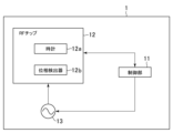
- FIG. 2 is a diagram showing the configuration of a wireless device according to an embodiment of the present invention.
- the wireless device 1 comprises a control unit 11, an RF chip 12, and an oscillator 13.
- the RF chip 12 comprises a clock 12a and a phase detector 12b.
- the wireless device 1 may comprise other components as necessary.
- the control unit 11 is not particularly limited, but may be, for example, a microcomputer (microcontroller).
- the control unit 11 executes a program based on the program and data.
- the RF chip 12 processes the reception and transmission of radio signals.
- the data received by the RF chip 12 is subjected to calculation processing by the control unit 11.
- the oscillator 13 oscillates at a predetermined frequency and outputs a signal to provide operational timing for each part of the device.
- An atomic oscillator or a crystal oscillator can be used as the oscillator 13.
- the clock 12a keeps time using the output signal of the oscillator 13 as the source oscillation and outputs the time.
- the time kept by the clock 12a is controlled by the control unit 11 to be transmitted to the sensor 2 via the RF chip 12.
- the phase detector 12b detects the phase of the carrier wave that constitutes the information received from the sensor 2, and detects the phase of the signal oscillated by the oscillator 13 in the wireless device 1.
- the sensor 2 is not particularly limited as long as it is capable of identifying the position of the sensor itself.
- a GPS sensor, an ultrasonic sensor, an optical sensor, etc. can be used as the sensor 2.
- a sensor capable of identifying the position by using the propagation time of information or a signal can be used as the sensor 2.
- FIG. 3 is a block diagram showing the configuration of a sensor according to an embodiment of the present invention.
- the sensor 2 includes a microprocessor 21, a memory 22, an antenna 23, an RF chip 24, an oscillator 25, and a battery 26.
- the RF chip 24 includes a clock 24a and a phase detector 24b.
- the sensor 2 may include other components as necessary.
- the microprocessor 21 executes programs.
- the RF chip 24 receives and transmits radio signals.
- the data received by the RF chip 24 is processed by the microprocessor 21.
- the electromagnetic waves transmitted from the wireless device 1 are received by the antenna 23.
- the antenna 23 receives the electromagnetic waves, an electrical signal is generated in response. This allows the sensor 2 to receive power from the wireless device 1.
- the microprocessor 21 When the sensor 2 receives power from the wireless device 1, the microprocessor 21 is started and executes a program stored in the microprocessor 21, and the RF chip 24 transmits to the wireless device 1 a wireless signal that can identify the time clocked by the clock 24a and the phase of the carrier wave.
- the battery 26 supplies power to the clock 24a. By supplying power to the clock 24a from the battery 26, the clock 24a can continue to operate even if power is not supplied to the sensor 2 by receiving electromagnetic waves from the wireless device 1.
- the oscillator 25 oscillates at a predetermined frequency and outputs a signal to provide operational timing for each part of the sensor 2.
- An atomic oscillator or a quartz oscillator can be used as the oscillator 25.
- the clock 24a keeps time using the output signal of the oscillator 25 as the source oscillation and outputs the time. The time kept by the clock 24a is controlled by the microprocessor 21 to be transmitted to the wireless device 1 via the RF chip 24.
- the phase detector 24b detects the phase of the carrier wave constituting the information received from the wireless device 1, and detects the phase of the signal oscillated by the oscillator 25 in the sensor 2.
- Sensor 2 is attached to the body of a human or animal.
- the animal is not particularly limited, but is preferably an animal with a skeleton.
- Sensor 2 is preferably attached to a position corresponding to a virtual joint or an end point of a virtual bone of a virtual three-dimensional model (hereinafter, virtual model) set in a virtual space corresponding to the human or animal.
- the virtual model has a virtual skeleton combining multiple virtual bones, and the virtual model can be operated by operating this virtual skeleton.
- the virtual model is preferably human-shaped, and when sensor 2 is attached to an animal, the virtual model is preferably animal-shaped of the same species.
- a virtual bone A that constitutes a virtual skeleton
- a virtual bone B that is directly connected to virtual bone A.
- a virtual bone can be defined by a line that connects two different points, and may be defined by a straight line or a curved line.
- the virtual bone A is almost linear, and the virtual bone B is also almost linear.
- the end points of the virtual bone A are points P and Q, and the end points of the virtual bone B are points Q and R.
- the virtual bones A and B are connected at point Q, which is a virtual joint. For example, if point P corresponds to the shoulder, point Q corresponds to the elbow, and point R corresponds to the hand, then the virtual bone A corresponds to the upper arm, and the virtual bone B corresponds to the forearm.
- the motion of the body can be reproduced by attaching a plurality of sensors 2 to the shoulder, elbow, and back of the hand, respectively, acquiring information on the position of each sensor when the body is moved in association with time, and controlling the motion of the virtual model based on this position information.
- the sensors 2 are attached to positions corresponding to the end points of a plurality of continuously connected virtual bones of any part of the virtual model to be controlled (for example, any part such as the arm, leg, upper body, lower body, or whole body).
- any part such as the arm, leg, upper body, lower body, or whole body.
- the server device 3 can identify the position of the sensor 2 based on the distance from the sensor 2 to the wireless device 1 calculated by a distance calculation process described later.
- the position of the sensor 2 is stored in the server device 3, for example, in association with identification information that can identify the sensor 2 and time.
- the server device 3 can cause the virtual model to reproduce and execute an action that is the same as or similar to an action performed by the user, based on information regarding the positions of multiple sensors 2 over time.
- the server device 3 can save the virtual model performing the reproduced action as video information, and store on the blockchain an NFT associated with information that can be used to access this video information, or request another computer device to store on the blockchain an NFT associated with information that can be used to access this video information.
- FIG. 4 is a block diagram showing the configuration of a server device according to an embodiment of the present invention.
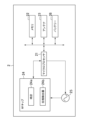
- the server device 3 includes at least a control unit 31, a RAM 32, a storage unit 33, and a communication interface 34, each of which is connected by an internal bus.
- the control unit 31 is composed of a CPU and ROM, and executes programs stored in the storage unit 33 to control the server device 3.
- the control unit 31 also has an internal timer that measures time.
- the RAM 32 is the work area of the control unit 31.
- the storage unit 33 is a memory area for saving programs and data, and functions as a recording medium.
- the control unit 31 reads out programs and data from the RAM 32, and performs program execution processing based on information received from the wireless device 1, etc.
- the server device 3 can be connected to each of the wireless device 1, the user terminal 4, the registration terminal 5, the blockchain 6, and the metadata storage server 7 via a communication network.
- the server device 3 does not have to be a single server device, but may be a combination of multiple server devices. Furthermore, each process in the server device 3 described below may be executed by a single server device, or may be shared and executed by multiple server devices.
- the user terminal 4 is used by the user to access a virtual space such as the metaverse and to operate a virtual model such as an avatar.
- the registration terminal 5 is a terminal used by the user to register the actions he or she desires.
- the user terminal 4 or the registration terminal 5 comprises a control unit, RAM, a storage unit, an input unit, a display unit and a communication interface, each of which is connected by a bus.
- the control unit is composed of a CPU and a ROM.
- the control unit executes programs stored in the storage unit and controls the user terminal 4 or the registration terminal 5.
- the RAM is the work area of the control unit.
- the storage unit is a memory area for saving programs and data, and functions as a recording medium.
- the control unit performs arithmetic processing based on the programs and data read from the RAM, and the data inputted through the input unit.
- the display unit of the user terminal 4 or the registration terminal 5 has a display screen.
- the control unit outputs a video signal for displaying an image on the display screen according to the result of the arithmetic processing.
- the display screen of the display unit may be a touch panel equipped with a touch sensor. In this case, the touch panel functions as the input unit.
- the communication interface of the user terminal 4 or the registration terminal 5 can be connected to a communication network wirelessly or via a wired connection, and can transmit and receive data to and from the server device 3 via the communication network. Data received via the communication interface is loaded into RAM, and calculations are performed by the control unit.
- the same computer device may be used as both the user terminal 4 and the registration terminal 5, or the user terminal 4 and the registration terminal 5 may each be separate computer devices.
- an NFT can be issued in association with the video information.
- Video information is stored in the server device 3.
- information about the video for example, the creator of the video (the person who registered the action) and information explaining the action in the video) and the storage location (URL) of the video information are converted into metadata along with information about the NFT such as the name of the NFT and the issuer of the NFT, and are stored in the metadata storage server 7.
- the blockchain 6 stores the token ID, token holder information, and token transaction history as index data, along with the storage location (URL) of the metadata in the metadata storage server 7.
- the video information is converted into metadata and associated with the NFT.
- the video information may be associated with data associated with the NFT, as long as it is possible to trace the association from the NFT.
- a plurality of sensors 2 are attached to positions on the user's body that correspond to the virtual joints and/or virtual skeleton endpoints of the virtual model.
- the sensors 2 are attached to positions on the body that correspond to the virtual joints and/or virtual skeleton endpoints of the entire body of the virtual model.
- the sensors 2 may be attached over underwear worn by the user, or may be attached over the skin.
- the sensors 2 may also be attached to the body using a belt or the like, or may be attached with adhesive tape or the like.
- FIG. 5 is a diagram showing a flowchart of the action registration process according to an embodiment of the present invention.
- the user or a helper for action registration who is different from the user, operates the registration terminal 5 to start a dedicated application for action registration.
- the user or helper operates the registration terminal 5 to request the start of the action registration operation (step S1). More specifically, the user or helper operates the registration terminal 5 to press a button to start the action registration.
- user identification information that can identify the user may be entered.
- the registration terminal 5 transmits information requesting the start of the action registration operation (hereinafter, operation start request) to the server device 3 (step S2), and the server device 3 receives the operation start request (step S3).
- the server device 3 When the server device 3 receives the operation start request, it requests the wireless device 1 to start identifying the positions of the multiple sensors 2 within the registration space (step S4). Specifically, the server device 3 transmits information requesting the wireless device 1 to start identifying the positions of the sensors 2 (hereinafter, a position identification request). The wireless device 1 receives the position identification request from the server device 3 (step S5).
- step S6 When the wireless device 1 receives the location request, communication between the wireless device 1 and the sensor 2 is initiated, and a distance calculation process between the wireless device 1 and the sensor 2 is executed (step S6).
- the user or collaborator who requested the start of an operation by operating the registration terminal 5 in step S1 confirms that the process for registering an action has started in the real world, and then, while wearing the sensor 2, executes the action that the user wishes to register.
- step S6 for each of the multiple sensors 2 attached to the body, the distance between each of the multiple wireless devices 1 and one sensor 2 is calculated. Details of the distance calculation process will be described later.
- the calculated distance is transmitted from each of the multiple wireless devices 1 to the server device 3 in association with time, sensor identification information that can identify each of the sensors 2, and device identification information that can identify each of the wireless devices 1 (step S7).
- the server device 3 receives the calculated distance transmitted in association with time, sensor identification information that can identify each of the sensors 2, and device identification information that can identify each of the wireless devices 1 (step S8).
- the position of one sensor 2 is identified based on the distances between each of the multiple wireless devices 1 and the sensor 2, and the positions of the multiple wireless devices 1 (step S9). Details of the position identification process in step S9 will be described later.
- the identified position is identified, for example, as coordinate information in a Cartesian coordinate system (XYZ coordinate system) with a specific point in a specific space as the origin.
- the identified positions of the multiple sensors 2 are stored in association with time and sensor identification information of the sensors 2 (step S10).
- steps S6 to S10 is repeatedly executed at predetermined time intervals.
- the predetermined time can be designed as appropriate, but is executed, for example, every 1/30th of a second or 1/60th of a second.
- the processing of steps S6 to S10 is executed until the operation of registering the action is completed. "Until the operation of registering the action is completed" means, for example, until a predetermined time for performing the operation of registering the action has elapsed, or until an input to end the operation of registering the action is made from the registration terminal 5 and information to the effect that the registration operation is completed is received from the registration terminal 5 via the server device 3 by the wireless device 1.
- the time associated with other information is not particularly limited as long as it is information that can identify the time series of the identified position, and may be the actual time or the time elapsed since the operation to register the action was started.
- the time may be the time when the propagation time of the communication between the wireless device 1 and the sensor 2 is measured, the time when the distance between the wireless device 1 and the sensor 2 is calculated, or the time when the position of the sensor 2 is identified, etc.
- step S11 When the action registration operation is completed (step S11), action identification information that can identify the registered action and user identification information that can identify the user are associated with each other and information related to the position of the sensor 2 that changes over time is stored in an action management table set in the storage unit 33 of the server device 3 (step S12).
- step S12 By executing step S12, the series of processes ends. Through these processes, the server device 3 can obtain information related to the positions that change over time for multiple sensors 2 attached to the body.
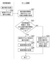
- FIG. 6 is a diagram showing a flowchart of the action execution process according to the embodiment of the present invention.
- a virtual three-dimensional model (hereinafter, referred to as a virtual model) can be set in a virtual space such as a metaverse.
- This virtual model is a concept including so-called characters and avatars.
- it is possible to cause the virtual model in the virtual space to execute an action that reproduces the action of the user.
- the user operates the user terminal to input user identification information, logs into the system 10, and starts operating the virtual model (step S20).
- the user can make the virtual model perform basic actions such as moving, sitting, running, etc.
- the server device 3 receives information capable of identifying the action identification information inputted into the user terminal 4 (step S21)
- the server device 3 refers to the action management table and determines whether the user identification information inputted at the time of login is associated with the action identification information identified by the input (step S22).
- the information capable of identifying the action identification information is not particularly limited, and can be designed as appropriate, such as inputting a specific command or inputting action identification information.
- the position information stored in the movement management table is information corresponding to the positions of virtual joints of virtual bones constituting the virtual model, and/or information corresponding to the positions of end points of virtual bones that are not connected to other virtual bones.
- the positions of the virtual bones of the virtual model are changed over time based on the position information stored in this movement management table that changes over time. This makes it possible to control the movement of a virtual skeleton, which is a combination of multiple virtual bones, and further to control the movement of the virtual model.
- the virtual bones are associated with the vertex coordinates of multiple polygons in order to visualize the virtual model, and when the position of the virtual bone changes, the coordinates of the vertices of the associated polygons also change accordingly.
- the model data of the virtual model made up of these polygons it becomes possible to display the virtual model as a three-dimensional model.
- step S23 a virtual camera is used to perform perspective transformation on the virtual model performing an action in a three-dimensional virtual space, thereby obtaining a two-dimensional moving image (hereinafter referred to as video information) (step S25).
- This video information is stored in the storage unit 33 of the server device 3 (step S26). Steps S21 to S26 complete the virtual model action execution process.
- step S22 By performing a determination such as that in step S22, it is possible to make it possible for only the virtual model corresponding to a specific user to be able to perform a specific action.
- an NFT is issued in association with video information relating to the virtual model's actions, which will be described later, only the virtual model corresponding to the owner of this NFT can be able to perform a specific action. Since the owner of an NFT can transfer ownership to another person, when the owner of an NFT changes, the user who can cause the virtual model to perform a specific action also changes.
- the server device 3 When the server device 3 receives the NFT issuance request (step S32), the server device 3 creates metadata (step S33).
- the metadata includes information related to the NFT, such as the name of the NFT, a description of the NFT, and the URL where the video information is saved.
- the created metadata is then transmitted from the server device 3 to the metadata storage server 7 and uploaded (step S34).
- the URL of the storage location of the uploaded metadata is notified to the server device 3 from the metadata storage server 7.
- the URL of the storage location of the metadata is an example of information that can be used to access the video information.
- the server device 3 embeds the URL of the metadata storage location into the smart contract as a link (step S35), and the smart contract is deployed on the blockchain 6, allowing the NFT to be issued (step S36).
- This associates the NFT with the metadata and makes it possible to track it on the blockchain 6.
- Steps S31 to S36 allow the NFT to be issued in association with video information.
- steps S31 to S36 allow the NFT associated with information that can be used to access the video information to be stored on the blockchain.
- Steps S31 to S36 end the NFT issuance process.
- the NFT issuance process may execute steps S41 to S43 after step S35 instead of step S36.
- the server device 3 transmits a request to issue an NFT associated with the metadata (NFT issuance request) to another server device (step S41).
- the other server device receives the NFT issuance request (step S42), it issues the NFT by deploying the smart contract on the blockchain 6 (step S43).
- step S41 is a process in which the server device 3 requests the other computer device to store on the blockchain an NFT associated with information that can be used to access the video information.
- step S41 may be executed after step S34.
- step S41 information on the URL of the storage location of the metadata is sent to the other server device.
- step S35 is executed in the other server device.
- the server device 3 or another server device may associate the NFT associated with the video information with an account owned by a specific user and store it on the blockchain 6.
- the account owned by the user may use user identification information.
- the account associated with the NFT is preferably the account of the user corresponding to the user terminal 4 that sent the NFT issuance request in step S31.
- the account associated with the NFT is changed to the account of the changed owner. For example, when user A purchases video information associated with the NFT, the NFT is associated with an account owned by user A and stored on the blockchain 6.
- Fig. 8 is a diagram showing a flowchart of the distance calculation process according to the embodiment of the present invention.
- step S51 information or a signal is transmitted from the wireless device 1 to the sensor 2 (step S51).
- the wireless device 1 clocks the time when the information or signal was transmitted in step S51, and measures the phase at the time of transmission (step S52).
- step S52 measures the phase at the time of transmission
- step S53 The clocked time and the measured phase are then stored in the memory in the control unit 11 (step S53).
- the sensor 2 receives the information or signal from the wireless device 1 (step S54).
- the sensor 2 clocks the time when the information or signal was received in step S54, and measures the phase at the time of reception (step S55).
- the clocked time and the measured phase are then stored in the memory 22 (step S56).
- the sensor 2 transmits information or a signal to the wireless device 1 (step S57).
- the sensor 2 clocks the time when the information or signal was transmitted in step S57, and measures the phase at the time of transmission (step S58).
- the clocked time and the measured phase are then stored in the memory 22 (step S59).
- the wireless device 1 receives the information or signal transmitted in step S57 (step S60).
- the wireless device 1 clocks the time when the information or signal was received in step S60 and measures the phase at the time of reception (step S61).
- the clocked time and the measured phase are then stored in the memory of the control unit 11 (step S62).
- step S62 is completed, the process proceeds to step S63.
- the wireless device 1 transmits to the sensor 2 via the RF chip 12 the information stored in step S53 regarding the time when the signal was transmitted in step S51 and the phase at the time of transmission, and the information stored in step S62 regarding the time when the signal was received in step S60 and the phase at the time of reception (step S63).
- the sensor 2 receives information regarding the time and phase at the time when the wireless device 1 transmitted the information or signal in step S51, and information regarding the time and phase at the time when the wireless device 1 received the information or signal in step S60 (step S64).
- the microprocessor 21 of the sensor 2 calculates the phase shift between the phase of the signal generated by the oscillator 13 of the wireless device 1 and the phase of the signal generated by the oscillator 25 of the sensor 2 (step S65).
- the phase shift can be calculated based on the phase difference between the phase of the carrier wave constituting the information or signal transmitted from the wireless device 1 to the sensor 2 and the phase of the signal oscillated by the oscillator 25 of the sensor 2 when the information or signal is received by the sensor 2, and the phase difference between the phase of the carrier wave constituting the information or signal transmitted from the sensor 2 to the wireless device 1 and the phase of the signal oscillated by the oscillator 13 of the wireless device 1 when the information or signal is received by the wireless device 1.
- the phase of the carrier wave constituting the information or signal transmitted from the wireless device 1 to the sensor 2 is the phase of the information or signal transmitted in step S51.
- Information on the phase is transmitted from the wireless device 1 to the sensor 2 in step S63.
- the phase of the signal oscillated by the oscillator 25 of the sensor 2 when the information or signal is received by the sensor 2 is the phase of the information or signal received in step S54.
- Information on the phase is measured by the sensor 2 in step S55 and stored in step S56.
- the phase of the carrier wave constituting the information or signal transmitted from the sensor 2 to the wireless device 1 is, for example, the phase of the information or signal transmitted in step S57. Information on the phase is stored by the sensor 2 in step S59.
- the phase of the signal oscillated by the oscillator 13 of the wireless device 1 when the information or signal is received by the wireless device 1 is, for example, the phase of the information or signal received in step S60.
- Information on the phase is measured in step S61 and transmitted from the wireless device 1 to the sensor 2 in step S63.
- the phase of the carrier wave constituting the information or signal transmitted from wireless device 1 to sensor 2 is a concept that includes not only the phase of the carrier wave constituting the information or signal transmitted from wireless device 1 to sensor 2, but also the phase of the carrier wave constituting the signal obtained by mixing down this information or signal.
- the phase of the carrier wave constituting the information or signal transmitted from sensor 2 to wireless device 1 is a concept that includes not only the phase of the carrier wave constituting the information or signal transmitted from sensor 2 to wireless device 1, but also the phase of the carrier wave constituting the signal obtained by mixing down this information or signal.
- phase difference between the phase of the carrier wave constituting the information or signal transmitted from wireless device 1 to sensor 2 and the phase of the signal oscillated by oscillator 25 of sensor 2 when the information or signal is received by sensor 2 is defined as ⁇ S
- the phase difference between the phase of the carrier wave constituting the information or signal transmitted from sensor 2 to wireless device 1 and the phase of the signal oscillated by oscillator 13 of wireless device 1 when the information or signal is received by wireless device 1 is defined as ⁇ M
- phase shift ⁇ C is calculated by equation (3), but the phase shift ⁇ C to be calculated may be 2 ⁇ or 4 ⁇ , i.e., 2n ⁇ minus. n may be 0 or a positive integer. Therefore, based on the propagation time T P described later and the time difference between the wireless device 1 and the sensor 2, it is possible to determine whether n is 0, 1, or 2 (i.e., whether the value obtained by further subtracting 2n ⁇ from the phase shift ⁇ C calculated by equation (3) is the original phase shift, or whether the value without the subtraction is the original phase shift).
- the signal transmitted from the wireless device 1 to the sensor 2, and the signal transmitted from the sensor 2 to the wireless device 1, may start with an output of any value rather than 0 at the start of transmission. In such a case, it is necessary to measure the phase and transmission time at the start of transmission and correct the phase shift ⁇ C. Note that by keeping the phase at the start of transmission always constant and transmitting at a specified time, it is possible to omit the process of measuring the phase and transmission time at the start of transmission and then correcting ⁇ C.
- step S66 the phase of the signal generated by the oscillator 25 of the sensor 2 is corrected based on the calculated phase shift ⁇ C so as to synchronize with the signal generated by the oscillator 13 of the wireless device 1 (step S66).
- the phase correction in step S66 is controlled and executed by the microprocessor 21.
- the phase shift of the oscillator 25 of the sensor 2 occurs due to the influence of the environment surrounding the sensor 2. By periodically performing the synchronization process in this manner, the clock 24a of the sensor 2 can be made to keep time with high accuracy.
- wireless device 1 calculates the time difference between wireless device 1 and sensor 2 based on the time when wireless device 1 transmits information or a signal to sensor 2, the time when sensor 2 transmits information or a signal to wireless device 1, the time when information or a signal is transmitted from wireless device 1 and received by sensor 2 and clocked, and the time when information or a signal is transmitted from sensor 2 and received by wireless device 1 and clocked (step S67).
- the time when the information or signal is transmitted from the wireless device 1 to the sensor 2 is the time when the information is transmitted in step S51.
- Information about the time is transmitted from the wireless device 1 to the sensor 2 in step S63.
- the time when the information or signal is transmitted from the sensor 2 to the wireless device 1 is the time when the information or signal is transmitted in step S57.
- the information about the time is stored by the sensor 2 in step S59.
- the time when the information or signal is transmitted from the wireless device 1 and received and clocked by the sensor 2 is the time when the information is received in step S54.
- the information about the time is clocked by the sensor 2 in step S55 and stored in step S56.
- the time when the information or signal is transmitted from the sensor 2 and received and clocked by the wireless device 1 is the time when the information or signal is received in step S60.
- the information about the time is clocked in step S61 and transmitted from the wireless device 1 to the sensor 2 in step S63.
- the time in the sensor 2 is corrected based on the calculated time difference so as to be synchronized with the time in the wireless device 1 (step S68). Then, information about the time difference calculated in step S67 is transmitted from the sensor 2 to the wireless device 1 (step S68). The wireless device 1 receives the transmitted information regarding the time difference.
- step S71 the distance between the wireless device 1 and the sensor 2 is calculated (step S71).
- the distance between the wireless device 1 and the sensor 2 is calculated by calculating the propagation time of the information or signal between the wireless device 1 and the sensor 2 based on the substantial difference between the time when the wireless device 1 transmits the information or signal and the time when the information or signal is received by the sensor 2, and multiplying the propagation time by the propagation speed of the information or signal (e.g., the speed of light) to calculate the distance between the wireless device 1 and the sensor 2.
- the difference between the time when the wireless device 1 transmits the information or signal and the time when the sensor 2 receives the information or signal can be calculated based on, for example, the time when the wireless device 1 transmits the information or signal to the sensor 2 in step S51 (the time when the wireless device 1 transmits the information or signal to the sensor 2 in step S63) and the time when the wireless device 1 receives the information or signal at the sensor 2 in step S54, which is stored in the memory 22 in step S56, and the time difference calculated in step S67.
- the distance between the wireless device 1 and the sensor 2 can be calculated by calculating the propagation time for the information or signal to propagate between the wireless device 1 and the sensor 2 based on the substantial difference between the time when the information or signal is transmitted by the sensor 2 and the time when the information or signal is received by the wireless device 1, and multiplying the propagation time by the propagation speed of the information or signal (e.g., the speed of light).
- the difference between the time when the information or signal is transmitted by the sensor 2 and the time when the information or signal is received by the wireless device 1 can be calculated based on, for example, the time when the information or signal is transmitted from the sensor 2 to the wireless device 1 in step S57, which is stored in the memory 22 in step S59, the time when the information or signal is received by the wireless device 1 in step S60 (transmitted from the wireless device 1 to the sensor 2 in step S63), and the time difference calculated in step S67.
- the distance between the wireless device 1 and the sensor 2 calculated in step S71 is stored in the memory in the control unit 11 of the wireless device 1 in association with, for example, time information related to the calculated time, etc., and identification information capable of identifying the wireless device 1 (or position information of the wireless device 1) (step S72). Executing step S72 ends the distance calculation process.
- step S68 it is not necessary to correct the time shift, and it is also possible to calculate the distance between the wireless device 1 and the sensor 2 without correcting the time shift based on the time shift calculated in step S67.
- step S66 it is not necessary to correct the phase shift, and it is also possible to calculate the distance between the wireless device 1 and the sensor 2 without correcting the phase shift.
- the time difference and phase difference between the wireless device 1 and the sensor 2 are corrected and the distance between the wireless device 1 and the sensor 2 is calculated.
- the above-mentioned process of calculating the distance between the wireless device 1 and the sensor 2 can calculate the distance between one sensor 2 and each of multiple wireless devices 1.
- the distance between the wireless device 1 and the sensor 2 is identified for as many wireless devices 1 as necessary to identify the position.
- the distance between wireless device 1 and sensor 2 is calculated by wireless device 1, but the distance between wireless device 1 and sensor 2 may be calculated by sensor 2 instead of wireless device 1 using a process similar to step S71.
- the distance between wireless device 1 and sensor 2 is stored in the memory of control unit 11 in association with time information regarding the calculated time, etc., and identification information capable of identifying wireless device 1.
- the server device 3 may calculate the distance between the wireless device 1 and the sensor 2 by processing similar to that of step S71.
- the information necessary for the calculation is received directly or indirectly from the wireless device 1 and/or the sensor 2.
- the server device 3 calculates the distance the distance between the wireless device 1 and the sensor 2 is stored in the storage unit 33 of the server device 3 in association with time information regarding the calculated time, etc., identification information capable of identifying the wireless device 1 (or position information of the wireless device 1), and identification information capable of identifying the sensor 2.
- the position identification process according to the embodiment of the present invention will be described.
- the distance between one sensor 2 and each of the multiple wireless devices 1 has been calculated in the distance calculation process.
- the position of the sensor 2 (for example, the XYZ coordinates or latitude and longitude of the sensor 2) can be identified based on the distances between one sensor 2 and each of the four wireless devices 1 and the positions of the four wireless devices 1.
- the four wireless devices 1 are not on the same plane.
- the height at which at least one wireless device 1 is installed is different from the height at which the other three wireless devices 1 are installed. In this way, it is possible to identify the position in three dimensions regardless of the position at which the sensor 2 is located.
- the position of the sensor 2 can be identified based on information regarding the position of the sensor 2 relative to the plane, the distances between the one sensor 2 and each of the three wireless devices 1, and the positions of each of the three wireless devices 1. For example, when a user performs an action registration process in a specific room in a building with multiple floors, the system 10 installs the three wireless devices 1 on the specific floor and, by inputting the floor number of the room where the user will perform the action in step S1, can identify the position of the sensor 2 in step S9.
- FIG. 9 is a diagram showing a flowchart of the location identification process according to an embodiment of the present invention.
- the location identification process shown in FIG. 9 can be executed by, for example, the wireless device 1, the sensor 2, or the server device 3.
- information on the distance between each of the multiple wireless devices 1 and the sensor 2 (the distance calculated in step S71) is associated with time information on the calculated time, identification information of the wireless device 1 (or location information of the wireless device 1), and identification information of the sensor 2, and is transmitted to the wireless device 1 or the server device 3 for use.
- the position of the sensor 2 is identified based on the distance between each of the multiple wireless devices 1 and the sensor 2, and the positions of these wireless devices 1 (step S81).
- the positions of the wireless devices may be stored in advance in the storage unit 33 of the server device 3 that executes the position identification process.
- the calculation process for identifying the position of the sensor 2 is not particularly limited.
- the identified position of the sensor 2 is stored in the storage unit 33 of the server device 3 in association with time information on the calculated time (time information on the time when the distance was calculated or time information on the time when the position was identified), identification information of the wireless device 1 (or position information of the wireless device 1), and identification information of the sensor 2 (step S82).
- Steps S81 and S82 end the position identification process.
- the process of step S81 corresponds to the process of step S9.
- the distance between each of the multiple wireless devices 1 and the sensor, which is used to identify the position of the sensor 2 in step S81 is calculated at the same time or a similar time (for example, calculated when the time at which the propagation time of information or signals between each of the multiple wireless devices and the sensor is measured is the same time or a similar time).
- a similar time is not particularly limited, but is preferably a time within a predetermined time range from time 1.
- the positions of multiple sensors attached to multiple different positions on the body of a human or animal are identified at predetermined time intervals, and a virtual model is made to perform an action similar to that of the human or animal based on the identified positions.
- a virtual model is made to perform an action similar to that of the human or animal based on the identified positions.
- control or assist the action of a human or animal in the real world More specifically, this is performed by having the human or animal wear an exoskeleton or wearable robot.
- the exoskeleton or wearable robot is composed of, for example, a structural frame that is attached to the body of the human or animal, and actuators that move joints that connect the structural frames.
- the actuators can be connected to one computer device via communication, and by controlling the operation of the actuators according to instructions from the computer device, it is possible to control or assist the action of a human or animal wearing the exoskeleton or wearable robot.
- server device 3 communicates with and controls an exoskeleton or wearable robot, but it is also possible for the server device 3 to transmit information about the identified location to another computer device, and for the operation of the exoskeleton or wearable robot to be controlled by this other computer device.
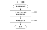
- FIG. 10 is a diagram showing a flowchart of the motion control process according to an embodiment of the present invention.
- the server device 3 calculates a control amount for controlling the motion of one or more actuators incorporated in the exoskeleton or wearable robot based on the sensor positions at each predetermined time stored in step S12 (step S91).
- the motion of the actuator to be calculated may be linear motion or rotational motion.
- the calculation of the control amount can be performed using a known method.
- the server device 3 transmits the calculated control amount of one or more actuators to a control unit or actuator equipped in the exoskeleton or wearable robot (step S92).
- the exoskeleton or wearable robot that receives the control amount controls the actuator based on the received control amount, and as a result, it becomes possible to control or assist the motion of a person or animal wearing the exoskeleton or wearable robot.
- the motion control process ends with steps S91 to S92.
- the motion control process of steps S91 to S92 is repeatedly executed at each predetermined time.
Landscapes
- Engineering & Computer Science (AREA)
- Theoretical Computer Science (AREA)
- Physics & Mathematics (AREA)
- General Physics & Mathematics (AREA)
- Software Systems (AREA)
- Technology Law (AREA)
- Computer Hardware Design (AREA)
- Computer Security & Cryptography (AREA)
- General Engineering & Computer Science (AREA)
- Multimedia (AREA)
- Radar, Positioning & Navigation (AREA)
- Remote Sensing (AREA)
- Arrangements For Transmission Of Measured Signals (AREA)
- Mobile Radio Communication Systems (AREA)
Priority Applications (2)
| Application Number | Priority Date | Filing Date | Title |
|---|---|---|---|
| JP2025511100A JPWO2024204478A1 (https=) | 2023-03-31 | 2024-03-27 | |
| EP24780579.9A EP4693201A1 (en) | 2023-03-31 | 2024-03-27 | Motion authentication system |
Applications Claiming Priority (2)
| Application Number | Priority Date | Filing Date | Title |
|---|---|---|---|
| JP2023059127 | 2023-03-31 | ||
| JP2023-059127 | 2023-03-31 |
Publications (1)
| Publication Number | Publication Date |
|---|---|
| WO2024204478A1 true WO2024204478A1 (ja) | 2024-10-03 |
Family
ID=92905767
Family Applications (1)
| Application Number | Title | Priority Date | Filing Date |
|---|---|---|---|
| PCT/JP2024/012523 Ceased WO2024204478A1 (ja) | 2023-03-31 | 2024-03-27 | 動作認証システム |
Country Status (3)
| Country | Link |
|---|---|
| EP (1) | EP4693201A1 (https=) |
| JP (1) | JPWO2024204478A1 (https=) |
| WO (1) | WO2024204478A1 (https=) |
Citations (9)
| Publication number | Priority date | Publication date | Assignee | Title |
|---|---|---|---|---|
| JP2007322237A (ja) * | 2006-05-31 | 2007-12-13 | Ntt Docomo Inc | サーバ装置、移動端末及び測位方式選択方法 |
| JP2010019597A (ja) * | 2008-07-08 | 2010-01-28 | Fujitsu Ltd | 測位システムおよび測位基地局群 |
| JP2011096114A (ja) * | 2009-10-30 | 2011-05-12 | Brother Industries Ltd | 数値制御装置、工作機械の制御方法、及び工作機械の制御プログラム |
| JP2017129458A (ja) * | 2016-01-20 | 2017-07-27 | 日本電信電話株式会社 | 位置特定システム、および、位置特定方法 |
| JP2019023585A (ja) * | 2017-07-24 | 2019-02-14 | 株式会社ダイヘン | 移動局、測位システム、演算方法及びプログラム |
| WO2020100671A1 (ja) * | 2018-11-15 | 2020-05-22 | ソニー株式会社 | 情報処理装置、情報処理方法及びプログラム |
| JP2020088498A (ja) * | 2018-11-20 | 2020-06-04 | グリー株式会社 | 動画配信システム、動画配信方法、及び動画配信プログラム |
| JP2022177413A (ja) * | 2021-05-18 | 2022-12-01 | グリー株式会社 | 画像処理プログラム、画像処理プログラムおよび画像処理装置 |
| JP2023023825A (ja) * | 2021-08-06 | 2023-02-16 | M Entertainment Works株式会社 | トークン管理プログラム、トークン管理装置、及びトークン管理方法 |
-
2024
- 2024-03-27 JP JP2025511100A patent/JPWO2024204478A1/ja active Pending
- 2024-03-27 EP EP24780579.9A patent/EP4693201A1/en active Pending
- 2024-03-27 WO PCT/JP2024/012523 patent/WO2024204478A1/ja not_active Ceased
Patent Citations (9)
| Publication number | Priority date | Publication date | Assignee | Title |
|---|---|---|---|---|
| JP2007322237A (ja) * | 2006-05-31 | 2007-12-13 | Ntt Docomo Inc | サーバ装置、移動端末及び測位方式選択方法 |
| JP2010019597A (ja) * | 2008-07-08 | 2010-01-28 | Fujitsu Ltd | 測位システムおよび測位基地局群 |
| JP2011096114A (ja) * | 2009-10-30 | 2011-05-12 | Brother Industries Ltd | 数値制御装置、工作機械の制御方法、及び工作機械の制御プログラム |
| JP2017129458A (ja) * | 2016-01-20 | 2017-07-27 | 日本電信電話株式会社 | 位置特定システム、および、位置特定方法 |
| JP2019023585A (ja) * | 2017-07-24 | 2019-02-14 | 株式会社ダイヘン | 移動局、測位システム、演算方法及びプログラム |
| WO2020100671A1 (ja) * | 2018-11-15 | 2020-05-22 | ソニー株式会社 | 情報処理装置、情報処理方法及びプログラム |
| JP2020088498A (ja) * | 2018-11-20 | 2020-06-04 | グリー株式会社 | 動画配信システム、動画配信方法、及び動画配信プログラム |
| JP2022177413A (ja) * | 2021-05-18 | 2022-12-01 | グリー株式会社 | 画像処理プログラム、画像処理プログラムおよび画像処理装置 |
| JP2023023825A (ja) * | 2021-08-06 | 2023-02-16 | M Entertainment Works株式会社 | トークン管理プログラム、トークン管理装置、及びトークン管理方法 |
Also Published As
| Publication number | Publication date |
|---|---|
| JPWO2024204478A1 (https=) | 2024-10-03 |
| EP4693201A1 (en) | 2026-02-11 |
Similar Documents
| Publication | Publication Date | Title |
|---|---|---|
| US11455909B2 (en) | Identification and analysis of movement using sensor devices | |
| CN112041785B (zh) | 跟踪手姿势的方法及其电子设备 | |
| US10860091B2 (en) | Motion predictions of overlapping kinematic chains of a skeleton model used to control a computer system | |
| CN103861265B (zh) | 运动支援装置及运动支援方法 | |
| US11474593B2 (en) | Tracking user movements to control a skeleton model in a computer system | |
| JP6583605B2 (ja) | 運動情報生成装置及び運動情報生成方法、運動情報生成プログラム | |
| JP6152763B2 (ja) | 運動支援装置及び運動支援方法、運動支援プログラム | |
| US20080262772A1 (en) | Sytem and a Method for Motion Tracking Using a Calibration Unit | |
| US20110109628A1 (en) | Method for producing an effect on virtual objects | |
| US20230214027A1 (en) | Reduction of Time Lag Between Positions and Orientations Being Measured and Display Corresponding to the Measurements | |
| US20180147110A1 (en) | Sexual interaction device and method for providing an enhanced computer mediated sexual experience to a user | |
| CN109781104A (zh) | 运动姿态确定及定位方法、装置、计算机设备及介质 | |
| WO2024204478A1 (ja) | 動作認証システム | |
| JP5928036B2 (ja) | タグ位置推定システム、タグ位置推定方法、及びタグ位置推定プログラム | |
| JP6741892B1 (ja) | 測定システム、方法、プログラム | |
| TWM612249U (zh) | 運動訓練輔助裝置 | |
| JP2021137543A (ja) | 測定システム、方法、プログラム | |
| WO2022038664A1 (ja) | 計算装置、歩容計測システム、計算方法、およびプログラム記録媒体 | |
| US20060134583A1 (en) | Simulation and training sphere for receiving persons | |
| JP2017136387A (ja) | 情報表示装置、表示方法およびプログラム | |
| JP2004069468A (ja) | 歩行速度または歩行距離を測定する測定装置 | |
| US20230236218A1 (en) | System and methods for motion tracking | |
| JP7261342B1 (ja) | 情報処理装置、方法、プログラム、およびシステム | |
| JP2012154817A (ja) | 角度測定装置及び方法 | |
| US20240315600A1 (en) | Gait information generation device, gait measurement system, gait information generation method, and recording medium |
Legal Events
| Date | Code | Title | Description |
|---|---|---|---|
| 121 | Ep: the epo has been informed by wipo that ep was designated in this application |
Ref document number: 24780579 Country of ref document: EP Kind code of ref document: A1 |
|
| WWE | Wipo information: entry into national phase |
Ref document number: 2025511100 Country of ref document: JP |
|
| WWE | Wipo information: entry into national phase |
Ref document number: 2024780579 Country of ref document: EP |
|
| NENP | Non-entry into the national phase |
Ref country code: DE |
|
| ENP | Entry into the national phase |
Ref document number: 2024780579 Country of ref document: EP Effective date: 20251031 |
|
| ENP | Entry into the national phase |
Ref document number: 2024780579 Country of ref document: EP Effective date: 20251031 |
|
| ENP | Entry into the national phase |
Ref document number: 2024780579 Country of ref document: EP Effective date: 20251031 |
|
| ENP | Entry into the national phase |
Ref document number: 2024780579 Country of ref document: EP Effective date: 20251031 |
|
| ENP | Entry into the national phase |
Ref document number: 2024780579 Country of ref document: EP Effective date: 20251031 |
|
| ENP | Entry into the national phase |
Ref document number: 2024780579 Country of ref document: EP Effective date: 20251031 |
|
| ENP | Entry into the national phase |
Ref document number: 2024780579 Country of ref document: EP Effective date: 20251031 |
|
| ENP | Entry into the national phase |
Ref document number: 2024780579 Country of ref document: EP Effective date: 20251031 |
|
| WWP | Wipo information: published in national office |
Ref document number: 2024780579 Country of ref document: EP |