WO2024204323A1 - 構造部品 - Google Patents
構造部品 Download PDFInfo
- Publication number
- WO2024204323A1 WO2024204323A1 PCT/JP2024/012218 JP2024012218W WO2024204323A1 WO 2024204323 A1 WO2024204323 A1 WO 2024204323A1 JP 2024012218 W JP2024012218 W JP 2024012218W WO 2024204323 A1 WO2024204323 A1 WO 2024204323A1
- Authority
- WO
- WIPO (PCT)
- Prior art keywords
- structural component
- flange
- curved region
- side wall
- top plate
- Prior art date
- Legal status (The legal status is an assumption and is not a legal conclusion. Google has not performed a legal analysis and makes no representation as to the accuracy of the status listed.)
- Ceased
Links
Images




Classifications
-
- B—PERFORMING OPERATIONS; TRANSPORTING
- B60—VEHICLES IN GENERAL
- B60G—VEHICLE SUSPENSION ARRANGEMENTS
- B60G7/00—Pivoted suspension arms; Accessories thereof
-
- B—PERFORMING OPERATIONS; TRANSPORTING
- B62—LAND VEHICLES FOR TRAVELLING OTHERWISE THAN ON RAILS
- B62D—MOTOR VEHICLES; TRAILERS
- B62D21/00—Understructures, i.e. chassis frame on which a vehicle body may be mounted
Definitions
- This disclosure relates to structural components.
- structures such as the body of an automobile are formed using structural parts.
- Structural parts are required to be durable against input loads.
- Patent Document 1 discloses a suspension arm for automobiles.
- the suspension arm in Patent Document 1 includes a plate-shaped main body and pipe-shaped reinforcing parts provided on both side edges of the main body.
- Patent Document 1 states that this structure increases the second moment of area about an axis that passes through the centroid of the main body and is perpendicular to the main body, thereby providing the suspension arm with sufficient rigidity to withstand bending loads.
- Patent Document 2 discloses a cross member for automobiles.
- the cross member in Patent Document 2 comprises a web folded into a saddle shape, a pair of side walls provided on both side edges of the web, and flanges provided at the tip of each side wall.
- the width of the web gradually increases from both longitudinal ends of the web toward the folded portion.
- Patent Document 2 describes that by making the flange-side tips of the pair of side walls at both longitudinal ends of the web more open than the base end of the web, it is possible to improve the side impact strength when the cross member is connected to a side member for use.
- Some structural parts such as rear upper arms, which are one type of suspension arm for automobiles, include curved regions when viewed from the side. Such structural parts often have a closed cross-sectional structure.
- structural parts with a closed cross-sectional structure called a "monaka structure" are formed by arranging two concave members facing each other and joining them by arc welding.
- rust is likely to occur at arc welded parts, measures must be taken to prevent rust.
- performing arc welding in the manufacturing process of structural parts can increase the manufacturing costs of the structural parts.
- structural components have an open cross-section structure with no arc welds, rusting at the arc welds can be avoided and the manufacturing costs of the structural components can be reduced.
- structural components are simply made to have an open cross-section structure, there is a problem in that the rigidity of the structural components decreases, and the reaction force of the structural components to the input load becomes small.
- the objective of this disclosure is to provide a structural component that can exert a high reaction force against an input load despite having an open cross-section structure.
- the structural component according to the present disclosure includes a top plate, two side walls, and a flange.
- the two side walls are arranged to face each other.
- the two side walls are each continuous with the top plate.
- the flange is continuous with at least one of the two side walls on the opposite side of the top plate.
- the flange protrudes from at least one of the side walls in a direction intersecting the side wall.
- the structural component includes a curved region. When viewed from the side wall side, the curved region is curved with the top plate side being the inside of the curve and the opposite side of the top plate being the outside of the curve. In the curved region, the two side walls are connected by the top plate on the inside of the curve. The curved region opens on the outside of the curve.
- the flange extends along the curved region through the bottom of the curved region on the outside of the curve.
- the protruding length of the flange at the bottom of the curved region is smaller than the protruding length of the flange at both ends of the structural component.
- the structural components disclosed herein are capable of exerting a high reaction force against an input load, despite having an open cross-section structure.
- FIG. 1 is a perspective view of a structural component according to a first embodiment.
- FIG. 2 is a side view of the structural component according to the first embodiment.
- FIG. 3 is a cross-sectional view of the structural component according to the first embodiment.
- FIG. 4 is a partial enlarged view of the structural component according to the first embodiment.
- FIG. 5 is a perspective view of a structural component according to the second embodiment.
- FIG. 6 is a partial enlarged view of a structural component according to the second embodiment.
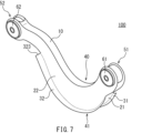
- FIG. 7 is a perspective view of a structural component according to a modified example of the first embodiment.
- FIG. 8 is a perspective view of a structural component according to a modified example of the second embodiment.
- FIG. 1 is a perspective view of a structural component according to a first embodiment.
- FIG. 2 is a side view of the structural component according to the first embodiment.
- FIG. 3 is a cross-sectional view of the structural component according to the first embodiment.
- FIG. 4 is a
- FIG. 9 is a cross-sectional view of a structural component according to a modified example of the first embodiment.
- FIG. 10 is a graph showing the relationship between the extension length of a flange/extension length of a curved region in a structural component and the maximum reaction force.
- FIG. 11 is a graph showing the relationship between the protruding length of a flange in a structural component and the maximum reaction force.
- the structural component according to the embodiment includes a top plate, two side walls, and a flange.
- the two side walls are arranged to face each other.
- the two side walls are each continuous with the top plate.
- the flange is continuous with at least one of the two side walls on the opposite side of the top plate.
- the flange protrudes from at least one of the side walls in a direction intersecting the side wall.
- the structural component includes a curved region. When viewed from the side wall side, the curved region is curved with the top plate side being the inside of the curve and the opposite side of the top plate being the outside of the curve. In the curved region, the two side walls are connected by the top plate on the inside of the curve. The curved region opens on the outside of the curve.
- the flange extends along the curved region through the bottom of the curved region on the outside of the curve.
- the protruding length of the flange at the bottom of the curved region is smaller than the protruding length of the flange at both ends of the structural component (first configuration).
- the structural component according to the first configuration includes a curved region that is curved when viewed from the side wall side of the structural component.
- the top plate is disposed inside the curved region.
- the curved region has an open cross-sectional structure in which the two side walls are connected by the top plate on the inside of the curve, while the outside of the curve is open.
- a flange is provided continuously on at least one of the two side walls. The flange passes through the bottom of the curved region and extends along the curved region.
- the structural component according to the first configuration can exert a high reaction force against the input load, despite having an open cross-sectional structure.
- the protruding length of the flange may be gradually reduced toward at least one end of the structural component (second configuration).
- the length of the flange protruding from the side wall gradually decreases toward the end of the structural component. This reduces the stress that occurs near the end of the structural component, for example, during vibration, compared to when the length of the flange protruding from the end of the structural component is suddenly reduced. This makes it easier to improve the fatigue durability of the structural component.
- the flange may be provided on each of the two side walls (third configuration).
- a flange is provided on each of the two vertical walls. This increases the cross section of the bottom and its vicinity of the curved region, increasing the stiffness of the curved region. This allows the structural component to exert a higher peak reaction force when a compressive load is applied.
- one of the two side walls and the flange provided on that one side wall may be symmetrical with the other side wall and the flange provided on that other side wall with respect to the center of the top plate (fourth configuration).
- two side walls and flanges are provided symmetrically with respect to the center of the top plate in the cross section of the curved region of the structural component. In this case, when a compressive load is applied to the structural component, torsional deformation is less likely to occur in the curved region.
- Fig. 1 is a perspective view that typically shows a structural component 100 according to a first embodiment.
- Fig. 2 is a side view that typically shows the structural component 100.
- the structural component 100 is used, for example, in the body of an automobile.
- the structural component 100 may be, for example, a chassis component such as a suspension arm.
- a chassis component such as a suspension arm.
- the structural component 100 is an upper arm, which is a type of suspension arm.
- the structural component 100 includes a top plate 10, side walls 21, 22, and flanges 31, 32.
- the top plate 10 When the structural component 100, which is the upper arm, is attached to the vehicle, the top plate 10 extends substantially or generally in the left-right direction of the vehicle.
- the direction in which the top plate 10 extends is referred to as the longitudinal direction of the structural component 100.
- the side walls 21, 22 are arranged to face each other.
- the side wall 21 is continuous with the top plate 10.
- the side wall 22 is continuous with the top plate 10 on the side opposite the side wall 21.
- the side walls 21, 22 extend along the top plate 10 in the longitudinal direction of the structural component 100.
- the flanges 31, 32 are continuous with the side walls 21, 22, respectively, on the side opposite the top plate 10.
- the flange 31 protrudes from one side wall 21 in a direction intersecting with the side wall 21.
- the flange 32 protrudes from the other side wall 22 in a direction intersecting with the side wall 22.
- the flanges 31, 32 protrude from the side walls 21, 22, respectively, to the outside of the structural component 100.
- the structural component 100 includes a curved region 40.
- the curved region 40 When viewed from the side wall 21 side, the curved region 40 is curved with the top plate 10 side being the inside of the curve and the opposite side of the top plate 10 being the outside of the curve.
- the curved region 40 When viewed from the side wall 22 side opposite the side wall 21, the curved region 40 is also curved with the top plate 10 side being the inside of the curve and the opposite side of the top plate 10 being the outside of the curve.
- the side walls 21 and 22 are connected by the top plate 10 on the inside of the curve.
- the curved region 40 is open on the outside of the curve. In other words, on the outside of the curve of the curved region 40, the structural component 100 is divided and the side wall 21 and the side wall 22 are separated.
- the opening between the side walls 21 and 22 may be open over the entire longitudinal length of the structural component 100.
- the opening between the side walls 21 and 22 may be blocked in at least a portion of the longitudinal direction of the structural component 100 due to the presence of an inclusion between the side walls 21 and 22.
- the side walls 21 and 22 may be connected by a component separate from the structural component 100.
- the curved region 40 is curved, for example, so as to be concave downward when the structural component 100 is attached to the automobile.
- the curved region 40 extends in the longitudinal direction of the structural component 100 with a radius of curvature of, for example, 400 mm or less.
- the curved region 40 may extend in the longitudinal direction of the structural component 100 with a radius of curvature of, for example, 200 mm or less. It is preferable that the curved region 40 extends in the longitudinal direction of the structural component 100 with a radius of curvature of, for example, 150 mm or less.
- the radius of curvature of the curved region 40 is, for example, 20 mm or more, and preferably 50 mm or more.
- the radius of curvature in this case is the radius of curvature of the inner side of the curve of the curved region 40.
- Mounting portions 51, 52 are provided at both longitudinal ends of the structural component 100.
- the mounting portions 51, 52 are portions for mounting the structural component 100 to other components.
- the top plate 10 extends from the vicinity of one mounting portion 51 to the vicinity of the other mounting portion 52.
- the mounting portions 51, 52 may be, for example, burring portions formed on the side walls 21, 22.
- bushings 61, 62 are press-fitted into the mounting portions 51, 52, respectively.
- the form of the mounting portions 51, 52 is not limited to this.
- the flanges 31, 32 pass through the bottom 41 of the curved region 40 and extend along the curved region 40. In this embodiment, the flanges 31, 32 extend to near both ends of the structural component 100 in the longitudinal direction. However, the flanges 31, 32 do not reach both ends of the structural component 100.
- the extension length of the flange 31 in the longitudinal direction of the structural component 100 can be determined, for example, based on the extension length of the curved region 40.
- the extension length of the curved region 40 is the line length (perimeter) of the curved region 40 on the outside of the curve. More specifically, the extension length of the curved region 40 is the length of the curved range extending in the structural component 100 with the top plate 10 side as the inside of the curve and the flange 31 side as the outside of the curve, and is measured along the boundary between the side wall 21 and the flange 31.
- the extension length of the flange 31 is typically greater than 15% of the extension length of the curved region 40. It is preferable that the extension length of the flange 31 be 20% or more of the extension length of the curved region 40.
- the extension length of the flange 32 in the longitudinal direction of the structural component 100 may be equal to or different from the extension length of the flange 31.
- the extension length of the flange 32 can also be determined based on the extension length of the curved region 40. In this case, the extension length of the curved region 40 is measured along the boundary between the side wall 22 and the flange 32.
- the extension length of the curved region 40 is the length of the curved range in the structural component 100 that extends with the top plate 10 side as the inside of the curve and the flange 32 side as the outside of the curve.
- the extension length of the flange 32 is typically 15% or more of the extension length of the curved region 40. It is preferable that the extension length of the flange 32 is 30% or more of the extension length of the curved region 40.
- each of the flanges 31, 32 is less than the entire longitudinal length of the structural component 100.
- the flanges 31, 32 extend along the longitudinal direction of the structural component 100, but the flanges 31, 32 are not present at both longitudinal ends of the structural component 100.
- the flanges 31, 32 may be disposed between the mounting portions 51 and 52 in the longitudinal direction of the structural component 100. In other words, the flanges 31, 32 do not reach the mounting portions 51, 52, and the flanges 31, 32 may not be present at the positions of the mounting portions 51, 52.
- Figure 3 is a diagram showing a cross section (transverse section) of the structural component 100 when cut along a plane perpendicular to the longitudinal direction.
- Figure 3 shows the III-III section of Figure 2, i.e., the transverse section of the structural component 100 at the position of the bottom 41 of the curved region 40.
- the tabletop 10 includes a tabletop body 11 and ridge portions 121 and 122.
- the tabletop body 11 has a substantially flat shape when viewed in a cross section of the structural component 100.
- the ridge portions 121 and 122 are provided continuously on both side edges of the tabletop body 11.
- the ridge portion 121 is a corner portion between the tabletop body 11 and one side wall 21.
- the ridge portion 122 is a corner portion between the tabletop body 11 and the other side wall 22.
- the ridge portions 121 and 122 have, for example, a substantially arc shape when viewed in a cross section of the structural component 100.
- the side walls 21, 22 are provided contiguous to the ridges 121, 122 of the tabletop 10, respectively.
- the space between the two side walls 21, 22 is open on the opposite side of the tabletop 10. That is, the structural component 100 has an open cross-sectional structure at least in the range of the curved region 40.
- the structural component 100 can also have an open cross-sectional structure over the entire or almost entire longitudinal direction.
- An open cross-sectional structure means that on the opposite side of the tabletop 10, the ends of the side walls 21, 22 are spaced apart from each other, and the structural component 100 itself does not have a continuous structure.
- the flange 31 includes a ridge portion 311 and a flange body 312.
- the flange 32 includes a ridge portion 321 and a flange body 322.
- the ridge portions 311 and 321 have, for example, a substantially arc shape in a cross-sectional view of the structural component 100.
- the flange bodies 312 and 322 protrude from the ridge portions 311 and 321, respectively, to the outside of the structural component 100.
- the flange bodies 312 and 322 are substantially parallel to the top plate body 11 in a cross-sectional view of the curved region 40.
- the flange bodies 312 and 322 may be inclined with respect to the top plate body 11.
- one side wall 21 and the flange 31 provided on the side wall 21 are symmetrical with the other side wall 22 and the flange 32 provided on the side wall 22 with respect to the center of the tabletop 10.
- the side wall 21 and the flange 31 are provided symmetrical with the side wall 22 and the flange 32 with respect to the center line CL of the tabletop 10, which passes through the midpoint of a line connecting the boundary between the tabletop 10 and the side wall 21, i.e., the R end of the ridge portion 121 on the side wall 21 side, and the boundary between the tabletop 10 and the side wall 22, i.e., the R end of the ridge portion 122 on the side wall 22 side, and is perpendicular to the line.
- the side wall 21 and the flange 31 are symmetrical with the side wall 22 and the flange 32 with respect to the center of the tabletop 10, at least over the entire length of the curved region 40.
- the flanges 31 and 32 have protruding lengths L 1 and L 2 , respectively.
- the protruding length L 1 of the flange 31 is the linear distance from the boundary between the side wall 21 and the ridge line portion 311 to the free end of the flange main body 312 in the cross-sectional view of the structural component 100.
- the protruding length L 2 of the flange 32 is the linear distance from the boundary between the side wall 22 and the ridge line portion 321 to the free end of the flange main body 322 in the cross-sectional view of the structural component 100.
- the protruding lengths L 1 and L 2 of the flanges 31 and 32 at the bottom 41 (FIGS.
- the flanges 31 and 32 do not reach both ends of the structural component 100 in the longitudinal direction, so the protruding lengths L 1 and L 2 of the flanges 31 and 32 at both ends of the structural component 100 are zero.
- the protruding length L1 of the flange 31 is preferably greater at the bottom 41 of the curved region 40 (FIGS. 1 and 2) than at one end or both ends in the longitudinal direction of the structural component 100.
- the protruding length L1 may be maximum, for example, at the bottom 41 of the curved region 40.
- the portion of the flange 31 where the protruding length L1 is maximum may extend in the longitudinal direction of the structural component 100 through the bottom 41 of the curved region 40.
- the protruding length L2 of the flange 32 is preferably greater at the bottom 41 of the curved region 40 than at one end or both ends in the longitudinal direction of the structural component 100.
- the protruding length L2 may be maximum, for example, at the bottom 41 of the curved region 40.
- the portion of the flange 32 where the protruding length L2 is maximum may extend in the longitudinal direction of the structural component 100 through the bottom 41 of the curved region 40.
- the protruding length L2 of the flange 32 gradually decreases from one end of the structural component 100 toward the one end. More specifically, the end face 323 of the flange 31 in the extending direction has a curved shape and smoothly continues to the side wall 22 at one end of the structural component 100, so that the flange 32 gradually disappears toward the one end of the structural component 100.
- the protruding length L2 of the flange 32 gradually decreases toward the other end of the structural component 100 in the longitudinal direction as well. Even at the other end of the structural component 100, the end face of the flange 32 in the extending direction can have a curved shape that smoothly continues to the side wall 22.
- the flange 31 can have a similar configuration to the flange 32. That is, the protruding length L1 of the flange 31 gradually decreases from one end side in the longitudinal direction of the structural component 100 toward the one end, similar to the protruding length L2 of the flange 32. It is preferable that the protruding length L1 of the flange 31 also gradually decreases from the other end side in the longitudinal direction of the structural component 100 toward the other end. Similar to the flange 32, both end faces of the flange 31 in the extension direction can have a curved shape so as to smoothly continue to the side wall 21.
- the cross section of the structural component 100 is expanded at the bottom 41 of the curved region 40, where bending deformation is concentrated when a compressive load that compresses the mounting portions 51 and 52 is input to the structural component 100, and in the vicinity thereof, and the peak reaction force against the compressive load can be increased. Therefore, the structural component 100 can exert a high peak reaction force against the input load despite having an open cross-sectional structure.
- the protruding length L1 of the flange 31 from the side wall 21 is gradually reduced from one end side in the longitudinal direction of the structural component 100 toward the one end.
- the protruding length L2 of the flange 32 from the side wall 22 is gradually reduced from one end side in the longitudinal direction of the structural component 100 toward the one end. That is, the protruding lengths L1 , L2 of the flanges 31, 32 are gradually reduced at one end side of the structural component 100. This reduces stress concentration near one end of the structural component 100, making it easier to improve the fatigue durability of the structural component 100.
- the protruding lengths L1 , L2 of the flanges 31, 32 are also gradually reduced toward the other end at the other end side in the longitudinal direction of the structural component 100.
- the protruding lengths L1 , L2 of the flanges 31, 32 at the bottom 41 of the curved region 40 are smaller than the protruding lengths L1 , L2 of the flanges 31, 32 at both ends in the longitudinal direction of the structural component 100. More specifically, the protruding lengths L1 , L2 of the flanges 31, 32 are zero at both ends of the structural component 100. In this case, for example, when the structural component 100 is attached to another component via the attachment portions 51, 52, the flanges 31, 32 are less likely to interfere with the layout of the other component relative to the structural component 100.
- one side wall 21 and flange 31 are provided symmetrically with the other side wall 22 and flange 32 with respect to the center of the top plate 10. This suppresses the occurrence of torsional deformation in the curved region 40 when a compressive load is input to the structural component 100.
- the side wall 21 and the flange 31 do not necessarily have to be symmetrical with the side wall 22 and the flange 32 with respect to the center of the tabletop 10.
- the protruding length L1 of the flange 31 may be different from the protruding length L2 of the flange 32.
- the angle between the side wall 21 and the tabletop main body 11 may be different from the angle between the side wall 22 and the tabletop main body 11, and the flange 31 may be non-parallel to the flange 32.
- FIG. 5 is a perspective view of a structural component 200 according to the second embodiment.
- the structural component 200 according to this embodiment has basically the same configuration as the structural component 100 according to the first embodiment (FIGS. 1 to 4). However, the structural component 200 differs from the structural component 100 according to the first embodiment in part of the configuration of the flanges 31, 32.
- the extension length of the flanges 31, 32 exceeds the extension length of the curved region 40.
- the extension length of the flanges 31, 32 may be equal to or less than the extension length of the curved region 40, but may also exceed the extension length of the curved region 40 as in this embodiment.
- FIG. 6 is a partial enlarged view of the flange 32 at one end side in the longitudinal direction of the structural component 200.
- the protruding length L2 of the flange 32 gradually decreases from one end side of the structural component 200 toward the one end.
- the end face 323 is inclined with respect to the extending direction of the flange 32. The end face 323 approaches the side wall 22 as it approaches the one end of the structural component 200 and continues at an obtuse angle with the side wall 22. As a result, the flange 32 gradually disappears toward the one end of the structural component 200.
- the end face of the flange 32 may also be inclined with respect to the extending direction of the flange 32 and continue at an obtuse angle with the side wall 22 at the other end side in the longitudinal direction of the structural component 200.
- stress concentration near the end of the structural component 200 is reduced, and the fatigue durability of the structural component 200 is easily improved.
- the flange 31 can have a similar configuration to the flange 32. That is, at one end of the structural component 200 in the longitudinal direction, the end face of the flange 31 can be inclined with respect to the extension direction of the flange 31 and can be continuous with the side wall 21 at an obtuse angle. At the other end of the structural component 200 in the longitudinal direction, the end face of the flange 31 can also be inclined with respect to the extension direction of the flange 31 and can be continuous with the side wall 21 at an obtuse angle.
- Such an end face shape of the flanges 31, 32 may be applied to the structural component 100 according to the first embodiment.
- the end face shape of the flanges 31, 32 of the structural component 100 according to the first embodiment may be applied to the structural component 200 according to this embodiment.
- the end face shapes of the flanges 31, 32 are not limited to the shapes described in the first and present embodiments.
- the shapes of both longitudinal end faces of the flanges 31, 32 do not necessarily have to be the same, and the end face shape of the flange 31 does not necessarily have to be the same as the end face shape of the flange 32.
- the flanges 31, 32 are configured such that the protruding lengths L1 , L2 gradually decrease toward the ends of the structural components 100, 200.
- the protruding lengths of the flanges 31, 32 may be suddenly decreased at the ends of the structural components 100, 200.
- the protruding lengths L1 , L2 of the flanges 31, 32 gradually change at one or both ends of the structural components 100, 200, as in the above embodiment.
- the protruding lengths L1 , L2 change at one end or both ends of the flanges 31 , 32 in the extension direction, but are substantially constant in other parts.
- the protruding lengths L1 , L2 may change over the entire flanges 31, 32 or in parts other than the end sides of the structural component 100, 200.
- the protruding lengths L1 , L2 of the flanges 31, 32 may gradually decrease from the bottom 41 of the curved region 40 or its vicinity toward the end of the structural component 100 or 200.
- flanges 31 and 32 are provided on the side walls 21 and 22, respectively, which are continuous with each other on the opposite side of the top plate 10.
- the structural components 100 and 200 do not necessarily have to have either of the flanges 31 and 32.
- Figures 10 and 11 are graphs showing the results of this analysis.
- Figure 10 shows the relationship between the ratio (%) of the flange extension length to the extension length of the curved region and the maximum reaction force (kN).
- Figure 10 shows the results of an analysis obtained by fixing the flange protruding length to 10 mm and varying the ratio of the flange extension length to the extension length of the curved region.
- Figure 11 shows the relationship between the flange protruding length (mm) and the maximum reaction force (kN).
- Figure 11 shows the results of an analysis obtained by fixing the ratio of the flange extension length to the extension length of the curved region to 100% and varying the flange protruding length.
- the maximum reaction force in Figures 10 and 11 is the ratio to the maximum reaction force of a structural part (open cross-section structure) in which no flanges are provided on both side walls, i.e., the flange protruding length is zero.
- the extension length of the flange is preferably 20% or more of the extension length of the curved region.
- the greater the flange protruding length the greater the maximum reaction force. Therefore, from the perspective of maximum reaction force, it is better for the flange to have a greater protruding length.
- the flange protruding length is determined taking into consideration factors such as the weight of the structural part and its relationship with other parts placed around the structural part.
Landscapes
- Engineering & Computer Science (AREA)
- Mechanical Engineering (AREA)
- Chemical & Material Sciences (AREA)
- Combustion & Propulsion (AREA)
- Transportation (AREA)
- Body Structure For Vehicles (AREA)
Priority Applications (1)
| Application Number | Priority Date | Filing Date | Title |
|---|---|---|---|
| JP2025511012A JP7820680B2 (ja) | 2023-03-27 | 2024-03-27 | 構造部品 |
Applications Claiming Priority (2)
| Application Number | Priority Date | Filing Date | Title |
|---|---|---|---|
| JP2023049327 | 2023-03-27 | ||
| JP2023-049327 | 2023-03-27 |
Publications (1)
| Publication Number | Publication Date |
|---|---|
| WO2024204323A1 true WO2024204323A1 (ja) | 2024-10-03 |
Family
ID=92906676
Family Applications (1)
| Application Number | Title | Priority Date | Filing Date |
|---|---|---|---|
| PCT/JP2024/012218 Ceased WO2024204323A1 (ja) | 2023-03-27 | 2024-03-27 | 構造部品 |
Country Status (2)
| Country | Link |
|---|---|
| JP (1) | JP7820680B2 (https=) |
| WO (1) | WO2024204323A1 (https=) |
Citations (1)
| Publication number | Priority date | Publication date | Assignee | Title |
|---|---|---|---|---|
| JPS6252003U (https=) * | 1985-09-21 | 1987-03-31 |
-
2024
- 2024-03-27 JP JP2025511012A patent/JP7820680B2/ja active Active
- 2024-03-27 WO PCT/JP2024/012218 patent/WO2024204323A1/ja not_active Ceased
Patent Citations (1)
| Publication number | Priority date | Publication date | Assignee | Title |
|---|---|---|---|---|
| JPS6252003U (https=) * | 1985-09-21 | 1987-03-31 |
Also Published As
| Publication number | Publication date |
|---|---|
| JPWO2024204323A1 (https=) | 2024-10-03 |
| JP7820680B2 (ja) | 2026-02-26 |
Similar Documents
| Publication | Publication Date | Title |
|---|---|---|
| JP3725031B2 (ja) | サスペンションアーム | |
| EP2010410B1 (en) | Seat back frame for a vehicle | |
| US6419302B2 (en) | Channel member for constructing elongated wall portion of vehicle body | |
| JP2024541373A (ja) | 車両用サイドシル | |
| WO2019103152A1 (ja) | 構造部材 | |
| JP3056178B2 (ja) | トーションビーム式サスペンション | |
| JP7820680B2 (ja) | 構造部品 | |
| US20160159405A1 (en) | Vehicular floor brace | |
| JP7288179B2 (ja) | 継手構造 | |
| JP2003534961A (ja) | 切り欠かれた横桁を有するリヤアクスル | |
| CN111746216A (zh) | 扭力梁式悬架 | |
| KR20230159877A (ko) | 서스펜션 아암 | |
| JP7799233B2 (ja) | 構造部品 | |
| JP7175809B2 (ja) | ラダーフレーム補強構造 | |
| JP7846438B2 (ja) | 構造部品 | |
| JP7368730B2 (ja) | リアサブフレーム | |
| JP2024541325A (ja) | 車両用サイドシル | |
| JP7538461B1 (ja) | 構造部品 | |
| JP7538462B1 (ja) | 構造部材 | |
| KR101185357B1 (ko) | 스프링백을 이용하여 개선된 보강 구조를 갖는 로암 및 그 제조 방법 | |
| JP2003261072A (ja) | 車両骨格部材構造 | |
| JP7186812B2 (ja) | サスペンション | |
| WO2024210057A1 (ja) | 構造部材 | |
| JP7560792B2 (ja) | 構造部品 | |
| JP2024126603A (ja) | 構造部材 |
Legal Events
| Date | Code | Title | Description |
|---|---|---|---|
| 121 | Ep: the epo has been informed by wipo that ep was designated in this application |
Ref document number: 24780429 Country of ref document: EP Kind code of ref document: A1 |
|
| WWE | Wipo information: entry into national phase |
Ref document number: 2025511012 Country of ref document: JP |
|
| NENP | Non-entry into the national phase |
Ref country code: DE |
|
| 122 | Ep: pct application non-entry in european phase |
Ref document number: 24780429 Country of ref document: EP Kind code of ref document: A1 |