WO2024204176A1 - 冷凍装置 - Google Patents
冷凍装置 Download PDFInfo
- Publication number
- WO2024204176A1 WO2024204176A1 PCT/JP2024/011913 JP2024011913W WO2024204176A1 WO 2024204176 A1 WO2024204176 A1 WO 2024204176A1 JP 2024011913 W JP2024011913 W JP 2024011913W WO 2024204176 A1 WO2024204176 A1 WO 2024204176A1
- Authority
- WO
- WIPO (PCT)
- Prior art keywords
- refrigerant
- compressor
- state
- gas
- flow path
- Prior art date
- Legal status (The legal status is an assumption and is not a legal conclusion. Google has not performed a legal analysis and makes no representation as to the accuracy of the status listed.)
- Ceased
Links
Images




Classifications
-
- F—MECHANICAL ENGINEERING; LIGHTING; HEATING; WEAPONS; BLASTING
- F25—REFRIGERATION OR COOLING; COMBINED HEATING AND REFRIGERATION SYSTEMS; HEAT PUMP SYSTEMS; MANUFACTURE OR STORAGE OF ICE; LIQUEFACTION SOLIDIFICATION OF GASES
- F25B—REFRIGERATION MACHINES, PLANTS OR SYSTEMS; COMBINED HEATING AND REFRIGERATION SYSTEMS; HEAT PUMP SYSTEMS
- F25B1/00—Compression machines, plants or systems with non-reversible cycle
- F25B1/10—Compression machines, plants or systems with non-reversible cycle with multi-stage compression
-
- F—MECHANICAL ENGINEERING; LIGHTING; HEATING; WEAPONS; BLASTING
- F25—REFRIGERATION OR COOLING; COMBINED HEATING AND REFRIGERATION SYSTEMS; HEAT PUMP SYSTEMS; MANUFACTURE OR STORAGE OF ICE; LIQUEFACTION SOLIDIFICATION OF GASES
- F25B—REFRIGERATION MACHINES, PLANTS OR SYSTEMS; COMBINED HEATING AND REFRIGERATION SYSTEMS; HEAT PUMP SYSTEMS
- F25B40/00—Subcoolers, desuperheaters or superheaters
-
- F—MECHANICAL ENGINEERING; LIGHTING; HEATING; WEAPONS; BLASTING
- F25—REFRIGERATION OR COOLING; COMBINED HEATING AND REFRIGERATION SYSTEMS; HEAT PUMP SYSTEMS; MANUFACTURE OR STORAGE OF ICE; LIQUEFACTION SOLIDIFICATION OF GASES
- F25B—REFRIGERATION MACHINES, PLANTS OR SYSTEMS; COMBINED HEATING AND REFRIGERATION SYSTEMS; HEAT PUMP SYSTEMS
- F25B49/00—Arrangement or mounting of control or safety devices
- F25B49/02—Arrangement or mounting of control or safety devices for compression type machines, plants or systems
-
- F—MECHANICAL ENGINEERING; LIGHTING; HEATING; WEAPONS; BLASTING
- F25—REFRIGERATION OR COOLING; COMBINED HEATING AND REFRIGERATION SYSTEMS; HEAT PUMP SYSTEMS; MANUFACTURE OR STORAGE OF ICE; LIQUEFACTION SOLIDIFICATION OF GASES
- F25B—REFRIGERATION MACHINES, PLANTS OR SYSTEMS; COMBINED HEATING AND REFRIGERATION SYSTEMS; HEAT PUMP SYSTEMS
- F25B2400/00—General features or devices for refrigeration machines, plants or systems, combined heating and refrigeration systems or heat-pump systems, i.e. not limited to a particular subgroup of F25B
- F25B2400/04—Refrigeration circuit bypassing means
- F25B2400/0401—Refrigeration circuit bypassing means for the compressor
-
- F—MECHANICAL ENGINEERING; LIGHTING; HEATING; WEAPONS; BLASTING
- F25—REFRIGERATION OR COOLING; COMBINED HEATING AND REFRIGERATION SYSTEMS; HEAT PUMP SYSTEMS; MANUFACTURE OR STORAGE OF ICE; LIQUEFACTION SOLIDIFICATION OF GASES
- F25B—REFRIGERATION MACHINES, PLANTS OR SYSTEMS; COMBINED HEATING AND REFRIGERATION SYSTEMS; HEAT PUMP SYSTEMS
- F25B2400/00—General features or devices for refrigeration machines, plants or systems, combined heating and refrigeration systems or heat-pump systems, i.e. not limited to a particular subgroup of F25B
- F25B2400/13—Economisers
-
- F—MECHANICAL ENGINEERING; LIGHTING; HEATING; WEAPONS; BLASTING
- F25—REFRIGERATION OR COOLING; COMBINED HEATING AND REFRIGERATION SYSTEMS; HEAT PUMP SYSTEMS; MANUFACTURE OR STORAGE OF ICE; LIQUEFACTION SOLIDIFICATION OF GASES
- F25B—REFRIGERATION MACHINES, PLANTS OR SYSTEMS; COMBINED HEATING AND REFRIGERATION SYSTEMS; HEAT PUMP SYSTEMS
- F25B2500/00—Problems to be solved
- F25B2500/26—Problems to be solved characterised by the startup of the refrigeration cycle
-
- F—MECHANICAL ENGINEERING; LIGHTING; HEATING; WEAPONS; BLASTING
- F25—REFRIGERATION OR COOLING; COMBINED HEATING AND REFRIGERATION SYSTEMS; HEAT PUMP SYSTEMS; MANUFACTURE OR STORAGE OF ICE; LIQUEFACTION SOLIDIFICATION OF GASES
- F25B—REFRIGERATION MACHINES, PLANTS OR SYSTEMS; COMBINED HEATING AND REFRIGERATION SYSTEMS; HEAT PUMP SYSTEMS
- F25B31/00—Compressor arrangements
- F25B31/002—Lubrication
- F25B31/004—Lubrication oil recirculating arrangements
Definitions
- Patent Document 1 JP Patent Publication 2016-128734 A
- a refrigeration system that uses carbon dioxide as a refrigerant and has a two-stage compression mechanism consisting of a low-stage compressor and a high-stage compressor. This refrigeration system is used to cool the air in a target space by the heat absorption effect of a refrigerant evaporator installed in the target space.
- the refrigeration device of the first aspect includes a refrigerant circuit in which a first compressor, a second compressor, a first heat exchanger, an expansion mechanism, and a second heat exchanger are connected in sequence.
- the first heat exchanger functions as a heat radiator for the refrigerant compressed by the first compressor or the second compressor.
- the second heat exchanger functions as a heat absorber for the refrigerant decompressed by the expansion mechanism.
- the refrigerant circuit has a gas-liquid separator or a third heat exchanger, a first flow path, a second flow path, and a third flow path.
- the gas-liquid separator separates the refrigerant in a two-phase gas-liquid state decompressed by the expansion mechanism into liquid refrigerant and gas refrigerant.
- the third heat exchanger exchanges heat between the refrigerant decompressed by the decompression mechanism after heat dissipation in the first heat exchanger, and the refrigerant after heat dissipation in the first heat exchanger and before being decompressed by the expansion mechanism.
- the first flow path connects the gas-liquid separator or the third heat exchanger to the suction side of the second compressor.
- the second flow path connects the discharge side of the first compressor and the suction side of the second compressor.
- the third flow path connects the discharge side of the first compressor and the discharge side of the second compressor.
- the first flow path guides the gas refrigerant in the gas-liquid separator, or the refrigerant that has been depressurized by the decompression mechanism and heat exchanged in the third heat exchanger, to the suction side of the second compressor.
- the second flow path guides the refrigerant discharged from the first compressor to the suction side of the second compressor.
- the third flow path guides the refrigerant discharged from the first compressor to the discharge side of the second compressor when the refrigerant discharged from the first compressor is not flowing through the second flow path.
- the refrigeration system of the first aspect can perform two-stage compression operation using a low-stage compressor and a high-stage compressor, and single-stage compression operation using only the low-stage compressor.
- this refrigeration system can ensure the compression ratio of the low-stage compressor and maintain a high pressure for the high-pressure side refrigerant. Therefore, the refrigeration system of the first aspect can suppress a decrease in capacity during pull-down operation.
- the refrigeration device of a second aspect is the refrigeration device of the first aspect, further comprising a control unit that switches the refrigerant circuit between a first state and a second state.
- the refrigerant discharged from the first compressor flows through the second flow path, merges with the gas refrigerant flowing through the first flow path, and is sucked into the second compressor.
- the refrigerant discharged from the first compressor flows through the third flow path without flowing through the second flow path, and merges with the refrigerant discharged from the second compressor.
- the refrigerant circuit further includes a first valve provided in the second flow path, and a second valve that is a check valve provided in the third flow path.
- the control unit opens the first valve in the first state, and closes the first valve in the second state.
- the refrigeration device of the second aspect can switch between a state in which two-stage compression operation is performed and a state in which single-stage compression operation is performed by controlling the opening and closing of a valve provided in the refrigerant circuit.
- the refrigeration device of the third aspect is the refrigeration device of the second aspect, and the control unit switches the refrigerant circuit from the second state to the first state when the temperature of the refrigerant sucked into the first compressor drops to a first value and the temperature of the refrigerant discharged from the first compressor rises to a second value while the refrigerant circuit is in the second state.
- the refrigeration system of the third aspect transitions to a state of two-stage compression operation when the load on the low-stage compressor increases during single-stage compression operation. Therefore, the refrigeration system of the third aspect can reduce the load on the low-stage compressor and suppress a decrease in the reliability of the low-stage compressor.
- the refrigeration device of the fourth aspect is the refrigeration device of the second or third aspect, and the control unit switches the refrigerant circuit from the first state to the second state when the temperature of the refrigerant sucked into the first compressor rises to a third value or when the rotation speed of the first compressor falls below the rotation speed of the second compressor while the refrigerant circuit is in the first state.
- the refrigeration system of the fourth aspect transitions to a state of single-stage compression operation when the load on the high-stage compressor increases during two-stage compression operation. Therefore, the refrigeration system of the fourth aspect can reduce the load on the high-stage compressor and suppress a decrease in the reliability of the high-stage compressor.
- the refrigeration device of a fifth aspect is the refrigeration device of any one of the second to fourth aspects, in which the control unit switches the refrigerant circuit between a first state, a second state, and a third state. In the third state, no refrigerant is drawn into the second compressor, and the refrigerant discharged from the first compressor flows through the third flow path without flowing through the second flow path.
- the refrigerant circuit further has a third valve provided in the first flow path. The control unit opens the third valve in the first state or the second state, and closes the third valve in the third state.
- switching between a state in which degassing operation is performed, in which the gas refrigerant in the gas-liquid separator is compressed by the high-stage compressor, and a state in which degassing operation is not performed can be performed by controlling the opening and closing of a valve provided in the refrigerant circuit.
- the refrigeration device of the sixth aspect is the refrigeration device of the fifth aspect, in which the control unit switches the refrigerant circuit in the order of the third state, the second state, and the first state when the first compressor and the second compressor are started.
- the refrigeration system of the sixth aspect performs control so that, at startup, degassing operation is not performed when the amount of refrigerant on the high-pressure side is small, and degassing operation is started when the amount of refrigerant on the high-pressure side increases. Therefore, the refrigeration system of the sixth aspect can reduce the load on the high-pressure side compressor and suppress a decrease in capacity.
- the refrigeration device of the seventh aspect is the refrigeration device of any one of the first to sixth aspects, in which the refrigerant circuit has a gas-liquid separator and further has a fourth flow path.
- the fourth flow path connects the gas-liquid separator and the first flow path.
- the fourth flow path guides the refrigeration oil in the gas-liquid separator, together with the liquid refrigerant in the gas-liquid separator, to the suction side of the second compressor via the first flow path.
- the refrigeration system of the seventh aspect can prevent a shortage of refrigeration oil in the high-pressure compressor.
- the refrigeration device of an eighth aspect is the refrigeration device of any one of the first to seventh aspects, and the refrigerant circuit further has a fifth flow path.
- the fifth flow path connects the discharge side of the second compressor to the suction side of the second compressor.
- the fifth flow path guides the refrigeration oil discharged from the second compressor to the suction side of the second compressor.
- the fifth flow path is provided with an oil separator for separating the refrigeration oil from the mixture of the refrigerant and the refrigeration oil.
- the refrigeration system of the eighth aspect can prevent a shortage of refrigeration oil in the high-pressure compressor.
- the refrigeration device of the ninth aspect is the refrigeration device of any one of the first to eighth aspects, in which the refrigerant circuit has a gas-liquid separator and further has a fourth heat exchanger.
- the fourth heat exchanger heats the gas refrigerant in the gas-liquid separator by exchanging heat with the refrigerant after heat dissipation in the first heat exchanger and before pressure reduction by the expansion mechanism.
- the refrigeration system of the ninth aspect can maintain high performance of the radiator by increasing the degree of superheat of the refrigerant sucked into the high-stage compressor and increasing the difference between the temperature of the radiator and the outside air temperature.
- the refrigeration system of the ninth aspect can also suppress a decrease in the reliability of the compressor by reducing the dryness of the refrigerant decompressed by the expansion mechanism and suppressing a shortage of refrigerant sucked into the low-stage compressor.
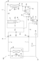
- FIG. 1 is a diagram showing an example of an overall configuration of a refrigeration device 100 according to a first embodiment.
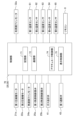
- FIG. 2 is a block diagram of a control unit 70 according to the first embodiment.
- FIG. 4 is a Mollier diagram during two-stage compression operation in the first embodiment.
- FIG. 4 is a Mollier diagram of the first embodiment during single-stage compression/venting operation.
- FIG. 11 is a Mollier diagram during single-stage compression operation in the second embodiment.
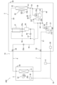
- FIG. 13 is a diagram showing an example of an overall configuration of a refrigeration device 200 according to a third embodiment.
- FIG. 13 is a block diagram of a control unit 70 according to a third embodiment.
- FIG. 13 is a diagram showing an example of an overall configuration of a refrigeration device 300 according to a modified example B.
- FIG. 13 is a Mollier diagram of the modified example B during single-stage compression/venting operation.
- the refrigeration apparatus 100 includes a heat source unit 2, a utilization unit 3, a liquid side refrigerant communication pipe 6, a gas side refrigerant communication pipe 7, a remote control 8, and a control unit 70.
- the heat source unit 2 and the utilization unit 3 are connected via the liquid side refrigerant communication pipe 6 and the gas side refrigerant communication pipe 7 to configure a refrigerant circuit 10 in which the refrigerant circulates.
- the refrigeration system 100 performs a vapor compression refrigeration cycle in which the refrigerant sealed in the refrigerant circuit 10 is compressed, condensed, depressurized, evaporated, and then compressed again.
- the refrigeration system 100 cools the air in the target space by the evaporation of the refrigerant circulating through the refrigeration cycle.
- the refrigeration system 100 is attached to, for example, a shipping container, and cools the air in the target space inside the container.
- the refrigeration device 100 may include multiple utilization units 3.
- the refrigerant circuit 10 is formed by connecting multiple utilization units 3 in parallel to one heat source unit 2.
- the refrigerant sealed in the refrigerant circuit 10 is carbon dioxide (R744).
- Carbon dioxide is a non-flammable natural refrigerant with a smaller global warming potential (GWP) than fluorine-containing refrigerants.
- GWP global warming potential
- the high-pressure refrigerant in the refrigeration cycle is in a supercritical state, where its pressure is greater than the critical pressure.
- the heat source unit 2 is installed in a space outside the target space.
- the heat source unit 2 is installed, for example, outdoors.
- the heat source unit 2 has a first compressor 21, a first accumulator 21b, a second compressor 22, a second accumulator 22b, a heat source side heat exchanger 23, a heat source side fan 24, a first heat source side expansion valve 25a, a second heat source side expansion valve 25b, a gas-liquid separator 26, an intermediate heat exchanger 27, a liquid side shutoff valve 28, a gas side shutoff valve 29, a gas vent valve 41, a first shutoff valve 43, and a second shutoff valve 44.
- the heat source unit 2 has a first pipe 51 to a sixth pipe 56 and a bypass pipe 59, which are pipes through which the refrigerant circulating in the refrigerant circuit 10 flows.
- the first pipe 51 connects the gas side shutoff valve 29 and the suction side of the first compressor 21.
- the second pipe 52 connects the discharge side of the first compressor 21 and the suction side of the second compressor 22.
- the third pipe 53 connects the discharge side of the second compressor 22 and the inlet side of the heat source side heat exchanger 23.
- the fourth pipe 54 connects the outlet side of the heat source side heat exchanger 23 and the inlet side of the gas-liquid separator 26.
- the fifth pipe 55 connects the liquid outlet side of the gas-liquid separator 26 and the liquid side shutoff valve 28.
- the sixth pipe 56 connects the gas outlet side of the gas-liquid separator 26 and the second pipe 52.
- the bypass pipe 59 connects the second pipe 52 and the third pipe 53.
- the first compressor 21 and the second compressor 22 constitute the compression mechanism of the refrigeration device 100, and compress the low-pressure refrigerant in the refrigeration cycle until it becomes a high-pressure refrigerant.
- the low-pressure refrigerant in the refrigeration cycle is compressed by the first compressor 21 to become an intermediate-pressure refrigerant.
- the intermediate-pressure refrigerant is compressed by the second compressor 22 to become a high-pressure refrigerant.
- the intermediate pressure in the refrigeration cycle is a pressure between the low pressure and the high pressure.
- the intermediate-pressure refrigerant in the refrigeration cycle is in a state where its pressure is lower than the critical pressure.
- the first compressor 21 and the second compressor 22 have a sealed structure in which a variable-volume compression element such as a rotary type or a scroll type is rotated and driven by the first compressor motor 21a and the second compressor motor 22a, respectively.
- the first compressor motor 21a and the second compressor motor 22a can control the operating frequency (the rotation speed of the first compressor 21 and the second compressor 22) by an inverter.
- the first accumulator 21b is provided in the first pipe 51.
- the second accumulator 22b is provided in the second pipe 52.
- the first accumulator 21b and the second accumulator 22b are refrigerant containers capable of temporarily storing the excess refrigerant in the refrigerant circuit 10 as liquid refrigerant.
- the heat source side heat exchanger 23 is a gas cooler that functions as a radiator (condenser) for the high-pressure refrigerant in the refrigeration cycle.
- the heat source side fan 24 supplies air outside the target space (external air, etc.) to the heat source side heat exchanger 23, exchanges heat with the refrigerant in the heat source side heat exchanger 23, and then generates an air flow for discharging the air outside the heat source unit 2.
- the heat source side fan 24 is driven to rotate by the heat source side fan motor 24a.
- the first heat source side expansion valve 25a is provided on the fourth pipe 54.
- the second heat source side expansion valve 25b is provided on the fifth pipe 55.
- the first heat source side expansion valve 25a and the second heat source side expansion valve 25b constitute the expansion mechanism of the refrigeration device 100, and reduce the pressure of the high-pressure refrigerant in the refrigeration cycle to a low-pressure refrigerant.
- the high-pressure refrigerant in the refrigeration cycle is reduced in pressure by the first heat source side expansion valve 25a to an intermediate-pressure refrigerant.
- the intermediate-pressure refrigerant is reduced in pressure by the second heat source side expansion valve 25b to a low-pressure refrigerant.
- the first heat source side expansion valve 25a and the second heat source side expansion valve 25b are electric expansion valves whose opening can be adjusted by control of the control unit 70.
- the gas-liquid separator 26 is a container for separating the refrigerant that has been reduced in pressure by the first heat source side expansion valve 25a and is in a two-phase gas-liquid state into liquid refrigerant and gas refrigerant.
- the two-phase gas-liquid refrigerant that has passed through the first heat source side expansion valve 25a flows into the gas-liquid separator 26 from the inlet side of the gas-liquid separator 26.
- the gas refrigerant separated in the gas-liquid separator 26 flows out from the gas outlet side of the gas-liquid separator 26.
- the liquid refrigerant separated in the gas-liquid separator 26 flows out from the liquid outlet side of the gas-liquid separator 26.
- the intermediate heat exchanger 27 exchanges heat between the refrigerant that has had heat dissipated in the heat source side heat exchanger 23 and before it is depressurized by the first heat source side expansion valve 25a, and the gas refrigerant that flows out from the gas outlet side of the gas-liquid separator 26.
- the refrigerant that has not yet been depressurized by the first heat source side expansion valve 25a dissipates heat through heat exchange in the intermediate heat exchanger 27.
- the gas refrigerant that flows out from the gas outlet side of the gas-liquid separator 26 is heated through heat exchange in the intermediate heat exchanger 27.
- the liquid side shutoff valve 28 is a manual valve located at the connection with the liquid side refrigerant connection pipe 6.
- the gas side shutoff valve 29 is a manual valve located at the connection with the gas side refrigerant connection pipe 7.
- the gas vent valve 41 is provided in the sixth pipe 56.
- the gas vent valve 41 is provided between the gas-liquid separator 26 and the intermediate heat exchanger 27.
- the gas vent valve 41 adjusts the amount of gas refrigerant flowing through the sixth pipe 56.
- the gas vent valve 41 is an electric expansion valve whose opening can be adjusted by control of the control unit 70.
- the first shutoff valve 43 is provided in the second pipe 52. As shown in FIG. 1, in the second pipe 52, a connection part with the bypass pipe 59, the first shutoff valve 43, and a connection part with the sixth pipe 56 are provided in that order from the discharge side of the first compressor 21 toward the suction side of the second compressor 22.
- the first shutoff valve 43 is an electric expansion valve whose opening can be adjusted by control of the control unit 70. When closed, the first shutoff valve 43 shuts off the flow of refrigerant from the discharge side of the first compressor 21 toward the suction side of the second compressor 22.
- the second shutoff valve 44 is provided in the bypass pipe 59.
- the second shutoff valve 44 is a check valve.
- the second shutoff valve 44 allows the flow of refrigerant from the second pipe 52 to the third pipe 53.
- the second shutoff valve 44 shuts off the flow of refrigerant from the third pipe 53 to the second pipe 52.
- the second shutoff valve 44 may be an electric expansion valve whose opening can be adjusted by control of the control unit 70.
- the heat source unit 2 has a heat source unit control unit 20 that controls the operation of each component that constitutes the heat source unit 2.
- the heat source unit control unit 20 constitutes the control unit 70.
- the heat source unit control unit 20 is, for example, a microcomputer including a CPU and memory.
- the heat source unit control unit 20 is connected to the utilization unit control unit 30 of the utilization unit 3 via a communication line, and transmits and receives control signals, etc.
- the heat source unit 2 further includes a first temperature sensor 61 to a fifth temperature sensor 65.
- the first temperature sensor 61 is attached to the third pipe 53.
- the first temperature sensor 61 is attached, for example, near the inlet of the heat source side heat exchanger 23.
- the first temperature sensor 61 measures a first temperature, which is the temperature of the refrigerant at the inlet of the heat source side heat exchanger 23.
- the first temperature is substantially equal to the temperature of the refrigerant before it flows into the heat source side heat exchanger 23 and is heat exchanged in the heat source side heat exchanger 23.
- the second temperature sensor 62 is installed outdoors.
- the second temperature sensor 62 is attached, for example, to the outer surface of the casing of the heat source unit 2.
- the second temperature sensor 62 measures a second temperature, which is the temperature of the air undergoing heat exchange with the refrigerant in the heat source side heat exchanger 23.
- the second temperature is substantially equal to the outside air temperature.
- the third temperature sensor 63 is installed in the target space.
- the third temperature sensor 63 is attached, for example, to the outer surface of the casing of the utilization unit 3.
- the third temperature sensor 63 measures a third temperature, which is the temperature of the target space in which the utilization unit 3 is installed.
- the fourth temperature sensor 64 is attached to the first pipe 51.
- the fourth temperature sensor 64 is attached, for example, near the suction side of the first compressor 21.
- the fourth temperature sensor 64 measures a fourth temperature, which is the temperature of the refrigerant sucked into the first compressor 21.
- the fourth temperature is substantially equal to the evaporation temperature of the refrigerant.
- the fifth temperature sensor 65 is attached to the second pipe 52.
- the fifth temperature sensor 65 is attached, for example, near the discharge side of the first compressor 21.
- the fifth temperature sensor 65 measures a fifth temperature, which is the temperature of the refrigerant discharged from the first compressor 21.
- the utilization unit 3 is installed in the target space. As shown in FIG. 1 , the utilization unit 3 has a utilization side heat exchanger 31 and a utilization side fan 32.
- the user side heat exchanger 31 functions as a heat absorber (evaporator) for low pressure refrigerant in the refrigeration cycle.
- the piping extending from the inlet side of the user side heat exchanger 31 is connected to the liquid side refrigerant connection piping 6.
- the piping extending from the outlet side of the user side heat exchanger 31 is connected to the gas side refrigerant connection piping 7.
- the utilization side fan 32 supplies air from the target space to the utilization side heat exchanger 31, where it exchanges heat with the refrigerant, and then generates an air flow for discharging the air into the target space.
- the utilization side fan 32 is driven to rotate by the utilization side fan motor 32a.
- the utilization unit 3 has a utilization unit control unit 30 that controls the operation of each component that constitutes the utilization unit 3.
- the utilization unit control unit 30 constitutes the control unit 70.
- the utilization unit control unit 30 is, for example, a microcomputer that includes a CPU, memory, etc.
- the utilization unit control unit 30 is connected to the heat source unit control unit 20 of the heat source unit 2 via a communication line, and transmits and receives control signals, etc.
- the remote control 8 functions as an input device for a user of the refrigeration apparatus 100 to input various instructions to the refrigeration apparatus 100. For example, the user operates the remote control 8 to adjust the set temperature and set humidity of the target space.
- the remote control 8 also functions as a display device for displaying the operating state of the refrigeration apparatus 100 and predetermined notification information.
- the remote control 8 is connected to the heat source unit control unit 20 and the utilization unit control unit 30 via communication lines, and transmits and receives signals to and from each other.
- Control Unit 70 In the refrigeration device 100, the heat source unit control unit 20 and the utilization unit control unit 30 are connected via a communication line to configure a control unit 70, which is hardware that controls the operation of the refrigeration device 100.
- the control by the control unit 70 is realized by the heat source unit control unit 20 and the utilization unit control unit 30 operating together.
- the control unit 70 is electrically connected to the actuators included in the heat source unit 2.
- the actuators included in the heat source unit 2 are the first compressor motor 21a, the second compressor motor 22a, the heat source side fan motor 24a, the first heat source side expansion valve 25a, the second heat source side expansion valve 25b, the gas vent valve 41, and the first shutoff valve 43.
- the control unit 70 is also electrically connected to the first temperature sensor 61 to the fifth temperature sensor 65, the remote control 8, and the actuators included in the utilization unit 3.
- the actuator included in the utilization unit 3 is the utilization side fan motor 32a.
- control unit 70 has a memory unit 71, a communication unit 72, an actuator control unit 74, and a display control unit 75. Each of these elements realizes a specific function of the control unit 70.
- the control unit 70 executes these functions by executing control programs stored in the ROM, RAM, flash memory, etc.
- the memory unit 71 stores predetermined information in a predetermined memory area upon request from other elements of the control unit 70.
- the predetermined information is, for example, the results of calculations performed by the control unit 70 and commands input to the remote control 8.
- the communication unit 72 functions as a communication interface for transmitting and receiving signals to and from each device connected to the control unit 70. Upon receiving a request from the actuator control unit 74, the communication unit 72 transmits a specified signal to a specified actuator. The communication unit 72 receives signals output from the remote control 8, etc., and requests the memory unit 71 to store the signals in a specified memory area. The communication unit 72 also receives the temperatures measured by the first temperature sensor 61 to the fifth temperature sensor 65 from the first temperature sensor 61 to the fifth temperature sensor 65.
- the actuator control unit 74 controls the operation of each actuator included in the refrigeration device 100 based on a control program. Specifically, the actuator control unit 74 has a function of controlling in real time the rotation speed of the first compressor 21, the rotation speed of the second compressor 22, the rotation speed of the heat source side fan 24, the opening degree of the first heat source side expansion valve 25a, the opening degree of the second heat source side expansion valve 25b, the rotation speed of the utilization side fan 32, the opening degree of the gas vent valve 41, and the opening degree of the first shutoff valve 43.
- the display control unit 75 is a functional unit that controls the operation of the remote control 8 as a display device.
- the display control unit 75 causes the remote control 8 to output predetermined information in order to notify the user of information related to the operating state and status of the refrigeration device 100.
- the display control unit 75 causes the display of the remote control 8 to display the set temperature, etc.
- the refrigerant circuit 10 is in one of a first state and a second state.
- the gas vent valve 41 is closed and the first shutoff valve 43 is open.
- the gas vent valve 41 is open and the first shutoff valve 43 is closed.
- FIG. 3 is a Mollier diagram when the refrigerant circuit 10 is in the first state.
- the first state is a state in which the refrigeration device 100 performs two-stage compression operation.
- the two-stage compression operation is an operation in which the gas refrigerant that has been heat exchanged in the user-side heat exchanger 31 is compressed by the first compressor 21 and the second compressor 22.
- the low-pressure refrigerant in the refrigeration cycle is compressed in sequence by the first compressor 21 on the low-stage side and the second compressor 22 on the high-stage side to become the high-pressure refrigerant in the refrigeration cycle.
- the first compressor 21 draws in and compresses the low-pressure refrigerant flowing through the first pipe 51, and discharges the intermediate-pressure refrigerant to the second pipe 52.
- the intermediate-pressure refrigerant discharged to the second pipe 52 passes through the first shutoff valve 43.
- the second compressor 22 draws in and compresses the intermediate-pressure refrigerant flowing through the second pipe 52, and discharges the high-pressure refrigerant to the third pipe 53.
- Figure 4 is a Mollier diagram when the refrigerant circuit 10 is in the second state.
- the second state is a state in which the refrigeration device 100 performs single-stage compression/degassing operation.
- single-stage compression/degassing operation single-stage compression operation and degassing operation are performed.
- the single-stage compression operation is an operation in which the gas refrigerant that has been heat exchanged in the user-side heat exchanger 31 is compressed by the first compressor 21.
- the degassing operation is an operation in which the gas refrigerant separated in the gas-liquid separator 26 is compressed by the second compressor 22.
- the low-pressure refrigerant in the refrigeration cycle is compressed by the first compressor 21 to become the high-pressure refrigerant in the refrigeration cycle.
- the first compressor 21 sucks in and compresses the low-pressure refrigerant flowing through the first pipe 51, and discharges the high-pressure refrigerant to the second pipe 52.
- the high-pressure refrigerant discharged to the second pipe 52 cannot pass through the first shutoff valve 43 and flows into the bypass pipe 59.
- the high-pressure refrigerant that flows into the bypass pipe 59 passes through the second shutoff valve 44 and flows into the third pipe 53.
- the intermediate-pressure refrigerant in the refrigeration cycle is compressed by the second compressor 22 to become high-pressure refrigerant in the refrigeration cycle.
- the second compressor 22 sucks in and compresses the intermediate-pressure gas refrigerant that has flowed from the gas-liquid separator 26 through the sixth pipe 56 into the second pipe 52, and discharges the high-pressure refrigerant into the third pipe 53.
- the high-pressure refrigerant discharged from the first compressor 21 by single-stage compression operation and the high-pressure refrigerant discharged from the second compressor 22 by degassing operation join in the third pipe 53.
- the refrigerant that joins in the third pipe 53 flows into the heat source side heat exchanger 23.
- the refrigerant that has released heat in the heat source side heat exchanger 23 is depressurized by the first heat source side expansion valve 25a to become an intermediate pressure refrigerant (P5 ⁇ P6).
- the refrigerant that has been depressurized by the first heat source side expansion valve 25a to become a gas-liquid two-phase state flows into the gas-liquid separator 26 and is separated into liquid refrigerant and gas refrigerant (P6 ⁇ P7, P8).
- the liquid refrigerant separated in the gas-liquid separator 26 is further depressurized by the second heat source side expansion valve 25b to become a low pressure refrigerant (P7 ⁇ P9).
- the liquid refrigerant depressurized by the second heat source side expansion valve 25b passes through the liquid side stop valve 28 and the liquid side refrigerant connection pipe 6 to flow into the utilization unit 3 and into the utilization side heat exchanger 31.
- the low pressure liquid refrigerant that flows into the utilization side heat exchanger 31 exchanges heat with the air in the target space in which the utilization unit 3 is installed, absorbs heat, and becomes a gas refrigerant (P9 ⁇ P1).
- the refrigerant that absorbs heat in the user side heat exchanger 31 passes through the gas side refrigerant connection pipe 7 and flows into the heat source unit 2 from the gas side shutoff valve 29.
- the low-pressure refrigerant that flows into the heat source unit 2 is sucked into the first compressor 21.
- the refrigerant that has dissipated heat in the heat source side heat exchanger 23 exchanges heat with the gas refrigerant separated in the gas-liquid separator 26 in the intermediate heat exchanger 27 and further dissipates heat (P5 ⁇ P6). After that, the refrigerant that has dissipated heat in the intermediate heat exchanger 27 is depressurized by the first heat source side expansion valve 25a to become an intermediate pressure refrigerant (P6 ⁇ P7).
- the refrigerant that has been depressurized by the first heat source side expansion valve 25a to become a gas-liquid two-phase state flows into the gas-liquid separator 26 and is separated into liquid refrigerant and gas refrigerant (P7 ⁇ P8, P9).
- the liquid refrigerant separated in the gas-liquid separator 26 is further depressurized by the second heat source side expansion valve 25b to become a low pressure refrigerant (P8 ⁇ P10).
- the liquid refrigerant depressurized by the second heat source side expansion valve 25b flows into the utilization unit 3 through the liquid side shutoff valve 28 and the liquid side refrigerant connection pipe 6, and then flows into the utilization side heat exchanger 31.
- the low-pressure liquid refrigerant that flows into the user-side heat exchanger 31 exchanges heat with the air in the target space in which the user unit 3 is installed, absorbing heat and becoming a gas refrigerant (P10 ⁇ P1).
- the refrigerant that absorbed heat in the user-side heat exchanger 31 passes through the gas-side refrigerant connection pipe 7 and flows into the heat source unit 2 from the gas-side shutoff valve 29.
- the low-pressure refrigerant that flows into the heat source unit 2 is sucked into the first compressor 21.
- the gas refrigerant separated in the gas-liquid separator 26 flows through the sixth pipe 56 and is slightly depressurized when passing through the gas vent valve 41 (P9 ⁇ P11).
- the depressurized gas refrigerant is heated in the intermediate heat exchanger 27 by heat exchange with the refrigerant before being depressurized by the first heat source side expansion valve 25a, and is sucked into the second compressor 22 (P11 ⁇ P3).
- control unit 70 controls the state of the refrigerant circuit 10 in real time based on at least one of the first temperature to fifth temperature obtained from the first temperature sensor 61 to fifth temperature sensor 65.
- the refrigerant circuit 10 is in the second state, and the refrigeration device 100 performs single-stage compression/venting operation.
- pull-down operation is an operation in which the difference between the temperature of the target space of the refrigeration device 100 and the outside air temperature is small, and high refrigeration capacity is required to lower the temperature of the target space to the set temperature of the target space.
- pull-down operation begins, for example, the difference between the temperature of the target space and the outside air temperature is zero.
- the control unit 70 switches the refrigerant circuit 10 from the second state to the first state if a predetermined first condition is satisfied. As a result, the refrigeration device 100 stops the single-stage compression/gas venting operation and starts the two-stage compression operation.
- the control unit 70 switches the refrigerant circuit 10 from the second state to the first state by closing the gas venting valve 41 and opening the first shutoff valve 43.
- the first condition is satisfied when the temperature of the refrigerant sucked into the first compressor 21 drops to a first value and the temperature of the refrigerant discharged from the first compressor 21 rises to a second value.
- the control unit 70 uses the fourth temperature measured by the fourth temperature sensor 64 as the temperature of the refrigerant sucked into the first compressor 21.
- the control unit 70 uses the fifth temperature measured by the fifth temperature sensor 65 as the temperature of the refrigerant discharged from the first compressor 21.
- the control unit 70 switches the refrigerant circuit 10 from the first state to the second state when a predetermined second condition is satisfied.
- the refrigeration device 100 stops the two-stage compression operation and starts the single-stage compression/gas venting operation.
- the control unit 70 switches the refrigerant circuit 10 from the first state to the second state by opening the gas vent valve 41 and closing the first shutoff valve 43.
- the second condition is satisfied when the temperature of the refrigerant sucked into the first compressor 21 rises to a third value or when the rotation speed of the first compressor 21 falls below the rotation speed of the second compressor 22.
- the control unit 70 uses the fourth temperature measured by the fourth temperature sensor 64 as the temperature of the refrigerant sucked into the first compressor 21.
- the control unit 70 obtains the rotation speeds of the first compressor 21 and the second compressor 22 from the actuator control unit 74.
- the desired compression ratio of the low-stage compressor is reduced during pull-down operation in which the evaporation temperature of the refrigerant is high, and the refrigeration capacity may be insufficient.
- the refrigeration system 100 of this embodiment can perform two-stage compression operation and single-stage compression/venting operation.
- the control unit 70 of the refrigeration system 100 can switch between a first state in which two-stage compression operation is performed and a second state in which single-stage compression/venting operation is performed by controlling the venting valve 41 and the first shutoff valve 43.
- the refrigeration system 100 When the refrigeration system 100 is in pull-down operation, a high refrigeration capacity is required, so the pressure of the refrigerant on the high-pressure side of the refrigeration cycle needs to be kept high.
- the refrigeration system 100 can ensure a sufficient compression ratio of the first compressor 21, as shown in FIG. 4. Therefore, the refrigeration system 100 can maintain a high pressure of the refrigerant on the high-pressure side of the refrigeration cycle during pull-down operation.
- the refrigeration system 100 can suppress a decrease in refrigeration capacity caused by an inability to ensure a sufficient compression ratio of the first compressor 21 on the low stage side during pull-down operation.
- the control unit 70 switches from the second state in which the refrigeration apparatus 100 performs single-stage compression/gas venting operation to a first state in which the refrigeration apparatus 100 performs two-stage compression operation.
- the control unit 70 determines that the above-mentioned first condition is satisfied, it switches from the second state to the first state.
- the first condition is satisfied when the temperature of the refrigerant sucked into the first compressor 21 (evaporation temperature of the refrigerant) drops to a predetermined value and the temperature of the refrigerant discharged from the first compressor 21 rises to a predetermined value.
- the control unit 70 may use the fourth temperature measured by the fourth temperature sensor 64 as the temperature of the refrigerant sucked into the first compressor 21.
- the control unit 70 may use the fifth temperature measured by the fifth temperature sensor 65 as the temperature of the refrigerant discharged from the first compressor 21. In this case, when the control unit 70 detects that the first condition is satisfied during single-stage compression/venting operation, it controls the venting valve 41 and the first shutoff valve 43 to switch from the second state to the first state. This causes the refrigeration device 100 to stop the single-stage compression/venting operation and start the two-stage compression operation.
- the refrigeration system 100 When the refrigeration system 100 performs single-stage compression/venting operation during pull-down operation, the evaporation temperature of the refrigerant drops, the compression ratio of the first compressor 21 increases, and the temperature of the refrigerant on the high-pressure side of the refrigeration cycle (the temperature of the refrigerant discharged from the first compressor 21) rises. As a result, the load on the first compressor 21 increases, and there is a risk of the reliability of the first compressor 21 decreasing.
- the refrigeration system 100 determines that the compression ratio of the first compressor 21 has become sufficiently large and the temperature of the refrigerant discharged from the first compressor 21 has become sufficiently high during single-stage compression/venting operation, it stops the single-stage compression/venting operation and starts two-stage compression operation.
- the refrigeration system 100 can reduce the load on the low-stage first compressor 21 and suppress a decrease in the reliability of the first compressor 21. This allows the refrigeration system 100 to effectively utilize the first compressor 21, making it possible to employ a first compressor 21 with a small capacity, thereby reducing costs and power consumption.
- the control unit 70 switches from the first state in which the refrigeration apparatus 100 performs two-stage compression operation to a second state in which the refrigeration apparatus 100 performs single-stage compression/gas venting operation.
- the control unit 70 determines that the above-mentioned second condition is satisfied, it switches from the first state to the second state.
- the second condition is satisfied when the temperature of the refrigerant sucked into the first compressor 21 (evaporation temperature of the refrigerant) rises to a predetermined value or the rotation speed of the first compressor 21 falls below the rotation speed of the second compressor 22.
- the control unit 70 may use the fourth temperature measured by the fourth temperature sensor 64 as the temperature of the refrigerant sucked into the first compressor 21. In this case, when the control unit 70 detects that the second condition is satisfied during two-stage compression operation, it controls the gas vent valve 41 and the first shutoff valve 43 to switch from the first state to the second state. This causes the refrigeration device 100 to stop the two-stage compression operation and start the single-stage compression/gas vent operation.
- the temperature of the refrigerant sucked into the first compressor 21 may gradually rise.
- the pressure of the refrigerant in the gas-liquid separator 26 pressure of the intermediate pressure refrigerant
- the critical pressure of the refrigerant 7.38 MPa
- it needs to be kept at a maximum of about 7 MPa. Therefore, if the evaporation temperature of the refrigerant rises during two-stage compression operation, there is a risk that the compression ratio of the first compressor 21 will decrease.
- the refrigeration system 100 determines that the temperature of the refrigerant sucked into the first compressor 21 has become sufficiently high during two-stage compression operation, it stops the two-stage compression operation and starts single-stage compression/venting operation.
- the refrigeration system 100 can ensure a sufficient compression ratio of the first compressor 21 on the low stage side, thereby preventing a decrease in refrigeration capacity.
- the rotation speed of the first compressor 21 may fall below the rotation speed of the second compressor 22, causing the second compressor 22 to be overloaded.
- the load on the second compressor 22 can be reduced by having the second compressor 22 perform a degassing operation.
- the refrigeration device 100 can reduce the load on the second compressor 22 on the high stage side, and suppress a decrease in the reliability of the second compressor 22. As a result, the refrigeration device 100 can effectively utilize the second compressor 22, and can adopt a second compressor 22 with a smaller capacity, thereby reducing costs and power consumption.
- the refrigeration system 100 uses the intermediate heat exchanger 27 to cool the refrigerant at the outlet of the heat source side heat exchanger 23 by heat exchange with the gas refrigerant separated in the gas-liquid separator 26. This reduces the dryness of the refrigerant that has been decompressed after passing through the first heat source side expansion valve 25a.
- the refrigeration system 100 can prevent a shortage of refrigerant being sucked into the first compressor 21 on the low stage side.
- the refrigeration device 100 can determine whether to perform a single-stage compression/degassing operation or a two-stage compression operation according to the outside air temperature and the temperature of the target space.
- the control unit 70 may use the second temperature measured by the second temperature sensor 62 as the outside air temperature.
- the control unit 70 may use the third temperature measured by the third temperature sensor 63 as the temperature of the target space.
- the control unit 70 starts the single-stage compression/degassing operation as the pull-down operation when the second temperature is equal to or higher than a predetermined value and the difference between the second temperature and the third temperature is equal to or lower than a predetermined value at the start-up of the refrigeration device 100.
- the control unit 70 starts the two-stage compression operation for the pull-down operation when the second temperature is less than a predetermined value or the difference between the second temperature and the third temperature is greater than a predetermined value at the start-up of the refrigeration device 100.
- the refrigeration device 100 can suppress a decrease in refrigeration capacity by performing pull-down operation while taking into consideration the balance between the load on the first compressor 21 on the low-stage side and the load on the second compressor 22 on the high-stage side.
- the refrigeration device 100 of this embodiment has the configuration shown in Fig. 1, similar to the first embodiment.
- the control unit 70 of the refrigeration device 100 of this embodiment has the configuration shown in Fig. 2, similar to the first embodiment.
- the refrigerant circuit 10 is in one of a first state, a second state, and a third state.
- the refrigeration device 100 performs a two-stage compression operation shown in Fig. 3.
- the refrigeration device 100 performs a single-stage compression/venting operation shown in Fig. 4.
- FIG. 5 is a Mollier diagram when the refrigerant circuit 10 is in the third state.
- the saturated liquid line L1, the dry saturated vapor line L2, and the critical point CP of the refrigerant are depicted.
- the critical point CP is the high-pressure side end point of the saturated liquid line L1 and the dry saturated vapor line L2.
- the third state is a state in which the refrigeration device 100 performs single-stage compression operation. In the third state, no degassing operation is performed. In the third state, the degassing valve 41 and the first shutoff valve 43 are closed.
- the low-pressure refrigerant flowing through the refrigerant circuit 10 is compressed in the first compressor 21 to become high-pressure refrigerant (P1 ⁇ P2).
- the high-pressure refrigerant discharged from the first compressor 21 flows into the heat source side heat exchanger 23.
- the high-pressure refrigerant that flows into the heat source side heat exchanger 23 exchanges heat with the outside air and dissipates heat (P2 ⁇ P3).
- the refrigerant that has released heat in the heat source side heat exchanger 23 is depressurized by the first heat source side expansion valve 25a to become an intermediate pressure refrigerant (P3 ⁇ P4).
- the refrigerant that has been depressurized by the first heat source side expansion valve 25a to become a gas-liquid two-phase state flows into the gas-liquid separator 26 and is separated into liquid refrigerant and gas refrigerant (P4 ⁇ P5, P6).
- the liquid refrigerant separated in the gas-liquid separator 26 is further depressurized by the second heat source side expansion valve 25b to become a low pressure refrigerant (P5 ⁇ P7).
- the liquid refrigerant depressurized by the second heat source side expansion valve 25b passes through the liquid side stop valve 28 and the liquid side refrigerant connection pipe 6 to flow into the utilization unit 3 and into the utilization side heat exchanger 31.
- the low pressure liquid refrigerant that flows into the utilization side heat exchanger 31 exchanges heat with the air in the target space in which the utilization unit 3 is installed, absorbs heat, and becomes a gas refrigerant (P7 ⁇ P1).
- the refrigerant that absorbs heat in the user side heat exchanger 31 passes through the gas side refrigerant connection pipe 7 and flows into the heat source unit 2 from the gas side shutoff valve 29.
- the low-pressure refrigerant that flows into the heat source unit 2 is sucked into the first compressor 21.
- the control unit 70 switches the state of the refrigerant circuit 10 in the order of the third state, the second state, and the first state when the first compressor 21 and the second compressor 22 are started up. Specifically, the control unit 70 controls the gas vent valve 41 and the first shutoff valve 43 so that the refrigeration device 100 performs single-stage compression operation, single-stage compression/gas vent operation, and two-stage compression operation in this order when the refrigeration device 100 is started up.
- the control unit 70 controls the gas vent valve 41 to open, thereby stopping the single-stage compression operation and starting the single-stage compression/gas vent operation.
- the refrigeration device 100 Immediately after the refrigeration device 100 is started, the amount of refrigerant on the high-pressure side of the refrigeration cycle is small, and therefore the amount of gas refrigerant in the gas-liquid separator 26 is small. Therefore, the refrigeration device 100 does not perform degassing operation when the amount of refrigerant on the high-pressure side of the refrigeration cycle is small at start-up, but starts degassing operation when a predetermined time has passed since start-up and the amount of refrigerant on the high-pressure side of the refrigeration cycle has increased to a predetermined amount. As a result, the refrigeration device 100 can reduce the load on the second compressor 22 caused by the degassing operation and suppress a decrease in refrigeration capacity.
- the heat source unit 2 of the refrigeration system 200 is the heat source unit 2 of the refrigeration system 100 of the first embodiment, with the addition of a seventh pipe 57, a liquid injection valve 42, an oil return pipe 58, and an oil separator 60.
- the seventh pipe 57 is a pipe through which the refrigerant circulating in the refrigerant circuit 10 flows.
- the seventh pipe 57 connects the fifth pipe 55 and the sixth pipe 56.
- One end of the seventh pipe 57 is connected to the fifth pipe 55 between the gas-liquid separator 26 and the second heat source side expansion valve 25b.
- the other end of the seventh pipe 57 is connected to the sixth pipe 56 between the connection with the second pipe 52 and the intermediate heat exchanger 27.
- the liquid injection valve 42 is provided in the seventh pipe 57.
- the liquid injection valve 42 adjusts the amount of liquid refrigerant flowing through the seventh pipe 57.
- the liquid injection valve 42 is an electric expansion valve whose opening can be adjusted by control of the control unit 70.
- the oil return pipe 58 is a pipe through which the refrigerant circulating in the refrigerant circuit 10 flows.
- the oil return pipe 58 connects the second pipe 52 and the third pipe 53.
- One end of the oil return pipe 58 is connected to the second pipe 52 between the connection with the sixth pipe 56 and the second compressor 22.
- the other end of the oil return pipe 58 is connected to the third pipe 53 between the connection with the bypass pipe 59 and the heat source side heat exchanger 23.
- the oil separator 60 is provided in the oil return pipe 58.
- the oil separator 60 separates the refrigeration oil from the mixture of the refrigerant and the refrigeration oil.
- the actuator control unit 74 of the control unit 70 has the function of controlling in real time the rotation speed of the first compressor 21, the rotation speed of the second compressor 22, the rotation speed of the heat source side fan 24, the opening degree of the first heat source side expansion valve 25a, the opening degree of the second heat source side expansion valve 25b, the rotation speed of the utilization side fan 32, the opening degree of the gas vent valve 41, the opening degree of the liquid injection valve 42, and the opening degree of the first shutoff valve 43.
- the refrigeration oil mixed with the refrigerant discharged from the first compressor 21 and the second compressor 22 is returned to the suction side of the second compressor 22.
- Control of refrigeration device 200 The control unit 70 of the refrigeration device 200 performs the same control as the control unit 70 of the first embodiment. In addition, the control unit 70 controls the opening degree of the liquid injection valve 42 during operation of the refrigeration device 200 to adjust the amount of the mixture of the refrigerant and the refrigerating machine oil flowing through the seventh pipe 57.
- the refrigeration device 200 can return the refrigeration oil flowing through the refrigerant circuit 10 to the suction side of the second compressor 22. Therefore, the refrigeration device 200 can suppress a shortage of refrigeration oil in the second compressor 22.
- the refrigeration apparatus 100, 200 of the first to third embodiments may further perform a venting operation when the refrigerant circuit 10 is in the first state.
- the refrigeration apparatus 100, 200 may perform both the two-stage compression operation and the venting operation simultaneously.
- the control unit 70 opens both the vent valve 41 and the first shutoff valve 43 to perform both the two-stage compression operation and the venting operation simultaneously.
- the gas refrigerant separated in the gas-liquid separator 26 is heated in the intermediate heat exchanger 27 by heat exchange with the refrigerant at the outlet of the heat source side heat exchanger 23.
- the refrigerant heated in the intermediate heat exchanger 27 flows into the second pipe 52 and is mixed with the refrigerant before being sucked into the second compressor 22.
- the degree of superheat of the refrigerant sucked into the second compressor 22 increases, and the temperature of the refrigerant discharged from the second compressor 22 increases. Therefore, the refrigeration devices 100, 200 can increase the difference between the first temperature and the second temperature and maintain high performance of the heat source side heat exchanger 23.
- Modification B (2-1) Configuration of refrigeration device 300
- the refrigeration devices 100, 200 of the first to third embodiments do not need to include the gas-liquid separator 26.
- the refrigeration device 300 of this modification is the refrigeration device 100 of the first embodiment, but does not include the gas-liquid separator 26.
- the main differences between the refrigeration device 300 and the refrigeration device 100 of the first embodiment are the heat source unit 2 and the control unit 70.
- the heat source unit 2 has a first compressor 21, a first accumulator 21b, a second compressor 22, a second accumulator 22b, a heat source side heat exchanger 23, a heat source side fan 24, a second heat source side expansion valve 25b, a cooler 127, a liquid side shutoff valve 28, a gas side shutoff valve 29, a pressure reducing valve 141, a first shutoff valve 43, and a second shutoff valve 44.
- the heat source unit 2 has a first pipe 51 to a sixth pipe 56, which are pipes through which the refrigerant circulating in the refrigerant circuit 10 flows.
- the first pipe 51 to the third pipe 53 are the same as the first pipe 51 to the third pipe 53 in the first embodiment.
- One end of the fourth pipe 54 is connected to the outlet side of the heat source side heat exchanger 23.
- the other end of the fourth pipe 54 is connected to one end of the fifth pipe 55 and one end of the sixth pipe 56.
- the fifth pipe 55 connects the fourth pipe 54 to the liquid side shutoff valve 28.
- the sixth pipe 56 connects the fourth pipe 54 to the second pipe 52.
- the second heat source side expansion valve 25b is provided in the fifth pipe 55.
- the second heat source side expansion valve 25b constitutes the expansion mechanism of the refrigeration device 300, and reduces the pressure of the high-pressure refrigerant in the refrigeration cycle until it becomes a low-pressure refrigerant.
- the pressure reducing valve 141 is provided in the sixth pipe 56.
- the pressure reducing valve 141 reduces the pressure of the high-pressure refrigerant in the refrigeration cycle until it becomes an intermediate-pressure refrigerant.
- the pressure reducing valve 141 adjusts the amount of liquid refrigerant flowing through the sixth pipe 56.
- the pressure reducing valve 141 is an electric expansion valve whose opening can be adjusted under the control of the control unit 70.
- the cooler 127 exchanges heat between the refrigerant after heat dissipation in the heat source side heat exchanger 23 and pressure reduction by the pressure reducing valve 141, and the refrigerant after heat dissipation in the heat source side heat exchanger 23 and before pressure reduction by the second heat source side expansion valve 25b.
- the actuator control unit 74 of the control unit 70 has the function of controlling the rotation speed of the first compressor 21, the rotation speed of the second compressor 22, the rotation speed of the heat source side fan 24, the opening degree of the second heat source side expansion valve 25b, the rotation speed of the utilization side fan 32, the opening degree of the pressure reducing valve 141, and the opening degree of the first shutoff valve 43 in real time.
- the intermediate pressure refrigerant that has been depressurized by the pressure reducing valve 141 and heated by heat exchange in the cooler 127 flows through the sixth pipe 56 and the second pipe 52 and is sucked into the second compressor 22.
- the degassing operation performed by the refrigeration system 300 has the same effect as the degassing operation performed by the refrigeration systems 100 and 200 of the first to third embodiments.
- the refrigerant circuit 10 is in either a first state or a second state.
- the refrigeration system 300 performs a two-stage compression operation.
- the refrigeration system 300 performs a single-stage compression/venting operation.
- the pressure reducing valve 141 is closed and the first shutoff valve 43 is open.
- the pressure reducing valve 141 is open and the first shutoff valve 43 is closed.
- Figure 9 is a Mollier diagram when the refrigerant circuit 10 is in the second state.
- Figure 9 shows the saturated liquid line L1, dry saturated vapor line L2, and critical point CP of the refrigerant.
- the critical point CP is the high-pressure side end point of the saturated liquid line L1 and the dry saturated vapor line L2.
- the low-pressure refrigerant flowing through the refrigerant circuit 10 is compressed in the first compressor 21 to become high-pressure refrigerant (P1 ⁇ P2).
- the high-pressure refrigerant discharged from the first compressor 21 merges with the high-pressure refrigerant discharged from the second compressor 22 and flows into the heat source side heat exchanger 23.
- the high-pressure refrigerant that flows into the heat source side heat exchanger 23 exchanges heat with the outside air and dissipates heat (P2 ⁇ P3).
- the refrigerant that has released heat in the heat source side heat exchanger 23 flows through the fourth pipe 54, and then is divided into the fifth pipe 55 and the sixth pipe 56.
- the refrigerant flowing through the fifth pipe 55 is depressurized by the pressure reducing valve 141 and flows into the cooler 127 (P3 ⁇ P4).
- the refrigerant flowing through the sixth pipe 56 flows into the cooler 127 before being depressurized by the second heat source side expansion valve 25b.
- heat exchange is performed between the refrigerant that has been depressurized by the pressure reducing valve 141 and that flows through the fifth pipe 55, and the refrigerant that flows through the sixth pipe 56.
- the refrigerant flowing through the fifth pipe 55 is heated by the heat exchange (P4 ⁇ P5).
- the refrigerant flowing through the sixth pipe 56 is cooled by the heat exchange (P3 ⁇ P6).
- the refrigerant flowing through the sixth pipe 56 is cooled by the cooler 127, and then depressurized by the second heat source side expansion valve 25b to become a low-pressure refrigerant (P6 ⁇ P7).
- the liquid refrigerant depressurized by the second heat source side expansion valve 25b passes through the liquid side shutoff valve 28 and the liquid side refrigerant connection pipe 6 to flow into the utilization unit 3, and then flows into the utilization side heat exchanger 31.
- the low-pressure liquid refrigerant that flows into the utilization side heat exchanger 31 exchanges heat with the air in the target space in which the utilization unit 3 is installed, absorbs heat, and becomes a gas refrigerant (P7 ⁇ P1).
- the refrigerant that absorbs heat in the utilization side heat exchanger 31 passes through the gas side refrigerant connection pipe 7 and flows into the heat source unit 2 from the gas side shutoff valve 29.
- the low-pressure refrigerant that flows into the heat source unit 2 is sucked into the first compressor 21.
- the refrigerant flowing through the fifth pipe 55 is heated in the cooler 127, then flows through the second pipe 52 and is compressed in the second compressor 22 to become a high-pressure refrigerant (P5 ⁇ P8).
- the refrigerant compressed in the second compressor 22 merges with the refrigerant compressed in the first compressor 21 before flowing into the heat source side heat exchanger 23 (P8 ⁇ P2).
- the second embodiment and modification A are applicable to this modification.
- the oil return pipe 58 and oil separator 60 of the third embodiment are applicable to this modification.
- the refrigeration device 200 of the third embodiment, the modified example A, and the modified example B includes a seventh pipe 57 and an oil return pipe 58 for returning refrigeration oil from the discharge side to the suction side of the second compressor 22.
- the refrigeration device 200 may include only one of the seventh pipe 57 and the oil return pipe 58.
- the refrigeration devices 100 and 200 of the first to third embodiments, the modified examples A, and the modified examples C may not include the intermediate heat exchanger 27 .
- the first shutoff valve 43 and the second shutoff valve 44 may be any member capable of switching the state (first to third states) of the refrigerant circuit 10.
- the first shutoff valve 43 and the second shutoff valve 44 may be a three-way switching valve or a four-way switching valve.
Landscapes
- Engineering & Computer Science (AREA)
- Physics & Mathematics (AREA)
- Mechanical Engineering (AREA)
- Thermal Sciences (AREA)
- General Engineering & Computer Science (AREA)
- Compression-Type Refrigeration Machines With Reversible Cycles (AREA)
Priority Applications (2)
| Application Number | Priority Date | Filing Date | Title |
|---|---|---|---|
| EP24732841.2A EP4462039A4 (en) | 2023-03-31 | 2024-03-26 | COOLING DEVICE |
| CN202480023549.4A CN121039447A (zh) | 2023-03-31 | 2024-03-26 | 冷冻装置 |
Applications Claiming Priority (2)
| Application Number | Priority Date | Filing Date | Title |
|---|---|---|---|
| JP2023058646A JP7670996B2 (ja) | 2023-03-31 | 2023-03-31 | 冷凍装置 |
| JP2023-058646 | 2023-03-31 |
Publications (1)
| Publication Number | Publication Date |
|---|---|
| WO2024204176A1 true WO2024204176A1 (ja) | 2024-10-03 |
Family
ID=91828962
Family Applications (1)
| Application Number | Title | Priority Date | Filing Date |
|---|---|---|---|
| PCT/JP2024/011913 Ceased WO2024204176A1 (ja) | 2023-03-31 | 2024-03-26 | 冷凍装置 |
Country Status (4)
| Country | Link |
|---|---|
| EP (1) | EP4462039A4 (https=) |
| JP (2) | JP7670996B2 (https=) |
| CN (1) | CN121039447A (https=) |
| WO (1) | WO2024204176A1 (https=) |
Cited By (1)
| Publication number | Priority date | Publication date | Assignee | Title |
|---|---|---|---|---|
| US20240253426A1 (en) * | 2023-01-27 | 2024-08-01 | Ford Global Technologies, Llc | Dehumidification control strategy |
Citations (6)
| Publication number | Priority date | Publication date | Assignee | Title |
|---|---|---|---|---|
| JP2007010282A (ja) * | 2005-07-04 | 2007-01-18 | Hitachi Ltd | 二段圧縮式冷凍サイクル装置 |
| WO2010061624A1 (ja) * | 2008-11-28 | 2010-06-03 | サンデン株式会社 | 冷凍システム |
| JP2011149669A (ja) * | 2010-01-25 | 2011-08-04 | Daikin Industries Ltd | 空気調和装置 |
| JP2016128734A (ja) | 2015-01-09 | 2016-07-14 | パナソニックIpマネジメント株式会社 | 冷凍装置 |
| WO2019186647A1 (ja) * | 2018-03-26 | 2019-10-03 | 三菱電機株式会社 | 冷凍装置 |
| WO2022123736A1 (ja) * | 2020-12-10 | 2022-06-16 | 三菱電機株式会社 | 冷凍サイクル装置 |
Family Cites Families (5)
| Publication number | Priority date | Publication date | Assignee | Title |
|---|---|---|---|---|
| US8671703B2 (en) * | 2007-05-14 | 2014-03-18 | Carrier Corporation | Refrigerant vapor compression system with flash tank economizer |
| EP2699853B1 (en) * | 2011-04-21 | 2019-03-13 | Carrier Corporation | Transcritical refrigerant vapor system with capacity boost |
| JP2018119777A (ja) * | 2017-01-25 | 2018-08-02 | 株式会社デンソー | 冷凍サイクル装置 |
| CN111102759A (zh) * | 2019-12-18 | 2020-05-05 | 南京久鼎精机冷冻设备有限公司 | 一种节能型co2双机双级制冷多联机系统 |
| JP6958692B1 (ja) * | 2020-08-28 | 2021-11-02 | ダイキン工業株式会社 | 熱源ユニット及び冷凍装置 |
-
2023
- 2023-03-31 JP JP2023058646A patent/JP7670996B2/ja active Active
-
2024
- 2024-03-26 CN CN202480023549.4A patent/CN121039447A/zh active Pending
- 2024-03-26 WO PCT/JP2024/011913 patent/WO2024204176A1/ja not_active Ceased
- 2024-03-26 EP EP24732841.2A patent/EP4462039A4/en active Pending
-
2025
- 2025-04-03 JP JP2025062007A patent/JP2025098284A/ja active Pending
Patent Citations (6)
| Publication number | Priority date | Publication date | Assignee | Title |
|---|---|---|---|---|
| JP2007010282A (ja) * | 2005-07-04 | 2007-01-18 | Hitachi Ltd | 二段圧縮式冷凍サイクル装置 |
| WO2010061624A1 (ja) * | 2008-11-28 | 2010-06-03 | サンデン株式会社 | 冷凍システム |
| JP2011149669A (ja) * | 2010-01-25 | 2011-08-04 | Daikin Industries Ltd | 空気調和装置 |
| JP2016128734A (ja) | 2015-01-09 | 2016-07-14 | パナソニックIpマネジメント株式会社 | 冷凍装置 |
| WO2019186647A1 (ja) * | 2018-03-26 | 2019-10-03 | 三菱電機株式会社 | 冷凍装置 |
| WO2022123736A1 (ja) * | 2020-12-10 | 2022-06-16 | 三菱電機株式会社 | 冷凍サイクル装置 |
Non-Patent Citations (1)
| Title |
|---|
| See also references of EP4462039A4 |
Cited By (1)
| Publication number | Priority date | Publication date | Assignee | Title |
|---|---|---|---|---|
| US20240253426A1 (en) * | 2023-01-27 | 2024-08-01 | Ford Global Technologies, Llc | Dehumidification control strategy |
Also Published As
| Publication number | Publication date |
|---|---|
| EP4462039A4 (en) | 2025-04-23 |
| JP7670996B2 (ja) | 2025-05-01 |
| JP2025098284A (ja) | 2025-07-01 |
| JP2024145993A (ja) | 2024-10-15 |
| EP4462039A1 (en) | 2024-11-13 |
| CN121039447A (zh) | 2025-11-28 |
Similar Documents
| Publication | Publication Date | Title |
|---|---|---|
| US8959951B2 (en) | Refrigeration apparatus controlling opening degree of a second expansion mechanism based on air temperature at the evaporator or refergerant temperature at the outlet of a two stage compression element | |
| JP5659292B2 (ja) | 二元冷凍サイクル装置 | |
| JP6792057B2 (ja) | 冷凍サイクル装置 | |
| JP4895883B2 (ja) | 空気調和装置 | |
| CN111133258B (zh) | 空调装置 | |
| US11448433B2 (en) | Refrigeration apparatus | |
| US11598559B2 (en) | Heat source-side unit and refrigeration apparatus | |
| CN111919073B (zh) | 制冷装置 | |
| WO2018110236A1 (ja) | 冷媒回路システム、制御装置及び制御方法 | |
| JP2025098284A (ja) | 冷凍装置 | |
| JP5659908B2 (ja) | ヒートポンプ装置 | |
| WO2017130319A1 (ja) | 冷凍サイクル装置 | |
| US11512876B2 (en) | Refrigeration apparatus | |
| US11573039B2 (en) | Heat source unit and refrigeration apparatus | |
| US12031752B2 (en) | Refrigeration apparatus | |
| CN108885029B (zh) | 冷冻装置 | |
| CN114025977B (zh) | 制冷循环装置 | |
| JP2020186909A (ja) | 冷凍サイクル装置 | |
| JP2024145992A (ja) | 冷凍装置 | |
| WO2020008916A1 (ja) | 冷凍サイクル装置およびその制御方法 | |
| US20250334310A1 (en) | Heat source unit and refrigeration apparatus | |
| JP2012087985A (ja) | ヒートポンプシステム | |
| JP5141364B2 (ja) | 冷凍装置 | |
| WO2026018579A1 (ja) | 輸送用冷凍装置および輸送用コンテナ | |
| JP2022070152A (ja) | 空気調和装置 |
Legal Events
| Date | Code | Title | Description |
|---|---|---|---|
| ENP | Entry into the national phase |
Ref document number: 2024732841 Country of ref document: EP Effective date: 20240624 |
|
| WWE | Wipo information: entry into national phase |
Ref document number: 11202506062U Country of ref document: SG |
|
| WWP | Wipo information: published in national office |
Ref document number: 11202506062U Country of ref document: SG |
|
| NENP | Non-entry into the national phase |
Ref country code: DE |