WO2024204059A1 - 回転アクチュエータ - Google Patents
回転アクチュエータ Download PDFInfo
- Publication number
- WO2024204059A1 WO2024204059A1 PCT/JP2024/011698 JP2024011698W WO2024204059A1 WO 2024204059 A1 WO2024204059 A1 WO 2024204059A1 JP 2024011698 W JP2024011698 W JP 2024011698W WO 2024204059 A1 WO2024204059 A1 WO 2024204059A1
- Authority
- WO
- WIPO (PCT)
- Prior art keywords
- rotating body
- rotor
- rotates
- rotary actuator
- biasing
- Prior art date
- Legal status (The legal status is an assumption and is not a legal conclusion. Google has not performed a legal analysis and makes no representation as to the accuracy of the status listed.)
- Ceased
Links
Images





Classifications
-
- F—MECHANICAL ENGINEERING; LIGHTING; HEATING; WEAPONS; BLASTING
- F16—ENGINEERING ELEMENTS AND UNITS; GENERAL MEASURES FOR PRODUCING AND MAINTAINING EFFECTIVE FUNCTIONING OF MACHINES OR INSTALLATIONS; THERMAL INSULATION IN GENERAL
- F16D—COUPLINGS FOR TRANSMITTING ROTATION; CLUTCHES; BRAKES
- F16D11/00—Clutches in which the members have interengaging parts
- F16D11/02—Clutches in which the members have interengaging parts disengaged by a contact of a part mounted on the clutch with a stationarily-mounted member
- F16D11/04—Clutches in which the members have interengaging parts disengaged by a contact of a part mounted on the clutch with a stationarily-mounted member with clutching members movable only axially
-
- F—MECHANICAL ENGINEERING; LIGHTING; HEATING; WEAPONS; BLASTING
- F16—ENGINEERING ELEMENTS AND UNITS; GENERAL MEASURES FOR PRODUCING AND MAINTAINING EFFECTIVE FUNCTIONING OF MACHINES OR INSTALLATIONS; THERMAL INSULATION IN GENERAL
- F16D—COUPLINGS FOR TRANSMITTING ROTATION; CLUTCHES; BRAKES
- F16D43/00—Automatic clutches
- F16D43/02—Automatic clutches actuated entirely mechanically
- F16D43/20—Automatic clutches actuated entirely mechanically controlled by torque, e.g. overload-release clutches, slip-clutches with means by which torque varies the clutching pressure
Definitions
- the present invention relates to a rotary actuator that is disposed between a first member and a second member that reciprocate, and controls the movement of the first member and/or the second member.
- components such as covers, lids, boxes, etc. reciprocate relative to components such as the ceiling wall, the instrument panel, and the area between the driver's seat and the passenger seat.
- the reciprocating movement of components such as covers and lids may be controlled by a rotary actuator.
- Patent Document 1 describes an electric locking device for an opening/closing body that has a locking part, a rod that engages with and disengages from the locking part, a biasing means that biases the rod in a direction that engages with the locking part, and an actuator that slides the rod to disengage it from the locking part
- the actuator has a wheel that rotates in conjunction with a motor and a rotor that engages and disengages the rod from the locking part
- the wheel has a pressing part that engages with a receiving part provided on the rotor when the wheel rotates in a predetermined direction and moves the rod in a direction to disengage from the locking part against the biasing force of the biasing means, and when a force that rotates in a direction against the biasing force of the biasing means acts on the rotor via the rod while the rod is biased by the biasing means in a direction that engages with the locking part
- the rotor is configured to rotate independently of the wheel in a direction in which the receiving part moves away from the pressing
- the wheel of the electric locking device has a roughly semicircular cutout, one circumferential end of which serves as a receiving portion.
- the rotor is provided with a roughly fan-shaped rotating portion. This rotating portion fits into the roughly semicircular cutout of the wheel, allowing the rotating portion to rotate within the circumferential range of the cutout (see Figures 10, 13, and 14 of Patent Document 1).
- the object of the present invention is therefore to provide a rotary actuator in which there is no limit to the angle at which the second rotating body can rotate independently.
- the present invention provides a rotary actuator that is disposed between a first member and a second member, the first member and/or the second member being structured to reciprocate, and that controls the reciprocating motion of the first member and/or the second member, the rotary actuator comprising a first rotating body that rotates in a first rotational direction and in a second rotational direction opposite to the first rotational direction, a driving member that rotates the first rotating body in the first rotational direction and in the second rotational direction, a second rotating body that rotates in conjunction with the reciprocating motion of the first member and/or the second member, and a drive member that is coaxial with the second rotating body and that connects and disconnects from the second rotating body.
- the rotary actuator includes a third rotary body that is axially movable so as to rotate in conjunction with the first rotary body, a biasing member that biases the third rotary body in a direction to separate it from the second rotary body, and a cam mechanism that connects and disconnects the third rotary body to and from the second rotary body, and the cam mechanism performs a first operation to connect the third rotary body to the second rotary body against the biasing force of the biasing member when the first rotary body rotates in the first rotation direction, and a second operation to disconnect the third rotary body from the second rotary body together with the biasing force of the biasing member when the first rotary body rotates in the second rotation direction.
- the first operation of the cam mechanism causes the third rotating body to move axially toward the second rotating body against the biasing force of the biasing member and to be pressed against the second rotating body, so that the third rotating body is connected to the second rotating body, and the rotational force from the first rotating body is transmitted to the second rotating body via the third rotating body, causing the first member and/or the second member to move forward.
- the cam mechanism performs a second operation together with the biasing force of the biasing member, and the third rotor moves axially and is separated from the second rotor, so that the rotational force from the first rotor cannot be transmitted to the second rotor, and the first member and/or the second member performs a return operation.
- the second action of the cam mechanism performed together with the biasing force of the biasing member, causes the third rotor to move axially and become detached from the second rotor, so that the second rotor can rotate independently of the first and third rotors. Therefore, there is no limit to the angle at which the second rotor can rotate independently, and the present invention can be widely applied to first and second members that are structured so that the first and/or second members move back and forth.
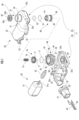
- FIG. 1 is an exploded perspective view showing one embodiment of a rotation actuator according to the present invention
- FIG. 2 is a perspective view of the rotary actuator with a second case removed.
- FIG. FIG. 2 is an enlarged perspective view of a first rotating body, a second rotating body, and a third rotating body that configure the rotation actuator.
- 5 is an enlarged perspective view of a second rotating body and a third rotating body that configure the rotation actuator, as viewed from a different direction than in FIG. 4 .
- FIG. 2 is a plan view illustrating a first rotating body that constitutes the rotation actuator, in a state where the first rotating body is not rotating.
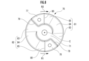
- 7 is an explanatory plan view of a state in which a first rotating body rotates in a first rotation direction from the state shown in FIG. 6;
- FIG. 13 is a bottom view of a third rotating body that constitutes the rotation actuator.
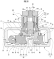
- 4 is a cross-sectional view taken along the line AA of FIG. 3.
- 4 is a cross-sectional view taken along the line BB of FIG. 3.
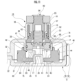
- 10 is a cross-sectional view of a state in which the driving member is driven from the state shown in FIG. 9 to rotate the first rotor in a first rotation direction and connect the third rotor to the second rotor.
- FIG. 13 is a schematic explanatory diagram showing a case where a rotary actuator of the present invention is applied to a first member and a second member that reciprocate, in which the second member, that is, an accommodation member, is stored in a storage section of a ceiling wall, that is, the first member.
- FIG. 13 is a schematic explanatory diagram of a case in which the storage member is opened from the storage portion of the ceiling wall in the state of FIG. 12 .
- FIG. FIG. 13 is a perspective view showing another embodiment of a rotary actuator according to the present invention, with a second case removed.
- 4 is a cross-sectional view of the rotary actuator in a state where a third rotary body is separated from a second rotary body.
- FIG. 16 is a cross-sectional view of a case where the driving member is driven from the state shown in FIG. 15 to rotate the first rotor in a first rotation direction and connect the third rotor to the second rotor.
- This rotary actuator is disposed between a first member and a second member, the first member and/or the second member being structured to reciprocate, and controls the reciprocating motion of the first member and/or the second member.
- the rotary actuator 10 is disposed between a first member and a second member, one of which is structured so that it reciprocates relative to the other member, and controls the reciprocating motion of one of the members.
- a storage member 2 capable of storing glasses or the like may be provided on the ceiling wall 1 at the front of the automobile, and in such a case the rotary actuator 10 may be applied.
- the rotary actuator may be disposed between a first member and a second member that are structured to reciprocate relative to one another, and control the reciprocating motion of the first member and the second member (this will be described in more detail in the modified example).
- the ceiling wall 1 is provided with a storage section 3, which is a space that is open downward.
- a storage member 2 is rotatably attached to the ceiling wall 1 via a support shaft 4, and this storage member 2 is configured to be stored in and opened from the storage section 3.
- the storage member 2 is capable of reciprocating movement (reciprocating rotation movement) relative to the ceiling wall 1.
- the rotary actuator 10 in this embodiment controls the reciprocating rotation of the storage member 2 which rotates reciprocally relative to the ceiling wall 1.
- the above-mentioned ceiling wall 1 constitutes the "first member” in this invention, and the storage member 2 constitutes the “second member” in this invention.
- the storage member 2, which is the second member, constitutes the "one member,” and the ceiling wall 1, which is the first member, constitutes the "other member.”
- a gear 5 is attached to the outside of the storage member 2, and the gear 5 is screwed into a gear 65 fixed to the second rotating body 60 (see FIG. 1) of the rotary actuator 10.
- the gear 65 of the rotary actuator 10 rotates, the storage member 2 is stored in or opened from the storage section 3 of the ceiling wall 1 via the gear 5.
- the rotary actuator 10 is fixed to the side of the ceiling wall 1, which is the first member, via the case 11 by fixing means such as bolts and nuts (not shown) (see Figs. 12 and 13). Furthermore, the rotary actuator 10 is arranged on the first member side, with the components of the first rotating body 40, second rotating body 60, and third rotating body 70 shown in Fig. 1 housed within the case 11.
- the gear 65 fixed to the second rotating body 60 is adapted to screw into the gear 5 of the housing member 2, which is the second member.
- a locking device (not shown) is provided at a predetermined location on the storage section 3 and/or the storage member 2 to maintain the storage state when the storage member 2 is stored in the storage section 3.
- a drive switch (not shown) (such as a touch switch, push button switch, or lever switch) is provided at a predetermined location on the storage member 2 to drive the first rotating body 40 of the rotation actuator 10 to rotate.
- the rotary actuator 10 of this embodiment includes a case 11 consisting of a first case 20 and a second case 30, a first rotating body 40 that rotates in a first rotational direction R1 (see FIGS. 4 to 8) and a second rotational direction R2 (see FIGS. 4 to 8) opposite to the first rotational direction R1, a driving member 50 that rotates the first rotating body 40 in the first rotational direction R1 (hereinafter also simply referred to as "R1”) and the second rotational direction R2 (hereinafter also simply referred to as "R2”), and a drive member 50 that rotates in conjunction with the reciprocating motion of the first member and/or the second member.
- It has a second rotating body 60 (which rotates in conjunction with the reciprocating rotational movement of the second member, the housing member 2), a third rotating body 70 that is arranged coaxially with the second rotating body 60 and axially movable so as to connect and disconnect to the second rotating body 60, and rotates in conjunction with the first rotating body 40, a biasing member 15 (here a coil spring) that biases the third rotating body 70 in a direction to disconnect it from the second rotating body 60, and a cam mechanism that connects and disconnects the third rotating body 70 to and from the second rotating body 60.
- a biasing member 15 here a coil spring
- the cam mechanism performs a first operation of connecting the third rotating body 70 to the second rotating body 60 against the biasing force of the biasing member 15 when the first rotating body 40 rotates in the first rotational direction R1, and a second operation of disconnecting the third rotating body 70 from the second rotating body 60 together with the biasing force of the biasing member 15 (the biasing force of the biasing member 15 that biases the third rotating body 70 in a direction to disconnect it from the second rotating body 60) when the first rotating body 40 rotates in the second rotational direction R2.
- the rotary actuator 10 of this embodiment further has a braking structure that brakes the rotational motion of the second rotating body 60.
- the driving member 50 in this embodiment is a motor that is driven to rotate electrically.
- the driving member 50 is made up of a motor body 51 and a gear 52 that is fixed to the drive shaft 51a of the motor body 51 in a rotation-restricted state.
- the gear 52 extends a predetermined length and has spiral teeth formed on its outer periphery, making it a so-called worm gear.
- the case 11 in this embodiment is composed of a first case 20 and a second case 30 that is assembled to the first case 20.
- the first rotating body 40, the driving member 50, the second rotating body 60, the biasing member 15, and the third rotating body 70 are housed in a case 11, and a rotational resistance imparting member 17 is disposed between the case 11 and the third rotating body 70, and applies a predetermined rotational resistance to the third rotating body 70 when the first rotating body 40 rotates in the first rotational direction R1 (see Figures 9 to 11).
- case 11 has a cylindrical portion that is inserted between the inside of the storage recess 43 of the first rotating body 40 and the outside of the third rotating body 70 to guide the rotational movement of the first rotating body 40 and the third rotating body 70.
- the first case 20 has a bottom wall 21 and a peripheral wall 22 erected from the periphery thereof, and is a bottomed frame-like structure with an opening on the side facing the second case 30 (upper side).
- the first case 20 also has a first arrangement section 23 in which the motor body 51 is arranged, and a second arrangement section 24 that is provided adjacent to the first arrangement section 23 and in which the gear 52 and the first rotating body 40 are arranged. Furthermore, a connector insertion section 25 is provided on one side of the first arrangement section 23 of the first case 20.
- a plurality of engagement pieces 22a are provided at predetermined locations on the outer periphery of the peripheral wall 22 for assembly with the second case 30.
- a support shaft 26 with a circular outer periphery protrudes from the inner surface of the bottom wall 21 on the second arrangement section 24 side, and rotatably supports the first rotating body 40. This support shaft 26 extends perpendicular to the surface direction of the inner surface of the bottom wall 21.
- the rotational axis direction of the first rotating body 40, second rotating body 60, and third rotating body 70 described below, i.e., the direction along the axis passing through the rotation center C of each rotating body 40, 60, and 70, is the same as the direction of the support shaft 26 described above.
- the second case 30, which is assembled to the first case 20, has a ceiling wall 31 and a peripheral wall 32 that hangs down from its periphery, and is frame-shaped with an opening on the side facing the first case 20 (the lower side).
- the second case 30 is provided with a first arrangement portion 33, a second arrangement portion 34, and a connector insertion portion 35 at positions corresponding to the first arrangement portion 23, the second arrangement portion 24, and the connector insertion portion 25 of the first case 20, respectively.
- a plurality of engagement protrusions 32a are provided on the outer periphery of the peripheral wall 32 at positions corresponding to the plurality of engagement pieces 22a of the first case 20.
- the first arrangement sections 23, 33 provide an arrangement space for the motor body 51
- the second arrangement sections 24, 34 provide an arrangement space for the gear 52
- the first rotating body 40 the second rotating body 60
- the connector insertion sections 25, 35 provide a connector insertion space into which a power connector (not shown) that supplies electricity to the drive member 50 is inserted.
- a roughly cylindrical connector case 27, separate from the case 11, is assembled in the connector insertion space (see FIG. 1).
- a pair of bus bars 54, 54 are arranged inside this connector case 27, and a power connector (not shown) is inserted to supply electricity to the drive member 50.
- the motor body 51 which is disposed in the space of the case 11, is electrically connected to a power connector (not shown) via a pair of bus bars 54, 54, and the drive shaft 51a rotates in a predetermined direction by turning on a drive switch provided on the housing member 2.
- a substantially cylindrical tube portion 36 is provided at a predetermined location on the ceiling wall 31 of the second case 30 on the second placement section 34 side.
- this tubular portion 36 has a first tubular portion 37 that extends upward a predetermined length from the outer surface of the ceiling wall 31 (the surface opposite the surface facing the first case 20), and a second tubular portion 38 that extends downward a predetermined length from the inner surface of the ceiling wall 31 (the surface facing the first case 20), coaxially with the first tubular portion 37 and with a slightly larger diameter than the first tubular portion 37. Both tubular portions 37, 38 extend perpendicular to the surface direction of the ceiling wall 31.
- the first tube portion 37 has a double-tube structure with an outer tube wall 37a and an inner tube wall 37b arranged inside the outer tube wall 37a.
- the base end portion 37c of the inner tube wall 37b has a smaller diameter than the tip end side via the ring support step portion 37d.
- the outer cylindrical portion 62 of the second rotating body 60 is inserted into the first cylindrical portion 37, and a viscous fluid such as oil is sealed in to form a braking structure (details will be described later).
- the tip end portion in the extending direction of the second tubular portion 38 is inserted between the inside of the accommodating recess 43 of the first rotating body 40 and the outside of the third rotating body 70.
- the tip end portion 38a in the extending direction of the second tubular portion 38 is inserted between the inside of the enlarged diameter portion 43a provided at the upper opening of the accommodating recess 43 of the first rotating body 40 and the outside of the base portion 71 of the third rotating body 70 and the outside of the rotational resistance imparting member 17 attached to the ring attachment groove 72 formed on the outside of the base portion 71.
- a portion of the third rotating body 70 is accommodated inside the tip portion 38a of the second tubular portion 38, and a portion of the first rotating body 40 including the accommodation recess 43 is disposed outside the tip portion 38a, making it possible to guide the rotational movement of the first rotating body 40 and the third rotating body 70.
- this second cylindrical portion 38 constitutes the "cylindrical portion" in the present invention.
- first rotating body 40 which rotates in a first rotation direction R1 and also in a second rotation direction R2 opposite to the first rotation direction R1.
- the first rotating body 40 also has a storage recess 43, in which the third rotating body 70 is arranged coaxially with the first rotating body 40.
- the first rotating body 40 in this embodiment has a bottom wall 41 in the shape of a substantially circular plate, and a cylindrical wall 42 erected from the outer periphery of the bottom wall 41.
- An accommodation recess 43 that is open upward is defined inside the bottom wall 41 and the cylindrical wall 42.
- the third rotating body 70 is accommodated in this accommodation recess 43 so that it can move up and down along the rotation axis direction of each rotating body 40, 60, 70.
- a circular support hole 41a is formed in the radial center of the bottom wall 41, and the support shaft 26 of the first case 20 is inserted into the support hole 41a, so that the first rotating body 40 is rotatably supported relative to the case 11.
- the inner circumference of the tip end of the cylindrical wall 42 in the vertical direction is larger in diameter than the base end in the vertical direction, and an expanded diameter portion 43a is formed on the upper opening side of the storage recess 43. As shown in Figures 9 to 11, one end of the second cylindrical portion 38 is inserted and positioned inside this expanded diameter portion 43a.
- teeth 44 are formed on the outer periphery of the cylindrical wall 42 in the form of helical teeth (angled teeth) that mesh with the gear 52 of the driving member 50.
- the teeth 44 are provided over the entire outer periphery of the cylindrical wall 42, and in a range from the base end (lower end) of the cylindrical wall 42 in the axial direction to slightly before the tip end (upper end) in the axial direction.
- each pressing protrusion 45, 46 has a generally trapezoidal protrusion shape that gradually narrows from the inner circumference of the cylindrical wall 42 toward the radial center (center of rotation C).
- each pressing protrusion 45, 46 extends from the inner surface of the bottom wall 41 along the axial direction of the cylindrical wall 42 to the expanded diameter portion 43a.
- the side surface of each pressing protrusion 45, 46 facing the first rotation direction R1 forms one side surface 47
- the side surface facing the second rotation direction R2 forms the other side surface 48.
- each pressing protrusion 45, 46 forms a cam abutment surface 49 that abuts against the cam surfaces 81, 82 (see Figure 5) of the third rotating body 70.
- each pressing protrusion 45, 46 is cut off to make it narrower than the axial lower end, and the cam abutment surface 49 is also narrow.
- This narrow shape prevents the cam abutment surface 49 from interfering with the base portion 83a of the first surface 83 of the cam surfaces 81, 82 (the R-shaped boundary portion between the first surface 83 and one side surface 79 of the pressed protrusion 77, 78, see Figures 4 and 5), and reliably prevents the connection portion 74 of the third rotating body 70 from becoming detached from the connection portion 66 of the second rotating body 60.
- the second rotating body 60 which is one of the members and rotates in conjunction with the reciprocating rotational motion of the second member, the housing member 2.
- the second rotating body 60 in this embodiment has a shaft portion 61 that extends a predetermined length in the direction of the rotation axis of the second rotating body 60 and has a circular outer periphery, a connecting portion 62a (see Figure 9) that protrudes radially outward from the outer periphery of the base end in the axial direction of the shaft portion 61, and a substantially cylindrical outer tube portion 62 that extends via the connecting portion 62a to form a double tube structure with a predetermined gap outside the shaft portion 61 and is inserted into the first tube portion 37 provided in the tube portion 36 of the second case 30.
- a ring mounting groove 62b is formed on the outer periphery of the base end of the outer tube portion 62, and a ring support step 62c is formed on the inner periphery of the base end of the outer tube portion 62, at a position closer to the axial tip than the ring mounting groove 62b.
- the first sealing ring S1 comes into contact with the inner circumference of the outer tube wall 37a, sealing the gap between the inner circumference of the outer tube wall 37a and the outer circumference of the outer tube portion 62, and the second sealing ring S2 is clamped by the ring support steps 62c, 37d, sealing the gap between the outer circumference of the inner tube wall 37b and the inner circumference of the outer tube portion 62, thereby sealing the viscous fluid.
- the first cylindrical portion 37, the outer cylindrical portion 62, the first sealing ring S1, the second sealing ring S2, and the viscous fluid form the "damping structure" of the present invention (a so-called oil damper).
- a spring accommodating space 63 is formed from the axial base end of the shaft portion 61 to the axial tip, and a stepped support portion 63a is formed in the axial middle of this spring accommodating space 63.
- the spring accommodating space 63 accommodates a portion of the biasing member 15, which is a coil spring, except for the axial base end, and the axial tip of the biasing member 15 abuts against and is supported by the support portion 63a.
- a gear connecting portion 64 protrudes from the axial tip of the shaft portion 61.
- This gear connecting portion 64 has a roughly rectangular shape with flat side surfaces and arc-shaped end surfaces, and a fitting groove 64a is formed on each surface.
- the gear 65 connected to this gear connecting part 64 has teeth formed on its outer circumference and has an irregularly shaped fitting hole 65a that fits the gear connecting part 64, and furthermore, a number of fitting protrusions 65b are protruding from the inner circumference of the fitting hole 65a. Then, when the gear connecting part 64 is inserted and fitted into the fitting hole 65a, the fitting protrusions 65b fit into the fitting groove 64a (see Figures 3 and 9), the gear 65 is held in place by the gear connecting part 64 in a state where its rotation is restricted and it does not come off.
- a connecting portion 66 in the form of an annular thick plate with a larger diameter than the outer cylinder portion 62 is connected to the axial base end of the outer cylinder portion 62.
- This connecting portion 66 is composed of a plurality of protrusions 67 protruding at a predetermined interval from the surface facing the third rotor 70 (the base end surface of the second rotor 60) so as to form a radial shape with respect to the center of rotation C of the second rotor 60, and a plurality of recesses 68 provided between the plurality of protrusions 67, 67, and is structured so that the protrusions 67 and recesses 68 are alternately provided in the circumferential direction.
- each protrusion 67 is wide on the radially outer side and gradually narrows toward the radially inner side, and both corners of the tip in the protruding direction are chamfered (see Figure 5).
- the third rotating body 70 which is arranged coaxially with the second rotating body 60 and axially movable so as to connect and disconnect with the second rotating body 60, and which rotates in conjunction with the first rotating body 40.
- the third rotating body 70 in this embodiment has a base 71 in the shape of a generally circular plate of a predetermined thickness, a connection portion 74 provided on the surface (front side) of the base 71 facing the second rotating body 60, a pair of pressed protrusions 77, 78 protruding from the surface (back side) of the base 71 facing the first rotating body 40, and a pair of cam surfaces 81, 82 provided on the back side of the base 71 between the pair of pressed protrusions 77, 78.
- a ring mounting groove 72 is formed on the outer periphery of the base 71.
- a circular ring-shaped rotational resistance imparting member 17 is mounted in this ring mounting groove 72.
- This rotational resistance imparting member 17 is arranged with its outer periphery abutting the inner periphery of the second cylindrical portion 38 of the cylindrical portion 36 of the second case 30 (see Figures 9 to 11).
- the third rotating body 70 rotates, it comes into sliding contact with the inner periphery of the second cylindrical portion 38, generating frictional resistance and imparting a predetermined rotational resistance to the third rotating body 70.
- a spring support recess 73 is formed in the radial center of the surface side of the base 71, forming a circular recess of a predetermined depth (see FIG. 4).
- the axial base end of the biasing member 15, which is a coil spring, is inserted into and supported by this spring support recess 73 (see FIG. 9).
- connection part 74 is provided on the surface side of the base part 71, on the outer periphery of the spring support recess 73.
- This connection part 74 is a part that is connected to the connection part 66 of the second rotating body 60, or is disconnected (a disconnecting part).
- connection portion 74 is made up of a number of protrusions 75 that protrude from the surface facing the second rotating body 60 at a predetermined interval so as to form a radial pattern with respect to the center of rotation C of the second rotating body 60, and a number of recesses 76 that are provided between the protrusions 75, 75, and the protrusions 75 and recesses 76 are arranged alternately in the circumferential direction.
- each protrusion 75 is wide on the radially outer side and gradually narrows toward the radially inner side, and both corners of the tip in the protruding direction are chamfered.
- the convex portions 67, 75 of the connecting portions 66, 74 of the second rotating body 60 and the third rotating body 70 are fitted into the concave portions 68, 76 of each other (see FIG. 11), so that the connection between the connecting portions 66, 74 is firmly maintained and the connection between the third rotating body 70 and the second rotating body 60 is maintained (it can also be said that the third rotating body 70 is fully connected to the second rotating body 60).
- connection portion 66 of the second rotating body 60 and the connection portion 74 of the third rotating body 70 are spaced apart from each other, and the convex portion 67 of the connection portion 66 of the second rotating body 60 and the convex portion 75 of the connection portion 74 of the third rotating body 70 are arranged opposite each other (see Figures 9 and 10). Therefore, as described above, when the third rotating body 70 is merely moved axially toward the connection portion 66 of the second rotating body 60 by the cam mechanism, the convex portions 67, 75 of both the connection portions 66, 74 of the second rotating body 60 and the third rotating body 70 do not fit into the concave portions 68, 76.
- the cam mechanism simply moves the third rotating body 70 axially toward the connection portion 66 of the second rotating body 60, and the convex portions 67, 75 of both connection portions 66, 74 of the second rotating body 60 and the third rotating body 70 engage with the concave portions 68, 76, thereby fully connecting the third rotating body 70 and the second rotating body 60. In other words, in this case, there is no need to rotate the third rotating body 70 in the R1 direction.
- a predetermined convex portion 75 of the connection portion 74 of the third rotating body 70 comes out of the corresponding concave portion 68 of the connection portion 66 of the second rotating body 60
- a predetermined convex portion 67 of the connection portion 66 of the second rotating body 60 comes out of the corresponding concave portion 76 of the connection portion 74 of the third rotating body 70, thereby releasing the connection between the two connection portions 66, 74, i.e., the two connection portions 66, 74 are disconnected, and the third rotating body 70 is disconnected from the second rotating body 60 (see Figures 9 and 10).
- a biasing member 15 is disposed in a compressed state between the spring accommodating space 63 of the second rotating body 60 and the spring support recess 73 of the third rotating body 70 (see Figures 9 and 10), and the biasing force of the biasing member 15 biases the connection portion 74 of the third rotating body 70 in a direction in which it is separated from the connection portion 66 of the second rotating body 60.
- each pressed protrusion 77, 78 protrude a predetermined length in the direction of the rotation axis from radially opposing locations on the outer periphery of the back side of the base 71 (it can also be said that they extend a predetermined length downward toward the first rotor 40).
- each pressed protrusion 77, 78 is a generally trapezoidal protrusion that is wide on the radial outside and gradually narrows toward the radial inside.
- each pressed protrusion 77, 78 facing the first rotation direction R1 forms one side surface 79
- the surface facing the second rotation direction R2 forms the other side surface 80.
- the pair of pressed protrusions 77, 78 are accommodated in the accommodation recess 43 of the first rotating body 40 and are arranged between the pair of pressing protrusions 45, 46 so as to be rotatable in the circumferential direction.
- connection portion 74 of the third rotating body 70 and the connection portion 66 of the second rotating body 60 are separated (see Figures 9 and 10), as shown in Figure 6, the pressing protrusion 45 and the pressed protrusion 78 are spaced apart from each other in the circumferential direction, and the pressing protrusion 46 and the pressed protrusion 77 are spaced apart from each other in the circumferential direction. Note that in Figures 6 and 7, only the pressed protrusions 77 and 78 of the third rotating body 70 are shown to make the drawings easier to understand.
- the cam mechanism causes the third rotating body 70 to move axially closer to the connection portion 66 of the second rotating body 60 (details will be described later), and then the pressing protrusion 45 presses the pressed protrusion 78 (one side 47 of the pressing protrusion 45 presses the other side 80 of the pressed protrusion 78), and the pressing protrusion 46 presses the pressed protrusion 77 (one side 47 of the pressing protrusion 46 presses the other side 80 of the pressed protrusion 77).
- the third rotating body 70 rotates in the R1 direction in conjunction with the first rotating body 40.
- the connection portion 74 of the third rotating body 70 and the connection portion 66 of the second rotating body 60 are connected (see FIG. 11).
- the cam mechanism together with the biasing force of the biasing member 15, moves the third rotating body 70 axially away from the connection portion 66 of the second rotating body 60 (details will be described later).
- the pressing protrusion 45 presses the pressed protrusion 77 (the other side 48 of the pressing protrusion 45 presses one side 79 of the pressed protrusion 77), and the pressing protrusion 46 presses the pressed protrusion 78 (the other side 48 of the pressing protrusion 46 presses one side 79 of the pressed protrusion 78).
- the third rotating body 70 rotates in the R2 direction in conjunction with the first rotating body 40, and the pressing protrusion 45 and the pressed protrusion 78, and the pressing protrusion 46 and the pressed protrusion 77 return to the state shown in FIG. 6.
- the cam surface 81 is formed in the circumferential region from one side surface 79 of the pressed protrusion 78 to the other side surface 80 of the pressed protrusion 77, and has a flat first surface 83 arranged adjacent to one side surface 79 of the pressed protrusion 78 and flush with the rear surface of the base 71, a second surface 84 that extends from the circumferential tip of the first surface 83 (the end separated from the one side surface 79 of the pressed protrusion 78) along the circumferential direction of the base 71 and gradually protrudes toward the axial base end side (downward), and a flat third surface 85 that extends from the circumferential tip of the second surface 84 toward the other side surface 80 of the pressed protrusion 77.
- the cam surface 82 is formed in the circumferential region from one side surface 79 of the pressed protrusion 77 to the other side surface 80 of the pressed protrusion 78, and has a flat first surface 83 that is arranged adjacent to one side surface 79 of the pressed protrusion 77 and is flush with the rear surface of the base 71, a second surface 84 that extends from the circumferential tip of the first surface 83 (the end portion separated from the one side surface 79 of the pressed protrusion 77) along the circumferential direction of the base 71 and is inclined so as to gradually protrude toward the axial base end side (downward), and a third surface 85 that is provided in a flat shape from the circumferential tip of the second surface 84 toward the other side surface 80 of the pressed protrusion 78.
- each cam surface 81, 82 is located at the position farthest from the protruding tip of the pressed protrusion 77, 78, i.e., at the position with the highest axial height among the cam surfaces 81
- the third surface 85 is located at the position closest to the protruding tip of the pressed protrusion 77, 78, i.e., at the position with the lowest axial height among the cam surfaces 81
- the second surface 84 is located so as to gradually decrease in height from the circumferential tip of the first surface 83 toward the third surface 85.
- the cam surfaces 81, 82 on the third rotating body 70 and the cam contact surface 49 on the second rotating body 60 form the "cam mechanism" of the present invention.
- This cam mechanism also serves to move the third rotating body 70 up and down in the axial direction by the cam contact surface 49 sliding between the first surface 83 and the third surface 85 of the cam surfaces 81, 82, which have a height difference, via the second surface 84 (described in detail later).
- the first surface 83 of the cam surface 81 is disposed on the cam abutment surface 49 of the pressing protrusion 46 (the first surface 83 of the cam surface 81 and the cam abutment surface 49 of the pressing protrusion 46 are disposed opposite each other), and the first surface 83 of the cam surface 82 is disposed on the cam abutment surface 49 of the pressing protrusion 45 (the first surface 83 of the cam surface 82 and the cam abutment surface 49 of the pressing protrusion 45 are disposed opposite each other).
- the cam abutment surface 49 slides and moves on the cam surfaces 81, 82 from the first surface 83, which is the highest of the cam surfaces 81, 82, through the second surface 84 to the third surface 85, which is the lowest, so that the third rotating body 70 is pushed up by moving axially against the biasing force of the biasing member 15 so as to approach the connection portion 66 of the second rotating body 60, as shown by the arrow F2 in Figure 10.
- connection portion 74 of the third rotating body 70 abuts against the protrusion 67 of the connection portion 66 of the second rotating body 60, connecting the two connection portions 66, 74, and performing the first operation of connecting the third rotating body 70 to the second rotating body 60 against the biasing force of the biasing member 15.
- the pressing protrusion 45 presses the pressed protrusion 78
- the pressing protrusion 46 presses the pressed protrusion 77, so that the third rotating body 70 rotates in the R1 direction in conjunction with the first rotating body 40, as shown in FIG. 7.
- the protrusion 75 of the connection portion 74 of the third rotating body 70 shifts in position in the circumferential direction relative to the protrusion 67 of the connection portion 66 of the second rotating body 60, and a timing occurs where it aligns with the recess 68 of the connection portion 66.
- the convex portions 67, 75 of the connecting portions 66, 74 of the second rotating body 60 and the third rotating body 70 fit into the concave portions 68, 76 of each other, so that the first operation described above, that is, connecting the third rotating body 70 to the second rotating body 60 against the biasing force of the biasing member 15, is more reliably performed (it can also be said that the first operation is maintained).
- connection parts 66, 74 When both connection parts 66, 74 are connected, the first rotating body 40 and the second rotating body 60 are connected in the axial direction via the third rotating body 70, so that the second rotating body 60 rotates in the same direction as the first rotating body 40.
- the third rotating body 70 is pushed away from the connection portion 66 side of the second rotating body 60 by the biasing force of the biasing member 15 which biases the third rotating body 70 in a direction to separate it from the second rotating body 60, and the cam abutment surface 49 of the pressing protrusion 46 located on the third surface 85 of the cam surface 81 slides on the second surface 84 of the cam surface 81 and moves to the first surface 83 of the cam surface 81, and the cam abutment surface 49 of the pressing protrusion 45 located on the third surface 85 of the cam surface 82 slides on the second surface 84 of the cam surface 82 and moves to the first surface 83 of the cam surface 82, so that the third rotating body 70 is pushed down in a direction to separate it from the connection portion 66 side of the second rotating body 60, and the second operation of separating the third rotating body 70 from the second rotating body 60 is performed.
- the cam mechanism performs the second operation together with the biasing force of the biasing member 15, thereby separating the third rotating body 70 from the second rotating body 60.
- the third rotating body 70 is separated from the second rotating body 60 by the cooperation of the biasing member 15 and the cam mechanism, i.e., the operation of the biasing member 15 to bias the third rotating body 70 in a direction to separate it from the second rotating body 60, and the operation of the cam mechanism to move the third rotating body 70 in a direction away from the second rotating body 60.
- the pressing protrusion 45 presses the pressed protrusion 77
- the pressing protrusion 46 presses the pressed protrusion 78, so that the third rotating body 70 rotates in the R2 direction in conjunction with the first rotating body 40.
- the convex portion 75 of the connection portion 74 of the third rotating body 70 shifts circumferentially relative to the concave portion 68 of the connection portion 66 of the first rotating body 40, and the first surface 83 of the cam surface 81 is positioned on the cam abutment surface 49 of the pressing protrusion 46, and the first surface 83 of the cam surface 82 is positioned on the cam abutment surface 49 of the pressing protrusion 45.
- connection parts 66, 74 When both connection parts 66, 74 are disconnected, the second rotating body 60 does not rotate in conjunction with the first rotating body 40 (does not rotate together in conjunction with it), but rotates independently of the first rotating body 40.
- the rotary actuator 10 in this embodiment is applied to a pair of members consisting of a ceiling wall 1 and a housing member 2, with the housing member 2 being one member and the second member, moving in a reciprocating rotational motion relative to the ceiling wall 1 being the other member and the first member, but the rotary actuator may also be applied to a structure in which, for example, one member moves in a reciprocating sliding motion in a linear direction relative to the other member, or even to a structure such as the one below.
- the rotary actuator may be disposed between a first member and a second member that are structured to reciprocate relative to each other, and control the reciprocating motion of the first member and the second member, for example, a locking device for an opening/closing body that is openably and closably attached to the opening of a fixed body.
- the locking device has a structure including a locking section provided on either the fixed body or the opening/closing body, a pair of rods with hook sections at their tip ends that engage with and disengage from the locking section and that are capable of sliding movement, and biasing means (such as a tension spring) that biases each hook section in the direction of engaging with the locking section.
- biasing means such as a tension spring
- rack grooves are formed at the base end of each rod, and pinion gears fixed to the second rotating body of the rotary actuator mesh with these rack grooves.
- One of the rods constitutes the first member, and the other rod constitutes the second member.
- the first rotor is rotated in a first rotational direction by the driving member and connected to the second rotor via the third rotor by the cam mechanism.
- the second rotor rotates in the first rotational direction
- the base end of one rod slides through the pinion gear to overlap the base end of the other rod in the axial direction by a predetermined length against the biasing force of the biasing means (the pair of rods slide in the direction of retraction).
- the hook portions of the rods come out of the locking portion, and the opening/closing body is unlocked, allowing the opening/closing body to be opened from the opening of the fixed body.
- the rotation time and rotation speed of the first rotating body in the first rotation direction and the second rotation direction caused by the driving member can be changed as appropriate depending on the structure of the reciprocating movement of the first member and the second member, the installation location of the rotary actuator, the purpose of use, etc., and further, the rotation time of the first rotating body, etc. is appropriately controlled by a control structure, control circuit, etc. (not shown).
- the time during which current is passed when the first rotating body is rotated in the first rotation direction by the driving member may be set to be longer, shorter, or the same as the time during which current is passed when the first rotating body is rotated in the second rotation direction, or the rotation speed of the first rotating body in the first rotation direction by the driving member may be set to be faster, slower, or the same as the rotation speed in the second rotation direction.
- the drive member is controlled so that the first rotating body rotates in the first rotation direction (for example, electricity is applied for about 0.4 seconds).
- the first rotating body rotates in the second rotation direction, and the drive member is controlled so that the second rotating body rotates independently (in this case, electricity is passed for a time shorter than the time that electricity is passed in the first rotation direction, for example, about 0.1 seconds).
- the rotary actuator 10 in this embodiment is fixed to the ceiling wall 1, which is the first member, but it may also be disposed on the second member.
- biasing member 15 in this embodiment is made of a coil spring
- the biasing member may be something other than a coil spring, as long as it can bias the third rotating body in a direction that separates it from the second rotating body.
- the cam mechanism in this embodiment is made up of cam contact surface 49 and cam surfaces 81, 82, but it is sufficient that the cam mechanism is capable of performing a first operation of connecting the third rotating body to the second rotating body, and a second operation of releasing the first operation and disconnecting the third rotating body from the second rotating body.
- the cam mechanism in this embodiment basically has the function of moving the third rotor up and down in the axial direction in conjunction with the rotation of the first rotor, but the cam mechanism may also be configured to move the third rotor axially and rotate it in a predetermined direction in conjunction with the rotation of the first rotor.
- the third rotating body 70 when reliably connecting the third rotating body 70 to the second rotating body 60 (main connection), a rotational movement of the third rotating body 70 in the R1 direction is required, but for example, the third rotating body may be connected to the second rotating body only by axial movement of the third rotating body by a cam mechanism in a direction approaching the second rotating body.
- the third rotating body 70 is connected to and disconnected from the second rotating body 60 by the connection portion 74 of the third rotating body 70 and the connection portion 66 of the second rotating body 60 coming into contact with and separating from each other.
- the connection structure between the third rotating body and the second rotating body may be, for example, by attaching or bonding a member with high frictional resistance to the opposing surfaces of the third rotating body and/or the second rotating body, or by processing or attaching a material that increases frictional resistance.
- the braking structure for braking the rotational movement of the second rotating body 60 in this embodiment is a so-called oil damper that utilizes the shear resistance of a viscous fluid, but the braking structure may also be one that utilizes, for example, frictional resistance (this will be described in other embodiments).
- the driving member 50 in this embodiment is a motor
- the driving member may be, for example, an electric actuator or a hydraulic actuator, etc., as long as it is capable of rotating the first rotating body.
- the gear 52 of the driving member 50 is a worm gear
- the teeth 44 on the outer periphery of the first rotating body 40 are helical (hinged) teeth
- the configuration for rotating the first rotating body may be, for example, such that the gear on the driving member side has spur teeth, and spur teeth that mesh with the spur teeth are formed on the outer periphery of the first rotating body, as long as the first rotating body is rotatable.
- the biasing member and cam mechanism are configured as follows: "The biasing member biases the third rotating body in a direction to separate it from the second rotating body, and the cam mechanism connects and disconnects the third rotating body to and from the second rotating body, and the cam mechanism performs a first operation of connecting the third rotating body to the second rotating body against the biasing force of the biasing member when the first rotating body rotates in the first rotational direction, and a second operation of disconnecting the third rotating body from the second rotating body together with the biasing force of the biasing member when the first rotating body rotates in the second rotational direction.”
- the biasing member and cam mechanism in the rotary actuator may be configured as follows: "The biasing member biases the third rotating body in a direction to separate it from the second rotating body, and the cam mechanism moves the third rotating body in the axial direction so as to connect and separate it from the second rotating body, and the cam mechanism performs a first operation to connect the third rotating body to the second rotating body against the biasing force of the biasing member when the first rotating body rotates in the first rotational direction, and a second operation to separate the third rotating body from the second rotating body when the first rotating body rotates in the second rotational direction, and the third rotating body is separated from the second rotating body by the biasing force of the biasing member and the second operation of the cam mechanism.”
- Figure 12 shows the state in which the storage member 2 is stored in the storage section 3 of the ceiling wall 1 and locked by a locking device (not shown).
- the third rotating body 70 is separated from the second rotating body 60 by the biasing force of the biasing member 15 arranged in a compressed state between the spring storage space 63 of the second rotating body 60 and the spring support recess 73 of the third rotating body 70.
- the storage member 2 opens from the storage section 3 in the ceiling wall 1 via the support shaft 4 due to its own weight.
- the third rotating body 70 is separated (disconnected) from the second rotating body 60, so the second rotating body 60 can rotate independently.
- the gear 65 fixed coaxially to the second rotating body 60 rotates in mesh with the outer gear 5 of the storage member 2, causing the outer tubular portion 62 of the second rotating body 60 to rotate relative to the first tubular portion 37 of the tubular portion 36 of the case 11, and the rotational movement of the second rotating body 60 is braked by the brake structure. Therefore, the storage member 2 slowly opens from the storage section 3 of the ceiling wall 1 in the direction indicated by the arrow in FIG. 12, and reaches the state shown in FIG. 13.
- the cam mechanism then causes the third rotating body 70 to move axially toward the connection portion 66 of the second rotating body 60 against the biasing force of the biasing member 15, and is pushed up, performing a first operation of connecting the third rotating body 70 to the second rotating body 60, and the third rotating body 70 rotates in the R1 direction in conjunction with the first rotating body 40, maintaining the connected state (see FIG. 11).
- the second rotating body 60 is unable to rotate independently, and the rotational force from the first rotating body 40 is transmitted to the second rotating body 60 via the third rotating body 70, so that the second rotating body 60 rotates in the same direction as the first rotating body 40 and the third rotating body 70, and the gear 65 fixed coaxially to the second rotating body 60 rotates the gear 5 on the outside of the storage member 2.
- the storage member 2 is rotated in the direction indicated by the arrow in FIG. 13, and the storage member 2 is stored in the storage section 3 of the ceiling wall 1 as shown in FIG. 12. This stored state is locked by a locking device (not shown).
- the gear 52 of the drive member 50 rotates in the opposite direction to that described above, and the first rotating body 40 rotates in the R2 direction.
- the cam mechanism together with the biasing force of the biasing member 15, performs a second operation to separate the third rotating body 70 from the second rotating body 60, and the third rotating body 70 rotates in the R2 direction in conjunction with the first rotating body 40, maintaining the separated state.
- the third rotating body 70 is separated from the second rotating body 60, and the second rotating body 60 returns to its initial state in which it can rotate independently.
- the rotational force from the first rotating body 40 is transmitted to the second rotating body 60 via the third rotating body 70, so that one of the first member or the second member can move forward relative to the other member.
- the storage member 2, which is one of the members and is the second member can rotate (rotate forward) in a direction approaching the ceiling wall 1, which is the first member.
- the cam mechanism performs a second operation together with the biasing force of the biasing member 15, and the third rotating body 70 moves axially and is separated from the second rotating body 60.
- the rotational force from the first rotating body 40 cannot be transmitted to the second rotating body 60, so that one of the first member or the second member can move back and forth relative to the other member.
- the storage member 2, which is the second member and does not form one of the members can rotate (return) in a direction away from the ceiling wall 1, which is the first member.
- the second action of the cam mechanism performed together with the biasing force of the biasing member 15, moves the third rotating body 70 in the axial direction and becomes detached from the second rotating body 60, so that the second rotating body 60 can rotate independently of the first rotating body 40 and the third rotating body 70.
- the present invention can be widely applied to first and second members that are structured so that one of the first and second members reciprocates relative to the other member.
- the rotary actuator is disposed between a first member and a second member that are structured to reciprocate relative to each other, and controls the reciprocating motion of the first member and the second member (such as the locking device for an opening/closing body having a pair of rods, as described in the modified example).
- this embodiment further includes a braking structure that brakes the rotational movement of the second rotating body 60.
- a braking structure for applying a braking force to the rotational movement of the second rotating body 60 when the second rotating body 60 rotates in the R2 direction (a so-called oil damper in this embodiment), so that an appropriate braking force can be applied when the second rotating body 60 is in a state where it can rotate independently.
- the first rotating body 40, the driving member 50, the second rotating body 60, the biasing member 15, and the third rotating body 70 are housed in a case 11, and a rotational resistance imparting member 17 is disposed between the case 11 and the third rotating body 70, which imparts a predetermined rotational resistance to the third rotating body 70 when the first rotating body 40 rotates in the first rotational direction R1.
- the rotational resistance applying member 17 which applies a predetermined rotational resistance to the third rotating body 70 when the first rotating body 40 rotates in the R1 direction, is disposed between the case 11 and the third rotating body 70. Therefore, when the first rotating body 40 rotates in the R1 direction, the first rotating body 40 and the third rotating body 70 can be prevented from rotating together before the cam abutment surface 49 moves from the first surface 83 to the third surface 85 of the cam surfaces 81, 82, and the first operation by the cam mechanism can be reliably performed.
- the first rotating body 40 has a storage recess 43
- the third rotating body 70 is arranged to be stored in the storage recess 43 coaxially with the first rotating body 40.
- the third rotating body 70 is accommodated and arranged coaxially with the first rotating body 40 in the accommodation recess 43 of the first rotating body 40, so that the third rotating body 70 is prevented from becoming bulky in the axial direction, and the entire rotary actuator 10 can be made compact.
- first and second operations of the cam mechanism can guide the movement of the third rotating body 70, which moves to connect or disconnect with respect to the second rotating body 60, so that the connection or disconnection operation of the third rotating body 70 with respect to the second rotating body 60 can be performed stably.
- the first rotating body 40, the driving member 50, the second rotating body 60, the biasing member 15, and the third rotating body 70 are housed in a case 11, and the case 11 has a cylindrical portion (here, the second cylindrical portion 38) that is inserted between the inside of the housing recess 43 of the first rotating body 40 and the outside of the third rotating body 70 to guide the rotational movement of the first rotating body 40 and the third rotating body 70.
- the first rotating body 40 and the third rotating body 70 can share a guide for the rotational motion, thereby simplifying the structure of the rotary actuator 10.
- (Other embodiments of the rotary actuator) 14 to 16 show another embodiment of the rotary actuator according to the present invention. Note that parts that are substantially the same as those in the above embodiment are given the same reference numerals and the description thereof will be omitted.
- the rotational actuator 10A of this embodiment has a braking structure for braking the rotational motion of the second rotating body 60 that is different from the previous embodiment.
- the ring mounting groove 62b provided in the outer tube portion 62 of the second rotating body 60A has a base end portion provided on the outer periphery of the base end of the outer tube portion 62 and an oblique extension portion extending obliquely upward from this portion toward the tip side of the outer tube portion 62, and a seal ring 19 is attached to the base end portion and the oblique extension portion.
- this seal ring 19 slides against the inner circumference of the first cylindrical portion 37 of the cylindrical portion 36 of the second case 30, thereby applying a braking force when the second rotating body 60 rotates.
- the third rotating body 70 is normally biased in a direction to separate from the second rotating body 60 by the biasing force of the biasing member 15, so that the second rotating body 60 is in an independently rotatable state (see FIG. 15), and when the first rotating body 40 is rotated in the R1 direction by the driving member 50, the third rotating body 70 is pressed against the biasing force of the biasing member 15 toward the second rotating body 60 by the first action of the cam mechanism, moving in the axial direction, so that the third rotating body 70 is connected to the second rotating body 60 (see FIG. 16). Therefore, the same effect as in the previous embodiment can be obtained.
Landscapes
- Engineering & Computer Science (AREA)
- General Engineering & Computer Science (AREA)
- Mechanical Engineering (AREA)
- Transmission Devices (AREA)
Priority Applications (1)
| Application Number | Priority Date | Filing Date | Title |
|---|---|---|---|
| JP2025510854A JPWO2024204059A1 (https=) | 2023-03-29 | 2024-03-25 |
Applications Claiming Priority (2)
| Application Number | Priority Date | Filing Date | Title |
|---|---|---|---|
| JP2023054239 | 2023-03-29 | ||
| JP2023-054239 | 2023-03-29 |
Publications (1)
| Publication Number | Publication Date |
|---|---|
| WO2024204059A1 true WO2024204059A1 (ja) | 2024-10-03 |
Family
ID=92905320
Family Applications (1)
| Application Number | Title | Priority Date | Filing Date |
|---|---|---|---|
| PCT/JP2024/011698 Ceased WO2024204059A1 (ja) | 2023-03-29 | 2024-03-25 | 回転アクチュエータ |
Country Status (2)
| Country | Link |
|---|---|
| JP (1) | JPWO2024204059A1 (https=) |
| WO (1) | WO2024204059A1 (https=) |
Citations (2)
| Publication number | Priority date | Publication date | Assignee | Title |
|---|---|---|---|---|
| JPH0159476U (https=) * | 1987-10-09 | 1989-04-14 | ||
| JP2013061049A (ja) * | 2011-09-15 | 2013-04-04 | Nifco Inc | クラッチ |
-
2024
- 2024-03-25 JP JP2025510854A patent/JPWO2024204059A1/ja active Pending
- 2024-03-25 WO PCT/JP2024/011698 patent/WO2024204059A1/ja not_active Ceased
Patent Citations (2)
| Publication number | Priority date | Publication date | Assignee | Title |
|---|---|---|---|---|
| JPH0159476U (https=) * | 1987-10-09 | 1989-04-14 | ||
| JP2013061049A (ja) * | 2011-09-15 | 2013-04-04 | Nifco Inc | クラッチ |
Also Published As
| Publication number | Publication date |
|---|---|
| JPWO2024204059A1 (https=) | 2024-10-03 |
Similar Documents
| Publication | Publication Date | Title |
|---|---|---|
| CN111902650B (zh) | 盘式制动器以及行星齿轮减速机构 | |
| CN113039374B (zh) | 具有提供软制动的主轴/螺母组件的制动系统 | |
| US7533594B2 (en) | Position control apparatus for steering column | |
| CN115244316B (zh) | 包括扭矩限制装置的致动驱动器 | |
| JP7163191B2 (ja) | ブレーキアセンブリのグループ | |
| JP4532555B2 (ja) | 自動車用ステアリングスピンドルロック装置 | |
| CN102753774A (zh) | 阻尼器 | |
| JP2009207889A (ja) | 自動車シート調節装置用、特に背もたれヒンジ部品用の揺動継手部品 | |
| KR20210157957A (ko) | 드럼 브레이크 장치 | |
| KR20210157956A (ko) | 드럼 브레이크 장치 | |
| JP2021524827A (ja) | 電気駆動アセンブリ | |
| CN110775029A (zh) | 电子停车制动用致动器 | |
| KR101930763B1 (ko) | 전자식 주차 브레이크용 액추에이터 | |
| WO2024204059A1 (ja) | 回転アクチュエータ | |
| JP6727178B2 (ja) | 電動パーキングブレーキ装置 | |
| KR20200099729A (ko) | 주차 브레이크 장치 | |
| CN1938494A (zh) | 带阻尼器的铰链 | |
| WO2019131153A1 (ja) | ブレーキ装置 | |
| CN109083998B (zh) | 一种快速释放机构的开关装置及线性致动器 | |
| KR20180133976A (ko) | 전자식 주차 브레이크용 액추에이터 | |
| JP2011241939A (ja) | クラッチ装置 | |
| US20250001991A1 (en) | Actuation device for a brake system | |
| CN120677092A (zh) | 用于主制动缸的操纵装置、用于液压制动系统的组件 | |
| CN113153053A (zh) | 摩擦片组与旋转阻尼器 | |
| JP5450265B2 (ja) | クラッチ装置及びアクチュエータ |
Legal Events
| Date | Code | Title | Description |
|---|---|---|---|
| 121 | Ep: the epo has been informed by wipo that ep was designated in this application |
Ref document number: 24780177 Country of ref document: EP Kind code of ref document: A1 |
|
| DPE1 | Request for preliminary examination filed after expiration of 19th month from priority date (pct application filed from 20040101) | ||
| ENP | Entry into the national phase |
Ref document number: 2025510854 Country of ref document: JP Kind code of ref document: A |
|
| WWE | Wipo information: entry into national phase |
Ref document number: 2025510854 Country of ref document: JP |
|
| NENP | Non-entry into the national phase |
Ref country code: DE |
|
| 122 | Ep: pct application non-entry in european phase |
Ref document number: 24780177 Country of ref document: EP Kind code of ref document: A1 |