WO2024203755A1 - 熱交換器および熱交換器の製造方法 - Google Patents
熱交換器および熱交換器の製造方法 Download PDFInfo
- Publication number
- WO2024203755A1 WO2024203755A1 PCT/JP2024/011115 JP2024011115W WO2024203755A1 WO 2024203755 A1 WO2024203755 A1 WO 2024203755A1 JP 2024011115 W JP2024011115 W JP 2024011115W WO 2024203755 A1 WO2024203755 A1 WO 2024203755A1
- Authority
- WO
- WIPO (PCT)
- Prior art keywords
- plate portion
- fin
- thick plate
- heat exchanger
- heat transfer
- Prior art date
- Legal status (The legal status is an assumption and is not a legal conclusion. Google has not performed a legal analysis and makes no representation as to the accuracy of the status listed.)
- Ceased
Links
Images


Classifications
-
- F—MECHANICAL ENGINEERING; LIGHTING; HEATING; WEAPONS; BLASTING
- F28—HEAT EXCHANGE IN GENERAL
- F28D—HEAT-EXCHANGE APPARATUS, NOT PROVIDED FOR IN ANOTHER SUBCLASS, IN WHICH THE HEAT-EXCHANGE MEDIA DO NOT COME INTO DIRECT CONTACT
- F28D1/00—Heat-exchange apparatus having stationary conduit assemblies for one heat-exchange medium only, the media being in contact with different sides of the conduit wall, in which the other heat-exchange medium is a large body of fluid, e.g. domestic or motor car radiators
- F28D1/02—Heat-exchange apparatus having stationary conduit assemblies for one heat-exchange medium only, the media being in contact with different sides of the conduit wall, in which the other heat-exchange medium is a large body of fluid, e.g. domestic or motor car radiators with heat-exchange conduits immersed in the body of fluid
- F28D1/04—Heat-exchange apparatus having stationary conduit assemblies for one heat-exchange medium only, the media being in contact with different sides of the conduit wall, in which the other heat-exchange medium is a large body of fluid, e.g. domestic or motor car radiators with heat-exchange conduits immersed in the body of fluid with tubular conduits
- F28D1/053—Heat-exchange apparatus having stationary conduit assemblies for one heat-exchange medium only, the media being in contact with different sides of the conduit wall, in which the other heat-exchange medium is a large body of fluid, e.g. domestic or motor car radiators with heat-exchange conduits immersed in the body of fluid with tubular conduits the conduits being straight
-
- F—MECHANICAL ENGINEERING; LIGHTING; HEATING; WEAPONS; BLASTING
- F28—HEAT EXCHANGE IN GENERAL
- F28F—DETAILS OF HEAT-EXCHANGE AND HEAT-TRANSFER APPARATUS, OF GENERAL APPLICATION
- F28F1/00—Tubular elements; Assemblies of tubular elements
- F28F1/10—Tubular elements and assemblies thereof with means for increasing heat-transfer area, e.g. with fins, with projections, with recesses
- F28F1/12—Tubular elements and assemblies thereof with means for increasing heat-transfer area, e.g. with fins, with projections, with recesses the means being only outside the tubular element
- F28F1/24—Tubular elements and assemblies thereof with means for increasing heat-transfer area, e.g. with fins, with projections, with recesses the means being only outside the tubular element and extending transversely
- F28F1/30—Tubular elements and assemblies thereof with means for increasing heat-transfer area, e.g. with fins, with projections, with recesses the means being only outside the tubular element and extending transversely the means being attachable to the element
Definitions
- This disclosure relates to a heat exchanger and a method for manufacturing a heat exchanger.
- heat exchangers In heat exchangers, the fins can sometimes become deformed during molding. As a result, heat exchangers have been developed that are equipped with fins that are less likely to deform during molding.
- Patent Document 1 discloses a heat exchanger that has a metal strip formed into a corrugated shape and has fins that are folded back on both ends of the metal strip in the band direction.
- the heat exchanger described in Patent Document 1 increases the rigidity of the fins by folding back both ends of the metal strip in the band direction, thereby preventing deformation of the fins themselves.
- this heat exchanger uses a large amount of metal material because of the amount of folding back the metal strip. As a result, material costs are high.
- the present disclosure has been made to solve the above problems, and aims to provide a heat exchanger that is highly rigid and can be manufactured using less material, and a method for manufacturing the heat exchanger.
- the heat exchanger of the present disclosure comprises a fin having a thick plate section and a thin plate section that is thinner than the thick plate section and adjacent to the thick plate section, at least one plate surface of which is uneven due to the thick plate section and the thin plate section being adjacent to each other, and a plurality of heat transfer tubes arranged in a direction perpendicular to the tube axis with the tube axes oriented parallel to each other, sandwiching the fin between them.
- the fin has a portion that protrudes further than the plurality of heat transfer tubes in at least one direction perpendicular to the tube axis and the arrangement direction of the heat transfer tubes.
- at least the thick plate section of the thick plate section and the thin plate section is provided in the protruding portion of the fin.
- the fin has a portion that protrudes further than the multiple heat transfer tubes in at least one direction perpendicular to the tube axis and the arrangement direction of the heat transfer tubes. Furthermore, the protruding portion of the fin is provided with at least a thick plate portion out of a thick plate portion and a thin plate portion. This provides higher rigidity than when the entire fin is made of a thin plate. Furthermore, to ensure rigidity, the fin can be manufactured using less material than when the entire fin is made of a thick plate.
- FIG. 1 is a perspective view of a heat exchanger according to a first embodiment of the present disclosure
- FIG. 1 is a front view of a heat exchanger according to a first embodiment of the present disclosure
- FIG. 1 is an enlarged perspective view of a part of a heat transfer tube included in a heat exchanger according to a first embodiment of the present disclosure and a part of a fin attached to the part of the heat transfer tube
- FIG. 1 is an enlarged top view of some fins included in a heat exchanger according to a first embodiment of the present disclosure.
- 5 is a cross-sectional view taken along the line VV shown in FIG. Flowchart of a method for manufacturing a heat exchanger according to the first embodiment of the present disclosure
- FIG. 1 is a conceptual diagram of a fin forming device used in a method for manufacturing a heat exchanger according to a first embodiment of the present disclosure.
- FIG. 1 is a conceptual diagram of a modified example of a fin forming device used in a method for manufacturing a heat exchanger according to a first embodiment of the present disclosure.
- FIG. 1 is a conceptual diagram of a rolling device used in a method for manufacturing a heat exchanger according to a first embodiment of the present disclosure.
- 1 is a cross-sectional view of a first modified example of a fin included in the heat exchanger according to the first embodiment of the present disclosure;
- FIG. 10 is a cross-sectional view of a second modified example of the fins included in the heat exchanger according to the first embodiment of the present disclosure;
- FIG. 13 is a cross-sectional view of a third modified example of the fins included in the heat exchanger according to the first embodiment of the present disclosure.
- FIG. 13 is an enlarged top view of a fourth modified example of the fins included in the heat exchanger according to the first embodiment of the present disclosure.
- 11B is a cross-sectional view taken along the line XIB-XIB shown in FIG.
- FIG. 11 is an enlarged top view of some fins included in a heat exchanger according to a second embodiment of the present disclosure.
- 13 is a cross-sectional view taken along line XIII-XIII shown in FIG. FIG.
- FIG. 11 is a partial cross-sectional view of a first modified example of a thick plate portion provided on a fin included in a heat exchanger according to the first embodiment of the present disclosure.
- FIG. 11 is a partial cross-sectional view of a second modified example of a thick plate portion provided on a fin included in the heat exchanger according to the first embodiment of the present disclosure.
- FIG. 13 is a partial cross-sectional view of a third modified example of a thick plate portion provided on a fin included in the heat exchanger according to the first embodiment of the present disclosure.
- FIG. 13 is a partial cross-sectional view of a fourth modified example of a thick plate portion provided on a fin included in the heat exchanger according to the first embodiment of the present disclosure.
- FIG. 11 is a partial cross-sectional view of a first modified example of a thick plate portion provided on a fin included in a heat exchanger according to the first embodiment of the present disclosure.
- FIG. 11 is a partial cross-sectional view of a second modified
- FIG. 13 is a partial cross-sectional view of a fifth modified example of a thick plate portion provided on a fin included in the heat exchanger according to the first embodiment of the present disclosure.
- FIG. 13 is a partial cross-sectional view of a sixth modified example of a thick plate portion provided on a fin included in the heat exchanger according to the first embodiment of the present disclosure.
- FIG. 13 is a partial cross-sectional view of a seventh modified example of a thick plate portion provided on a fin included in the heat exchanger according to the first embodiment of the present disclosure.
- FIG. 13 is a partial cross-sectional view of an eighth modified example of a thick plate portion provided on a fin included in the heat exchanger according to the first embodiment of the present disclosure.
- FIG. 13 is a partial cross-sectional view of a fifth modified example of a thick plate portion provided on a fin included in the heat exchanger according to the first embodiment of the present disclosure.
- FIG. 13 is a partial cross-sectional view of a sixth modified example of
- FIG. 13 is a partial cross-sectional view of a ninth modified example of a thick plate portion provided on a fin included in the heat exchanger according to the first embodiment of the present disclosure.
- FIG. 23 is a partial cross-sectional view of a tenth modified example of a thick plate portion provided on a fin included in the heat exchanger according to the first embodiment of the present disclosure.
- FIG. 19 is a partial cross-sectional view of an eleventh modified example of a thick plate portion provided on a fin included in the heat exchanger according to the first embodiment of the present disclosure.
- FIG. 23 is a partial cross-sectional view of a twelfth modified example of a thick plate portion provided on a fin included in the heat exchanger according to the first embodiment of the present disclosure.
- FIG. 23 is a partial cross-sectional view of a thirteenth modified example of a thick plate portion provided on a fin included in the heat exchanger according to the first embodiment of the present disclosure.
- FIG. 11 is a conceptual diagram of a first modified example of an arrangement pattern of thick plate portions and thin plate portions provided on fins included in a heat exchanger according to a second embodiment of the present disclosure.
- FIG. 13 is a conceptual diagram of a second modified example of an arrangement pattern of thick plate portions and thin plate portions provided on fins included in a heat exchanger according to a second embodiment of the present disclosure.
- FIG. 13 is a conceptual diagram of a third modified example of an arrangement pattern of thick plate portions and thin plate portions provided on fins included in a heat exchanger according to the second embodiment of the present disclosure.
- FIG. 11 is a conceptual diagram of a first modified example of an arrangement pattern of thick plate portions and thin plate portions provided on fins included in a heat exchanger according to a second embodiment of the present disclosure.
- FIG. 13 is a conceptual
- FIG. 13 is a conceptual diagram of a fourth modified example of an arrangement pattern of thick plate portions and thin plate portions provided on the fins of the heat exchanger according to the second embodiment of the present disclosure.
- FIG. 13 is a conceptual diagram of a fifth modified example of an arrangement pattern of thick plate portions and thin plate portions provided on fins included in a heat exchanger according to the second embodiment of the present disclosure.
- the heat exchanger according to the first embodiment is a heat exchanger in which the plate thickness of the fins themselves is changed to provide unevenness on the plate surfaces of the fins.
- the overall configuration of the heat exchanger will be described with reference to Figs. 1 to 3.
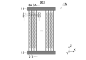
- FIG. 1 is a perspective view of a heat exchanger 1A according to the first embodiment.
- FIG. 2 is a front view of the heat exchanger 1A.
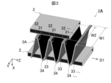
- FIG. 3 is an enlarged perspective view of a part of a heat transfer tube 2 provided in the heat exchanger 1A and a part of a fin 3A attached to the part of the heat transfer tube 2. Note that the fin 3A is omitted from FIG. 1 for ease of understanding.
- the shape of the fin 3A is simplified to a shape that is bent multiple times left and right when viewed from the front.
- the shape of the heat transfer tube 2 is simplified to a rectangular parallelepiped outer shape with the internal flow path omitted.
- the heat exchanger 1A is connected to external equipment and includes headers 11 and 12 through which the refrigerant is supplied and discharged, a plurality of heat transfer tubes 2 connected to the headers 11 and 12 and through which the refrigerant flows, and fins 3A attached to the heat transfer tubes 2.
- the headers 11 and 12 are formed in a cylindrical shape. Although not shown, the headers 11 and 12 are provided with connection pipes for connecting to external equipment that supplies and discharges the refrigerant. Furthermore, flow paths for distributing and collecting the refrigerant are formed inside the headers 11 and 12. As shown in FIG. 1, the headers 11 and 12 are arranged spaced apart from each other in the vertical direction with their cylindrical axes facing the left and right directions. A number of heat transfer tubes 2 are connected to the headers 11 and 12 to circulate the refrigerant between them.
- Each heat transfer tube 2 is formed in a tubular shape to allow the refrigerant to flow, with its tube axis facing up and down.
- the upper and lower ends of the heat transfer tubes 2 are inserted into insertion holes (not shown) in the cylindrical walls of the headers 11 and 12. As a result, when the refrigerant flows through the headers 11 and 12, the refrigerant circulates inside the heat transfer tubes 2.
- each heat transfer tube 2 is made of a metal with high thermal conductivity, such as pure aluminum or an aluminum alloy, to facilitate the transfer of heat from the refrigerant flowing through it. Furthermore, the heat transfer tubes 2 are formed in the shape of a flat tube with a flat tube cross section.
- the heat exchanger 1A is designed to exchange heat with air blown in the front-to-rear direction during use. To reduce the resistance of the air blown, the short axis of the flat tube cross section of the heat transfer tube 2 faces the left-to-right direction and the long axis faces the front-to-rear direction.
- the heat transfer tubes 2 are arranged in the left-to-right direction at regular intervals. Fins 3A are sandwiched between the heat transfer tubes 2, as shown in FIG. 2.
- the fins 3A have a corrugated plate shape in front view in order to increase the contact area with the air and improve the heat exchange performance with the air.
- the fins 3A are formed of a metal plate with high thermal conductivity, for example, a metal plate of pure aluminum or an aluminum alloy.
- the fins 3A are formed by bending the metal plate into a corrugated shape in which a plurality of peaks 31 and valleys 33 are adjacent to each other in one direction in a cross-sectional view.
- the fins 3A are sandwiched between the heat transfer tubes 2 with the direction in which the peaks 31 or valleys 33 are connected facing the tube axis direction D1 of the heat transfer tubes 2, i.e., the Z direction.
- the fins 3A are brazed to the heat transfer tubes 2 with the tops 32 and bottoms 34 in contact with the heat transfer tubes 2.
- fins 3A having such a corrugated shape may have a shape in which the width W1 in the front-to-rear direction, i.e., the Y direction, of the fin 3A is greater than the Y direction width W2 of the heat transfer tube 2.
- the fin 3A may be attached to the heat transfer tube 2 with its +Y end portion protruding in the +Y direction, on the leeward side, beyond the heat transfer tube 2 by 1/5 to 1/50 of the Y direction width W1 of the fin 3A.
- the fins 3A are formed to have such a width W1 shape and are positioned in such a protruding position, the +Y end portion of the fins 3A protruding in the +Y direction from the heat transfer tube 2 may become deformed by external forces such as collision or contact during manufacture or use.
- the fins 3A are being made thinner. For this reason, the strength and rigidity of the fins 3A themselves tend to decrease as the fins 3A are made thinner. As a result, if the fins 3A formed into the shape described above and arranged as described above are made even thinner, the ends of the fins 3A, including the +Y end, become more susceptible to deformation, making it difficult to manufacture the fins 3A into the desired shape. It also becomes difficult to use the fins 3A in their desired shape.
- the thickness of the fins 3A itself is changed to provide unevenness on the plate surface of the fins 3A.
- the detailed structure of the fins 3A will be described with reference to Figures 4 and 5.
- Figure 4 is an enlarged top view of some of the fins 3A provided in the heat exchanger 1A.
- Figure 5 is a cross-sectional view taken along the V-V section line shown in Figure 4. Note that, for ease of understanding, Figure 5 shows a cross-section of only the uppermost portion of the corrugated fin 3A when it is unfolded.
- fin 3A has a thick plate portion 35 provided at the +Y end portion and a thin plate portion 36 provided on the -Y side of thick plate portion 35 and adjacent to thick plate portion 35.
- the thickness T1 of the thick plate portion 35 is thicker than the thickness T2 of the thin plate portion 36.
- the difference between the thickness T1 of the thick plate portion 35 and the thickness T2 of the thin plate portion 36 is 10% to 90% of the thickness T1 of the plate portion 35.
- the thickness T1 of the thick plate portion 35 and the thickness T2 of the thin plate portion 36 are each constant.
- the center line CL1 of the thick plate portion 35 in a cross-sectional view is located on an extension of the center line CL2 of the thin plate portion 36 in a cross-sectional view.
- the thick plate portion 35 is adjacent to the thin plate portion 36.
- the thick plate portion 35 has a step between the thin plate portion 36 on one side of the plate surface of the fin 3A and the other side of the plate surface of the fin 3A.
- the thick plate portion 35 forms a protrusion 37 protruding from the thin plate portion 36 in the +Z direction on one side of the fin 3A, i.e., on the +Z surface.
- the thick plate portion 35 forms a protrusion 38 that protrudes from the thin plate portion 36 in the -Z direction on the other surface of the fin 3A, i.e., the -Z surface.
- the thick plate portion 35 and the thin plate portion 36 form unevenness on the +Z surface and the -Z surface of the fin 3A.
- the thick plate portion 35 and the thin plate portion 36 increase the strength and rigidity of the fin 3A.
- the thick plate portion 35 is provided at the +Y end portion of the fin 3A shown in FIG. 4, which protrudes in the +Y direction beyond the heat transfer tube 2.
- the width of the thick plate portion 35 in the Y direction is, for example, the same as or smaller than the +Y direction protruding length of the fin 3A. Or, it is smaller than the period, which is the distance between adjacent apexes 32 of the corrugation of the fin 3A, that is, the corrugation pitch.
- the width of the thick plate portion 35 in the Y direction is 1/5 to 1/50 of the width of the fin 3A in the Y direction.
- the thick plate portion 35 increases the strength and rigidity of the +Y end portion of the fin 3A.
- the thick plate portion 35 is provided at the +Y end portion of the fin 3A, thereby preventing deformation of the +Y end portion.
- the cross-sectional area of the thick plate portion 35 is larger than the cross-sectional area of the thin plate portion 36, and as a result, the thick plate portion 35 increases the strength and rigidity of the fin 3A.
- the thick plate portion 35 extends along each of the peak portions 31 and valley portions 33 that are connected in the Z direction of the corrugated shape of the fin 3A shown in FIG. 3. In other words, the thick plate portion 35 extends in a direction perpendicular to the width direction of the fin 3A. As a result, the thick plate portion 35 increases the strength and rigidity of the entire corrugated fin 3A, making it easier for the fin 3A to maintain its corrugated shape.
- the thin plate portion 36 has a number of cut-and-raised portions 39 formed therein to allow air to circulate around the fin 3A.
- the cut-and-raised portions 39 are formed by making cuts in the metal plate of the fin 3A and bending and standing up the portions of the metal plate adjacent to the cuts.
- the cut-and-raised portions 39 are formed in the thin plate portion 36 rather than in the thick plate portion 35, which makes it easier to manufacture the fin 3A.
- These thick plate portions 35 and thin plate portions 36 are formed by rolling the metal plate from which the fins 3A are made. Because the thin plate portions 36 are formed thinner than the metal plate from which the fins 3A are made, the fins 3A can be manufactured using less material in the manufacture of the heat exchanger 1A compared to a case in which the fins 3A are manufactured while leaving the thickness of the metal plate as is. Next, a method for manufacturing the heat exchanger 1A will be described with reference to Figures 6 and 7.
- Figure 6 is a flowchart of the manufacturing method for heat exchanger 1A.
- Figure 7 is a conceptual diagram of a fin forming device 40 used in the manufacturing method for heat exchanger 1A.
- the headers 11, 12 and heat transfer tubes 2 of the material, shape, and number described above are prepared.
- a rolling process (step S1) shown in FIG. 6 is performed to produce a plate member that is the material for the fins 3A.
- a fin forming process (step S2) is performed to produce the fins 3A from the produced plate member.
- a fin forming device 40 shown in FIG. 7 is used.
- the fin forming device 40 includes an uncoiler 42 that supports the core of a coil 41 around which a strip-shaped metal plate 4 is wound.
- the strip-shaped metal plate 4 is the raw material of the fin 3A, and is a strip-shaped metal sheet formed from a metal with high thermal conductivity, such as pure aluminum or an aluminum alloy.
- the fin forming device 40 pulls out the strip-shaped metal plate 4 from one end of the coil 41 by rotating the coil 41 with the uncoiler 42.
- the fin forming device 40 also includes a plurality of dancer rolls 43 around which the pulled-out strip-shaped metal plate 4 is wrapped, and a tension controller 44, so that the fin forming device 40 keeps the tension of the strip-shaped metal plate 4 at a constant level.
- the fin forming device 40 is provided with a plurality of pairs of rolling rolls 45 arranged vertically to form a pair in order to carry out the above-mentioned rolling process.
- the plurality of rolling rolls 45 have unevenness on their outer peripheries in order to form the above-mentioned thick plate portion 35 and thin plate portion 36.
- a strip metal plate 4 whose tension is kept constant by a plurality of dancer rolls 43 and a tension controller 44, is passed between the pair of rolling rolls 45.
- the rolling roll 45 rolls the strip metal plate 4 by rotating itself to form the plate member 5 having the above-mentioned thick plate portion 35 and thin plate portion 36.
- the rolling roll 45 forms the thick plate portion 35 that is thicker than the thickness of the strip metal plate 4, and the thin plate portion 36 that has a thickness of 10% to 90% of the thickness of the thick plate portion 35.
- the fin forming device 40 carries out the rolling process (step S1) shown in FIG. 6.
- minute linear grooves extending in the feed direction D2 of the strip metal plate 4 are formed in the plate member 5 by the rotation of the rolling rolls 45. These minute linear grooves can be used to drain water that adheres to the fins 3A when the heat exchanger 1A is in use.
- the fin forming device 40 includes multiple sets of forming rolls 46, multiple sets of pitch-reducing rolls 47, and multiple pitch-adjusting rolls 48.
- the multiple sets of forming rolls 46 have convex portions for forming a corrugated shape on the outer circumferential surface and concave portions adjacent to the convex portions in the outer circumferential direction, not shown, and form a semi-finished fin 6 having a larger corrugation pitch than the final fin 3A.
- the multiple sets of pitch-reducing rolls 47 have a slower rotation speed than the fin forming rolls 46, and as a result, the corrugation pitch of the semi-finished fin 6 is reduced.
- the multiple pitch-adjusting rolls 48 adjust the pitch of the semi-finished fin 6, whose corrugation pitch has been reduced by the pitch-reducing rolls 47, by adjusting the rotation speed or orienting the roll axis in the direction in which the semi-finished fin 6 advances.
- the fin forming device 40 forms a semi-finished fin 6 having the same corrugation shape as the final fin 3A.
- the fin forming device 40 also includes a hump unit 49 that slackens the semi-finished fin 6 whose pitch has been adjusted by the pitch adjustment roll 48, and a cutter unit 51 that counts the pitch of the slackened semi-finished fin 6 with a counting worm 50 and cuts the semi-finished fin 6 at a determined pitch number. In this way, the fin forming device 40 produces fins 3A with the desired pitch number. In this way, the fin forming device 40 performs the fin forming process (step S2) described above.
- step S3 After the rolling process (step S1) and the fin forming process (step S2) are performed using such a fin forming device 40, the core assembly process shown in Figure 6 is performed using the manufactured fin 3A and the prepared headers 11, 12 and heat transfer tube 2 (step S3).
- the prepared heat transfer tubes 2 are arranged with their tube axes parallel to each other and their flat surfaces facing each other, and the fins 3A are sandwiched between the heat transfer tubes 2 with the corrugated waves facing the axial direction of the heat transfer tubes 2.
- This assembles a laminate in which the heat transfer tubes 2 and the fins 3A are alternately stacked. Furthermore, the assembled laminate is compressed in the stacking direction to bring the fins 3A into close contact with the heat transfer tubes 2.
- one end and the other end of the heat transfer tubes 2 are inserted into insertion holes (not shown) of the prepared headers 11 and 12, and the laminate of the heat transfer tubes 2 and the fins 3A is assembled to the headers 11 and 12.
- This assembles the core After that, the compressive force applied to the laminate is adjusted, and in this state, a restraining jig is attached to the laminate to maintain the compressed state of the laminate. This completes the core assembly process.
- step S4 the brazing process shown in FIG. 6 is carried out.
- the heat transfer tubes 2 and fins 3A of the stack with the restraining jig attached are brazed.
- the heat transfer tubes 2 are also brazed to the headers 11 and 12.
- the restraining jig is removed from the stack. This completes the heat exchanger 1A.
- the fins 3A are formed with thick plate portions 35 and thin plate portions 36 by the rolling process (step S1).
- the manufacturing method for the heat exchanger 1A can manufacture the fins 3A with less material than when the fins 3A are manufactured with the same thickness as the strip metal plate 4 pulled out from the coil 41.
- the plate member 5 manufactured in the rolling process and the semi-finished fins 6 and fins 3A manufactured in the fin forming process (step S2) have the thick plate portions 35, the strength and rigidity of the plate member 5, semi-finished fins 6, and fins 3A are high. This makes it difficult for the plate member 5, semi-finished fins 6, and fins 3A to deform during the manufacturing process of the heat exchanger 1A. As a result, defective fins 3A are less likely to occur.
- the manufacturing method for the heat exchanger 1A can manufacture the fins 3A with high precision.
- the strip metal plate 4 described above is an example of a metal plate as defined in the present disclosure.
- the plate member 5 described above is an example of a fin plate member as defined in the present disclosure.
- the rolling process (step S1) and fin forming process (step S2) described above are an example of a fin manufacturing method as defined in the present disclosure.
- the core assembly process (step S3) and brazing (step S4) described above are an example of an assembly process for attaching the fin 3A to the heat transfer tube 2 as defined in the present disclosure.
- a thick plate is generally considered to have a thickness of 6 mm or more, and a thin plate is generally considered to have a thickness of less than 3 mm.
- a thin plate is generally considered to have a thickness of less than 3 mm.
- the fins 3A include the thick plate portion 35 and the thin plate portion 36 that is thinner than the thick plate portion 35 and adjacent to the thick plate portion 35, so that the strength and rigidity of the fins 3A are higher than when the entire fins 3A are made of thin plates. Also, to ensure the strength and rigidity of the fins 3A, the fins 3A can be manufactured using less material than when the entire fins 3A are made of thick plates. As a result, the configuration of the heat exchanger 1A makes it possible to reduce material costs.
- fins 3A protrude beyond heat transfer tubes 2 in a direction perpendicular to the tube axis of heat transfer tube 2 and the arrangement direction of heat transfer tube 2.
- the end of fin 3A protruding beyond heat transfer tube 2 is prone to colliding with and coming into contact with external objects, but a thick plate portion 35 is provided at that end. This gives fin 3A high strength and rigidity. As a result, fin 3A is less likely to deform.
- Fin 3A has a corrugated plate shape, and thick plate portion 35 extends in the direction where peaks 31 and valleys 33 of the corrugated shape join together. As a result, fin 3A as a whole has high strength and rigidity.
- a fin forming device 40 is used in the rolling process (step S1) and the fin forming process (step S2).
- the fin forming device 40 includes a plurality of sets of rolling rolls 45.
- the fin forming device 40 is merely one example of a device that performs the rolling process and the fin forming process.
- the fin forming device 40 itself does not have to perform the rolling process. As a result, the fin forming device 40 does not have to include the rolling rolls 45.
- Figure 8 is a conceptual diagram of a modified fin forming device 40 used in the manufacturing method of heat exchanger 1A.
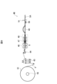
- Figure 9 is a conceptual diagram of a rolling device 60 used in the manufacturing method of heat exchanger 1A.
- the fin forming device 40 does not need to include the rolling rolls 45.
- the uncoiler 42 holds a coil 61 around which a strip-shaped plate member 5 having a thick plate portion 35 and a thin plate portion 36 is wound, and the plate member 5 pulled out from the coil 61 is passed around the dancer roll 43 and then between multiple pairs of forming rolls 46 without passing through the rolling rolls 45.
- the coil 61 may be manufactured by the rolling device 60 shown in FIG. 9. This is because even with this modified example of the fin forming device 40, the fin 3A can be manufactured from the strip-shaped plate member 5 having the thick plate portion 35 and the thin plate portion 36.
- the rolling device 60 refers to a device equipped with a means for rolling the strip metal plate 4, for example, the rolling rolls 45.
- the rolling device 60 is a device equipped with an uncoiler 62 that supports the core portion of the coil 41 around which the strip metal plate 4 is wound, a plurality of dancer rolls 63 that maintain a constant tension in the strip metal plate 4 pulled out from the uncoiler 62, a plurality of sets of rolling rolls 65 having the same configuration as the plurality of sets of rolling rolls 45 described in the first embodiment, and a recoiler 66 that winds the strip plate member 5 produced by rolling with the rolling rolls 65 into the coil 61.
- the thick plate portions 35 of the fins 3A are rectangular in cross section, and as a result, the corners of the protrusions 37, 38 are right angles in cross section.
- the cross-sectional shape of the protrusions 37, 38 is not limited to this.
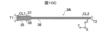
- FIGS. 10A to 10C are cross-sectional views of first to third modified examples of the fins 3A provided in the heat exchanger 1A.
- the front end of the thick plate portion 35 i.e., the +Y end
- the corners of the protrusions 37 and 38 on the +Y side in cross section are rounded.
- the -Y end of the thin plate portion 36 is rounded, so that the corners of the thin plate portion 36 on the -Y side in cross section are rounded.
- Such a shape is formed by using a roll that presses the width direction end of the strip metal plate 4 when rolling the strip metal plate 4 with the above-mentioned rolling roll 45, or by providing a guide mechanism on the rolling roll 45 that presses the width direction end.
- the corners of the protrusions 37 and 38 in cross section may be rounded in addition to being right-angled.
- the corners of the protrusions 37 and 38 in cross section may be chamfered.
- thick plate portion 35 in the third modified example of fin 3A, a recess is formed in thick plate portion 35, so that thick plate portion 35 does not have a constant thickness, but has multiple thicknesses. In this way, thick plate portion 35 may have multiple thicknesses as a result of the thickness varying in the extension direction.
- the +Y end portion of fin 3A protrudes beyond heat transfer tube 2 in the +Y direction, which is the downwind side shown in FIG. 4, and thick plate portion 35 is formed only on this protruding portion 30.
- thick plate portion 35 is formed on the part of protruding portion 30 away from heat transfer tube 2.
- the position of thick plate portion 35 is not limited to this.
- FIG. 11A is a cross-sectional view of a fourth modified example of the fin 3A of the heat exchanger 1A.
- FIG. 11B is a cross-sectional view taken along the XIB-XIB cutting line shown in FIG. 11A.
- a thick plate portion 35 is formed from the protruding portion 30 of the fin 3A that protrudes in the -Y direction beyond the heat transfer tubes 2 to the portion sandwiched between the heat transfer tubes 2.
- the base portion of the thick plate portion 35 i.e., the region A1 portion
- the region A1 portion of the thick plate portion 35 is brazed to the heat transfer tube 2.
- the thick plate portion 35 not only increases the strength and rigidity of the protruding portion 30, but also increases the strength and rigidity of the heat exchanger 1A itself.
- the thick plate portion 35 is formed not only in the protruding portion 30 of the fin 3A, but also in the portion of the fin 3A from the protruding portion 30 to the portion sandwiched between the heat transfer tubes 2.
- the +Y end of the fin 3A does not protrude further in the +Y direction than the heat transfer tube 2, and is in the same position in the Y direction as the +Y end of the heat transfer tube 2.
- a thick plate portion 35 is formed from the +Y end of the fin 3A to the portion sandwiched between the heat transfer tubes 2. In this case, too, the thick plate portion 35 is joined to the heat transfer tube 2, thereby increasing the strength and rigidity of the heat exchanger 1A itself.
- the thin plate portion 36 may be provided with projections and recesses.
- the protruding portion 30 is provided on the -Y side of the fin 3A, but the protruding portion 30 may be provided on the +Y side of the fin 3A.
- one thick plate portion 35 is provided at the +Y end portion of the fin 3A.
- the fin 3A is not limited to this.
- the fin 3A may have a thick plate portion 35 and a thin plate portion 36 that is thinner than the thick plate portion 35 and adjacent to the thick plate portion 35, and at least one plate surface may be uneven due to the thick plate portion 35 and the thin plate portion 36 being adjacent to each other. Therefore, the fin 3A may have a plurality of thick plate portions 35.
- the thick plate portion 35 may be provided at a portion other than the +Y end portion of the fin 3A.
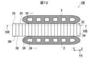
- FIG. 12 is an enlarged top view of some of the fins 3B provided in the heat exchanger 1B according to the second embodiment.
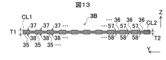
- FIG. 13 is a cross-sectional view taken along the XIII-XIII cutting line shown in FIG. 12. Note that in FIG. 12, the cut-and-raised portion 39 is omitted for ease of understanding. Also, like FIG. 5, FIG. 13 shows a cross-section of only the uppermost portion of the corrugated fin 3B when it is extracted and unfolded.
- the fin 3B has thick plate portions 35 and thin plate portions 36 arranged alternately.
- the fin 3B has convex portions 37, 38 and concave portions 57, 58 on each plate surface.
- the fin 3B has thick plate portions 35 and thin plate portions 36 arranged alternately in the order of thick plate portion 35 and thin plate portion 36 from the +Y end.
- the +Z surface of the fin 3B has convex portions 37 and concave portions 57 arranged alternately.
- the -Z surface of the fin 3B also has convex portions 38 and concave portions 58 arranged alternately.
- the distance between adjacent convex portions 37 or adjacent convex portions 38, i.e., the pitch of the convex portions 37 or 38, is, for example, 1 mm or more.
- the fin 3B has increased strength and rigidity due to having such a configuration.
- the difference in thickness between the thick plate portion 35 and the thin plate portion 36 should be large enough that when the fin 3B is abutted against the heat transfer tube 2 and brazed, the solder penetrates into the recesses 57, 58 of the thin plate portion 36, or a solder fillet is formed.
- the +Y end portion of the fin 3B protrudes further in the +Y direction than the heat transfer tube 2.
- the +Y end portion of the fin 3B is provided with a plurality of thick plate portions 35.
- the thick plate portion 35 and the thin plate portion 36 extend in the direction in which the peak portions 31 and valley portions 33 described in the first embodiment of the corrugated shape of the fin 3B join together. This allows the thick plate portion 35 and the thin plate portion 36 to be provided over the entire fin 3B. As a result, the thick plate portion 35 and the thin plate portion 36 increase the strength and rigidity of the entire fin 3B, and prevent deformation of the corrugation of the entire fin 3B.
- the manufacturing method of the heat exchanger 1B according to the second embodiment is the same as that of the first embodiment, except that the fins 3B are manufactured by using a rolling roll (not shown) having concave and convex portions arranged alternately in the axial direction on its outer periphery, instead of the rolling roll 45 described in the first embodiment. For this reason, a detailed description of the manufacturing method of the heat exchanger 1B is omitted.
- the thick plate portion 35 and the thin plate portion 36 are provided over the entire fin 3B. Therefore, the strength and rigidity of the entire fin 3B are high, and the fin 3B is less likely to deform.
- the thick plate portions 35 and the thin plate portions 36 are arranged alternately, so the strength and rigidity of the fin 3B are higher than when the entire fin 3B is made thin. Also, the fin 3B can be manufactured using less material than when the entire fin 3B remains thick, so the material cost of the fin 3B is lower.
- the cut-and-raised portions 39 are provided in the portion of the fin 3B where the thick plate portions 35 and thin plate portions 36 are alternately arranged.
- the fin 3B is not limited to this.
- the fin 3B may be provided with an area where the thick plate portions 35 and thin plate portions 36 are not formed, and the cut-and-raised portions 39 may be provided in this area. This is because in this embodiment, the cut-and-raised portions 39 are easier to fabricate, and the cut-and-raised portions 39 can be fabricated with high precision.
- one thick plate portion 35 is provided at one end portion of fin 3A.
- fins 3A and 3B are provided with thick plate portion 35, so that convex portion 37 is provided on one side of fins 3A and 3B, and convex portion 38 is provided on the other side of fins 3A and 3B.
- fins 3A and 3B are not limited to this. Fins 3A and 3B may have thick plate portion 35 and thin plate portion 36 that is thinner than thick plate portion 35 and adjacent to thick plate portion 35, and at least one plate surface may be uneven due to the thick plate portion 35 and thin plate portion 36 being adjacent to each other.
- FIGS. 14A-14E are partial cross-sectional views of the first to fifth modified thick plate sections 35 provided on the fins 3A of the heat exchanger 1A according to embodiment 1.
- FIGS. 15A-15F are partial cross-sectional views of the sixth to eleventh modified thick plate sections 35 provided on the fins 3A.
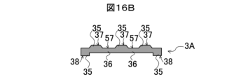
- FIGS. 16A and 16B are partial cross-sectional views of the twelfth and thirteenth modified thick plate sections 35 provided on the fins 3A.
- a thick plate section 35 may be provided in the center of the fin 3A, and thin plate sections 36 may be provided at both ends.
- convex sections 37 and 38 may be provided on each plate surface of the fin 3A
- concave sections 57 and 58 may be provided on each plate surface of the fin 3A.
- convex section 37 and concave section 57 may be provided on only one plate surface of the fin 3A.
- thick plate sections 35 may be provided at both ends of fin 3A, and thin plate section 36 may be provided in the center of fin 3A.
- protrusions 37 and 38 may be provided on each plate surface of fin 3A, and recesses 57 and 58 may be provided on each plate surface of fin 3A.
- protrusions 37 and recesses 57 may be provided on only one plate surface of fin 3A.
- thick plate sections 35 and thin plate sections 36 may be provided alternately, and convex sections 37 and concave sections 57 may be provided on only one plate surface of the fin 3A.
- the end faces of the thick plate portion 35 may be inclined, so that the convex portions 37 and 38 are trapezoidal in cross section.
- the end faces of the thick plate portion 35 may be inclined and the width of the thick plate portion 35 may be minute, so that the convex portions 37 and 38 are triangular in cross section.
- the end faces of the thick plate portion 35 may be arc-shaped in cross section, more specifically semicircular in cross section, so that the convex portions 37 and 38 are semicircular or semielliptical in cross section.
- the fin 3A in addition to the thick plate portion 35 and the thin plate portion 36, the fin 3A may have a thick plate portion 59 that is thinner than the thick plate portion 35 and thicker than the thin plate portion 36, so that the width of the protrusion 37 on one plate surface of the fin 3A and the width of the protrusion 38 on the other plate surface of the fin 3A may be different.
- the protrusions 37 and 38 may be square.
- the protrusion 37 may be trapezoidal in cross section, and the protrusion 38 may be rectangular in cross section.
- the protrusion 37 may be rectangular in cross section, and the protrusion 38 may be trapezoidal in cross section.
- FIG. 16A in addition to the thick plate portion 35 and the thin plate portion 36, the fin 3A may have a thick plate portion 59 that is thinner than the thick plate portion 35 and thicker than the thin plate portion 36, so that the width of the protrusion 37 on one plate surface of the fin 3A and the width of the protrusion 38 on the other plate surface of the fin
- the thick plate portion 35 may form only the protrusion 37 on one plate surface or only the protrusion 38 on the other plate surface.
- the protrusion 37 may be trapezoidal in cross section, and the protrusion 38 may be rectangular in cross section.
- the protrusion 37 may be rectangular in cross section, and the protrusion 38 may be trapezoidal in cross section.
- thick plate sections 35 and thin plate sections 36 are alternately formed in the fin 3B.
- a combination of thick plate sections 35 and thin plate sections 36 adjacent to the thick plate sections 35 is formed throughout the fin 3B.
- the arrangement of the thick plate sections 35 and thin plate sections 36 is not limited to this.
- the thick plate sections 35 and thin plate sections 36 are adjacent to each other, so that unevenness is formed on at least one plate surface.
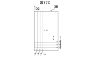
- FIGS. 17A-17E are conceptual diagrams of first to fifth modified examples of the arrangement patterns of the thick plate sections 35 and thin plate sections 36 provided on the fin 3B of the heat exchanger 1B according to the second embodiment.
- FIGS. 17A-17E show the fin 3B when the corrugation is expanded in a straight line.
- the longitudinal direction of the fin 3B is the feed direction D2 in which the plate member 5 of the fin forming device 40 shown in FIG. 7 is fed into the forming roll 46.
- the irregularities 7-10 formed by the combination of the thick plate sections 35 and thin plate sections 36 described in FIGS. 13(A)-13(F) and 16A and 16B are shown as solid lines.
- the parts of the fin 3B without solid lines are flat surfaces without the irregularities 7-10.
- the fin 3B may have a plurality of irregularities 7 that extend in the longitudinal direction and are arranged in the lateral direction. Also, as shown in FIG. 17B, the fin 3B may have a plurality of irregularities 8 that extend in the lateral direction and are arranged in the longitudinal direction. Furthermore, as shown in FIG. 17C, the fin 3B may have a mixture of a plurality of irregularities 7 that extend in the longitudinal direction and are arranged in the lateral direction, and a plurality of irregularities 8 that extend in the lateral direction and are arranged in the longitudinal direction.
- the longitudinal direction of the fin 3B refers to the longitudinal direction of the fin 3B when it is unfolded into a flat plate, and is the direction in which the heat transfer tubes 2 are arranged in the heat exchanger 1B.
- the transverse direction of the fin 3B refers to the transverse direction of the fin 3B when it is unfolded into a flat plate, and is the direction perpendicular to the direction in which the heat transfer tubes 2 are arranged in the heat exchanger 1B.
- the fin 3B may have a plurality of projections and recesses 9 that extend in a direction inclined relative to the longitudinal direction of the fin 3B and are parallel to each other.
- the fin 3B may also have a plurality of projections and recesses 10 that are inclined in different directions relative to the longitudinal direction.
- the fin 3B may have a plurality of projections and recesses 9 that are inclined at a certain angle relative to the longitudinal direction, and a plurality of projections and recesses 10 that are inclined linearly symmetrically to the plurality of projections and recesses 9.
- the fins 3A and 3B have a corrugated shape.
- the fins 3A and 3B have the above-mentioned thick plate portion 35 and the thin plate portion 36 that is thinner than the thick plate portion 35 and adjacent to the thick plate portion 35, and as long as the condition that at least one plate surface is uneven due to the thick plate portion 35 and the thin plate portion 36 being adjacent to each other is satisfied, the overall shape is arbitrary as long as this condition is satisfied.
- the fins 3A and 3B may be flat overall.
- the heat transfer tube 2 is flat, but the shape of the heat transfer tube 2 is arbitrary.
- the heat transfer tube 2 may be, for example, a circular tube.
- the heat exchangers 1A and 1B and the manufacturing method for the heat exchangers 1A and 1B are not limited to the above-described embodiment, and various modifications and substitutions can be made.
- Various embodiments of the present disclosure are described below as appendices.
- the protruding portion of the fin is provided with both the thick plate portion and the thin plate portion. 2.
- the heat exchanger of claim 1. (Appendix 3) The thick plate portion is provided from the protruding portion to a portion sandwiched between the fins, and is joined to the fin at the portion sandwiched between the fins. 2.
- the heat exchanger of claim 1. (Appendix 4) The thick plate portion protrudes from the thin plate portion in a quadrangular shape that is rectangular or trapezoidal in cross-sectional view. 4.
- the heat exchanger of claim 1. (Appendix 5) The thick plate portion protrudes from the thin plate portion in a triangular shape in a cross-sectional view. 4. The heat exchanger of claim 1.
- the fin has a corrugated shape in which peaks and valleys are connected in the tube axis direction. 10.
- the heat exchanger of any one of claims 1 to 9. (Appendix 11) a rolling process for producing a fin plate member having a thick plate portion and a thin plate portion adjacent to the thick plate portion, the thin plate portion being thinner than the thick plate portion and adjacent to the thick plate portion, by sandwiching a metal plate between a pair of rolls, at least one of which has a convex portion and a concave portion adjacent to the convex portion on an outer peripheral surface, the fin plate member having the thick plate portion and the thin plate portion, at least one plate surface being uneven and the thick plate portion being formed at an end portion; a fin forming step of forming a corrugated fin from the fin plate member; a step of arranging a plurality of heat transfer tubes in a direction perpendicular to the tube axes with the tube axes oriented parallel to each other, and assembling the fins to the heat transfer tubes by sandwich
- a method for manufacturing a heat exchanger In the rolling step, the pair of rolls rolls the metal plate to form the fin plate member having minute linear grooves, The minute linear grooves extend in a feed direction in which the pair of rolls feed the metal plate by rotation.
- a method for manufacturing a heat exchanger according to claim 11. (Appendix 13) The metal plate has a strip shape, In the rolling step, the metal plate is rolled in a direction in which the band of the metal plate extends in a feed direction in which the pair of rolls rotate to feed the metal plate, thereby producing the band-shaped fin plate member, In the fin forming step, the fin plate member is bent in a direction in which the band extends to produce the corrugated fin. 13.
Landscapes
- Engineering & Computer Science (AREA)
- Physics & Mathematics (AREA)
- Thermal Sciences (AREA)
- Mechanical Engineering (AREA)
- General Engineering & Computer Science (AREA)
- Geometry (AREA)
- Heat-Exchange Devices With Radiators And Conduit Assemblies (AREA)
Priority Applications (1)
| Application Number | Priority Date | Filing Date | Title |
|---|---|---|---|
| JP2025510663A JP7847718B2 (ja) | 2023-03-28 | 2024-03-21 | 熱交換器および熱交換器の製造方法 |
Applications Claiming Priority (2)
| Application Number | Priority Date | Filing Date | Title |
|---|---|---|---|
| JP2023051942 | 2023-03-28 | ||
| JP2023-051942 | 2023-03-28 |
Publications (1)
| Publication Number | Publication Date |
|---|---|
| WO2024203755A1 true WO2024203755A1 (ja) | 2024-10-03 |
Family
ID=92906177
Family Applications (1)
| Application Number | Title | Priority Date | Filing Date |
|---|---|---|---|
| PCT/JP2024/011115 Ceased WO2024203755A1 (ja) | 2023-03-28 | 2024-03-21 | 熱交換器および熱交換器の製造方法 |
Country Status (2)
| Country | Link |
|---|---|
| JP (1) | JP7847718B2 (https=) |
| WO (1) | WO2024203755A1 (https=) |
Citations (5)
| Publication number | Priority date | Publication date | Assignee | Title |
|---|---|---|---|---|
| JPS5455756U (https=) * | 1977-09-22 | 1979-04-18 | ||
| JPH0525171U (ja) * | 1991-09-12 | 1993-04-02 | 東洋運搬機株式会社 | ラジエータ |
| JP2002147982A (ja) * | 2000-11-10 | 2002-05-22 | Toyo Radiator Co Ltd | コルゲートフィン型熱交換器およびその製造方法 |
| US20060131006A1 (en) * | 2004-12-17 | 2006-06-22 | Viktor Brost | Heat exchanger and ribs |
| JP2010181140A (ja) * | 2009-01-15 | 2010-08-19 | Valeo Systemes Thermiques | 熱交換器用の熱交換インサート |
-
2024
- 2024-03-21 JP JP2025510663A patent/JP7847718B2/ja active Active
- 2024-03-21 WO PCT/JP2024/011115 patent/WO2024203755A1/ja not_active Ceased
Patent Citations (5)
| Publication number | Priority date | Publication date | Assignee | Title |
|---|---|---|---|---|
| JPS5455756U (https=) * | 1977-09-22 | 1979-04-18 | ||
| JPH0525171U (ja) * | 1991-09-12 | 1993-04-02 | 東洋運搬機株式会社 | ラジエータ |
| JP2002147982A (ja) * | 2000-11-10 | 2002-05-22 | Toyo Radiator Co Ltd | コルゲートフィン型熱交換器およびその製造方法 |
| US20060131006A1 (en) * | 2004-12-17 | 2006-06-22 | Viktor Brost | Heat exchanger and ribs |
| JP2010181140A (ja) * | 2009-01-15 | 2010-08-19 | Valeo Systemes Thermiques | 熱交換器用の熱交換インサート |
Also Published As
| Publication number | Publication date |
|---|---|
| JP7847718B2 (ja) | 2026-04-17 |
| JPWO2024203755A1 (https=) | 2024-10-03 |
Similar Documents
| Publication | Publication Date | Title |
|---|---|---|
| CN108139179B (zh) | 用于板式换热器的翅片及其制造方法 | |
| US8516699B2 (en) | Method of manufacturing a heat exchanger having a contoured insert | |
| US12392562B2 (en) | Indirect heat exchanger pressure vessel with controlled wrinkle bends | |
| WO2011105369A1 (ja) | コルゲートフィンおよびそれを備える熱交換器 | |
| US20110247794A1 (en) | Flattened tubes for use in heat exchangers and other systems, and associated methods of manufacture and use | |
| JPH03155422A (ja) | 熱交換器用伝熱管及びその製造方法 | |
| JP7766785B2 (ja) | 熱交換器および熱交換器の製造方法 | |
| US8732952B2 (en) | Heat exchanger fin with ribbed hem | |
| WO2024203755A1 (ja) | 熱交換器および熱交換器の製造方法 | |
| EP2085733A1 (en) | Heat exchanger tube and method of producing the same | |
| US20070235172A1 (en) | Heat transferring member and heat exchanger having the same | |
| JP3311001B2 (ja) | 熱交換器用チューブの製造方法 | |
| EP2106520B1 (en) | Heat exchanger fin | |
| JP3966072B2 (ja) | 熱交換器用チューブの製造方法 | |
| JP2915660B2 (ja) | 熱交換器用チューブ及び製造方法 | |
| JP5167930B2 (ja) | 熱交換器 | |
| JP4599732B2 (ja) | 複式熱交換器の製造方法 | |
| JP7788862B2 (ja) | 熱交換器の製造方法および空気調和機の製造方法 | |
| WO2000031486A1 (fr) | Tubes d'echangeurs de chaleur rainures interieurement et rouleau d'usinage de barres de metal servant a produire lesdits tubes | |
| JP2020099936A (ja) | ハニカム構造体の製造方法 | |
| JP2007107755A (ja) | 熱交換器、熱交換器用チューブ、およびそれらの製造方法 | |
| JP4467106B2 (ja) | 熱交換器用チューブ及びその製造方法 | |
| JP2868163B2 (ja) | 熱交換器用伝熱管の製造方法 | |
| JP2002168581A (ja) | 複式熱交換器 | |
| WO2008103502A1 (en) | Heat exchanger, method of manufacturing a heat exchanger, and roller train for manufacturing heat exhanger tubes |
Legal Events
| Date | Code | Title | Description |
|---|---|---|---|
| 121 | Ep: the epo has been informed by wipo that ep was designated in this application |
Ref document number: 24779874 Country of ref document: EP Kind code of ref document: A1 |
|
| WWE | Wipo information: entry into national phase |
Ref document number: 2025510663 Country of ref document: JP |
|
| NENP | Non-entry into the national phase |
Ref country code: DE |
|
| 122 | Ep: pct application non-entry in european phase |
Ref document number: 24779874 Country of ref document: EP Kind code of ref document: A1 |