WO2024203056A1 - 光学素子および画像投影装置 - Google Patents
光学素子および画像投影装置 Download PDFInfo
- Publication number
- WO2024203056A1 WO2024203056A1 PCT/JP2024/008451 JP2024008451W WO2024203056A1 WO 2024203056 A1 WO2024203056 A1 WO 2024203056A1 JP 2024008451 W JP2024008451 W JP 2024008451W WO 2024203056 A1 WO2024203056 A1 WO 2024203056A1
- Authority
- WO
- WIPO (PCT)
- Prior art keywords
- light
- optical element
- reflecting surface
- incident
- prism
- Prior art date
- Legal status (The legal status is an assumption and is not a legal conclusion. Google has not performed a legal analysis and makes no representation as to the accuracy of the status listed.)
- Ceased
Links
Images











Classifications
-
- B—PERFORMING OPERATIONS; TRANSPORTING
- B60—VEHICLES IN GENERAL
- B60K—ARRANGEMENT OR MOUNTING OF PROPULSION UNITS OR OF TRANSMISSIONS IN VEHICLES; ARRANGEMENT OR MOUNTING OF PLURAL DIVERSE PRIME-MOVERS IN VEHICLES; AUXILIARY DRIVES FOR VEHICLES; INSTRUMENTATION OR DASHBOARDS FOR VEHICLES; ARRANGEMENTS IN CONNECTION WITH COOLING, AIR INTAKE, GAS EXHAUST OR FUEL SUPPLY OF PROPULSION UNITS IN VEHICLES
- B60K35/00—Instruments specially adapted for vehicles; Arrangement of instruments in or on vehicles
- B60K35/20—Output arrangements, i.e. from vehicle to user, associated with vehicle functions or specially adapted therefor
- B60K35/21—Output arrangements, i.e. from vehicle to user, associated with vehicle functions or specially adapted therefor using visual output, e.g. blinking lights or matrix displays
- B60K35/23—Head-up displays [HUD]
-
- B—PERFORMING OPERATIONS; TRANSPORTING
- B60—VEHICLES IN GENERAL
- B60R—VEHICLES, VEHICLE FITTINGS, OR VEHICLE PARTS, NOT OTHERWISE PROVIDED FOR
- B60R11/00—Arrangements for holding or mounting articles, not otherwise provided for
- B60R11/02—Arrangements for holding or mounting articles, not otherwise provided for for radio sets, television sets, telephones, or the like; Arrangement of controls thereof
-
- G—PHYSICS
- G02—OPTICS
- G02B—OPTICAL ELEMENTS, SYSTEMS OR APPARATUS
- G02B27/00—Optical systems or apparatus not provided for by any of the groups G02B1/00 - G02B26/00, G02B30/00
- G02B27/01—Head-up displays
-
- G—PHYSICS
- G02—OPTICS
- G02B—OPTICAL ELEMENTS, SYSTEMS OR APPARATUS
- G02B5/00—Optical elements other than lenses
- G02B5/04—Prisms
-
- H—ELECTRICITY
- H04—ELECTRIC COMMUNICATION TECHNIQUE
- H04N—PICTORIAL COMMUNICATION, e.g. TELEVISION
- H04N5/00—Details of television systems
- H04N5/64—Constructional details of receivers, e.g. cabinets or dust covers
Definitions
- This disclosure relates to an optical element and an image projection device including the optical element.
- Patent Document 1 discloses a head-up display (HUD) that projects light that becomes a virtual image emitted from an image generation unit onto a windshield using an optical system, and reflects the light off the windshield to superimpose the virtual image onto the real space in front of the vehicle.
- HUD head-up display
- a single image generation unit is used to form virtual images that appear close and virtual images that appear far away.
- a head-up display that forms such near and far virtual images, it is being considered to generate a first image light that becomes a near virtual image and a second image light that becomes a far virtual image by an image generating unit, and to create a difference in the optical path length between the two by using a reflecting prism.
- the inventors have investigated ways to mitigate the problem of temperature rise caused by external light in image projection devices that use optical elements such as prisms by using optical elements.
- One of the objectives of this disclosure is to provide an optical element that can suppress the problem of temperature rise caused by external light in an image projection device, and an image projection device equipped with the optical element.
- optical elements such as reflecting prisms tend to be large, and dimensional control can become difficult due to cooling during molding.
- One of the objectives of this disclosure is to improve the moldability of optical elements used in image projection devices.
- One of the objectives of this disclosure is to miniaturize image projection devices.
- the optical element comprises: an incidence surface on which light is incident; an exit surface opposite to the entrance surface; a first reflecting surface that reflects light incident on the incident surface; a second reflecting surface facing the first reflecting surface and reflecting the light reflected by the first reflecting surface toward the exit surface, One of the first reflecting surface and the second reflecting surface is configured to totally reflect light; The other of the first reflecting surface and the second reflecting surface is provided with a reflective polarizing portion that reflects light in a predetermined vibration direction.
- An image projection device includes: An image projection device for projecting an image, comprising: an image generating unit that generates light forming the image; The optical element for controlling the light; It is equipped with:
- the optical element comprises: an incidence surface on which the first light and the second light are incident; an exit surface facing the entrance surface and from which the first light and the second light exit; a first reflecting surface that reflects the second light incident from the incident surface; a second reflecting surface facing the first reflecting surface and configured to reflect the second light reflected by the first reflecting surface toward the exit surface; A light blocking portion is disposed on at least one of the entrance surface and the exit surface and extends into the interior of the optical element.
- the optical element comprises: an incidence surface on which the first light and the second light are incident; an exit surface facing the entrance surface and from which the first light and the second light exit; a first reflecting surface that reflects the second light incident from the incident surface; a second reflecting surface facing the first reflecting surface and reflecting the second light reflected by the first reflecting surface toward the exit surface, The first reflecting surface and the second reflecting surface are divided in the opposing direction.
- An image projection device includes: The optical element described above, an image generating unit that emits the first light and the second light to the optical element; Equipped with the optical element includes a first optical element and a second optical element that are divided in a direction in which the first reflecting surface and the second reflecting surface face each other, the first optical element is bonded to the second optical element; a first optical path of the first light extends substantially parallel to a surface of the first optical element bonded to the second optical element; A second optical path of the second light extends substantially perpendicular to a surface of the first optical element bonded to the second optical element.
- An image projection device includes: an image generating unit that emits a first light that becomes a first virtual image and a second light that becomes a second virtual image; an optical element for controlling the first light and the second light; Equipped with The optical element is an incident surface onto which the first light and the second light are incident; an exit surface facing the entrance surface and from which the first light and the second light exit; a first reflecting surface that reflects the second light incident from the incident surface; a second reflecting surface facing the first reflecting surface and reflecting the second light reflected by the first reflecting surface toward the exit surface; having An angle ⁇ 1 between the incident surface and the first reflecting surface is smaller than an angle ⁇ 2 between the second reflecting surface and the exit surface.
- An image projection device includes: an image generating unit that emits a first light that becomes a first virtual image and a second light that becomes a second virtual image; an incident surface onto which the first light and the second light are incident; an exit surface facing the entrance surface and from which the first light and the second light exit; a first reflecting surface that reflects the second light incident from the incident surface; an optical element having a second reflecting surface facing the first reflecting surface and reflecting the second light reflected by the first reflecting surface toward the exit surface; The optical element further includes a light-shielding portion disposed near the exit surface of the optical element so as to separate an optical path of the first light emitted from the exit surface from an optical path of the second light.
- the present disclosure provides an optical element that can suppress the problem of temperature rise caused by external light in an image projection device, and an image projection device equipped with the optical element.
- this disclosure makes it possible to improve the moldability of optical elements used in image projection devices.
- this disclosure allows the image projection device to be made smaller.
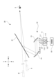
- FIG. 1 is a schematic diagram illustrating a configuration of a head-up display (HUD) according to an embodiment of the present invention.
- 3 is a perspective view illustrating the configuration of a prism according to the first embodiment.
- FIG. 4 is a cross-sectional view illustrating an example of a prism configuration.
- FIG. 1A and 1B are diagrams for explaining the influence of external light entering a prism.
- FIG. 11 is a cross-sectional view illustrating another configuration of the HUD. 6 is a diagram for explaining the influence of external light incident on the prism in FIG. 5 .
- FIG. 11 is a cross-sectional view illustrating another configuration of the HUD.
- 11A and 11B are cross-sectional views illustrating examples of other configurations of the prism.
- 11A and 11B are cross-sectional views illustrating examples of other configurations of the prism.
- 6 is a cross-sectional view illustrating the configuration of a prism according to a second embodiment.
- FIG. FIG. 11 is a bottom view of the prism in FIG. 10.
- FIG. 11 is a top view of the prism of FIG. 10.
- 11A and 11B are cross-sectional views illustrating examples of other configurations of the prism.
- FIG. 14 is a top view of the prism of FIG. 13.
- 11A and 11B are cross-sectional views illustrating examples of other configurations of the prism.
- 13A and 13B are top views illustrating alternative configurations of the prism.
- 11A and 11B are cross-sectional views illustrating examples of other configurations of the prism.
- FIG. 11 is a perspective view illustrating the configuration of a prism according to a third embodiment. 19 is a cross-sectional view illustrating the configuration of the prism in FIG. 18. 11A and 11B are cross-sectional views illustrating examples of other configurations of the prism.
- FIG. 13 is a perspective view illustrating the configuration of a prism according to a fourth embodiment. 22 is a cross-sectional view illustrating the configuration of the prism in FIG. 21. 11 is a cross-sectional view illustrating a configuration of a prism in which ⁇ 1 and ⁇ 2 are the same.
- FIG. 24 is a diagram for explaining the optical path of a first light beam and the optical path of a second light beam emitted from the prism in FIG. 23 .
- FIG. 24 is a diagram for explaining the optical path of a first light beam and the optical path of a second light beam emitted from the prism in FIG. 23 .
- FIG. 24 is a diagram for explaining the optical path of a first light beam
- FIG. 23 is a diagram for explaining the optical path of a first light beam and the optical path of a second light beam emitted from the prism in FIG. 22.
- 11 is a diagram showing optical paths when a first light and a second light are emitted in directions away from each other from an image generating unit.
- FIG. 4 is a diagram for explaining optical paths of a first light and a second light propagating through a prism.
- FIG. 1A and 1B are cross-sectional views illustrating configurations of prisms tilted relative to an image generation surface.
- FIG. 29 is a light path diagram when the first light and the second light are emitted in directions away from each other from the image generation surface in the arrangement configuration of FIG. 28 .
- FIG. 11 is a cross-sectional view illustrating a configuration of a prism in which a second optical path of a second light beam extends substantially parallel to the entrance surface and the exit surface.
- FIG. FIG. 13 is a schematic diagram illustrating the configuration of a HUD according to a fifth embodiment.
- 32 is a cross-sectional view illustrating the configuration of the prism in FIG. 31.
- FIG. 32 is a top view of the prism in FIG. 31.
- 11 is a cross-sectional view illustrating a configuration of a HUD in which a light blocking portion is separated from a prism.
- 1 is a cross-sectional view illustrating a configuration of a HUD in which a part of a light blocking portion is embedded in a prism.
- 13A and 13B are cross-sectional views illustrating light blocking portions provided in a prism according to a fourth embodiment.
- FIG. 1 illustrates an example of the configuration of a HUD 10 according to this embodiment.
- the HUD 10 is installed in the cabin of the vehicle 20.
- the HUD 10 is disposed in the dashboard of the vehicle 20.
- the HUD 10 functions as a visual interface between the vehicle 20 and the occupant of the vehicle 20.
- the HUD 10 is configured to display an image showing predetermined information as a virtual image toward the occupant of the vehicle 20 so that the image showing the information is superimposed on the real space outside the vehicle 20 (for example, the surrounding environment in front of the vehicle 20).
- the predetermined information is displayed as a still image or a video (image).
- the HUD 10 is an example of an image projection device.
- HUD 10 includes an image generation unit (PGU: Picture Generation Unit) 11, a prism 12, a concave mirror 13, a concave mirror 14, and a control unit 15.
- the image generation unit 11, the prism 12, the concave mirror 13, the concave mirror 14, and the control unit 15 are disposed in a housing (not shown).
- the image generating unit 11 is configured to generate a predetermined image and emit light that constitutes the image.
- the image generating unit 11 emits the light that constitutes the image polarized in a predetermined vibration direction.
- the image generating unit 11 emits first light L1 that becomes a first virtual image, and emits second light L2 that becomes a second virtual image that appears farther away than the first virtual image.
- the image generating unit 11 has, for example, a light source 111, an optical element 112, and a display device 113.
- the light source 111 is an LED (Light Emitting Diode) light source or a laser light source.
- the optical element 112 emits light emitted from the light source 111 toward the display device 113.
- the optical element 112 is, for example, a lens, a diffuser, a magnifying glass, etc.
- the display device 113 generates a predetermined image using the light emitted from the optical element 112.
- the display device 113 is, for example, a liquid crystal display (LCD).
- the display device 113 may be an organic EL (Electro Luminescence) display, a DMD (Digital Mirror Device), an LCOS (Liquid Crystal On Silicon), or a MEMS (Micro Electro Mechanical Systems).
- organic EL Electro Luminescence
- DMD Digital Mirror Device
- LCOS Liquid Crystal On Silicon
- MEMS Micro Electro Mechanical Systems
- the prism 12 is disposed on the optical path of the light emitted from the image generating unit 11.
- the prism 12 is configured to control the light emitted from the image generating unit 11.
- the prism 12 is configured to control the first light L1 and the second light L2 emitted from the image generating unit 11, and to generate a difference in the optical path length of both the light and the second light.
- the prism 12 controls the first light L1 and the second light L2 so that the optical path length of the first light L1 is shorter than the optical path length of the second light L2.
- the prism 12 is formed of a light-transmitting material. Examples of light-transmitting materials include glass materials and transparent resin materials such as acrylic and polycarbonate. The detailed structure of the prism 12 will be described later.
- the prism 12 is an example of an optical element.
- the concave mirror 13 is disposed on the optical path of the light emitted from the prism 12.
- the concave mirror 13 has a concavely curved reflecting surface.
- the concave mirror 13 is configured to reflect the first light L1 and the second light L2 emitted from the prism 12 toward the concave mirror 14.
- the concave mirror 14 is disposed on the optical path of the light emitted from the concave mirror 13.
- the concave mirror 14 has a concavely curved reflecting surface.
- the concave mirror 14 is configured to reflect the first light L1 and the second light L2 reflected by the concave mirror 13 toward the windshield 21 (front window).
- the optical path of the first light L1 and the optical path of the second light L2 are drawn as a single straight line, but the actual first light L1 and the second light L2 are displayed in a predetermined area in the image generating unit 11 and have a predetermined area in the direction perpendicular to the traveling direction.
- the optical path of the first light L1 and the optical path of the second light L2 may be drawn as a single straight line.
- the concave mirror 13 and the concave mirror 14 may be configured so that the first light L1 and the second light L2 form an intermediate image between the concave mirror 13 and the concave mirror 14.
- the cross-sectional area through which the first light L1 and the second light L2 pass is minimum at the intermediate image position between the concave mirror 13 and the concave mirror 14.
- the optical path of the first light L1 and the optical path of the second light L2 may be configured to intersect at the intersection position between the concave mirror 13 and the concave mirror 14.
- the control unit 15 includes, for example, a general-purpose memory and a general-purpose microprocessor.
- the general-purpose microprocessor operates in cooperation with the general-purpose memory.
- Examples of the general-purpose microprocessor include a CPU, an MPU, and a GPU.
- Examples of the general-purpose memory include a ROM and a RAM.
- the ROM may store a computer program that executes processing for controlling the operation of each unit.
- the general-purpose microprocessor specifies at least a portion of the computer program stored in the ROM, expands it on the RAM, and executes the above-mentioned processing in cooperation with the RAM.
- the control unit 15 is configured to control the operation of each part of the HUD 10.
- the control unit 15 is connected to a vehicle control unit (not shown) that controls the operation of each part of the vehicle 20.
- the control unit 15 generates a control signal for controlling the operation of the image generation unit 11, for example, based on information about the vehicle 20 transmitted from the vehicle control unit.
- the information about the vehicle 20 includes, for example, information about the running state of the vehicle 20, information about the state of the vehicle 20, information about the surrounding environment of the vehicle 20, information about driving assistance for the vehicle 20, and the like.
- the control unit 15 transmits the generated control signal to the image generation unit 11.
- the image generating unit 11 generates images showing predetermined information that are visually recognized as a first virtual image and a second virtual image, respectively, based on a control signal transmitted from the control unit 15.
- the first light L1 and second light L2 constituting the image emitted from the image generating unit 11 propagate within the prism 12, are reflected by the concave mirrors 13 and 14, and are then irradiated onto the windshield 21.
- the first light L1 and second light L2 irradiated onto the windshield 21 are reflected towards the occupant's viewpoint E.
- the occupant recognizes the first light L1 and second light L2 emitted from the HUD 10 as a first virtual image and a second virtual image formed at a predetermined distance in front of the windshield 21.
- the image generated by the image generating unit 11 is superimposed on the real space in front of the vehicle 20 through the windshield 21, and as a result, the occupant can visually recognize the virtual image objects I1 and I2 formed by the first virtual image and the second virtual image as floating above the road located outside the vehicle 20. Because the prism 12 is configured so that the optical path length of the second light L2 is longer than the optical path length of the first light L1, the virtual image object I2 is visually recognized as floating farther away than the virtual image object I1.
- Fig. 2 is a perspective view illustrating the configuration of the prism 12.
- Fig. 3 is a cross-sectional view illustrating the configuration of the prism.
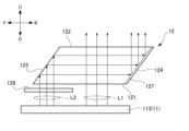
- the prism 12 according to the first embodiment is formed in a parallelepiped shape having an entrance surface 121, an exit surface 122, a first reflecting surface 123, a second reflecting surface 124, a first side surface 125, and a second side surface 126.
- the incident surface 121 is disposed opposite the image generating unit 11 (display device 113) and is configured so that the first light L1 and the second light L2 emitted from the image generating unit 11 are incident thereon.
- the first reflecting surface 123 is configured to reflect the second light L2 incident from the incident surface 121.
- the first reflecting surface 123 is configured to totally reflect the second light L2.
- the first reflecting surface 123 is also configured to reflect the second light L2 toward the second reflecting surface 124 so that the second light L2 propagates within the prism 12 approximately parallel to the incident surface 121.
- the second reflecting surface 124 faces the first reflecting surface 123.
- the second reflecting surface 124 is configured to reflect the second light L2 reflected by the first reflecting surface 123 toward the output surface 122.
- the second reflecting surface 124 is provided with a reflective polarizing film 127 that reflects light in a predetermined vibration direction.
- the reflective polarizing film 127 can be configured so that the vibration direction of the light reflected by the reflective polarizing film 127 is the same as the vibration direction of the second light L2 output from the image generating unit 11.
- the reflective polarizing film 127 is configured from an optical multilayer film or the like, and is bonded to the second reflecting surface 124.
- the reflective polarizing film 127 is an example of a reflective polarizing unit.
- the first side 125 and the second side 126 face each other.
- the first side 125 is adjacent to the first reflecting surface 123 and the second reflecting surface 124.
- the second side 126 is adjacent to the first reflecting surface 123 and the second reflecting surface 124.
- the exit surface 122 faces the entrance surface 121.
- the exit surface 122 is configured to emit the first light L1 and the second light L2 that have propagated within the prism 12.
- the first light L1 emitted from the image generating unit 11 enters the incident surface 121 at a substantially right angle, propagates through the prism 12 toward the exit surface 122, and exits from the exit surface 122 without being reflected by the first reflecting surface 123 and the second reflecting surface 124.
- the second light L2 emitted from the image generating unit 11 is emitted from a position different from the position from which the first light L1 is emitted.
- the second light L2 is incident on the incident surface 121 at a substantially right angle or obliquely, and is incident on the first reflecting surface 123 at an angle at which it is totally reflected.
- the second light L2 is reflected by the first reflecting surface 123 toward the second reflecting surface 124.
- the second light L2 that reaches the second reflecting surface 124 is reflected toward the exit surface 122 by the reflective polarizing film 127 provided on the second reflecting surface 124.
- the vibration direction of the light reflected by the reflective polarizing film 127 is the same as the vibration direction of the second light L2 emitted from the image generating unit 11, the second light L2 is reflected by the reflective polarizing film 127 and exits from the exit surface 122.
- the prism 12 according to this embodiment can prevent external light L10 that enters the prism 12 from propagating within the prism 12, being reflected by the second reflecting surface 124 and the first reflecting surface 123, and entering the image generating unit 11. Therefore, the HUD 10 including the prism 12 according to the first embodiment can prevent degradation of the quality of the second virtual image while suppressing the occurrence of heat damage in the image generating unit 11 caused by external light.
- the configuration of the prism 12 can suppress the occurrence of heat damage caused by external light without the need for additional optical elements such as shades, so there is no need for parts specifically designed to prevent melting damage caused by external light, and this prevents an increase in the number of parts and size.
- the vibration direction of the light reflected by the reflective polarizing film 127 is the same as the vibration direction of the light emitted from the image generating unit 11, but the reflective polarizing film 127 may be configured so that the vibration direction of the light reflected by the reflective polarizing film 127 is close to the vibration direction of the light emitted from the image generating unit 11 to an extent that does not significantly degrade the quality of the second virtual image.
- the reflective polarizing film 127 may be configured to reflect visible light and transmit light with wavelengths in the infrared region. Such a reflective polarizing film 127 does not reflect infrared light contained in external light L10, further reducing the occurrence of heat damage in the image generating unit 11 caused by external light. On the other hand, by using visible light for the second light L2 emitted from the image generating unit 11, deterioration in the quality of the second virtual image can be prevented.
- the HUD 10 may have a polarizing film on the outside of the prism 12.
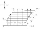
- a polarizing film 128 may be disposed between the image generating unit 11 and the prism 12.
- the polarizing film 128 may be configured with an optical multilayer film or the like.
- the polarizing film 128 is configured so that the vibration direction of the light passing through the polarizing film 128 is the same as the vibration direction of the second light L2 emitted from the image generating unit 11.
- the vibration direction of the light passing through the polarizing film 128 is the same as the vibration direction of the second light L2 emitted from the image generating unit 11, but the polarizing film 128 may be configured so that the vibration direction of the light passing through the polarizing film 128 is close to the vibration direction of the second light L2 emitted from the image generating unit 11 to an extent that does not significantly degrade the quality of the second virtual image.
- a polarizing film 128 may be placed on the optical path of the second light L2 emitted from the exit surface 122 of the prism 12.
- the polarizing film 128 may be configured so that the vibration direction of the light passing through the polarizing film 128 is the same as the vibration direction of the second light L2 reflected by the reflective polarizing film 127.
- the vibration direction of the light passing through the polarizing film 128 is the same as the vibration direction of the light reflected by the reflective polarizing film 127
- the second light L2 reflected by the reflective polarizing film 127 and emitted from the prism 12 passes through the polarizing film 128.
- the external light L10 attempting to enter the prism 12 light that vibrates in a direction different from the vibration direction in which the polarizing film 128 passes does not pass through the polarizing film 128, and therefore can be prevented from entering the prism 12. Therefore, the effect of external light on the image generating unit 11 can be further suppressed while preventing a deterioration in the quality of the second virtual image.
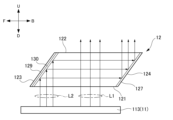
- a low-reflection film 129 may be provided on the first reflection surface 123.
- the low-reflection film 129 is formed so that the light reflectance on the first reflection surface 123 is 50%.
- the reflectance of the external light L10 reflected by the first reflecting surface 123 is reduced, so that the amount of external light L10 that propagates through the prism 12, is emitted from the prism 12, and enters the image generating unit 11 can be reduced.
- the first reflecting surface 123 may be provided with a phase shift prevention film 130 in addition to the low reflection film 129.
- the second light L2 incident from the incident surface 121 is reflected by the first reflecting surface 123
- a phase shift occurs in the second light L2, which may degrade the quality of the second virtual image.
- the second light L2 which is linearly polarized light emitted from the image generating unit 11, becomes elliptically polarized light when reflected by the first reflecting surface 123, and a portion of the second light L2 is not reflected by the reflective polarizing film 127.
- a phase shift prevention film 130 on the first reflecting surface 123 it is possible to prevent phase shift due to total reflection of the second light L2, and suppress degradation of the quality of the second virtual image.
- the first reflecting surface 123 is configured to totally reflect the second light L2, and the second reflecting surface 124 is provided with a reflective polarizing film 127 that reflects light in a predetermined vibration direction.
- the second reflecting surface 124 may be configured to totally reflect the second light L2, and the first reflecting surface 123 may be provided with a reflective polarizing film 127 that reflects light in a predetermined vibration direction.
- the prism 12 is configured to control the first light L1 that becomes the first virtual image and the second light L2 that becomes the second virtual image.
- the prism 12 may be configured to control only the second light L2. Even in this case, it is possible to prevent the external light L10 from propagating through the prism 12 and entering the image generating unit 11, and it is possible to prevent the occurrence of heat damage caused by the external light L10.
- the prism 32 according to the second embodiment is formed in a parallelepiped shape having an entrance surface 121, an exit surface 122, a first reflecting surface 123, a second reflecting surface 124, a first side surface 125, and a second side surface 126, similar to the prism 12 according to the first embodiment.
- the incident surface 121 is disposed opposite the image generating unit 11 (display device 113) and is configured to receive the first light L1 and the second light L2 emitted from the image generating unit 11.
- the image generating unit 11 includes a first emitting unit 113A that emits the first light L1, and a second emitting unit 113B that is provided at a position different from the first emitting unit 113A.
- the first reflecting surface 123 is configured to reflect the second light L2 incident from the incident surface 121.
- the first reflecting surface 123 can be configured to totally reflect the second light L2.
- the first reflecting surface 123 is configured to reflect the second light L2 toward the second reflecting surface 124 so that the second light L2 propagates within the prism 12 approximately parallel to the incident surface 121.
- the second reflecting surface 124 faces the first reflecting surface 123.
- the second reflecting surface 124 is configured to reflect the second light L2 reflected by the first reflecting surface 123 toward the exit surface 122.
- the second reflecting surface 124 can be configured to totally reflect the second light L2.
- the first side 125 and the second side 126 face each other.
- the first side 125 is adjacent to the first reflecting surface 123 and the second reflecting surface 124.
- the second side 126 is adjacent to the first reflecting surface 123 and the second reflecting surface 124.
- the exit surface 122 faces the entrance surface 121.
- the exit surface 122 is configured to emit the first light L1 and the second light L2 that have propagated within the prism 12.
- the first light L1 emitted from the image generating unit 11 is incident on the incident surface 121 at a substantially right angle, propagates through the prism 12 towards the exit surface 122, and is emitted from the exit surface 122 without being reflected by the first reflecting surface 123 and the second reflecting surface 124.
- the second light L2 emitted from the image generating unit 11 is incident on the incident surface 121 at a substantially right angle or obliquely, is reflected by the first reflecting surface 123 and the second reflecting surface 124, and is emitted from the exit surface 122.
- the prism 32 further includes a light-shielding portion 321.
- the prism 32 includes a plurality of light-shielding portions 321a arranged on the entrance surface 121 and a plurality of light-shielding portions 321b arranged on the exit surface 122.
- the light-shielding portion 321 is formed to extend in the direction in which the incident surface 121 and the exit surface 122 face each other (the up-down direction in the figure). Specifically, the light-shielding portion 321a arranged on the incident surface 121 side extends toward the exit surface 122 side. The light-shielding portion 321b arranged on the exit surface 122 side extends toward the incident surface 121 side. In other words, the light-shielding portion 321 extends in a direction that intersects with the propagation direction of the second light L2.
- the cross-sectional shape of the tip of the light-shielding portion 321 is rectangular.
- the cross-sectional shape of the tip of the light-shielding portion 321 may be round, wedge-shaped, or the like.
- FIG. 11 is a view of the prism 32 seen from below
- FIG. 12 is a view of the prism of FIG. 10 seen from above.
- the light-shielding portion 321 extends in a direction in which the first side 125 and the second side 126 face each other (the left-right direction in the figure). In this example, the light-shielding portion 321 extends from the first side 125 to the second side 126.
- the light-shielding portion 321 is not provided on the incident surface 121 in the incident region R1 where the first light L1 is incident and the incident region R2 where the second light L2 is incident. Also, as illustrated in FIG. 12, the light-shielding portion 321 is not provided on the exit surface 122 in the exit region R11 where the first light L1 is emitted and the exit region R12 where the second light L2 is emitted.
- the light-shielding portion 321 is formed from metal, black resin, or the like.
- the light-shielding portion 321 is formed by fitting a metal plate into the prism 32, pressing black resin into it, or pasting black resin onto it.
- the light-shielding portion 321 may be formed by a cutout.
- the light-shielding portion 321 may be formed by insert molding or the like when molding the prism 32.
- the second light L2 reflected by the first reflecting surface 123 toward the second reflecting surface 124 is designed to basically propagate within the prism 32 approximately parallel to the incident surface 121, as described above.
- the first reflecting surface 123 there are cases where light is emitted from the image generating unit 11 in an unintended direction, or where light is reflected in an unintended direction by the first reflecting surface 123.
- light traveling in such an unintended direction is emitted from the prism 32, it may become stray light.
- the prism 32 according to the second embodiment the light L21a, L21b reflected in an unintended direction by the first reflecting surface 123 is blocked by the light blocking portion 321 before it reaches the incident surface 121 or the exit surface 122. Therefore, the light L21a, L21b, which may become stray light, is prevented from reaching the second reflecting surface 124 by the light blocking portion 321, and can be prevented from becoming stray light.
- the light shielding portion 321 is disposed on both the incident surface 121 and the exit surface 122 of the prism 12.
- the light L21a located near the incident surface 121 is easily blocked by the light shielding portion 321a provided on the incident surface 121.
- the light L21b located near the exit surface 122 is easily blocked by the light shielding portion 321b provided on the exit surface 122. This can further suppress the occurrence of stray light.
- the light shielding portion 321 may be disposed on either the entrance surface 121 or the exit surface 122. This configuration also makes it possible to suppress the occurrence of stray light.
- the light shielding portion 321 is formed so as to extend in the direction in which the incident surface 121 and the exit surface 122 face each other. Therefore, the light shielding portion 321 can easily block light that is reflected by the first reflecting surface 123 and travels toward the incident surface 121 or the exit surface 122.
- the light-shielding portion 321 is not provided on the entrance surface 121 and the exit surface 122 in the entrance region R1 where the first light L1 enters and the exit region R11 where it exits, and in the entrance region R2 where the second light L2 enters and the exit region R12 where it exits. Therefore, it is possible to prevent the first light L1 or the second light L2 entering the prism 32 or exiting from the prism 32 from being blocked.
- the light shielding portions 321 are arranged in multiple locations on each of the incident surface 121 and the exit surface 122. By providing the light shielding portions 321 in multiple locations in this manner, it is possible to block light that may become stray light reflected from the first reflecting surface 123 at various angles, and the occurrence of stray light can be further suppressed. Note that, in this example, four light shielding portions 321 are provided on each of the incident surface 121 and the exit surface 122, but the number of light shielding portions 321 is not limited to this example.
- the light-shielding portion 321 extends inside the prism 12, but it may also be configured to extend further toward the outside of the prism 12.
- Figures 13 and 14 show different configurations of the prism.
- the light-shielding portion 321 extends from the entrance surface 121 and the exit surface 122 toward the outside of the prism 32, and the ends of two adjacent light-shielding portions 321 may be connected by a connecting portion 322.
- the light-shielding portion 321 extends from the first side surface 125 and the second side surface 126 toward the outside of the prism 32, and the connecting portions 322 arranged to surround the exit region R11 from which the first light of the exit surface 122 is emitted may be connected to each other.
- the light-shielding portion 321 also has a similar structure on the entrance surface 121 side.
- the light shielding portion 321 arranged on the entrance surface 121 of the prism 32 can be used as a fixing member for fixing the prism 32 to the image generating unit 11, so there is no need for a separate dedicated fixing member for fixing the prism 32.
- the configuration of the portion of the light shielding portion 321 exposed from the prism 32 is not limited to the configuration of this example, as long as it has a shape that allows the image generating unit 11 to be fixed.
- FIG. 15 shows another configuration of the prism.
- the light-shielding portion 321 may be configured to extend from the exit surface 122 toward the outside of the prism 32 so as to separate the optical path of the first light L1 emitted from the exit surface 122 from the optical path of the second light L2.
- light L31 that reaches the entrance surface 121 or the exit surface 122 without being blocked by the light blocking portion 321 can be prevented from becoming stray light due to being reflected by the entrance surface 121 or the exit surface 122, and then being reflected by the second reflecting surface 124 and crosstalking with the first light L1.
- the light blocking portion 321 is disposed on the incident surface 121 and the exit surface 122.
- the light blocking portion 321 may be disposed on at least one of the first side surface 125 and the second side surface 126 in addition to the incident surface 121 and the exit surface 122.
- FIG. 16 shows another configuration of the prism 32.
- FIG. 16 is a view of the prism 32 as viewed from above.
- the light blocking portion 321 may be disposed on the first side surface 125 and the second side surface 126.
- the light blocking portion 321 extends, for example, in a direction in which the incident surface 121 and the exit surface 122 face each other (the up-down direction in the figure).
- This configuration prevents the second light L2 reflected by the first reflecting surface 123 from reaching the first side surface 125 or the second side surface 126 and being reflected there, thereby preventing it from becoming stray light.
- the light shielding portion 321 is disposed on both the first side surface 125 and the second side surface 126, but the light shielding portion 321 may be disposed on either the first side surface 125 or the second side surface 126.
- the light-shielding portion 321 according to the second embodiment may be provided in the prism 12 according to the first embodiment.
- FIG. 17 illustrates another configuration of the prism 12.
- the prism 12 may be provided with a light-shielding portion 321 extending into the interior of the prism 12 on at least one of the entrance surface 121 and the exit surface 122.
- Fig. 18 is a perspective view illustrating the configuration of the prism 22.
- Fig. 19 is a cross-sectional view illustrating the configuration of the prism 22.
- the prism 22 is formed in a parallelepiped shape having an entrance surface 221, an exit surface 222, a first reflecting surface 223, a second reflecting surface 224, a first side surface 225, and a second side surface 226.
- the incident surface 221 is disposed opposite the image generating unit 11 (see FIG. 1) and is configured so that the first light L1 and the second light L2 emitted from the image generating unit 11 are incident thereon.
- the first reflecting surface 223 is configured to reflect the second light L2 incident from the incident surface 221.
- the first reflecting surface 223 is configured to totally reflect the second light L2.
- the first reflecting surface 223 is configured to reflect the second light L2 toward the second reflecting surface 224 so that the second light L2 propagates within the prism 22 approximately parallel to the incident surface 221.
- the second reflecting surface 224 faces the first reflecting surface 223.
- the second reflecting surface 224 is configured to reflect the second light L2 reflected by the first reflecting surface 223 toward the emission surface 222.
- the second reflecting surface 224 is configured to totally reflect the second light L2.
- the first side 225 and the second side 226 face each other.
- the first side 225 is adjacent to the first reflecting surface 223 and the second reflecting surface 224.
- the second side 226 is adjacent to the first reflecting surface 223 and the second reflecting surface 224.
- the exit surface 222 faces the entrance surface 221.
- the exit surface 222 is configured to emit the first light L1 and the second light L2 that have propagated within the prism 22.
- Prism 22 is divided in the direction in which first reflecting surface 223 and second reflecting surface 224 face each other (front-to-back direction in FIG. 18). Specifically, prism 22 has first prism portion 22A and second prism portion 22B. First prism portion 22A is an example of a first optical element. Second prism portion 22B is an example of a second optical element.
- the first prism portion 22A and the second prism portion 22B are formed from a light-transmitting material.
- light-transmitting materials include glass materials and transparent resin materials such as acrylic and polycarbonate.
- the first prism portion 22A and the second prism portion 22B are formed separately. Each of the first prism portion 22A and the second prism portion 22B is formed, for example, by molding the light-transmitting material with a mold.
- the first prism portion 22A and the second prism portion 22B are bonded to each other.
- the prism 22 has an adhesive portion 227.
- the first prism portion 22A and the second prism portion 22B are bonded to each other by the adhesive portion 227.
- an adhesive having translucency such as an acrylic, silicone, or epoxy adhesive, or an adhesive sheet having adhesive properties on both sides is used as the adhesive portion 227.
- the adhesive surface 22A1 that is adhered to the second prism portion 22B of the first prism portion 22A extends approximately perpendicular to the incident surface 221.
- the adhesive surface 22B1 that is adhered to the first prism portion 22A of the second prism portion 22B extends approximately perpendicular to the incident surface 221.
- the adhesive surfaces 22A1 and 22B1 are adhered to each other by an adhesive portion 227, and the adhesive portion 227 extends approximately perpendicular to the incident surface 221.
- the expression "extending substantially perpendicularly” used in this specification does not only mean extending perpendicularly, but also includes extending in a direction within a range of ⁇ 10 degrees or less from the perpendicular direction.
- the expression “extending substantially parallel” does not only mean extending parallel, but also includes extending in a direction within a range of ⁇ 10 degrees or less from the parallel direction.
- the first light L1 emitted from the image generating unit 11 is incident at a substantially right angle to the incident surface 221, and propagates through the prism 22 toward the exit surface 222.
- the first light L1 propagates along a direction parallel to the adhesive surfaces 22A1 and 22B1.
- the first light L1 is then emitted from the exit surface 222 without being reflected by the first reflecting surface 223 and the second reflecting surface 224.
- the first optical path of the first light L1 extends substantially parallel to the adhesive surfaces 22A1 and 22B1.
- the second light L2 emitted from the image generating unit 11 is emitted from a position different from the position where the first light L1 is emitted (see FIG. 1).
- the second light L2 is incident on the incident surface 221 at a substantially right angle or obliquely, and is incident on the first reflecting surface 223 at an angle at which it is totally reflected. As a result, it is reflected by the first reflecting surface 223 toward the second reflecting surface 224.
- the second light L2 that reaches the second reflecting surface 224 is reflected by the second reflecting surface 224 toward the exit surface 222, and exits from the exit surface 222.
- the second light L2 propagates between the first reflecting surface 223 and the second reflecting surface 224 along a direction perpendicular to the adhesive surfaces 22A1 and 22B1. That is, the second optical path of the second light L2 extends substantially perpendicular to the adhesive surfaces 22A1 and 22B1.
- the prism 22 is formed in a flattened rectangular shape (parallelogram in this example) in a cross-sectional view, and is configured so that the length in the direction in which the first reflecting surface 223 and the second reflecting surface 224, through which the second light L2 propagates, is large.
- the prism 22 has a length of about 20 mm in the direction in which the entrance surface 221 and the exit surface 222 face each other, a length of about 220 mm in the direction in which the first side surface 225 and the second side surface 226 face each other, and a length of about 45 mm in the direction in which the first reflecting surface 223 and the second reflecting surface 224 face each other.
- the first prism portion 22A and the second prism portion 22B are formed separately, and the first prism portion 22A and the second prism portion 22B are bonded together to form the prism 22. This suppresses the anisotropy of the dimensions of the prism 22, making it easier to mold the prism 22 with precision.
- the adhesive portion 227 may affect the propagation of the light beam.
- the adhesive portion 227 in a cross section perpendicular to the incident surface 221, the adhesive portion 227 extends approximately perpendicular to the incident surface 221. Therefore, the effect of the adhesive portion 227 on the propagation of the second light L2, which propagates further within the prism 22, can be suppressed.
- the first prism portion 22A, the second prism portion 22B, and the adhesive portion 227 may be formed from the same type of resin.
- the term "same type of resin” is not limited to cases where the resin components are completely the same, but also includes resins with the same main components, such as acrylic resins. In this way, when the first prism portion 22A and the second prism portion 22B, and the adhesive portion 227 are formed from the same type of resin, the difference in refractive index between the first prism portion 22A and the second prism portion 22B, and the adhesive portion 227 becomes small, so that the effect on the propagation of the first light L1 and the second light L2 can be suppressed.
- the surface roughness of the adhesive surface 22A1 of the first prism portion 22A and the adhesive surface 22B1 of the second prism portion 22B may be formed to be rougher than the surface roughness of the surfaces (such as the entrance surface 221 and the exit surface 222) that form the outer surface of the prism 22. This improves the adhesion between the adhesive surface 22A1 and the adhesive surface 22B1 and the adhesive portion 227.
- the prism 22 is divided into two prism parts, but it may be divided into three or more prism parts.
- the adhesive portion 227 extends substantially perpendicular to the incident surface 221 in a cross section perpendicular to the incident surface 221.
- the adhesive portion 227 may extend obliquely relative to the incident surface 221.
- FIG. 20 shows the configuration of a prism 220 according to a modified example.
- the adhesive surface 22A1 of the first prism portion 22A and the adhesive surface 22B1 of the second prism portion 22B extend obliquely with respect to the incident surface 221.
- the adhesive portion 227 that bonds the adhesive surface 22A1 and the adhesive surface 22B1 extends obliquely with respect to the incident surface 221.
- the first reflecting surface 223 and the second reflecting surface 224 are configured to totally reflect the first light L1 and the second light L2, respectively.
- the reflection at the first reflecting surface 223 and the second reflecting surface 224 does not have to be total reflection.
- first prism portion 22A and the second prism portion 22B are bonded by the adhesive portion 227.
- first prism portion 22A and the second prism portion 22B may be bonded by solvent bonding or polymerization bonding.
- Fig. 21 is a perspective view illustrating an example of the configuration of the prism 42.
- Fig. 22 is a cross-sectional view illustrating an example of the configuration of the prism 42 and the display device 113 of the image generating unit 11.
- the prism 42 is formed in a generally parallelepiped shape having an entrance surface 421, an exit surface 422, a first reflecting surface 423, a second reflecting surface 424, a first side surface 425, and a second side surface 426.
- the incident surface 421 is disposed opposite the image generating unit 11 and is configured so that the first light L1 and the second light L2 emitted from the image generating unit 11 are incident thereon.
- the first reflecting surface 423 is configured to reflect the second light L2 incident from the incident surface 421.
- the first reflecting surface 423 can be configured to totally reflect the second light L2.
- the first reflecting surface 423 is configured to reflect the second light L2 toward the second reflecting surface 424 so that the second light L2 propagates within the prism 42 approximately parallel to the incident surface 421.
- the second reflecting surface 424 faces the first reflecting surface 423.
- the second reflecting surface 424 is configured to reflect the second light L2 reflected by the first reflecting surface 423 toward the exit surface 422.
- the second reflecting surface 424 can be configured to totally reflect the second light L2.
- the first side 425 and the second side 426 face each other.
- the first side 425 is adjacent to the first reflecting surface 423 and the second reflecting surface 424.
- the second side 426 is adjacent to the first reflecting surface 423 and the second reflecting surface 424.
- the exit surface 422 faces the entrance surface 421.
- the exit surface 422 is configured to emit the first light L1 and the second light L2 that have propagated through the prism 42.
- the display device 113 of the image generating unit 11 is disposed so as to face the prism 42.
- the display device 113 includes a first emission section 113A that emits the first light L1, and a second emission section 113B that is provided at a position different from the first emission section 113A.
- the first light L1 emitted from the first emission section 113A of the image generating unit 11 enters the entrance surface 421 at a substantially right angle or at an angle, propagates through the prism 42 toward the exit surface 422, and is emitted from the exit surface 422 without being reflected by the first reflecting surface 423 and the second reflecting surface 424.
- the second light L2 emitted from the second emission section 113B of the image generating unit 11 is incident on the incident surface 421 at a substantially right angle or at an angle, and is reflected by the first reflecting surface 423 toward the second reflecting surface 424.
- the second light L2 that reaches the second reflecting surface 424 is reflected by the second reflecting surface 424 toward the exit surface 422, and is emitted from the exit surface 422.
- first light L1 and the second light L2 are actually refracted at the incident surface 421 and the exit surface 422, but since the effect of refraction is small, for the sake of convenience in this specification, refraction will be ignored. Also, in some figures, the refraction is not shown for the sake of simplicity.
- ⁇ p1 is the emission angle of the second light L2 relative to the image generating surface 113B1 of the second emission section 113B of the display device 113 in a cross section perpendicular to the incident surface 421 of the prism 42.
- ⁇ p2 is the emission angle of the first light L1 relative to the image generating surface 113A1 of the first emission section 113A of the display device 113 in a cross section perpendicular to the incident surface 421 of the prism 42.
- ⁇ p1 and ⁇ p2 represent the angles between the image generating surface 1131 of the display device 113 and the first light L1 and second light L2, and in FIG. 22, the counterclockwise direction from the image generating surface 1131 is considered to be a positive angle.
- ⁇ p1 and ⁇ p2 are determined so that the first light L1 and the second light L2 are emitted parallel to each other from the image generating unit 11. Specifically, when the image generating surface 1131 of the image generating unit 11 is flat, ⁇ p1 and ⁇ p2 are set to the same angle. In this example, ⁇ p1 and ⁇ p2 are 90°. ⁇ p1 and ⁇ p2 can be set to desired values, for example, by adjusting the angle of the light incident on the display device 113 by the optical element 142 in the image generating unit 11.
- ⁇ 1 is the angle between the incident surface 421 and the first reflecting surface 423 in a cross section perpendicular to the incident surface 421.
- ⁇ 2 is the angle between the second reflecting surface 424 and the exit surface 422 in a cross section perpendicular to the incident surface 421.
- the prism 42 is configured so that ⁇ 1 is smaller than ⁇ 2. For example, ⁇ 1 is 44° and ⁇ 2 is 45°.
- FIG. 23 illustrates a prism 42A in which ⁇ 1 and ⁇ 2 are the same, unlike the prism 42 of this embodiment.
- FIG. 24 is a diagram for explaining the optical path of the first light L1 and the optical path of the second light L2 emitted from the prism 42A and incident on the concave mirror 13.
- the dashed line indicates the optical path of the first light L1
- the solid line indicates the optical path of the second light L2.
- the reflecting surface 131 of the concave mirror 13 is simplified and shown as a flat surface.
- the second light L2 is emitted from the exit surface 422 of the prism 42A in parallel with the first light L1.
- ⁇ 0.
- ⁇ can be expressed using the following formula (1).
- the first light L1 and the second light L2 emitted from the prism 42 toward the concave mirror 13 are incident on the reflecting surface 131 of the concave mirror 13 at positions spaced apart from each other.
- ⁇ 1 of the prism 42 is greater than ⁇ 2
- the second light L2 is emitted from the exit surface 422 of the prism 42 in a direction away from the first light L1. That is, ⁇ , which is the angle between the optical path of the first light L1 and the optical path of the second light L2 emitted from the exit surface 422, is ⁇ 0.
- the reflecting surface 131 of the concave mirror 13 must have a size D1 that allows at least the first light L1 and the second light L2 to be incident at positions separated from each other.
- ⁇ 1 is smaller than ⁇ 2. Therefore, as illustrated in FIG. 22, the second light L2 is emitted from the exit surface 422 of the prism 42 in a direction intersecting with the first light L1. That is, ⁇ , which is the angle between the optical path of the first light L1 emitted from the exit surface 422 and the optical path of the second light L2, is ⁇ >0.
- Figure 25 is a diagram for explaining the optical path of the first light L1 and the second light L2 emitted from the prism 42 and incident on the concave mirror 13. As illustrated in Figure 25, when ⁇ >0, the first light L1 and the second light L2 emitted from the prism 42 toward the concave mirror 13 are incident on the reflecting surface 131 of the concave mirror 13 at a position where they at least partially overlap.
- the reflecting surface 131 of the concave mirror 13 only needs to have a size D2 that allows at least the first light L1 and the second light L2 to be incident in a partially overlapping state, so the concave mirror 13 can be prevented from becoming too large.
- ⁇ can be set to satisfy 0 ⁇ 7.
- ⁇ can be set to 5°.
- the first light L1 and the second light L2 will intersect in front of the concave mirror 13, and the first light L1 and the second light L2 traveling in directions away from each other will be incident on the reflecting surface 131 of the concave mirror 13. If the concave mirror 13 is moved closer to the prism 42 in order to prevent the first light L1 and the second light L2 from being incident at positions away from each other on the reflecting surface 131 of the concave mirror 13, the optical path length of the first light L1 and the optical path length of the second light L2 will be shortened.
- the first light L1 and the second light L2 are emitted in parallel from the image generation surface 1131 of the image generation unit 11.
- the first light L1 and the second light L2 may be configured to be emitted in directions away from each other from the image generation surface 1131 of the image generation unit 11.
- FIG. 26 shows a light path diagram in which the first light L1 and the second light L2 are emitted in directions away from each other from the image generating unit 11.
- ⁇ p1 which is the emission angle of the second light L2 relative to the image generating surface 1131
- ⁇ p2 which is the emission angle of the first light L1 relative to the image generating surface 1131
- ⁇ p1 is set to be greater than 90°
- ⁇ p2 is set to be less than 90°
- ⁇ p1 and ⁇ p2 may be set so that ⁇ p1 is less than 90°
- ⁇ p2 is set to be greater than 90°.
- ⁇ p1 and ⁇ p2 may be set so that one is 90° and the other is greater than 90°.
- the first light L1 and the second light L2 are emitted from the image generating unit 11 in directions away from each other, so that the first light L1 and the second light L2 are emitted from the exit surface 422 in directions approaching each other.
- the first light L1 incident from the entrance surface 421 propagates within the prism 42 and is emitted from the exit surface 422 in a direction approaching the second light L2.
- the second light L2 incident from the entrance surface 421 is reflected by the first reflecting surface 423 and the second reflecting surface 424, and is emitted from the exit surface 422 in a direction approaching the first light L1.
- the angle ⁇ between the optical path of the first light L1 emitted from the exit surface 422 and the optical path of the second light L2 is ⁇ >0.
- the first light L1 and the second light L2 emitted from the prism 42 toward the concave mirror 13 are incident on the reflecting surface 131 of the concave mirror 13 at a position where at least a portion of the light overlaps, preventing the concave mirror 13 from becoming large.
- the occurrence of crosstalk and stray light can be suppressed.
- FIG. 27 is a diagram for explaining the optical paths of the first light L1 and the second light L2 propagating through the prism 42.
- the dashed line indicates the optical path of the first light L1
- the solid line indicates the optical path of the second light L2.
- the first light L1 and the second light L2 emitted from the image generating unit 11 each travel with a predetermined area in a direction perpendicular to the direction of travel, but in reality, there may be cases where light is emitted from the image generating unit 11 in an unintended direction, or where light is reflected in an unintended direction by the first reflecting surface 423 or the second reflecting surface 424.
- a portion of the second light L2 emitted from the image generating unit 11, called light L41, may spread toward the first light L1 and enter the prism 42.
- this light L41 may mix with the first light L1, causing crosstalk or becoming stray light.
- the first light L1 and the second light L2 are incident on the prism 42 in directions away from each other. This makes it possible to prevent, for example, the light L41 that spreads toward the first light L1 and enters the prism 42 from becoming a cause of crosstalk or stray light, compared to the case in which the first light L1 and the second light L2 are emitted in parallel from the image generating surface 1131 as illustrated in FIG. 22.
- the prism 42 is arranged so that the incident surface 421 is parallel to the image generating surface 1131 of the image generating unit 11.
- the prism 42 may be arranged so that the incident surface 421 is inclined with respect to the image generating surface 1131 of the image generating unit 11.
- FIG. 28 illustrates a configuration in which the incident surface 421 of the prism 42 is inclined with respect to the image generating surface 1131 of the image generating unit 11.
- ⁇ 3 is the angle between the image generating surface 1131 of the image generating unit 11 and the incident surface 421.
- ⁇ 3 is set to satisfy 0 ⁇ 3 ⁇ 10.
- Preferably, ⁇ 3 is set to 5°.
- the orientation of the first reflecting surface 423 approaches a direction perpendicular to the image generating surface 1131 of the image generating unit 11, and the optical design will be such that the second reflecting surface 424 is positioned higher than the first reflecting surface 423, making the optical design more difficult. Therefore, by making ⁇ 3 ⁇ 10, ⁇ can be made larger while preventing the optical design from becoming complicated.
- the first light L1 and the second light L2 may be configured to be emitted in directions away from each other from the image generating unit 11.
- FIG. 29 shows an optical path diagram in which the first light L1 and the second light L2 are emitted in directions away from each other from the image generating surface 1131 of the image generating unit 11 in the arrangement of the prism 42 and the image generating unit 11 in FIG. 28.
- the prism 42 may be configured so that the second optical path of the second light L2 extends approximately parallel to the entrance surface 421 and the exit surface 422 of the prism 42.
- FIG. 30 illustrates a prism 42 in which the second optical path of the second light L2 extends approximately parallel to the entrance surface 421 and the exit surface 422 when ⁇ 3>0 and ⁇ p1> ⁇ p2.
- the second optical path of the second light L2 reflected from the first reflecting surface 423 toward the second reflecting surface 424 extends substantially parallel to the entrance surface 421 and the exit surface 422 of the prism 42.
- the expression "extending substantially parallel” does not only mean extending parallel, but also includes extending in a direction within a range of ( ⁇ ) 10 degrees or less from the parallel direction.
- the second optical path of the second light L2 can be made approximately parallel to the entrance surface 421 and exit surface 422 of the prism 42.
- the second light L2 can be propagated substantially parallel to the entrance surface 421 and the exit surface 422 of the prism 42, as compared to the optical path of the second light L2 shown in FIG. 29, for example. This allows the prism 42 to be made thinner.
- the angle ⁇ 1 between the incident surface 421 and the first reflecting surface 423, the emission angle ⁇ p1 of the second light relative to the image generating surface 1131, and the angle ⁇ 3 between the image generating surface 1131 and the incident surface 421 may be set to satisfy the following formula (2).
- the angle of incidence ⁇ 6 (see FIG. 28) of the second light L2 with respect to the first reflecting surface 423 is set to be greater than 40° and less than 50°.
- the critical angle of total reflection of the light-transmitting material that constitutes prism 42 is around 43 degrees.
- prism 42 is made of methacrylic resin, commonly known as acrylic resin (Poly Methyl Methacrylate/PMMA)
- acrylic resin Poly Methyl Methacrylate/PMMA
- the critical angle of total reflection of PMMA is 43 degrees. Therefore, by setting the incident angle ⁇ 6 to be greater than 40°, first reflecting surface 423 can totally reflect second light L2 or reflect a large amount of second light L2. On the other hand, if the incident angle ⁇ 6 is 50 degrees or greater, optical design becomes difficult.
- the HUD 110 further includes a light blocking unit 16 in addition to the image generating unit 11, the prism 52, the concave mirror 13, the concave mirror 14, and the control unit 15.
- FIG. 32 is a cross-sectional view illustrating the configuration of the prism 52 and the display device 113 of the image generating unit 11.
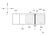
- FIG. 33 is a plan view of the prism 52 seen from above.
- the prism 52 is formed in a generally parallelepiped shape having an entrance surface 421, an exit surface 422, a first reflecting surface 423, a second reflecting surface 424, a first side surface 425, and a second side surface 426.
- the incident surface 421 is disposed opposite the image generating unit 11 and is configured so that the first light L1 and the second light L2 emitted from the image generating unit 11 are incident thereon.
- the first reflecting surface 423 is configured to reflect the second light L2 incident from the incident surface 421.
- the first reflecting surface 423 can be configured to totally reflect the second light L2.
- the first reflecting surface 423 is configured to reflect the second light L2 toward the second reflecting surface 424 so that the second light L2 propagates within the prism 42 approximately parallel to the incident surface 421.
- the second reflecting surface 424 faces the first reflecting surface 423.
- the second reflecting surface 424 is configured to reflect the second light L2 reflected by the first reflecting surface 423 toward the exit surface 422.
- the second reflecting surface 424 can be configured to totally reflect the second light L2.
- the first side 425 and the second side 426 face each other.
- the first side 425 is adjacent to the first reflecting surface 423 and the second reflecting surface 424.
- the second side 426 is adjacent to the first reflecting surface 423 and the second reflecting surface 424.
- the exit surface 422 faces the entrance surface 421.
- the exit surface 422 is configured to emit the first light L1 and the second light L2 that have propagated through the prism 42.
- the display device 113 of the image generating unit 11 is disposed so as to face the prism 52.
- the display device 113 includes a first emission section 113A that emits the first light L1, and a second emission section 113B that is provided at a position different from the first emission section 113A.
- the first light L1 emitted from the first emission section 113A of the image generating unit 11 enters the entrance surface 421 at a substantially right angle or at an angle, propagates through the prism 42 toward the exit surface 422, and is emitted from the exit surface 422 without being reflected by the first reflecting surface 423 and the second reflecting surface 424.
- the second light L2 emitted from the second emission section 113B of the image generating unit 11 is incident on the incident surface 421 at a substantially right angle or at an angle, and is reflected by the first reflecting surface 423 toward the second reflecting surface 424.
- the second light L2 that reaches the second reflecting surface 424 is reflected by the second reflecting surface 424 toward the exit surface 422, and is emitted from the exit surface 422.
- the light blocking portion 16 is arranged so as to separate the optical path of the first light L1 emitted from the exit surface 422 from the optical path of the second light L2. In this example, the light blocking portion 16 is in contact with the exit surface 422 of the prism 52.
- the light shielding portion 16 is a plate-like member. As illustrated in FIG. 32, the light shielding portion 16 extends in a direction that is approximately vertical to the light output surface 422 (the up-down direction in FIG. 32). Note that in this specification, the expression "extending in an approximately vertical direction” does not only mean extending in the vertical direction, but also includes extending in a direction within a range of ⁇ 10 degrees or less from the vertical direction.
- the tip portion of the light-shielding portion 16 that faces away from the light-emitting surface 422 is formed to have a square cross section.
- the tip portion of the light-shielding portion 16 may have a round cross section, or may be formed so that the cross section becomes thinner toward the tip.
- the light-shielding portion 16 extends in a direction in which the first side 425 and the second side 426 face each other (the left-right direction in FIG. 33). In this example, the light-shielding portion 16 extends from the first side 425 to the second side 426.
- the light shielding portion 16 is provided on the emission surface 422 between the emission region R21 from which the first light L1 is emitted and the emission region R22 from which the second light L2 is emitted.
- the light shielding portion 16 has a first surface 161 facing the first light L1 and a second surface 162 facing the second light L2 each formed in a flat shape.
- the light shielding portion 16 may be formed in other shapes, such as curved, to match the emission region R21 from which the first light L1 is emitted and the emission region R22 from which the second light L2 is emitted.
- the light-shielding portion 16 is formed so that the thickness T in the direction in which the first surface 161 and the second surface 162 face each other is thin.
- the thickness T is 0.1 mm or less.
- the light shielding portion 16 is, for example, a metal plate such as stainless steel. Alternatively, the light shielding portion 16 may be formed from a black resin or the like. The first surface 161 and the second surface 162 of the light shielding portion 16 may be subjected to an anti-reflection treatment.
- the second light L2 reflected by the first reflecting surface 423 towards the second reflecting surface 424 is basically designed to propagate within the prism 52 approximately parallel to the incident surface 421.
- the image generating unit 11 there are cases where light is emitted from the image generating unit 11 in an unintended direction, or where light L51 is reflected in an unintended direction by the first reflecting surface 423 or the second reflecting surface 424.
- light L51 traveling in an unintended direction like this is emitted from the prism 52, it can result in crosstalk or stray light.
- a light blocking portion 16 is provided between the optical path of the first light L1 emitted from the prism 52 and the optical path of the second light L2, so that it is possible to block the light L51 that is reflected in an unintended direction and may cause crosstalk or stray light.
- the light-shielding portion 16 can be prevented from blocking the first light L1 and the second light L2 emitted in the intended direction from the light-emitting surface 422.
- the light-shielding portion 16 is a metal plate, the light-shielding effect is improved.
- the light blocking portion 16 is in contact with the exit surface 422 of the prism 52.
- the light blocking portion 16 may be disposed away from the exit surface 422 of the prism 52 as long as it is in the vicinity of the exit surface 422 of the prism 52.
- FIG. 34 illustrates a configuration of the HUD 110 in which the light shielding portion 16 is separated from the prism 52.
- the light shielding portion 16 is attached to the housing of the HUD 110 by a support member (not shown). Even with this configuration, it is possible to block light L51 that is reflected in an unintended direction from the exit surface 422 and may cause crosstalk or stray light.
- a portion of the light blocking portion 16 may be embedded in the exit surface 422 of the prism 52.
- FIG. 35 illustrates a HUD 110 in which a portion of the light blocking portion 16 is embedded in the prism 52.
- a portion of the light blocking portion 16 on the prism 52 side is embedded between the emission region R11 of the first light L1 and the emission region R12 of the second light L2 on the emission surface 422 of the prism 52.
- the light-shielding portion 16 is embedded in the prism 52 by fitting a metal plate into the prism 52, pressing in black resin, or the like.
- the light-shielding portion 16 may be formed by insert molding or the like when molding the prism 52.
- the light blocking portion 16 according to the fifth embodiment may be combined with the prism 42 according to the fourth embodiment.
- FIG. 36 illustrates the light blocking portion 16 provided on the prism 42.
- the light blocking portion 16 is disposed near the exit surface 422 of the prism 42 so as to separate the optical path of the first light L1 and the optical path of the second light L2 emitted from the exit surface 422.
- the tip portion of the light blocking portion 16 in the direction away from the exit surface 422 of the prism 52 is formed so as to become thinner as it approaches the tip.
- the light shielding portion 16 can block light L51 that is reflected in an unintended direction from the exit surface 422 and may cause crosstalk or stray light.
- the tip portion of the light-shielding portion 16 is formed so that it becomes thinner toward the tip, so that even if the first light L1 and the second light L2 are emitted from the emission surface 422 so that they intersect, it is possible to prevent the first light L1 and the second light L2 from being blocked.
- the light-shielding portion 16 is in contact with the exit surface 422, but it may be disposed away from the exit surface 422, or a portion of it may be embedded in the prism 42.
- the first reflecting surface 423 is configured to be totally reflective.
- the second reflecting surface 424 is configured to be totally reflective.
- the first reflecting surface 423 and the second reflecting surface 424 do not have to be totally reflective. In this case, the reflection efficiency may be improved by forming a reflective film or the like on the first reflecting surface 423 and the second reflecting surface 424.
- the HUD 10 including the prism 42 according to the fourth embodiment and the HUD 110 including the prism 52 according to the fifth embodiment are configured to form the first virtual image and the second virtual image at different distances from the occupant's viewpoint E, but the first virtual image and the second virtual image may be configured to form the same distance from the occupant's viewpoint E.
- the HUD 10 may include an optical element between the prism 42 and the windshield 21, and the optical element may adjust the optical path length of the first light L1, which has a shorter optical path length than the second light L2 emitted from the prism 42, to be longer.
- the HUD 110 may include an optical element between the prism 52 and the windshield 21, and the optical element may adjust the optical path length of the first light L1, which has a shorter optical path length than the second light L2 emitted from the prism 52, to be longer.
- prisms 42 and 52 are given as examples of optical elements, but the present invention is not limited to this.
- the first and second reflecting surfaces of the optical element may each be made of a flat reflecting material.
- the prism in each embodiment is arranged with the emission surface facing upward toward the vehicle 20, but is not limited to this.
- the concave mirror 14 reflects the light emitted from the image generating unit 11 toward the windshield 21.
- the concave mirror 14 may also reflect the light toward a combiner provided on the inside of the windshield 21, for example.
- HUD 10 and HUD 110 have concave mirror 13 and concave mirror 14 as optical systems arranged on the optical path between image generating unit 11 and windshield 21, but the optical elements that make up the optical systems are not limited to this example.
- two plane mirrors may be arranged instead of concave mirror 13 and concave mirror 14, or a concave mirror and a plane mirror may be arranged.
Landscapes
- Engineering & Computer Science (AREA)
- Physics & Mathematics (AREA)
- Mechanical Engineering (AREA)
- General Physics & Mathematics (AREA)
- Optics & Photonics (AREA)
- Chemical & Material Sciences (AREA)
- Combustion & Propulsion (AREA)
- Transportation (AREA)
- Multimedia (AREA)
- Signal Processing (AREA)
Priority Applications (1)
| Application Number | Priority Date | Filing Date | Title |
|---|---|---|---|
| JP2025510136A JPWO2024203056A1 (https=) | 2023-03-31 | 2024-03-06 |
Applications Claiming Priority (6)
| Application Number | Priority Date | Filing Date | Title |
|---|---|---|---|
| JP2023058734 | 2023-03-31 | ||
| JP2023058735 | 2023-03-31 | ||
| JP2023-058736 | 2023-03-31 | ||
| JP2023-058734 | 2023-03-31 | ||
| JP2023058736 | 2023-03-31 | ||
| JP2023-058735 | 2023-03-31 |
Publications (1)
| Publication Number | Publication Date |
|---|---|
| WO2024203056A1 true WO2024203056A1 (ja) | 2024-10-03 |
Family
ID=92905537
Family Applications (1)
| Application Number | Title | Priority Date | Filing Date |
|---|---|---|---|
| PCT/JP2024/008451 Ceased WO2024203056A1 (ja) | 2023-03-31 | 2024-03-06 | 光学素子および画像投影装置 |
Country Status (2)
| Country | Link |
|---|---|
| JP (1) | JPWO2024203056A1 (https=) |
| WO (1) | WO2024203056A1 (https=) |
Citations (7)
| Publication number | Priority date | Publication date | Assignee | Title |
|---|---|---|---|---|
| JPS6190584A (ja) * | 1984-10-09 | 1986-05-08 | Sony Corp | 投射型デイスプレイ装置 |
| JPH11142783A (ja) * | 1997-11-12 | 1999-05-28 | Olympus Optical Co Ltd | 画像表示装置 |
| JP2001272513A (ja) * | 2000-03-24 | 2001-10-05 | Seiko Epson Corp | 光学部品およびこれを用いたプロジェクタ |
| JP2015172624A (ja) * | 2014-03-11 | 2015-10-01 | オリンパス株式会社 | 虚像観察光学系および導光プリズム |
| JP2017107046A (ja) * | 2015-12-09 | 2017-06-15 | コピン コーポレーション | 装着型映像表示装置 |
| JP2017111324A (ja) * | 2015-12-17 | 2017-06-22 | コピン コーポレーション | 装着型映像表示装置及び接眼光学系 |
| JP2021120750A (ja) * | 2016-12-15 | 2021-08-19 | デュアリタス リミテッド | 車載用表示装置 |
-
2024
- 2024-03-06 JP JP2025510136A patent/JPWO2024203056A1/ja active Pending
- 2024-03-06 WO PCT/JP2024/008451 patent/WO2024203056A1/ja not_active Ceased
Patent Citations (7)
| Publication number | Priority date | Publication date | Assignee | Title |
|---|---|---|---|---|
| JPS6190584A (ja) * | 1984-10-09 | 1986-05-08 | Sony Corp | 投射型デイスプレイ装置 |
| JPH11142783A (ja) * | 1997-11-12 | 1999-05-28 | Olympus Optical Co Ltd | 画像表示装置 |
| JP2001272513A (ja) * | 2000-03-24 | 2001-10-05 | Seiko Epson Corp | 光学部品およびこれを用いたプロジェクタ |
| JP2015172624A (ja) * | 2014-03-11 | 2015-10-01 | オリンパス株式会社 | 虚像観察光学系および導光プリズム |
| JP2017107046A (ja) * | 2015-12-09 | 2017-06-15 | コピン コーポレーション | 装着型映像表示装置 |
| JP2017111324A (ja) * | 2015-12-17 | 2017-06-22 | コピン コーポレーション | 装着型映像表示装置及び接眼光学系 |
| JP2021120750A (ja) * | 2016-12-15 | 2021-08-19 | デュアリタス リミテッド | 車載用表示装置 |
Also Published As
| Publication number | Publication date |
|---|---|
| JPWO2024203056A1 (https=) | 2024-10-03 |
Similar Documents
| Publication | Publication Date | Title |
|---|---|---|
| US11360305B2 (en) | Optical system and wearable display apparatus having the same | |
| US11143872B2 (en) | Waveguide and video image display device | |
| CN115136055B (zh) | 用于减轻重影的光学装置 | |
| US20180231787A1 (en) | Virtual image display device | |
| US10095028B2 (en) | Display light projection optical device | |
| US11698532B2 (en) | Image display device | |
| US10444513B2 (en) | Display apparatus | |
| CN108535870A (zh) | 显示图像投影系统 | |
| KR102664690B1 (ko) | 비대칭 프리즘을 구비한 차량용 헤드업 디스플레이 장치 | |
| JP6917571B2 (ja) | 表示装置 | |
| JP6657943B2 (ja) | ライトガイド及び虚像表示装置 | |
| CN113960801B (zh) | 图像生成单元及其抬头显示器 | |
| JP7478959B2 (ja) | 表示装置、ヘッドアップディスプレイ、移動体、および導光パネル | |
| CN112748572B (zh) | 虚像显示装置及导光部件 | |
| WO2024203056A1 (ja) | 光学素子および画像投影装置 | |
| JP7253717B2 (ja) | 投影装置及びヘッドアップディスプレイ | |
| JP7752614B2 (ja) | 表示装置、ヘッドアップディスプレイ、および移動体 | |
| CN119644599B (zh) | 一种光学膜片和抬头显示装置 | |
| JP7630065B2 (ja) | 表示装置、ヘッドアップディスプレイ、および移動体 | |
| CN220961914U (zh) | 光波导及抬头显示系统 | |
| US20260099046A1 (en) | Display device | |
| US10401554B2 (en) | Light-guiding device and display device | |
| WO2025089198A1 (ja) | 画像生成装置 | |
| KR102097666B1 (ko) | 전방 표시 장치 | |
| CN121348488A (zh) | 用于背光照明单元的光导、背光照明单元及显示装置 |
Legal Events
| Date | Code | Title | Description |
|---|---|---|---|
| 121 | Ep: the epo has been informed by wipo that ep was designated in this application |
Ref document number: 24779191 Country of ref document: EP Kind code of ref document: A1 |
|
| ENP | Entry into the national phase |
Ref document number: 2025510136 Country of ref document: JP Kind code of ref document: A |
|
| WWE | Wipo information: entry into national phase |
Ref document number: 2025510136 Country of ref document: JP |
|
| NENP | Non-entry into the national phase |
Ref country code: DE |
|
| 122 | Ep: pct application non-entry in european phase |
Ref document number: 24779191 Country of ref document: EP Kind code of ref document: A1 |