WO2024202720A1 - テープリールおよびテープカートリッジ - Google Patents
テープリールおよびテープカートリッジ Download PDFInfo
- Publication number
- WO2024202720A1 WO2024202720A1 PCT/JP2024/006196 JP2024006196W WO2024202720A1 WO 2024202720 A1 WO2024202720 A1 WO 2024202720A1 JP 2024006196 W JP2024006196 W JP 2024006196W WO 2024202720 A1 WO2024202720 A1 WO 2024202720A1
- Authority
- WO
- WIPO (PCT)
- Prior art keywords
- reel
- reel hub
- tape
- flange
- outer circumferential
- Prior art date
- Legal status (The legal status is an assumption and is not a legal conclusion. Google has not performed a legal analysis and makes no representation as to the accuracy of the status listed.)
- Ceased
Links
Images






Classifications
-
- G—PHYSICS
- G11—INFORMATION STORAGE
- G11B—INFORMATION STORAGE BASED ON RELATIVE MOVEMENT BETWEEN RECORD CARRIER AND TRANSDUCER
- G11B15/00—Driving, starting or stopping record carriers of filamentary or web form; Driving both such record carriers and heads; Guiding such record carriers or containers therefor; Control thereof; Control of operating function
- G11B15/18—Driving; Starting; Stopping; Arrangements for control or regulation thereof
- G11B15/26—Driving record carriers by members acting directly or indirectly thereon
- G11B15/32—Driving record carriers by members acting directly or indirectly thereon through the reels or cores on to which the record carrier is wound
-
- G—PHYSICS
- G11—INFORMATION STORAGE
- G11B—INFORMATION STORAGE BASED ON RELATIVE MOVEMENT BETWEEN RECORD CARRIER AND TRANSDUCER
- G11B23/00—Record carriers not specific to the method of recording or reproducing; Accessories, e.g. containers, specially adapted for co-operation with the recording or reproducing apparatus ; Intermediate mediums; Apparatus or processes specially adapted for their manufacture
- G11B23/02—Containers; Storing means both adapted to cooperate with the recording or reproducing means
- G11B23/037—Single reels or spools
-
- G—PHYSICS
- G11—INFORMATION STORAGE
- G11B—INFORMATION STORAGE BASED ON RELATIVE MOVEMENT BETWEEN RECORD CARRIER AND TRANSDUCER
- G11B23/00—Record carriers not specific to the method of recording or reproducing; Accessories, e.g. containers, specially adapted for co-operation with the recording or reproducing apparatus ; Intermediate mediums; Apparatus or processes specially adapted for their manufacture
- G11B23/02—Containers; Storing means both adapted to cooperate with the recording or reproducing means
- G11B23/04—Magazines; Cassettes for webs or filaments
- G11B23/08—Magazines; Cassettes for webs or filaments for housing webs or filaments having two distinct ends
- G11B23/107—Magazines; Cassettes for webs or filaments for housing webs or filaments having two distinct ends using one reel or core, one end of the record carrier coming out of the magazine or cassette
-
- G—PHYSICS
- G11—INFORMATION STORAGE
- G11B—INFORMATION STORAGE BASED ON RELATIVE MOVEMENT BETWEEN RECORD CARRIER AND TRANSDUCER
- G11B5/00—Recording by magnetisation or demagnetisation of a record carrier; Reproducing by magnetic means; Record carriers therefor
- G11B5/74—Record carriers characterised by the form, e.g. sheet shaped to wrap around a drum
- G11B5/78—Tape carriers
-
- G—PHYSICS
- G11—INFORMATION STORAGE
- G11B—INFORMATION STORAGE BASED ON RELATIVE MOVEMENT BETWEEN RECORD CARRIER AND TRANSDUCER
- G11B5/00—Recording by magnetisation or demagnetisation of a record carrier; Reproducing by magnetic means; Record carriers therefor
- G11B5/84—Processes or apparatus specially adapted for manufacturing record carriers
Definitions
- This technology relates to a tape reel having a cylindrical reel hub and a tape cartridge equipped with the same.
- a type of magnetic tape cartridge used as an external recording medium for computers and the like is known in which a single tape reel with magnetic tape wound on it is rotatably housed within a cartridge case.
- the tape reel has a cylindrical reel hub around which the magnetic tape is wound, and an upper flange and a lower flange disposed on either end of the reel hub.
- a typical tape reel has a lower flange formed integrally with the reel hub, and an upper flange fixed to the upper end of the reel hub by ultrasonic bonding or the like.
- the upper end of the reel hub which is fixed to the upper flange, deforms inward, causing a large difference in outer diameter between both ends of the reel hub.
- the lower edge of the magnetic tape facing the lower flange deforms so that it becomes longer than the upper edge of the magnetic tape facing the upper flange, which can cause the recording and playback characteristics of the magnetic tape to deteriorate.
- a reel hub has been proposed that has an outer peripheral surface that has a first outer peripheral region that expands in diameter from the bottom end of the reel hub toward its top end, and a second outer peripheral region that expands further in diameter from the first outer peripheral region to the top end of the reel hub (see Patent Document 1).
- the reel hub described in Patent Document 1 can prevent deformation of the lower edge of the magnetic tape after storage in a high-temperature, high-humidity environment, but the difference in tension in the tape width direction caused by the outer peripheral surface shape of the reel hub can impair the linear running of the magnetic tape, which can have a negative effect on stable recording and playback characteristics.
- the objective of this technology is to provide a tape reel and a tape cartridge equipped with the same that can achieve stable recording and playback characteristics while suppressing deformation of the magnetic tape.
- a tape reel includes a first flange, a second flange, and a cylindrical reel hub.
- the reel hub has a first end formed integrally with the first flange, a second end to which the second flange is joined, and an outer circumferential surface around which a magnetic tape is wound.
- the outer circumferential surface of the reel hub has a first outer circumferential region and a second outer circumferential region.
- the first outer circumferential region expands in diameter from the first end toward the second end.
- the second outer circumferential region extends from the first outer circumferential region toward the second end, and forms a first ridge portion on the boundary with the first outer circumferential region that is convex toward the radially outward direction of the reel hub.
- the outer diameter of the second end portion is equal to or smaller than the outer diameter of the first ridge portion.
- the first ridge portion is located closer to the first end portion than the center of the height of the reel hub.
- the outer peripheral surface of the reel hub may further have a third outer peripheral region that tapers from the second outer peripheral region to the second end and forms a second ridge portion that is convex toward the radially outward side of the reel hub on the boundary with the second outer peripheral region.
- the second outer peripheral region may extend in a straight cylindrical shape from the first ridge portion toward the second end portion.
- the outer diameter of the second end may be equal to or smaller than the outer diameter of the first end.
- the difference between the outer diameter of the second ridge portion and the outer diameter of the second end portion may be 0 ⁇ m or more and 18 ⁇ m or less.
- the first flange and the reel hub may be molded from a composite material containing a synthetic resin material and a glass filler.
- the synthetic resin material may be polycarbonate resin, and the glass filler content may be 10% or more and 20% or less by weight relative to the polycarbonate resin.
- a tape reel includes a first flange, a second flange, and a cylindrical reel hub made of metal.
- the reel hub has a first end connected to the first flange, a second end connected to the second flange, and an outer circumferential surface around which a magnetic tape is wound.
- the outer peripheral surface of the reel hub has a first outer peripheral region that expands in diameter from the first end toward the second end, and a second outer peripheral region that extends from the first outer peripheral region toward the second end and forms a first ridge portion that is convex toward the radially outward side of the reel hub on the boundary with the first outer peripheral region.
- the outer diameter of the second end is equal to or smaller than the outer diameter of the first ridgeline, and the first ridgeline is located closer to the first end than the center of the height of the reel hub.
- a tape cartridge includes a tape reel having a first flange, a second flange, and a cylindrical reel hub having a first end formed integrally with the first flange, a second end to which the second flange is joined, and an outer circumferential surface around which a magnetic tape is wound.
- the outer circumferential surface of the reel hub is a first outer circumferential region that expands in diameter from the first end toward the second end; and a second outer circumferential region extending from the first outer circumferential region toward the second end and forming a first ridge portion on the boundary with the first outer circumferential region that is convex toward the radially outward side of the reel hub.
- the outer diameter of the second end is equal to or smaller than the outer diameter of the first ridgeline, and the first ridgeline is located closer to the first end than the center of the height of the reel hub.
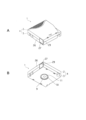
- FIG. 1A and 1B are overall perspective views of a tape cartridge according to an embodiment of the present technology, in which FIG. 1A is a perspective view as seen from above, and FIG. 1B is a perspective view as seen from below.
- FIG. 2 is an exploded perspective view of the tape cartridge.
- FIG. 2 is an exploded cross-sectional side view of the tape cartridge.
- FIG. 2 is a schematic cross-sectional side view of a tape reel.
- 1 is a schematic cross-sectional view illustrating the operation of a typical tape reel.
- 6 is a schematic diagram of a main portion of a magnetic tape for explaining a problem associated with the deformation of the tape reel shown in FIG. 5.
- 1 is a side cross-sectional view of a reel half that constitutes a tape reel according to a comparative example.
- FIG. 8 is an enlarged cross-sectional view of a main portion of a reel hub in the tape reel shown in FIG. 7.
- 8 is a schematic cross-sectional view illustrating the operation of the tape reel shown in FIG. 7.
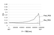
- 8 is a result of an experiment showing the recording and reproducing characteristics of a magnetic tape in a tape cartridge having the tape reel shown in FIG. 7.
- FIG. 8 is a conceptual diagram for explaining a problem with the tape cartridge having the tape reel shown in FIG. 7. 1 is a side cross-sectional view of a main portion of a tape reel according to an embodiment of the present technology. 13 is an enlarged cross-sectional view of a main portion of the tape reel shown in FIG. 12.
- FIG. 13 is a side cross-sectional view of a main portion of a tape reel according to another embodiment of the present technology.
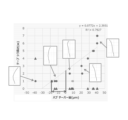
- 1 is a result of an experiment showing the relationship between the amount of hub taper of a tape reel (horizontal axis) and the height of deformation wrinkles that occur at the edge of a magnetic tape (vertical axis).
- FIG. 4 is a diagram showing an external profile of a reel hub.
- FIG. 4 is a diagram showing a method for measuring the outer profile.
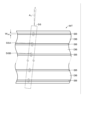
- FIG. 1 is a cross-sectional view showing an example of a configuration of a magnetic tape.
- FIG. 2 is a schematic diagram showing an example of a layout of a data band and a servo band.
- FIG. 4 is an enlarged view showing an example of the configuration of a data band.
- FIG. 2 is an enlarged view showing an example of a configuration of a servo band.
- FIG. 1 is an overall perspective view of a tape cartridge 1 according to one embodiment of the present technology, where A is a perspective view seen from the top (upper shell 2) side, and B is a perspective view seen from the bottom (lower shell 3) side.
- FIG. 2 is an exploded perspective view of the tape cartridge 1
- FIG. 3 is an exploded cross-sectional side view thereof.
- the tape cartridge 1 of this embodiment has a configuration in which a single tape reel 5 around which a magnetic tape MT is wound is rotatably housed inside a cartridge case 4 formed by joining an upper shell 2 and a lower shell 3 with a plurality of screw members.
- the tape cartridge 1 of this embodiment will be described below using a magnetic tape cartridge conforming to the LTO (Linear Tape Open) standard as an example.
- the tape reel 5 has a cylindrical reel hub 6 with a bottom, a lower flange 7 integrally formed with the lower end of the reel hub 6, and an upper flange 8 joined to the upper end of the reel hub 6, each of which is made from an injection molded synthetic resin material.
- a chucking gear 9 is formed in an annular shape in the center of the underside of the tape reel 5, which engages with the reel rotation drive shaft of the recording/playback device (drive), and is exposed to the outside through an opening 10 provided in the center of the lower shell 3, as shown in FIG. 1B.
- an annular metal plate 11 that magnetically attracts the reel rotation drive shaft is fixed to the bottom outer surface of the reel hub 6 by insert molding.
- a reel lock mechanism is provided inside the reel hub 6 to prevent the tape reel 5 from rotating when the tape cartridge 1 is not in use.
- the reel lock mechanism includes a plurality of gear forming walls 12 erected on the upper surface of the bottom 60 of the reel hub 6, a reel lock member 13 having engagement teeth 13a that mesh with a gear portion 12a formed on the upper surface of the gear forming walls 12, a reel lock release member 14 for releasing the engagement between the gear forming walls 12 and the reel lock member 13, and a reel spring 15 provided between the inner surface of the upper shell 2 and the upper surface of the reel lock member 13.
- the reel spring 15 is a coil spring, and biases the tape reel 5 toward the lower shell 3 via the reel lock member 13.
- the gear forming wall 12 has an arc shape and is formed on the upper surface of the bottom 60 of the reel hub 6 at three equally spaced locations on the same circumference around the axis of the reel hub 6.
- the engagement teeth 13a of the reel lock member 13 that face the gear portion 12a of the gear forming wall 12 are formed in an annular shape on the lower surface of the reel lock member 13 and are constantly biased in the direction of engagement with the gear portion 12a by receiving a reel spring 15.
- An engagement protrusion 13c is formed on the upper surface of the reel lock member 13, and an engagement recess 2a that fits into this engagement protrusion 13c is formed in the approximate center of the inner surface of the upper shell 2.
- the reel lock release member 14 has a roughly triangular shape and is disposed between the bottom 60 of the reel hub 6 and the reel lock member 13.
- a total of three legs 14a are formed on the underside of the reel lock release member 14, protruding downward from each apex of the roughly triangular shape, and these legs are positioned between the gears of the chucking gear 9 via insertion holes 61 formed in the bottom 60 of the reel hub 6 when the cartridge is not in use.
- One side wall 26 of the cartridge case 4 is provided with a pull-out opening 27 for pulling out one end of the magnetic tape MT to the outside.
- a sliding door 29 for opening and closing the pull-out opening 27 is disposed inside the side wall 26.
- the sliding door 29 is configured to slide in a direction that opens the pull-out opening 27 against the biasing force of the torsion spring 57 by engaging with a tape loading mechanism (not shown) of the recording/playback device.
- a leader pin 31 is fixed to one end of the magnetic tape MT.
- the leader pin 31 is configured to be detachable from a pin holding portion 33 provided on the inside side of the pull-out opening 27.
- the pin holding portions 33 are attached to the inner surface of the upper shell 2 and the inner surface of the lower shell 3, respectively, and are configured to be able to elastically hold the upper and lower ends of the leader pin 31, respectively.
- the cartridge memory 54 is made up of a contactless communication medium that has an antenna coil, IC chip, etc. mounted on a substrate.
- the tape reel 5 has a reel hub 6, a lower flange 7 as a first flange, and an upper flange 8 as a second flange.
- the lower flange 7 is integrally formed with the lower end (first end) of the reel hub 6, and the upper flange 8 is joined to the upper end (second end) of the reel hub 6 by ultrasonic bonding or the like.
- the reel hub 6 has a generally cylindrical shape, and its axial height is slightly larger than the width (12.65 mm) of the magnetic tape MT, being approximately 13 mm (12.87 mm).
- the inner diameter of the reel hub 6 is approximately 40 mm (39.6 mm), and its wall thickness, which is the thickness dimension in the radial direction, is approximately 2 mm.
- the reel hub 6 and the lower flange 7 are integrally molded using synthetic resin materials such as PC (polycarbonate) and ABS (acrylonitrile butadiene styrene).
- the upper flange 8 is also molded using synthetic resin materials such as PC and ABS.
- the molding material for the reel hub 6 and the lower flange 7 may be a composite material in which an inorganic filler such as glass filler is added to the above synthetic resin material for the purpose of improving strength.
- the weight ratio of the glass filler is not particularly limited, and is, for example, about 10% to 30% by weight of the base synthetic resin material. In this embodiment, a composite material containing 10% to 20% by weight of glass filler in polycarbonate resin is used as the molding material for the reel hub 6.
- the reel hub 6 has a cylindrical shape with a constant thickness from the lower end 6a, which is formed integrally with the lower flange 7, to the upper end 6b, which is joined to the upper flange 8.
- the upper flange 8 is positioned by fitting an annular protrusion 8b, which is formed along the periphery of an opening 8a provided in the center, into the inner peripheral surface of the upper end 6b of the reel hub 6.
- the reel hub 6 is ultrasonically joined to the upper flange 8 directly above the upper end 6b.
- the outer peripheral surface 6d of the reel hub 6 functions as a winding surface on which the magnetic tape MT is wound.
- the outer peripheral surface 6c is typically a flat cylindrical surface.
- the outer peripheral surface 6c of the reel hub 6 is pressed radially inward due to the tightening (winding pressure) of the magnetic tape MT.
- the rigidity of the upper end 6b side of the reel hub 6 is lower than that of the lower end 6a side, so that, as shown somewhat exaggeratedly in Figure 5, the winding pressure of the magnetic tape MT acts as a pressing force that tilts the upper end 6b of the reel hub 6 radially inward (see arrow A).
- Figure 7 is a side cross-sectional view of a reel half 67 in which a reel hub 6 and a lower flange 7 are integrally formed according to the comparative example
- Figure 8 is an enlarged cross-sectional view of a main portion thereof.
- the reel hub 6 has a lower end 6a (first end) formed integrally with the lower flange 7 (first flange), an upper end 6b (second end) to which the upper flange 8 is joined, a hub outer peripheral surface 6d around which the magnetic tape MT is wound, and a hub inner peripheral surface 6e.
- the hub outer circumferential surface 6d has a first outer circumferential region 6d1 and a second outer circumferential region 6d2, as shown in an enlarged view in Fig. 8.
- the hub inner circumferential surface typically has a flat cylindrical surface shape.
- the ridge portion 6d3 has a shape that is convex toward the radially outward direction of the reel hub 6.
- the taper angle of the first outer peripheral region 6d1 (the angle formed by the line segment connecting the outer peripheral edge portion P1 of the lower end portion 6a of the reel hub 6 and the ridge portion 6d3 with respect to the axis C1)
- the taper angle of the second outer peripheral region 6d2 (the angle formed by the line segment connecting the outer peripheral edge portion P2 of the upper end portion 6b of the reel hub 6 and the ridge portion 6d3 with respect to the axis C1) is ⁇ 2
- the relationship ⁇ 1> ⁇ 2 is satisfied.
- the ridge portion 6d3 is located closer to the bottom end 6a of the reel hub 6 than the center of the height H (12.87 mm) of the reel hub 6.
- the height H1 from the bottom end 6a of the reel hub 6 is 3 mm or more and 5 mm or less.
- the difference ⁇ R1 between the radius of the ridge portion 6d3 centered on the axis C1 and the radius of the outer periphery P1 is 5 ⁇ m or more and 25 ⁇ m or less.
- the difference ⁇ R2 between the radius of the bottom end 6a of the reel hub 6 centered on the axis C1 and the radius of the top end 6b of the reel hub 6 is 15 ⁇ m or more and 45 ⁇ m or less.
- the thickness of the lower end 6a becomes smaller than the thickness of the upper end 6b. Therefore, when the winding pressure of the magnetic tape MT acts on the reel hub 6, or during long-term storage in a high-temperature, high-humidity environment, the reel hub 6 is likely to deform radially inward over its entire height direction due to bending stress with the connection area between the lower end 6a of the reel hub 6 and the lower flange 7 as a fulcrum.
- the lower edge portion 22a of the magnetic tape MT is in close contact with the first outer peripheral region 161 of the reel hub 6 after deformation due to the winding pressure of the magnetic tape MT, thereby suppressing deformation of the lower edge portion 22a as shown in FIG. 5.
- the upper end portion 6b of the reel hub 6 is suppressed from falling radially inward as shown in FIG. 5, and the center portion of the height direction of the reel hub 6 can be deformed to have a curved shape that is convex radially inward as shown in FIG. 9. This prevents the occurrence of deformation wrinkles such as those shown in Figure 6 on the lower edge portion 22a of the magnetic tape MT, ensuring stable recording and playback characteristics.
- the tape reel according to the comparative example is effective in preventing the occurrence of the above-mentioned deformation and wrinkles in the magnetic tape MT during long-term storage in a high-temperature, high-humidity environment, it was confirmed that if the magnetic tape MT is not stored for a long period of time in the above-mentioned environment, deformation of the magnetic tape MT and deterioration of its running performance occur due to the shape of the hub outer peripheral surface 6d.
- Figure 10 shows the average standard deviation ( ⁇ PES) of the PES (Position Error Signal) values detected when the magnetic tape MT is run in the Fwd and Rvs directions using a tape cartridge 1 immediately after manufacture.
- ⁇ PES average standard deviation
- the Fwd direction refers to the direction in which the magnetic tape MT is unwound from the tape reel 5 of the tape cartridge 1 to the take-up reel of the recording and playback device
- the Rvs direction refers to the direction in which the magnetic tape MT is wound from the take-up reel of the recording and playback device to the tape reel 5 of the tape cartridge 1.
- the PES value does not fluctuate significantly and can be stably maintained at the target PES value, whereas in the Fwd direction, the PES value tends to increase as the running length of the magnetic tape MT increases. The following reasons are thought to be the cause of this.
- the hub outer circumferential surface 6d is formed in a tapered shape expanding in diameter from the lower end 6a to the upper end 6b as shown in FIG. 8, the magnetic tape MT unwound from the reel hub 6 is unwound in an oblique direction toward the upper flange 8 as shown in FIG. 11.
- the upper edge portion 22a of the magnetic tape MT is in contact with the inner surface of the upper flange 8 as it is wound onto the take-up reel of the recording and playback device.
- the area near the EOT of the magnetic tape MT is the area where the winding pressure on the reel hub 6 is the highest, so the shape of the hub outer circumferential surface 6d described above is likely to cause a difference in the tension balance between the top and bottom of the reel hub 6. For this reason, compressive stress occurs on the lower flange 7 side (the lower end 6a side of the reel hub 6) where the hub diameter is smaller, causing the lower edge portion 22a of the magnetic tape MT to shrink and deform in the longitudinal direction, which is thought to be the cause of the deterioration of the PES value.
- the reel hub 6 is configured as follows to achieve stable recording and playback characteristics while suppressing deformation of the magnetic tape. Details of this embodiment are described below.
- the tape reel of this embodiment includes a lower flange 7 (first flange), an upper flange 8 (second flange), and a cylindrical reel hub 6.
- Fig. 12 is a side cross-sectional view of a reel half 71 in which the reel hub 6 and the lower flange 7 are integrally formed according to a first configuration example of this embodiment, and
- Fig. 13 is an enlarged cross-sectional view of a main portion of the reel hub 6.
- the reel hub 6 has a lower end 6a (first end) that is integrally formed with the lower flange 7 (first flange), an upper end 6b (second end) to which the upper flange 8 is joined, an outer circumferential surface (hereinafter also referred to as the hub outer circumferential surface) 16 on which the magnetic tape MT is wound, and an inner circumferential surface 6e.
- the inner circumferential surface 6e of the reel hub 6 typically has a flat cylindrical surface shape.
- the hub outer peripheral surface 16 has a first outer peripheral region 161 and a second outer peripheral region 162, as shown enlarged in FIG. 13.
- the first outer peripheral region 161 is a region that expands in diameter from the lower end 6a to the upper end 6b of the reel hub 6.
- the shape of the first outer peripheral region 161 is not particularly limited as long as it expands in diameter from the lower end 6a to the upper end 6b.
- the first outer peripheral region 161 may be a linear tapered surface or may be formed as a curved surface.
- the shape of the curved surface may be a bulging surface that is convex toward the radially outward direction of the reel hub 6, a recessed surface that is convex toward the radially inward direction of the reel hub 6, or a composite curved surface that includes these bulging and recessed surfaces.
- the surface shape of the first outer peripheral region 161 can be arbitrarily adjusted according to the molding conditions of the reel hub 6 (molding material, molding temperature, surface properties of the molding die, etc.).
- the magnitude of ⁇ 1 is set so that the difference between the outer diameter of the reel hub 6 at the ridge 91 and the outer diameter of the reel hub 6 at the outer peripheral edge P1 is, for example, 10 ⁇ m or more and 50 ⁇ m or less.
- the second outer peripheral region 162 is a region that extends from the first outer peripheral region 161 toward the upper end 6b of the reel hub 6, and forms a ridge portion 91 (first ridge portion) on the boundary with the first outer peripheral region 161.
- the second outer flow region 162 is formed from the first outer peripheral region 161 to the upper end 6b of the reel hub 6.
- the second outer peripheral region 162 extends in a straight cylindrical shape from the ridge portion 91 toward the upper end 6b of the reel hub 6.
- Straight cylindrical shape means that it is straight and parallel to the axis C1 of the reel hub 6, and the angle ⁇ 2 in FIG. 8 is 0° or approximately 0°.
- the second outer peripheral region 162 is a linear cylindrical surface, but may be inclined toward the outer diameter side or inner diameter side of the reel hub 6 at an angle sufficiently smaller than the taper angle ⁇ 1 of the first outer peripheral region 161.
- the surface shape of the second outer peripheral region 162 can be adjusted as desired depending on the molding conditions of the reel hub 6 (molding material, molding temperature, surface properties of the molding die, etc.).
- the ridge portion 91 has a shape that is convex toward the radially outward direction of the reel hub 6.
- the ridge portion 91 corresponds to an inclination inflection point that connects the first outer circumferential region 161 and the second outer circumferential region 162.
- the cross-sectional shape of the ridge portion 91 along the axis C1 is not particularly limited, and may be a corner portion formed between the first outer circumferential region 161 and the second outer circumferential region 162, or a curved surface formed between them.
- the thickness of the lower end 6a of the reel hub 6 is smaller than the thickness of the upper end 6b. Therefore, when the winding pressure of the magnetic tape MT acts on the reel hub 6, or when it is stored for a long period of time in a high-temperature and high-humidity environment, the reel hub 6 is likely to deform radially inward over its entire height due to bending stress with the connection area between the lower end 6a of the reel hub 6 and the lower flange 7 as a fulcrum.
- the lower edge portion 22a of the magnetic tape MT is in close contact with the first outer peripheral region 161 of the reel hub 6 after deformation due to the winding pressure of the magnetic tape MT, thereby suppressing deformation of the lower edge portion 22a as shown in FIG. 5. This prevents the occurrence of deformation wrinkles as shown in FIG. 6 on the lower edge portion 22a of the magnetic tape MT, ensuring stable recording and playback characteristics of the magnetic tape MT.
- the running direction of the magnetic tape MT unwound from the reel hub 6 becomes a direction perpendicular to the axis C1 of the reel hub 6 (horizontal direction). This improves the straight running properties of the magnetic tape MT and prevents rubbing winding where the upper edge portion 22b comes into contact with the upper flange 8, so the PES value can be kept below a certain level over the entire length of the magnetic tape MT not only when it is running in the Rvs direction but also when it is running in the FwD direction.
- the second outer peripheral region 162 is formed in a straight cylindrical shape, it is possible to reduce the difference in tension in the tape length direction of both edge portions 22a, 22b of the magnetic tape MT on the hub outer peripheral surface 16. This makes it possible to suppress the occurrence of deformation wrinkles due to shrinkage deformation of the lower edge portion 22a facing the first outer peripheral region 161, which contributes to stable recording and playback characteristics.
- the ridge portion 91 is located closer to the bottom end 6a of the reel hub 6 than the center of the height H (12.87 mm) of the reel hub 6.
- the height H1 from the bottom end 6a of the reel hub 6 is 3 mm or more and 5 mm or less. If the height H1 is less than 3 mm, the above-mentioned action of this embodiment may not be effectively achieved. Furthermore, if the height H1 exceeds 5 mm, the releasability of the molding die that forms the hub outer peripheral surface 16 may decrease.
- the height H1 By setting the height H1 to 3 mm or more and 5 mm or less, it is possible to ensure good moldability of the reel hub 6 while ensuring the storage properties of the tape cartridge 1, that is, stable recording and playback characteristics even after long-term storage in a high-temperature, high-humidity environment.
- the difference ⁇ R1 between the radius of the ridge portion 91 centered on the axis C1 and the radius of the outer peripheral edge portion P1 is 5 ⁇ m or more and 25 ⁇ m or less.
- the difference between the outer diameter of the ridge portion 91 and the outer diameter of the lower end portion 6a of the reel hub 6 is 10 ⁇ m or more and 50 ⁇ m or less. This allows the ridge portion 6d3 to be stably formed at the height H1.
- the outer diameter of the upper end portion 6b is the same or nearly the same as the outer diameter of the ridge portion 91, and preferably, the outer diameter of the upper end portion 6b is equal to or smaller than the outer diameter of the ridge portion 91.
- (Configuration Example 2) 14 is an enlarged cross-sectional view of a main portion of a reel half 72 in which the reel hub 6 and the lower flange 7 are integrally formed according to Configuration Example 2 of the present embodiment. Note that, since the configuration example is the same as the above-mentioned Configuration Example 1 except for the shape of the hub outer circumferential surface 16, differences from Configuration Example 1 will mainly be described here.
- the hub outer peripheral surface 16 has a first outer peripheral region 161, a second outer peripheral region 162, and a third outer peripheral region 163, as shown in FIG. 14.
- the first outer circumferential region 161 is a region whose diameter increases from the lower end 6a to the upper end 6b of the reel hub 6.
- the second outer circumferential region 162 is a region that extends in a straight cylindrical shape from the first outer circumferential region 161 toward the upper end 6b of the reel hub 6, and forms a first ridge portion 91 on the boundary with the first outer circumferential region 161.
- the third outer peripheral region 163 is a region that narrows from the second outer peripheral region 162 to the upper end 6b of the reel hub 6, and forms a second ridge portion 92 that is convex toward the outside diameter of the reel hub 6 on the boundary with the second outer peripheral region 162.
- the shape of the third outer circumferential region 163 is not particularly limited as long as it is tapered from the second ridge portion 92 to the upper end 6b of the reel hub 6.
- the third outer circumferential region 163 may be a linear tapered surface, or may be formed as a curved surface.
- the shape of the curved surface may be a bulging surface that is convex toward the outside of the reel hub 6, a recessed surface that is convex toward the inside of the reel hub 6, or a composite curved surface that includes these bulging and recessed surfaces.
- the surface shape of the third outer circumferential region 163 can be adjusted as desired depending on the molding conditions of the reel hub 6 (molding material, molding temperature, surface properties of the molding die, etc.).
- the second ridge portion 92 corresponds to an inflection point at which the second outer periphery region 162 and the third outer periphery region 163 are connected.
- the cross-sectional shape of the second ridge portion 92 along the axis C1 direction is not particularly limited, and may be a corner portion formed between the second outer periphery region 162 and the third outer periphery region 163, or a curved surface formed between them.
- the tension difference in the tape length direction of both edge portions 22a, 22b of the magnetic tape MT on the hub outer peripheral surface 16 can be further alleviated. This makes it less likely that deformation wrinkles due to shrinkage deformation will occur in the lower edge portion 22a facing the first outer peripheral region 161, thereby enabling further improvement of the PES value.
- the outer diameter of the upper end 6b of the reel hub 6 is equal to or smaller than the outer diameter of the first ridge 91, and in this particular configuration example, the taper angle ⁇ 3 of the third outer peripheral region 163 is set so that the outer diameter of the upper end 6b is smaller than the outer diameter of the first ridge 91 and the outer diameter of the second ridge 92. In this configuration example, the angle ⁇ 3 is set so that the outer diameter of the upper end 6b is equal to or smaller than the outer diameter of the lower end 6a.
- the angle ⁇ 3 is the angle between the axis C1 and the line segment connecting the second ridge P2 and the outer peripheral edge P2 of the upper end 6b of the reel hub 6.
- the taper angle ⁇ 1 of the first outer peripheral region 161 and the taper angle ⁇ 3 of the third outer peripheral region 163 are angles with opposite positive and negative values.
- the magnitude of the angle ⁇ 3 can be adjusted by the height H2 from the lower end 6a of the second ridge portion 92, and in this configuration example, it is set so that the outer diameter of the upper end 6b is smaller than the outer diameter of the second ridge portion 92.
- the height H2 of the second ridge portion 92 is not particularly limited as long as it is greater than the height H1 of the first ridge portion 91, and is, for example, 6 mm or more and 9 mm or less.
- the height (H-H2) from the second ridge 92 to the upper end 6b of the reel hub 6 may be greater or less than the height H1 from the lower end 6a of the reel hub 6 to the first ridge 91.
- the second ridge 92 may be located at the center of the height of the reel hub 6 or closer to the lower end 6a than that center, or closer to the upper end 6b.
- the hub outer peripheral surface 16 is formed with a shape in which the central region in the height direction (second outer peripheral region 162) is convex radially outward.
- the magnetic tape MT wound around the hub outer peripheral surface 16 is curved with its central region in the width direction convex radially outward of the reel hub 6. This reduces the difference in tension in the tape longitudinal direction between both edge portions 22a, 22b of the magnetic tape MT, effectively suppressing deterioration of the PES value due to deformation and wrinkling of the magnetic tape MT.
- (evaluation) 15 shows the results of an experiment showing the relationship between the difference (the hub taper amount on the horizontal axis) obtained by subtracting the radius of the upper end 6b from the radius of the second ridge 92 of the reel hub 6, and the height of the deformation wrinkles (the width of the wrinkles formed along the tape width direction) of the edges 22a, 22b of the magnetic tape MT.
- the plots shown with circles indicate the wrinkles on the lower edge 22a side
- the plots shown with triangles indicate the wrinkles on the upper edge 22b side.
- the shape profile (gradient waveform) superimposed in the figure shows the trace shape of the hub outer circumferential surface 16.
- FIG. 16 shows the shape profile of the outer circumferential surface of the hub for the comparative example and configuration examples 1 and 2.
- the first outer circumferential region has the same design.
- the shape profile of the outer circumferential surface of the hub for the basic shape is also shown in the figure.
- FIG. 17 is an explanatory diagram showing a method for measuring the shape profile of the hub outer circumferential surface 16.
- the measurement procedure is as follows. First, the chucking gear 9 (see FIG. 1B) at the bottom of the reel hub 6 is set on a jig (master gear) on a rotating table (not shown), and the reel half 67 is rotatably supported. With the reel half 67 stopped, a probe 81 (diameter 1.6 mm) is brought into contact with the outer circumferential surface 6d of the reel hub 6, and the probe 81 is traced up and down to measure the gradient of the outer circumferential surface 6d.
- the origin of the measurement is set to a position 1 mm above the lower end 6a of the reel hub 6, and the measurement length is set to 11 mm.
- the measurement machine used was a "Mitutoyo Roundtest RA-2100" manufactured by Mitutoyo Corporation. After tracing with the probe 81, the rotary table was rotated 30° and the same measurement as above was performed. This operation was repeated 12 times to perform measurements at 12 locations in the circumferential direction of the reel hub 6. The average value of the measured waveforms at the 12 locations was taken as the shape profile (gradient waveform) of the hub outer circumferential surface 16.
- the preferred range of the hub taper amount is -18 ⁇ m or more and 0 ⁇ m or less. If the hub taper amount is greater than -18 ⁇ m in the negative direction, there is a risk that the deformation of the upper edge portion 22b will increase when the magnetic tape MT is wound up. For this reason, considering the impact on the reliability of the magnetic tape MT, it is preferable that the hub taper amount be -18 ⁇ m or more and 0 ⁇ m or less.
- FIG. 18 is a cross-sectional view showing an example of the configuration of the magnetic tape MT.
- the magnetic tape MT includes a long substrate 41, an underlayer 42 provided on one main surface (first main surface) of the substrate 41, a magnetic layer 43 provided on the underlayer 42, and a back layer 44 provided on the other main surface (second main surface) of the substrate 41.
- the underlayer 42 and the back layer 44 are provided as necessary and may not be required.
- the magnetic tape MT is an example of a tape-shaped magnetic recording medium.
- the magnetic tape MT may be a perpendicular recording type magnetic recording medium or a longitudinal recording type magnetic recording medium.
- the magnetic tape MT preferably contains a lubricant from the viewpoint of improving running properties.
- the lubricant may be included in at least one layer of the underlayer 42 and the magnetic layer 43.
- the magnetic tape MT may be one that complies with the LTO standard, or one that complies with a standard other than the LTO standard.
- the width of the magnetic tape MT may be 1/2 inch, or may be wider than 1/2 inch. If the magnetic tape MT complies with the LTO standard, the width of the magnetic tape MT is 1/2 inch.
- the magnetic tape MT may have a configuration that allows the width of the magnetic tape MT to be kept constant or nearly constant by adjusting the tension applied to the magnetic tape MT in the longitudinal direction during running using a recording and playback device (drive).
- the magnetic tape MT may be housed in a one-reel type cartridge or a two-reel type cartridge to form a magnetic tape cartridge.
- the magnetic tape MT is long and runs in the longitudinal direction during recording and playback.
- the magnetic tape MT is preferably used in a recording and playback device equipped with a ring-type head as a recording head.
- the magnetic tape MT is preferably used in a recording and playback device configured to be able to record data with a data track width of 1000 nm or less.
- the magnetic tape MT is preferably reproduced by a reproduction head using a TMR element.
- the signal reproduced by the reproduction head using TMR may be data recorded in the data band DB (see FIG. 19) or a servo pattern (servo signal) recorded in the servo band SB (see FIG. 19).
- the substrate 41 is a non-magnetic support that supports the underlayer 42 and the magnetic layer 43.
- the substrate 41 has a long film shape.
- the upper limit of the average thickness of the substrate 41 is preferably 4.40 ⁇ m or less, more preferably 4.20 ⁇ m or less, even more preferably 4.00 ⁇ m or less, 3.80 ⁇ m or less, or 3.40 ⁇ m or less.
- the lower limit of the average thickness of the substrate 41 is preferably 3.00 ⁇ m or more, more preferably 3.20 ⁇ m or more.
- the lower limit of the average thickness of the substrate 41 is 3.00 ⁇ m or more, the strength reduction of the substrate 41 can be suppressed.
- the average thickness of the substrate 41 is determined as follows. First, the magnetic tape MT contained in the cartridge 1 is unwound, and a sample is prepared by cutting the magnetic tape MT to a length of 250 mm at a position 30 to 40 m in the longitudinal direction from one end of the outer periphery of the magnetic tape MT.
- longitudinal direction when referring to "the longitudinal direction from one end of the outer periphery of the magnetic tape MT” means the direction from one end of the outer periphery of the magnetic tape MT toward the other end of the inner periphery.
- the layers of the sample other than the substrate 41 i.e., the underlayer 42, the magnetic layer 43, and the back layer 44
- a solvent such as MEK (methyl ethyl ketone) or dilute hydrochloric acid.
- the thickness of the sample (substrate 41) is measured at five positions using a Mitutoyo Laser Hologram (LGH-110C) as a measuring device, and the average thickness of the substrate 41 is calculated by simply averaging (arithmetic mean) these measurements. Note that the five measurement positions are selected randomly from the sample so that they are each different positions in the longitudinal direction of the magnetic tape MT.
- the base 41 contains, for example, a polyester-based resin as a main component.
- the polyester-based resin contains, for example, at least one selected from the group consisting of PET (polyethylene terephthalate), PEN (polyethylene naphthalate), PBT (polybutylene terephthalate), PBN (polybutylene naphthalate), PCT (polycyclohexylene dimethylene terephthalate), PEB (polyethylene-p(oxybenzoate)), and polyethylene bisphenoxycarboxylate.
- PET polyethylene terephthalate
- PEN polyethylene naphthalate
- PBT polybutylene terephthalate
- PBN polybutylene naphthalate
- PCT polycyclohexylene dimethylene terephthalate
- PEB polyethylene-p(oxybenzoate)
- polyethylene bisphenoxycarboxylate polyethylene bisphenoxycarboxylate.
- the base 41 may contain two or more types of polyester-based resin
- the term "main component” means the component that is contained in the highest proportion among the components that constitute the base 41.
- the content of the polyester-based resin in the base 41 may be, for example, 50% by mass or more, 60% by mass or more, 70% by mass or more, 80% by mass or more, 90% by mass or more, 95% by mass or more, or 98% by mass or more relative to the mass of the base 41, or the base 41 may be composed only of a polyester-based resin.
- the substrate 41 contains polyester-based resin can be confirmed, for example, as follows. First, similar to the method for measuring the average thickness of the substrate 41, a magnetic tape MT is prepared and cut to a length of 250 mm to prepare a sample, and then layers of the sample other than the substrate 41 are removed. Next, an IR spectrum of the sample (substrate 41) is obtained by infrared absorption spectrometry (IR). Based on this IR spectrum, it can be confirmed that the substrate 41 contains polyester-based resin.
- IR infrared absorption spectrometry
- the substrate 41 preferably contains a polyester-based resin.
- the Young's modulus in the longitudinal direction of the substrate 41 can be reduced to preferably 2.5 GPa or more and 7.8 GPa or less, more preferably 3.0 GPa or more and 7.0 GPa or less. Therefore, by adjusting the tension in the longitudinal direction of the magnetic tape MT during running using a recording/playback device, the width of the magnetic tape MT can be kept constant or almost constant. A method for measuring the Young's modulus in the longitudinal direction of the substrate 41 will be described later.
- the base 41 may contain a resin other than polyester-based resin.
- the resin other than polyester-based resin may be the main component of the constituent material of the base 41.
- the content ratio of the resin other than polyester-based resin in the base 41 may be, for example, 50 mass% or more, 60 mass% or more, 70 mass% or more, 80 mass% or more, 90 mass% or more, 95 mass% or more, or 98 mass% or more relative to the mass of the base 41, or the base 41 may be composed only of a resin other than polyester-based resin.
- polymer resins include, for example, at least one selected from the group consisting of PEEK (polyetheretherketone), PA (polyamide, nylon), aromatic PA (aromatic polyamide, aramid), PI (polyimide), aromatic PI (aromatic polyimide), PAI (polyamideimide), aromatic PAI (aromatic polyamideimide), PBO (polybenzoxazole, e.g.
- Zylon (registered trademark)), polyether, PEK (polyetherketone), polyetherester, PES (polyethersulfone), PEI (polyetherimide), PSF (polysulfone), PPS (polyphenylene sulfide), PC (polycarbonate), PAR (polyarylate), and PU (polyurethane).
- the base 41 may contain PEEK (polyetheretherketone), PA (polyamide, nylon), aromatic PA (aromatic polyamide, aramid), PI (polyimide), aromatic PI (aromatic polyimide), PAI (polyamideimide), aromatic PAI (aromatic polyamideimide), PBO (polybenzoxazole, for example Zylon (registered trademark)), polyether, PEK (polyetherketone), polyetherester, PES (polyethersulfone), PEI (polyetherimide), PSF (polysulfone), PPS (polyphenylene sulfide), PC (polycarbonate), PAR (polyarylate), or PU (polyurethane) as a main component.
- PEEK polyetheretherketone
- PA polyamide, nylon
- aromatic PA aromatic polyamide, aramid
- PI polyimide
- PAI polyamideimide
- PAI aromatic PAI (aromatic polyamideimide)
- PBO poly
- the substrate 41 may be biaxially stretched in the longitudinal and width directions.
- the polymer resin contained in the substrate 41 is preferably oriented in a direction oblique to the width direction of the substrate 41.
- the magnetic layer 43 is configured to be capable of recording signals by a magnetization pattern.
- the magnetic layer 43 may be a perpendicular recording type recording layer or a longitudinal recording type recording layer.
- the magnetic layer 43 includes, for example, a magnetic powder and a binder.
- the magnetic layer 43 may further include at least one additive selected from the group consisting of conductive particles, lubricants, abrasive particles, hardeners, rust inhibitors, and non-magnetic reinforcing particles, as necessary.
- the magnetic layer 43 may have a plurality of protrusions on the surface (magnetic surface) on the magnetic layer 43 side. The plurality of protrusions are formed, for example, by conductive particles and abrasive particles protruding from the magnetic surface.
- the magnetic layer 43 may already have a plurality of servo bands SB and a plurality of data bands DB, as shown in FIG. 19.
- the plurality of servo bands SB are arranged at equal intervals in the width direction of the magnetic tape MT.
- a data band DB is provided between adjacent servo bands SB.
- the servo bands SB are for guiding the head unit (magnetic head) 56 (specifically, servo read heads 56A, 56B) when recording or reproducing data.
- a servo pattern (servo signal) for tracking control of the head unit 56 is written in advance in the servo bands SB. User data is recorded in the data bands DB.
- the head unit 56 may be configured to be able to maintain an angle with respect to an axis Ax parallel to the width direction of the magnetic tape MT when recording and reproducing data, as shown in FIG. 19.
- the head unit 56 may be configured to follow the meandering or deformation of the magnetic tape MT and become angled with respect to the axis Ax when recording and reproducing data.
- the inclination angle of the head unit 56 with respect to the axis Ax parallel to the width direction of the magnetic tape MT is preferably 3° or more and 18° or less, more preferably 5° or more and 15° or less.
- the lower limit of the ratio R S of the total area S SB of the plurality of servo bands SB to the area S of the magnetic surface is preferably 1.0% or more, from the viewpoint of ensuring 5 or more servo bands SB.
- the ratio R of the total area S of the servo bands SB to the area S of the entire magnetic surface is calculated as follows:
- the magnetic tape MT is developed using a ferricolloid developer (Sigma Marker Q, manufactured by Sigma High Chemical Co., Ltd.), and then the developed magnetic tape MT is observed under an optical microscope to measure the servo band width W and the number of servo bands SB.
- the number of servo bands SB is, for example, 5+4n (where n is an integer equal to or greater than 0) or more.
- the number of servo bands SB is calculated in the same manner as the ratio RS described above.
- the upper limit of the servo band width WSB is preferably 95 ⁇ m or less, more preferably 65 ⁇ m or less, and even more preferably 50 ⁇ m or less.
- the lower limit of the servo band width WSB is preferably 10 ⁇ m or more. It is difficult to manufacture a magnetic head capable of reading a servo signal with a servo band width WSB of less than 10 ⁇ m.
- the width of the servo band width WSB is calculated in the same manner as the ratio RS described above.
- the magnetic layer 43 is configured to allow multiple data tracks Tk to be formed in the data band DB.
- the upper limit of the data track width W is preferably 800 nm or less, more preferably 600 nm or less, and even more preferably 450 nm or less, 300 nm or less, or 150 nm or less.
- the lower limit of the data track width W is preferably 20 nm or more.
- the data track width W is obtained as follows. First, a cartridge 1 with data recorded on the entire surface of the magnetic tape MT is prepared, the magnetic tape MT is unwound from the cartridge 1, and the magnetic tape MT is cut into a length of 250 mm at a position 30 to 40 m in the longitudinal direction from one end of the outer periphery of the magnetic tape MT to prepare a sample. Next, the data recording pattern of the data band DB part of the magnetic layer 43 of the sample is observed using a magnetic force microscope (MFM) to obtain an MFM image. Buker's Dimension ICON and its analysis software are used as the MFM.
- MFM magnetic force microscope
- the analysis software provided with the Dimension ICON is used to measure the track width.
- the measurement conditions for the above MFM are sweep speed: 1 Hz, chip used: MFMR-20, lift height: 20 nm, correction: Flatten order 3.
- the magnetic layer 43 is configured to be capable of recording data such that the minimum distance Lmin between magnetization reversals is preferably 47 nm or less, more preferably 44 nm or less, even more preferably 40 nm or less, and particularly preferably 37 nm or less.
- the lower limit of the minimum distance Lmin between magnetization reversals is preferably 20 nm or more.
- the servo pattern is a magnetized region, and is formed by magnetizing a specific region of the magnetic layer 43 in a specific direction with a servo write head during magnetic tape manufacturing.
- the region of the servo band SB where the servo pattern is not formed (hereinafter referred to as the "non-pattern region") may be a magnetized region where the magnetic layer 43 is magnetized, or a non-magnetized region where the magnetic layer 43 is not magnetized.
- the non-pattern region is a magnetized region
- the servo pattern forming region and the non-pattern region are magnetized in different directions (e.g., opposite directions).
- the servo band SB has a servo pattern formed thereon consisting of multiple servo stripes (linear magnetized regions) 113 inclined with respect to an axis Ax parallel to the width direction of the magnetic tape MT, as shown in FIG. 21.
- the servo band SB includes multiple servo frames 110.
- Each servo frame 110 is composed of 18 servo stripes 113.
- each servo frame 110 is composed of a servo subframe 1 (111) and a servo subframe 2 (112).
- Servo subframe 1 is composed of an A burst 111A and a B burst 111B.
- the B burst 111B is disposed adjacent to the A burst 111A.
- the A burst 111A has five servo stripes 113 formed at regular intervals and inclined at a predetermined angle ⁇ 1 with respect to an axis Ax parallel to the width direction of the magnetic tape MT. In FIG. 21, these five servo stripes 113 are indicated by the symbols A 1 , A 2 , A 3 , A 4 , and A 5 from the EOT (End Of Tape) to the BOT (Beginning Of Tape) of the magnetic tape MT.
- the B burst 111B has five servo stripes 113 formed at regular intervals and inclined at a predetermined angle ⁇ 2 with respect to an axis Ax parallel to the width direction of the magnetic tape MT.
- these five servo stripes 113 are indicated by the symbols B1 , B2 , B3 , B4 , and B5 from the EOT to the BOT of the magnetic tape MT.
- the servo stripes 113 of B burst 111B are inclined in the opposite direction to the servo stripes 113 of A burst 111A.
- the servo stripes 113 of A burst 111A and the servo stripes 113 of B burst 111B are asymmetric with respect to the axis Ax parallel to the width direction of the magnetic tape MT. In other words, the servo stripes 113 of A burst 111A and the servo stripes 113 of B burst 111B are arranged in a roughly V-shape.
- the servo stripes 113 of A burst 111A and the servo stripes 113 of B burst 111B are asymmetric with respect to the axis Ax, when the head unit 56 is inclined obliquely with respect to the axis Ax, there exists a state in which the servo stripes 113 of A burst 111A and the servo stripes 113 of B burst 111B are roughly symmetric with respect to the central axis of the sliding surface of the head unit 56.
- By changing the inclination of the head unit 56 based on this state it becomes possible to adjust the distance between the servo read heads 56A, 56B in the width direction of the magnetic tape MT.
- the servo read heads 56A, 56B can be made to face the specified positions of the servo band SB.
- the central axis of the sliding surface of the head unit 56 means the axis that passes through the centers of the multiple servo read heads 56A, 56B on the sliding surface of the head unit 56.
- the predetermined angle ⁇ 1 which is the inclination angle of the servo stripes 113 of the A burst 111A is different from the predetermined angle ⁇ 2 which is the inclination angle of the servo stripes 113 of the B burst 111B. More specifically, the predetermined angle ⁇ 1 of the servo stripes 113 of the A burst 111A may be larger than the predetermined angle ⁇ 2 of the servo stripes 113 of the B burst 111B, or the predetermined angle ⁇ 2 of the servo stripes 113 of the B burst 111B may be larger than the predetermined angle ⁇ 1 of the servo stripes 113 of the A burst 111A.
- the inclination of the servo stripes 113 of the A burst 111A may be larger than the inclination of the servo stripes 113 of the B burst 111B, or the inclination of the servo stripes 113 of the B burst 111B may be larger than the inclination of the servo stripes 113 of the A burst 111A.
- 21 shows an example in which the predetermined angle ⁇ 1 of the servo stripe 113 of the A burst 111A is larger than the predetermined angle ⁇ 2 of the servo stripe 113 of the B burst 111B.
- Servo subframe 2 (112) is composed of a C burst 112C and a D burst 112D.
- the D burst 112D is disposed adjacent to the C burst 112C.
- the C burst 112C has four servo stripes 113 formed at a specified interval and inclined at a specified angle ⁇ 1 with respect to an axis Ax parallel to the width direction of the magnetic tape MT. In Fig. 21, these four servo stripes 113 are indicated by the symbols C1 , C2 , C3 , and C4 from the EOT to the BOT of the magnetic tape MT.
- the D burst 112D has four servo stripes 113 formed at regular intervals and inclined at a predetermined angle ⁇ 2 with respect to an axis Ax parallel to the width direction of the magnetic tape MT.
- these four servo stripes 113 are indicated by the symbols D1 , D2 , D3 , and D4 from the EOT to the BOT of the magnetic tape MT.
- the servo stripes 113 of the D burst 112D are inclined in the opposite direction to the servo stripes 113 of the C burst 112C.
- the servo stripes 113 of the C burst 112C and the servo stripes 113 of the D burst 112D are asymmetric with respect to the axis Ax parallel to the width direction of the magnetic tape MT. That is, the servo stripes 113 of the C burst 112C and the servo stripes 113 of the D burst 112D are arranged in a substantially V-shape.
- the servo stripes 113 of the C burst 112C and the servo stripes 113 of the D burst 112D are asymmetric with respect to the axis Ax, when the head unit 56 is inclined obliquely with respect to the axis Ax, there exists a state in which the servo stripes 113 of the C burst 112C and the servo stripes 113 of the D burst 112D are substantially symmetric with respect to the central axis of the head unit 56. By changing the inclination of the head unit 56 based on this state, it becomes possible to adjust the servo distance.
- the predetermined angle ⁇ 1 which is the inclination angle of the servo stripes 113 of the C burst 112C is different from the predetermined angle ⁇ 2 which is the inclination angle of the servo stripes 113 of the D burst 112D. More specifically, the predetermined angle ⁇ 1 of the servo stripes 113 of the C burst 112C may be larger than the predetermined angle ⁇ 2 of the servo stripes 113 of the D burst 112D, or the predetermined angle ⁇ 2 of the servo stripes 113 of the D burst 112D may be larger than the predetermined angle ⁇ 1 of the servo stripes 113 of the C burst 112C.
- the inclination of the servo stripes 113 of the C burst 112C may be larger than the inclination of the servo stripes 113 of the D burst 112D, or the inclination of the servo stripes 113 of the D burst 112D may be larger than the inclination of the servo stripes 113 of the C burst 112C.
- 21 shows an example in which the predetermined angle ⁇ 1 of the servo stripe 113 of the C burst 112C is larger than the predetermined angle ⁇ 2 of the servo stripe 113 of the D burst 112D.
- the predetermined angle ⁇ 1 of the servo stripes 113 in the A burst 111A and the C burst 112C is preferably 18° or more and 28° or less, more preferably 18° or more and 26° or less.
- the predetermined angle ⁇ 2 of the servo stripes 113 in the B burst 111B and the D burst 112D is preferably -4° or more and 6° or less, more preferably -2° or more and 6° or less.
- the servo stripes 113 in the A burst 111A and the C burst 112C are an example of a first magnetized region.
- the servo stripes 113 in the B burst 111B and the D burst 112D are an example of a second magnetized region.
- Reading the servo bands SB by the head unit 56 provides information to obtain the tape speed and the longitudinal position of the head unit 56.
- the tape speed is calculated from the times between four timing signals (A1-C1, A2-C2, A3-C3, A4-C4).
- the head position is calculated from the times between the aforementioned four timing signals and another four timing signals (A1-B1, A2-B2, A3-B3, A4-B4).
- the servo pattern may be a shape that includes two parallel lines.
- the servo pattern (i.e., the multiple servo stripes 113) is preferably arranged linearly in the longitudinal direction of the magnetic tape MT.
- the servo band SB is preferably linear in the longitudinal direction of the magnetic tape MT.
- the upper limit of the average thickness t1 of the magnetic layer 43 is preferably 80 nm or less, more preferably 70 nm or less, even more preferably 60 nm or less, and particularly preferably 50 nm or less. If the upper limit of the average thickness t1 of the magnetic layer 43 is 80 nm or less, when a ring-type head is used as the recording head, the influence of the demagnetizing field can be reduced, and therefore, even better electromagnetic conversion characteristics can be obtained.
- the lower limit of the average thickness t1 of the magnetic layer 43 is preferably 35 nm or more. If the lower limit of the average thickness t1 of the magnetic layer 43 is 35 nm or more, output can be ensured when an MR head is used as the reproducing head, and therefore further excellent electromagnetic conversion characteristics can be obtained.
- the average thickness t1 of the magnetic layer 43 is obtained as follows. First, the magnetic tape MT housed in the cartridge 1 is unwound, and the magnetic tape MT is cut out to a length of 250 mm from each of the positions 10 m to 20 m, 30 m to 40 m, and 50 m to 60 m from one end of the outer periphery of the magnetic tape MT in the longitudinal direction to prepare three samples. Then, each sample is processed by the FIB method or the like to be thinned. When the FIB method is used, a carbon layer and a tungsten layer are formed as a protective film as a pretreatment for observing a TEM image of a cross section described later.
- the carbon layer is formed on the surface of the magnetic tape MT on the magnetic layer 43 side and the surface on the back layer 44 side by a vapor deposition method, and the tungsten layer is further formed on the surface on the magnetic layer 43 side by a vapor deposition method or a sputtering method.
- the thinning is performed along the longitudinal direction of the magnetic tape MT. That is, the thinning forms a cross section parallel to both the longitudinal direction and the thickness direction of the magnetic tape MT.
- the thickness of the magnetic layer 43 is measured at 10 positions of each thin sample.
- the measurement positions of the 10 points of each thin sample are randomly selected from the sample so that they are different positions in the longitudinal direction of the magnetic tape MT.
- the average value obtained by simply averaging (arithmetic mean) the measured values of each obtained thin sample is set as the average thickness t 1 [nm] of the magnetic layer 43.
- the magnetic powder is the magnetic powder according to the first embodiment described above.
- the magnetic powder is preferably crystalline oriented preferentially in the perpendicular direction of the magnetic tape MT.
- the perpendicular direction (thickness direction) of the magnetic tape MT refers to the thickness direction of the magnetic tape MT.
- the binder includes, for example, a thermoplastic resin.
- the binder may further include a thermosetting resin or a reactive resin.
- the thermoplastic resin includes a first thermoplastic resin (first binder) containing chlorine atoms and a second thermoplastic resin (second binder) containing nitrogen atoms. More specifically, the thermoplastic resin includes vinyl chloride resin and urethane resin.
- vinyl chloride resin means a polymer containing a structural unit derived from vinyl chloride. More specifically, for example, vinyl chloride resin means a homopolymer of vinyl chloride, a polymer of vinyl chloride and a comonomer copolymerizable therewith, and a mixture of these polymers.
- the vinyl chloride resin includes, for example, at least one selected from the group consisting of vinyl chloride, vinyl chloride-vinyl acetate copolymer, vinyl chloride-vinylidene chloride copolymer, vinyl chloride-acrylonitrile copolymer, acrylate-vinyl chloride-vinylidene chloride copolymer, and methacrylate-vinyl chloride copolymer.
- a urethane-based resin means a resin that contains a urethane bond in at least a part of the molecular chain that constitutes the resin, and may be a urethane resin or a copolymer that contains a urethane bond in a part of the molecular chain.
- the urethane-based resin may be, for example, one obtained by reacting a polyisocyanate with a polyol.
- the urethane-based resin may be, for example, one obtained by reacting a polyester with a polyol.
- the urethane-based resin also includes one obtained by reacting with a curing agent.
- the polyisocyanate includes at least one selected from the group consisting of, for example, diphenylmethane diisocyanate (MDI), tolylene diisocyanate (TDI), xylylene diisocyanate (XDI), 1,5-pentamethylene diisocyanate (PDI), hexamethylene diisocyanate (HDI), and isophorone diisocyanate (IPDI).
- MDI diphenylmethane diisocyanate
- TDI tolylene diisocyanate
- XDI xylylene diisocyanate
- PDI 1,5-pentamethylene diisocyanate
- HDI hexamethylene diisocyanate
- IPDI isophorone diisocyanate
- polyisocyanate means a compound having two or more isocyanate groups in the molecule.
- the polyisocyanate may be the polyisocyanate contained in the curing agent.
- the polyol includes at least one selected from the group consisting of, for example, polyols (diols) having two OH groups, polyols (triols) having three OH groups, polyols (tetraols) having four OH groups, polyols (pentaols) having five OH groups, and polyols (hexaols) having six OH groups.
- the polyol includes at least one selected from the group consisting of, for example, polyester-based polyols, polyether-based polyols, polycarbonate-based polyols, polyesteramide-based polyols, and acrylate-based polyols.
- the polyester includes, for example, at least one selected from the group consisting of phthalic acid-based polyesters and aliphatic polyesters.
- the thermoplastic resin may further include a thermoplastic resin other than vinyl chloride resin and urethane resin.
- a thermoplastic resin may include at least one selected from the group consisting of, for example, vinyl acetate, acrylic acid ester-acrylonitrile copolymer, acrylic acid ester-acrylonitrile copolymer, acrylic acid ester-vinylidene chloride copolymer, methacrylic acid ester-vinylidene chloride copolymer, methacrylic acid ester-ethylene copolymer, polyvinyl fluoride, vinylidene chloride-acrylonitrile copolymer, acrylonitrile-butadiene copolymer, polyamide resin, polyvinyl butyral, cellulose derivatives (cellulose acetate butyrate, cellulose diacetate, cellulose triacetate, cellulose propionate, nitrocellulose), styrene butadiene copolymer, polyester resin, amino resin, and synthetic rubber.
- Thermosetting resin includes at least one selected from the group consisting of, for example, phenolic resin, epoxy resin, polyurethane curing resin, urea resin, melamine resin, alkyd resin, silicone resin, polyamine resin, and urea formaldehyde resin.
- all of the above-mentioned binders may contain polar functional groups such as -SO 3 M, -OSO 3 M, -COOM, P ⁇ O(OM) 2 (wherein M represents a hydrogen atom or an alkali metal such as lithium, potassium or sodium), side chain amines having terminal groups represented by -NR1R2 or -NR1R2R3 + X- , main chain amines represented by >NR1R2 + X- (wherein R1, R2 and R3 represent a hydrogen atom or a hydrocarbon group, and X- represents a halogen element ion such as fluorine, chlorine, bromine or iodine, an inorganic ion or an organic ion), -OH, -SH, -CN and an epoxy group.
- the amount of these polar functional groups introduced into the binder is preferably 10 -1 or more and 10 -8 mol/g or less, and more preferably 10 -2 or more and
- Some of the conductive particles contained in the magnetic layer 43 may protrude from the magnetic surface to form multiple protrusions. By forming multiple protrusions from the conductive particles, the electrical resistance of the magnetic surface can be reduced, and charging of the magnetic surface can be suppressed. In addition, dynamic friction between the head unit 56 and the magnetic surface during running of the magnetic tape MT can be reduced.
- the conductive particles are preferably an antistatic agent and a solid lubricant.
- the conductive particles are preferably particles containing carbon.
- As the carbon-containing particles for example, at least one type selected from the group consisting of carbon particles and hybrid particles can be used, and carbon particles are preferably used.
- the average primary particle size of the conductive particles is preferably 100 nm or less. When the average primary particle size of the conductive particles is 100 nm or less, even when the conductive particles are particles with a large particle size distribution (e.g., carbon black, etc.), the inclusion of particles that are excessively large relative to the thickness of the magnetic layer 43 is suppressed.
- carbon particles for example, one or more selected from the group consisting of carbon black, acetylene black, ketjen black, carbon nanotubes, and graphene can be used, and among these carbon particles, it is preferable to use carbon black.
- carbon black for example, Seast TA manufactured by Tokai Carbon Co., Ltd., Asahi #15, #15HS, etc. manufactured by Asahi Carbon Co., Ltd. can be used.
- the lubricant may be a liquid lubricant.
- the lubricant may, for example, contain at least one selected from fatty acids and fatty acid esters, preferably both fatty acids and fatty acid esters.
- the magnetic layer 43 containing a lubricant particularly the magnetic layer 43 containing both fatty acids and fatty acid esters, contributes to improving the running stability of the magnetic tape MT. More particularly, the magnetic layer 43 containing a lubricant and having pores achieves good running stability. The improvement in running stability is believed to be due to the lubricant adjusting the dynamic friction coefficient of the magnetic layer 43 side surface of the magnetic tape MT to a value suitable for running the magnetic tape MT.
- the fatty acid may preferably be a compound represented by the following general formula (1) or (2).
- the fatty acid may contain either a compound represented by the following general formula (1) or a compound represented by the following general formula (2), or may contain both.
- the fatty acid ester may preferably be a compound represented by the following general formula (3), (4) or (5).
- the fatty acid ester may contain one, two or three of the compounds represented by the following general formula (3), (4) and (5).
- the lubricant contains either one or both of the compounds represented by general formula (1) and general formula (2), and one, two or three of the compounds represented by general formula (3), (4) and (5), thereby making it possible to suppress an increase in the dynamic friction coefficient due to repeated recording or playback of the magnetic tape MT.
- k is an integer selected from the range of 14 or more and 22 or less, more preferably from the range of 14 or more and 18 or less.
- Some of the abrasive particles contained in the magnetic layer 43 may protrude from the magnetic surface to form a plurality of protrusions. When the head unit 56 slides over the magnetic tape MT, the protrusions formed by the abrasive particles can come into contact with the head unit 56.
- the lower limit of the Mohs hardness of the abrasive particles is preferably 7.0 or more, more preferably 7.5 or more, even more preferably 8.0 or more, and particularly preferably 8.5 or more, from the viewpoint of suppressing deformation due to contact with the head unit 56.
- the upper limit of the Mohs hardness of the abrasive particles is preferably 9.5 or less, from the viewpoint of suppressing wear of the head unit 56.
- the abrasive particles are preferably inorganic particles.
- inorganic particles include ⁇ -alumina with an ⁇ conversion rate of 90% or more, ⁇ -alumina, ⁇ -alumina, silicon carbide, chromium oxide, cerium oxide, ⁇ -iron oxide, corundum, silicon nitride, titanium carbide, titanium oxide, silicon dioxide, tin oxide, magnesium oxide, tungsten oxide, zirconium oxide, boron nitride, zinc oxide, calcium carbonate, calcium sulfate, barium sulfate, molybdenum disulfide, acicular ⁇ -iron oxide obtained by dehydrating and annealing magnetic iron oxide raw materials, and those surface-treated with aluminum and/or silica as necessary, diamond powder, etc.
- alumina particles such as ⁇ -alumina, ⁇ -alumina, and ⁇ -alumina, and silicon carbide are preferably used.
- the abrasive particles may be in any shape such as needle-shaped, spherical, or cube-shaped, but those with some corners in the shape are preferred because they have high abrasiveness.
- the antistatic agent can reduce the electrical resistance of the magnetic surface and suppress charging of the magnetic surface.
- the antistatic agent includes, for example, at least one selected from the group consisting of natural surfactants, nonionic surfactants, cationic surfactants, and the like.
- the curing agent includes, for example, polyisocyanate.
- the polyisocyanate may include, for example, diphenylmethane diisocyanate (MDI), tolylene diisocyanate (TDI), xylylene diisocyanate (XDI), 1,5-pentamethylene diisocyanate (PDI), hexamethylene diisocyanate (HDI), isophorone diisocyanate (IPDI), or the like as an isocyanate source.
- the polyisocyanate may have a TMP adduct structure, an isocyanurate structure, a biuret structure, or an allophanate structure.
- polyisocyanates include aromatic polyisocyanates such as an adduct of tolylene diisocyanate (TDI) and an active hydrogen compound, and aliphatic polyisocyanates such as an adduct of hexamethylene diisocyanate (HMDI) and an active hydrogen compound.
- TDI tolylene diisocyanate
- HMDI hexamethylene diisocyanate
- the weight average molecular weight of these polyisocyanates is preferably in the range of 100 to 3,000.
- rust inhibitor examples include phenols, naphthols, quinones, heterocyclic compounds containing a nitrogen atom, heterocyclic compounds containing an oxygen atom, and heterocyclic compounds containing a sulfur atom.
- Non-magnetic reinforcing particles examples include aluminum oxide ( ⁇ , ⁇ or ⁇ alumina), chromium oxide, silicon oxide, diamond, garnet, emery, boron nitride, titanium carbide, silicon carbide, titanium carbide, titanium oxide (rutile or anatase type titanium oxide), and the like.
- the underlayer 42 is intended to reduce the unevenness of the surface of the substrate 41 and adjust the unevenness of the magnetic surface.
- the underlayer 42 is a non-magnetic layer containing non-magnetic particles, a binder, and a lubricant.
- the underlayer 42 supplies the lubricant to the magnetic surface.
- the underlayer 42 may further contain at least one additive selected from the group consisting of an antistatic agent, a hardener, an anti-rust agent, etc., as necessary.
- the upper limit of the average thickness t2 of the underlayer 42 is preferably 0.90 ⁇ m or less, more preferably 0.80 ⁇ m or less, even more preferably 0.70 ⁇ m or less, and particularly preferably 0.60 ⁇ m or less. If the average thickness t2 of the underlayer 42 is 0.90 ⁇ m or less, the magnetic tape MT becomes more flexible due to an external force, so that the width of the magnetic tape MT can be more easily adjusted by adjusting the tension. From the viewpoint of mitigating the uneven shape on the surface of the substrate 41, the lower limit of the average thickness t2 of the underlayer 42 is preferably 0.30 ⁇ m or more.
- the average thickness t2 of the underlayer 42 is determined in the same manner as the average thickness t1 of the magnetic layer 43. However, the magnification of the TEM image is appropriately adjusted according to the thickness of the underlayer 42.
- the underlayer 42 preferably has a plurality of holes. By storing lubricant in these holes, it is possible to further suppress the decrease in the amount of lubricant supplied between the magnetic surface and the head unit 56 even after repeated recording or playback (i.e., even after the head unit 56 is in contact with the surface of the magnetic tape MT and the tape is repeatedly run). This makes it possible to further suppress the increase in the dynamic friction coefficient. In other words, it is possible to obtain even better running stability.
- the non-magnetic particles include at least one of inorganic particles and organic particles.
- the non-magnetic particles may be carbon particles such as carbon black.
- One type of non-magnetic particles may be used alone, or two or more types of non-magnetic particles may be used in combination.
- the inorganic particles include, for example, metals, metal oxides, metal carbonates, metal sulfates, metal nitrides, metal carbides, or metal sulfides.
- the shapes of the non-magnetic particles include, for example, various shapes such as needles, spheres, cubes, and plates, but are not limited to these shapes.
- Binding agent, lubricant The binder and lubricant are the same as those in the magnetic layer 43 described above.
- the antistatic agent, hardener and rust inhibitor are the same as those in the magnetic layer 43 described above.
- the back layer 44 contains a binder and non-magnetic particles.
- the back layer 44 may further contain at least one additive selected from the group consisting of a lubricant, a hardener, an antistatic agent, etc., as necessary.
- the binder and non-magnetic particles are the same as those in the underlayer 42 described above.
- the hardener and antistatic agent are the same as those in the magnetic layer 43 described above.
- the average particle size of the non-magnetic particles is preferably 10 nm or more and 150 nm or less, more preferably 15 nm or more and 110 nm or less.
- the average particle size of the non-magnetic particles is determined in the same manner as the average particle size of the magnetic particles described above.
- the non-magnetic particles may include non-magnetic particles having two or more particle size distributions.
- the upper limit of the average thickness of the back layer 44 is preferably 0.60 ⁇ m or less. If the upper limit of the average thickness of the back layer 44 is 0.60 ⁇ m or less, the thickness of the underlayer 42 and the base 41 can be kept thick even when the average thickness of the magnetic tape MT is 5.40 ⁇ m or less, so that the running stability of the magnetic tape MT within the recording and reproducing device can be maintained.
- the lower limit of the average thickness of the back layer 44 is not particularly limited, but is, for example, 0.20 ⁇ m or more.
- the average thickness t b of the back layer 44 is obtained as follows. First, the average thickness t T of the magnetic tape MT is measured. The method for measuring the average thickness t T is as described in the "Average Thickness of Magnetic Tape" below. Next, the magnetic tape MT housed in the cartridge 1 is unwound, and the magnetic tape MT is cut into a length of 250 mm at a position 30 to 40 m from one end of the outer periphery of the magnetic tape MT in the longitudinal direction to prepare a sample. Next, the back layer 44 of the sample is removed with a solvent such as MEK (methyl ethyl ketone) or dilute hydrochloric acid.
- MEK methyl ethyl ketone
- the thickness of the sample is measured at five positions using a Mitutoyo laser hologram (LGH-110C), and the measured values are simply averaged (arithmetic average) to calculate the average value t B [ ⁇ m]. Then, the average thickness t b [ ⁇ m] of the back layer 44 is obtained from the following formula.
- the above five measurement positions are randomly selected from the sample so that they are different positions in the longitudinal direction of the magnetic tape MT.
- the upper limit of the average thickness (average total thickness) tT of the magnetic tape MT is preferably 5.40 ⁇ m or less, more preferably 5.30 ⁇ m or less, and even more preferably 5.10 ⁇ m or less, 4.90 ⁇ m or less, or 4.70 ⁇ m or less.
- the lower limit of the average thickness tT of the magnetic tape MT is not particularly limited, but is, for example, 3.50 ⁇ m or more.
- the average thickness tT of the magnetic tape MT is found as follows. First, the magnetic tape MT housed in the cartridge 1 is unwound, and a sample is prepared by cutting the magnetic tape MT to a length of 250 mm at a position 30 to 40 m in the longitudinal direction from one end of the outer periphery of the magnetic tape MT. Next, the thickness of the sample is measured at five positions using a Mitutoyo laser hologram (LGH-110C) as a measuring device, and the measured values are simply averaged (arithmetic mean) to calculate the average thickness tT [ ⁇ m]. Note that the five measurement positions are randomly selected from the sample so that they are each different positions in the longitudinal direction of the magnetic tape MT.
- LGH-110C Mitutoyo laser hologram
- the reel hub may be configured with the lower flange and the upper flange being separate members.
- the reel hub may be a cylindrical part made of a metal material such as stainless steel or aluminum alloy, and both ends of the reel hub are fixed to the lower flange and the upper flange. Even in this case, by forming the outer circumferential surface of the reel hub as in the above configuration examples 1 and 2, it is possible to obtain the same effects as the above embodiment.
- a tape reel for a tape cartridge that complies with the LTO standard has been described as an example, but the present technology can also be applied to tape reels for tape cartridges that comply with standards other than LTO and tape cartridges equipped with such tape reels.
- the present technology can also be configured as follows. (1) a first flange; A second flange; a cylindrical reel hub having a first end portion integrally formed with the first flange, a second end portion to which the second flange is joined, and an outer circumferential surface on which a magnetic tape is wound;
- the outer circumferential surface of the reel hub is a first outer circumferential region that expands in diameter from the first end toward the second end; a second outer circumferential region extending from the first outer circumferential region toward the second end and forming a first ridge portion on a boundary with the first outer circumferential region, the first ridge portion having a shape that is convex toward the radially outward direction of the reel hub, an outer diameter of the second end portion is equal to or smaller than an outer diameter of the first ridge portion; the first ridge portion is located closer to the first end portion than the center of the height of the reel hub.
- the outer peripheral surface of the reel hub further has a third outer peripheral region that tapers in diameter from the second outer peripheral region to the second end and forms a second ridge portion that is convex radially outward of the reel hub on the boundary with the second outer peripheral region.
- the second outer peripheral region extends in a straight cylindrical shape from the first ridge portion toward the second end portion.
- the outer diameter of the second end is less than or equal to the outer diameter of the first end of the tape reel.
- the synthetic resin material is a polycarbonate resin, and the content of the glass filler is 10% or more and 20% or less in terms of weight ratio to the polycarbonate resin.
- a tape reel including a first flange, a second flange, and a metallic cylindrical reel hub having a first end connected to the first flange, a second end connected to the second flange, and an outer circumferential surface around which a magnetic tape is wound,
- the outer circumferential surface of the reel hub is a first outer circumferential region that expands in diameter from the first end toward the second end; a second outer circumferential region extending from the first outer circumferential region toward the second end and forming a first ridge portion on a boundary with the first outer circumferential region, the first ridge portion having a shape that is convex toward the radially outward direction of the reel hub, an outer diameter of the second end portion is equal to or smaller than an outer diameter of the first ridge portion; the first ridge portion is located closer to the first end portion than the center of the height of the reel hub.
- a tape reel including a first flange, a second flange, and a cylindrical reel hub having a first end portion integrally formed with the first flange, a second end portion to which the second flange is joined, and an outer circumferential surface on which a magnetic tape is wound,
- the outer circumferential surface of the reel hub is a first outer circumferential region that expands in diameter from the first end toward the second end; a second outer circumferential region extending from the first outer circumferential region toward the second end and forming a first ridge portion on a boundary with the first outer circumferential region, the first ridge portion having a shape that is convex toward the radially outward direction of the reel hub, an outer diameter of the second end portion is equal to or smaller than an outer diameter of the first ridge portion; the first edge portion is located closer to the first end portion than the center of the height of the reel hub.
Landscapes
- Storage Of Web-Like Or Filamentary Materials (AREA)
Priority Applications (1)
| Application Number | Priority Date | Filing Date | Title |
|---|---|---|---|
| JP2025509940A JPWO2024202720A1 (https=) | 2023-03-31 | 2024-02-21 |
Applications Claiming Priority (2)
| Application Number | Priority Date | Filing Date | Title |
|---|---|---|---|
| JP2023-059140 | 2023-03-31 | ||
| JP2023059140 | 2023-03-31 |
Publications (1)
| Publication Number | Publication Date |
|---|---|
| WO2024202720A1 true WO2024202720A1 (ja) | 2024-10-03 |
Family
ID=92905039
Family Applications (1)
| Application Number | Title | Priority Date | Filing Date |
|---|---|---|---|
| PCT/JP2024/006196 Ceased WO2024202720A1 (ja) | 2023-03-31 | 2024-02-21 | テープリールおよびテープカートリッジ |
Country Status (2)
| Country | Link |
|---|---|
| JP (1) | JPWO2024202720A1 (https=) |
| WO (1) | WO2024202720A1 (https=) |
Citations (3)
| Publication number | Priority date | Publication date | Assignee | Title |
|---|---|---|---|---|
| JPS6154086A (ja) * | 1984-08-24 | 1986-03-18 | Matsushita Electric Ind Co Ltd | テ−プリ−ル |
| WO2020202980A1 (ja) * | 2019-03-29 | 2020-10-08 | ソニー株式会社 | テープリール及びテープカートリッジ |
| JP2022143432A (ja) * | 2021-03-17 | 2022-10-03 | ソニーグループ株式会社 | テープリール、テープカートリッジおよびテープリールの製造装置 |
-
2024
- 2024-02-21 WO PCT/JP2024/006196 patent/WO2024202720A1/ja not_active Ceased
- 2024-02-21 JP JP2025509940A patent/JPWO2024202720A1/ja active Pending
Patent Citations (3)
| Publication number | Priority date | Publication date | Assignee | Title |
|---|---|---|---|---|
| JPS6154086A (ja) * | 1984-08-24 | 1986-03-18 | Matsushita Electric Ind Co Ltd | テ−プリ−ル |
| WO2020202980A1 (ja) * | 2019-03-29 | 2020-10-08 | ソニー株式会社 | テープリール及びテープカートリッジ |
| JP2022143432A (ja) * | 2021-03-17 | 2022-10-03 | ソニーグループ株式会社 | テープリール、テープカートリッジおよびテープリールの製造装置 |
Also Published As
| Publication number | Publication date |
|---|---|
| JPWO2024202720A1 (https=) | 2024-10-03 |
Similar Documents
| Publication | Publication Date | Title |
|---|---|---|
| JP7255631B2 (ja) | 磁気記録媒体およびカートリッジ | |
| JP7452532B2 (ja) | テープリール及びテープカートリッジ | |
| JP7761040B2 (ja) | 磁気記録媒体およびカートリッジ | |
| JP6747570B1 (ja) | 磁気記録媒体、カートリッジおよび記録再生装置 | |
| JP7794200B2 (ja) | 磁気記録媒体およびカートリッジ | |
| JP7761041B2 (ja) | 磁気記録媒体およびカートリッジ | |
| JP2025038207A (ja) | カートリッジ | |
| US20250046339A1 (en) | Magnetic recording medium and cartridge | |
| JP7571638B2 (ja) | テープリール及びテープカートリッジ | |
| WO2022014644A1 (ja) | 磁気記録媒体およびカートリッジ | |
| WO2024202720A1 (ja) | テープリールおよびテープカートリッジ | |
| WO2024090340A1 (ja) | 磁気記録媒体およびカートリッジ | |
| WO2024162130A1 (ja) | 磁気記録媒体およびカートリッジ | |
| JP6741140B1 (ja) | 磁気記録媒体およびカートリッジ | |
| JP6863511B2 (ja) | 磁気記録媒体、カートリッジおよび記録再生装置 | |
| US20060210839A1 (en) | Magnetic recording medium | |
| JP7711705B2 (ja) | テープカートリッジ、テープリールおよびリールハブの製造方法 | |
| JP7327561B2 (ja) | 磁気記録媒体およびカートリッジ | |
| JP6733792B1 (ja) | 磁気記録媒体およびカートリッジ | |
| WO2024038786A1 (en) | Magnetic recording medium and cartridge | |
| JP7243690B2 (ja) | 磁気記録媒体およびカートリッジ | |
| JP6733793B1 (ja) | 磁気記録媒体およびカートリッジ | |
| JP7260027B2 (ja) | カートリッジ | |
| WO2025187638A1 (ja) | 磁気記録媒体およびカートリッジ | |
| WO2024162318A1 (ja) | 磁気記録媒体およびカートリッジ |
Legal Events
| Date | Code | Title | Description |
|---|---|---|---|
| 121 | Ep: the epo has been informed by wipo that ep was designated in this application |
Ref document number: 24778864 Country of ref document: EP Kind code of ref document: A1 |
|
| ENP | Entry into the national phase |
Ref document number: 2025509940 Country of ref document: JP Kind code of ref document: A |
|
| WWE | Wipo information: entry into national phase |
Ref document number: 2025509940 Country of ref document: JP |
|
| NENP | Non-entry into the national phase |
Ref country code: DE |
|
| 122 | Ep: pct application non-entry in european phase |
Ref document number: 24778864 Country of ref document: EP Kind code of ref document: A1 |