WO2024202493A1 - 回転電機 - Google Patents
回転電機 Download PDFInfo
- Publication number
- WO2024202493A1 WO2024202493A1 PCT/JP2024/002687 JP2024002687W WO2024202493A1 WO 2024202493 A1 WO2024202493 A1 WO 2024202493A1 JP 2024002687 W JP2024002687 W JP 2024002687W WO 2024202493 A1 WO2024202493 A1 WO 2024202493A1
- Authority
- WO
- WIPO (PCT)
- Prior art keywords
- coil
- electric machine
- rotating electric
- coils
- teeth
- Prior art date
- Legal status (The legal status is an assumption and is not a legal conclusion. Google has not performed a legal analysis and makes no representation as to the accuracy of the status listed.)
- Ceased
Links
Images






Classifications
-
- H—ELECTRICITY
- H02—GENERATION; CONVERSION OR DISTRIBUTION OF ELECTRIC POWER
- H02K—DYNAMO-ELECTRIC MACHINES
- H02K3/00—Details of windings
- H02K3/04—Windings characterised by the conductor shape, form or construction, e.g. with bar conductors
- H02K3/18—Windings for salient poles
Definitions
- the present invention relates to a rotating electric machine.
- Patent Document 1 describes a cassette coil for a rotating electric machine in which a two-layer winding, in which a first layer coil is layered on top of a second layer coil on the tooth side, is concentratedly wound in a predetermined number of winding stages along the radial direction from the base side to the tip side of the tooth (see abstract).
- Patent Document 2 describes a rotating electric machine that includes a stator core, multiple coils, and multiple jumper wires that electrically connect adjacent coils among the multiple coils, and the stator core has multiple first teeth around which the coils are wound and multiple second teeth around which the coils are not wound (see paragraph 0015).
- this rotating electric machine four coils and three jumper wires are formed from a single conductor (wire material) to form one continuous coil 200 (see paragraph 0018 and Figures 1 and 2). It also describes that the coil wound around the first tooth is an edgewise coil formed by bending a rectangular wire toward the short side (see paragraph 0058).
- circumferential direction and radial direction refer to the “circumferential direction” and “radial direction” of the rotating electric machine (stator core, rotor core) unless otherwise specified.
- the cassette coil for a rotating electric machine in Patent Document 1 has a two-layer winding structure in which a first layer coil is layered on top of a second layer coil, with the first layer coil layered circumferentially relative to the second layer coil.
- a coated conductor covered with a coating material (insulating material) such as enamel is used for the coil.
- the coating material of the coil impedes heat conduction.
- the coating material of the second layer coil on the inside of the stacking direction prevents heat conduction to the first layer coil on the outside of the stacking direction, and prevents heat dissipation to the outside of the stacking direction.
- the coil wound around the stator core generates heat due to AC copper loss, and the temperature of the coil located on the tip side of the teeth (gap side coil) tends to be the highest.
- the coil wound around the first tooth is composed of an edgewise coil in which the short side of a rectangular wire is wound on the inner diameter side of the coil, and the coil is stacked radially and wound around the first tooth.
- the coils are not stacked circumferentially, so heat dissipation to the outside in the stacking direction is not impeded by other coils.
- the temperature of the gap side coil located at the tip side of the tooth tends to increase, the temperature rise can be suppressed by ensuring a heat dissipation path.
- Patent Document 2 does not give sufficient consideration to heat dissipation to suppress the temperature rise of the gap side coil.
- the object of the present invention is to provide a rotating electric machine with improved heat dissipation from the gap side coil.
- a rotating electric machine comprises: A rotating electric machine comprising: a stator core having a plurality of teeth and slots formed between adjacent teeth; and a coil wound around the teeth, The coil is a first coil disposed on the outermost side of the slot and overlapping with the stator core in a circumferential direction; A second coil is disposed on the innermost side of the slot and overlaps with the slot in the circumferential direction. a jumper wire connecting the first coil wound around a predetermined tooth and the second coil wound around another tooth, The crossover wire connects the first coil and the second coil arranged in adjacent slots, respectively.
- FIG. 1 is a plan view of a stator core to which a continuous coil according to an embodiment of the present invention is assembled, as viewed from the axial direction of a rotating electric machine.
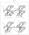
- 4A to 4C are perspective views showing a process of assembling a continuous coil to a stator core according to an embodiment of the present invention.
- 1 is a schematic diagram for explaining features of a continuous coil according to one embodiment of the present invention.
- FIG. FIG. 2 is a perspective view of the continuous coil of FIG.
- FIG. 13 is a perspective view showing a modified example of the continuous coil according to one embodiment of the present invention.
- FIG. 2 is a schematic diagram showing a heat dissipation path of a continuous coil according to one embodiment of the present invention.
- FIG. 11 is a diagram showing the relationship between the number of wire divisions of a coil and AC copper loss.
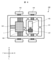
- 1 is a diagram showing the configuration of an xEV that employs a rotating electric machine according to an embodiment of the present invention.
- 1 is an exploded perspective view of a rotating electric machine according to an embodiment of the present invention;
- FIG. 2 is a schematic diagram illustrating heat generation in a rotating electric machine.
- 11 is a cross-sectional view of a stator core to which an edgewise coil, which is a comparative example of the present invention, is assembled, as viewed from the axial direction of a rotating electric machine.
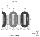
- FIG. 12 is a schematic diagram showing the magnetization state of teeth by the edgewise coil of FIG. 11.
- FIG. 9 is an exploded view of a rotating electric machine 1 according to one embodiment of the present invention.
- the rotating electric machine 1 comprises, as its main components, a stator 2, a rotor 3, an end bracket 4, and a power conversion device 5.
- the stator 2 has a stator core 21, and the rotor 3 has a rotor core 31.
- the rotor core 31 is arranged on the inner periphery side of the stator core 21 so that its outer periphery faces the inner periphery of the stator core 21.
- the stator 2 and the rotor 3 may be arranged so that the inner periphery of the rotor core 31 faces the outer periphery of the stator core 21.
- the power conversion device 5 performs switching operations to convert DC power supplied from a battery (not shown) into three-phase AC power.
- This three-phase AC power is supplied to a stator winding (not shown) of the stator 2, which generates a rotating magnetic field in the stator 2.
- the rotating magnetic field generated in the stator 2 drives the rotor 3 to rotate.
- the rotor 3 is provided with a rotating shaft.
- the dashed line 1a in Figure 9 represents the axis of the rotating shaft and its extension line.
- the direction along the axis of the rotating shaft is referred to as the "axial direction”
- the radial direction of the stator 2 or rotor 3 is referred to as the "radial direction.”
- FIG. 10 is a schematic diagram for explaining heat generation in the rotating electric machine 1'.
- the rotating electric machine 1' includes a stator core 21 and a rotor core 31.
- a gap 6 is formed between the mutually opposing surfaces of the stator core 21 and the rotor core 31.
- the stator core 21 includes teeth 21a-1, 21a-2 protruding radially inward, and a slot 21b formed between adjacent teeth 21a-1 and 21a-2.
- the rotating electric machine 1' and the rotating electric machine 1 of the present invention differ in the way in which the stator winding 10' (see FIG. 11) provided on the stator core 21 is wound.
- the stator winding 10' (coil 11') is composed of an edgewise wound coil (edgewise coil), which is a form of concentrated winding.
- Fig. 11 is a cross-sectional view of a stator core 21 to which an edgewise coil 10', which is a comparative example to the present invention, is assembled, as viewed from the axial direction of the rotating electric machine 1'.
- the stator winding 10' wound around the stator core 21 is formed by connecting a plurality of coils 11' wound around the teeth 21a-1.
- the coils 11' include two coils 11a', 11b' and a crossover wire 11c' that connects the two coils 11a', 11b'.
- the two coils 11a', 11b' and the crossover wire 11c' are formed as an integrated coil component using a continuous wire.
- the stator core 21 has the first teeth 21a-1 around which the coils 11' are wound, and the second teeth 21a-2 around which the coils 11' are not wound.
- the coils 11' wound around the first teeth 21a-1 are formed as edgewise coils in which the short side of the rectangular wire is wound on the inner diameter side of the coil, and the coils 11' are stacked radially and wound around the first teeth 21a-1.
- winding does not necessarily mean the action of winding a coil around a tooth, but rather the state in which the coil is arranged so as to go around the tooth. The same applies below.
- one coil 11a' is wound around the first tooth 21a-1 on the left side of the figure, and one coil 11b' is wound around the first tooth 21a-1 on the right side of the figure.
- the winding direction of coil 11a' is the same as that of coil 11b'.
- Coil 11a' has a first coil 11a-1' wound around the outermost side (rearmost side) of slot 21b, and a second coil 11a-2' wound around the innermost side of slot 21b (the tip end side of tooth 21a-1).
- Coil 11b' has a first coil 11b-1' wound around the outermost side (rearmost side) of slot 21b, and a second coil 11b-2' wound around the innermost side of slot 21b (the tip end side of tooth 21a-1).
- the coil 11a' wound around the first tooth 21a-1 on the left side and the coil 11b' wound around the first tooth 21a-1 on the right side are connected by a jumper wire 11c'.
- One end of the jumper wire 11c' is connected to the second coil 11a-2' arranged on the innermost side of the slot 21b in the coil 11a', and the other end of the jumper wire 11c' is connected to the first coil 11b-1' arranged on the outermost side of the slot in the coil 11b'.
- the jumper wire 11c' connects the second coil 11a-2' arranged on the innermost side of the slot 21b in the coil 11a' and the first coil 11b-1' arranged on the outermost side of the slot 21b in the coil 11b'.
- the jumper wire 11c' may be provided to connect the first coil 11a-1' in the coil 11a' and the second coil 11b-2' in the coil 11b'.
- FIG. 12 is a schematic diagram showing the magnetization state of the teeth 21a-1 and 21a-2 by the edgewise coil 10' of FIG.
- the edgewise coils 11' By arranging the edgewise coils 11' on every other tooth 21a-1, the first tooth 21a-1 is magnetized to an S pole and the second tooth 21a-2 is magnetized to an N pole in Fig. 12.
- the multiple teeth 21a-1, 21a-2 arranged all around the stator core 21 are magnetized so that the N poles and the S poles are arranged alternately in the circumferential direction.
- Losses occurring in the coils of rotating electrical machines include DC copper loss and AC copper loss.
- AC copper loss is eddy current loss in the coil, and can be reduced by dividing the cross-sectional area of the coil into smaller parts.
- the coil cross section is divided into four parts in the radial direction, but is not divided in the circumferential direction, which limits the reduction of AC copper loss.
- the coil 11' also generates heat due to DC copper loss and AC copper loss.
- the coil 11a-2' arranged at the back of the slot 21b has a large heat dissipation area relative to the stator core 21, and can dissipate the generated heat to the stator core 21 well.
- the coil 11a-1' arranged on the gap 6 side has a small heat dissipation area relative to the stator core 21, making it difficult to dissipate the generated heat to the stator core 21.
- the coil 11a-1' arranged on the gap 6 side receives heat dissipated from the magnet 32 of the rotor 31, and the slot 21b becomes hot due to the heat dissipated from the coil 11' and the magnet 32, making it difficult to dissipate the generated heat to the stator core 21.
- the closer the coil 11' is to the gap 6 side relative to the coil 11a-2' arranged at the back of the slot 21b the higher the temperature of the coil 11' tends to be.
- the coil 11a-1' arranged on the outermost side of the slot 21b will be referred to as the first coil or the coil on the outermost side of the slot
- the coil 11a-2' arranged on the innermost side of the slot 21b (gap 6 side) will be referred to as the second coil, the coil on the innermost side of the slot, or the gap side coil.
- Fig. 1 is a plan view of a stator core 21 to which a continuous coil 11 according to an embodiment of the present invention is assembled, as viewed from the axial direction of a rotating electric machine 1.
- Fig. 2 is a perspective view showing a process of assembling the continuous coil 11 according to an embodiment of the present invention to the stator core 21.
- the rotating electric machine 1 includes a stator core 21 having a plurality of teeth 21a-1, 21a-2 and slots 21b formed between adjacent teeth 21a-1, 21a-2, and a coil 11 wound around the tooth 21a-1.
- the stator winding wound around the stator core 21 is formed by connecting multiple coils 11 wound around teeth 21a-1.
- the coils 11 include two coils 11a, 11b and a jumper wire 11c that connects the two coils 11a, 11b.
- the two coils 11a, 11b and the jumper wire 11c are formed as an integrated coil component using a continuous material (strand wire).
- coils 11a and 11b are composed of a continuous conductor without a connection that connects two strands.
- the welding process and the insulating coating application process can be eliminated.
- the assembly process of rotating electric machine 1 can be simplified.
- the reliability of the rotating electric machine can be improved.
- each of the two coils 11a and 11b will be referred to as a coil, and the coil 11 composed of the two coils 11a and 11b will be referred to as a continuous coil.
- One coil 11a of the continuous coil 11 comprises a first coil 11a-1 arranged on the outermost side (innermost side) of the slot 21b, and a second coil 11a-2 arranged on the innermost side (gap side) of the slot 21b.
- the other coil 11b of the continuous coil 11 comprises a first coil 11b-1 arranged on the outermost side (innermost side) of the slot 21b, and a second coil 11b-2 arranged on the innermost side (gap side) of the slot 21b.
- the coils 11a-1, 11b-1 arranged on the outermost side of the slot 21b will be referred to as the first coil or the outermost slot coil
- the coils 11a-2, 11b-2 arranged on the innermost side of the slot 21b (gap 6 side) will be referred to as the second coil, the innermost slot coil, or the gap coil.
- one or more intermediate coils may be provided between the first coils 11a-1, 11b-1 and the second coils 11a-2, 11b-2.
- the jumper wire 11c connects the first coil 11a-1 wound around a given tooth 21a-1 to the second coil 11b-2 wound around another tooth 21a-1.
- the jumper wire 11c connects the first coil 11a-1 and the second coil 11b-2 arranged in adjacent slots 21b-1 and 21b-2, respectively.
- the jumper wire 11c may connect the second coil 11a-2 and the first coil 11b-1 arranged in adjacent slots 21b-1 and 21b-2, respectively.
- the continuous coil 11 is disposed on every other tooth 21a-1. Therefore, the stator core 21 has first teeth 21a-1 around which the continuous coil 11 is wound, and second teeth 21a-2 around which the continuous coil 11 is not wound.
- the jumper wires to adjacent coils are short, making it difficult to compression mold the straight sections (corresponding to 11a-6 and 11b-6 in Figures 4 and 5) of the two continuously wound coils (coils corresponding to coils 11a and 11b in this embodiment) using a mold.
- the length of the jumper wire 11c of the continuous coil 11 is the width of the teeth, so it is possible to set coils 11a and 11b in a mold and compression mold the straight sections 11a-6 and 11b-6 (see Figures 4 and 5).
- the coils 11a and 11b of this embodiment are inserted into the inside of the slot 21b with the straight sections 11a-6 and 11b-6 that are inserted into the inside of the slot 21b being compression molded to conform to the shape of the teeth 21a-1.
- the continuous coil 11 of this embodiment fits well into the slot 21b, improving the space factor.
- the teeth 21a-1 on which the coils 11a and 11b are provided have both side surfaces Sa and Sb extending in parallel from the outer periphery toward the inner periphery of the stator core 21.
- the teeth 21a-1 on which the coils 11a and 11b are provided are parallel teeth.
- teeth 21a-2 are formed so that their width increases from the inner periphery side to the outer periphery side of the stator core 21. For this reason, both side surfaces Sc, Sd of teeth 21a-2 are not parallel. Teeth 21a-2 are called trapezoidal teeth.
- the continuous coil 11 is made by inserting pre-wound coils 11a, 11b into teeth 21a-1. If coils 11a, 11b are inserted into trapezoidal teeth, gaps will form between adjacent teeth and coils 11a, 11b, resulting in a poor space factor.
- the stator core 21 has parallel teeth for teeth 21a-1, which improves the space factor.
- FIG. 3 is a schematic diagram for explaining the characteristics of the continuous coil 11 according to one embodiment of the present invention. The following description will be given with reference to Fig. 3(a).
- the continuous coil 11 is composed of alpha winding coils 11a and 11b, which are one form of concentrated winding.
- the coils 11a and 11b of the continuous coil 11 are each composed of an alpha winding coil.
- the wire is wound so as to overlap in the circumferential direction of the stator core 21.
- the coil 11a has a first coil 11a-1 and a second coil 11a-2.
- the first coil 11a-1 is wound so that the wire overlaps in the circumferential direction of the stator core 21.
- the second coil 11a-2 is wound so that the wire overlaps in the circumferential direction of the stator core 21.
- the first coil 11a-1 and the second coil 11a-2 are connected at the connection part 11a-5.
- one end 11a-3 is drawn out from the outermost wire of the first coil 11a-1
- the other end 11a-4 is drawn out from the outermost wire of the second coil 11a-2.
- the coil 11b has a first coil 11b-1 and a second coil 11b-2.
- the first coil 11b-1 is wound so that the wire overlaps in the circumferential direction of the stator core 21.
- the second coil 11b-2 is wound so that the wire overlaps in the circumferential direction of the stator core 21.
- the first coil 11b-1 and the second coil 11b-2 are connected at the connection part 11b-5.
- one end 11b-3 is drawn out from the outermost wire of the second coil 11b-2
- the other end 11b-4 is drawn out from the outermost wire of the first coil 11b-1.
- One end of the continuous coil 11 is composed of one end 11a-3 of coil 11a, and the other end of the continuous coil 11 is composed of one end 11b-3 of coil 11b.
- One end 11a-3 of the continuous coil 11 is drawn from either the coil on the outermost side of the slot or the coil on the innermost side of the slot (gap side coil), and the other end 11b-3 of the continuous coil 11 is drawn from the other coil on the outermost side of the slot or the coil on the innermost side of the slot (gap side coil).
- one end 11a-3 of the continuous coil 11 is drawn from the first coil 11a-1 of coil 11a
- the other end 11b-3 of the continuous coil 11 is drawn from the second coil 11b-2 of coil 11b.
- coil 11a the first coil 11a-1 and the second coil 11a-2 are wound clockwise when viewed from above in FIG. 3.
- the first coil 11b-1 and the second coil 11b-2 are also wound clockwise when viewed from above in FIG. 3.
- the first coil 11a-1 and the second coil 11a-2 of coil 11a and the first coil 11b-1 and the second coil 11b-2 of coil 11b are all wound in the same direction. In this way, in the alpha winding continuous coil 11, the coils are wound so that current flows in the same rotational direction in coils 11a and 11b.
- the alpha winding coil is wound separately on the first coil 11a-1, 11b-1 side and the second coil 11a-2, 11b-2 side.
- the first coil 11a-1, 11b-1 and the second coil 11a-2, 11b-2 may each be wound in multiple stages in the radial direction. In this case, the number of stages in each coil 11a-1, 11b-1, 11a-2, 11b-2 may be different.
- the minimum number of stages in each coil 11a-1, 11b-1, 11a-2, 11b-2 is one stage in the radial direction, for a total of two stages.
- One end 11c-1 of the jumper wire 11c is connected to the end 11a-4 of the coil 11a.
- One end 11c-1 of the jumper wire 11c is pulled out continuously from the end 11a-4 of the coil 11a.
- one end 11c-1 of the jumper wire 11c is bent in the opposite direction to the winding direction of the coil 11a and pulled out from the end 11a-4 of the coil 11a.
- the other end 11c-2 of the jumper wire 11c is connected to the end 11b-4 of the coil 11b.
- the other end 11c-2 of the jumper wire 11c is pulled out continuously from the end 11b-4 of the coil 11b.
- the other end 11c-2 of the jumper wire 11c is bent in the opposite direction to the winding direction of the coil 11b and pulled out from the end 11b-4 of the coil 11b.
- the jumper wire 11c is formed by bending the start point 11c-1 and the end point 11c-2 in the opposite direction to the winding direction of the coils 11a and 11b.
- the jumper wire 11c is formed by extending the wire from the winding direction in the continuous alpha-wound coil 11, the number of turns of the second coils 11a-2 and 11b-2 to which the jumper wire 11c is connected will be reduced by 0.5 turns. The effect is small when the number of turns is large, but is large in the case of a motor with a small number of turns such as an EV drive motor.
- the jumper wire structure of this embodiment With the jumper wire structure of this embodiment, the reduction in the number of turns is suppressed in the second coil 11a-2 of the coil 11a and the first coil 11b-1 of the coil 11b to which the jumper wire 11c is connected, making it possible to completely wind the coils. As a result, the coil space factor can be improved.
- FIG. 4 is a perspective view of the continuous coil 11 of FIG.
- the coils 11a and 11b are composed of a plurality of coated conductors (parallel magnet wires).
- the AC copper loss can be reduced.
- the loss of the coils 11a and 11b can be reduced, and the heat generation of the coils 11a and 11b can be suppressed.
- the strands of the continuous coil 11 in this embodiment are composed of five coated conductors.
- the wires of the coils 11a and 11b are made up of multiple round wires. Because the wires of the coils 11a and 11b are made up of multiple round wires, a conventional round wire winding machine can be used and the winding work can be performed relatively easily.
- coils 11a and 11b may be made of the rectangular wire described in FIG. 11.
- FIG. 5 is a perspective view showing a modified example of the continuous coil 11 according to an embodiment of the present invention.
- the continuous coil 11 of FIG. 4 an example is shown in which the crossover wire 11c is not twisted.
- FIG. 5 shows an example in which a twist is added to the crossover wire 11c.
- the jumper wire in Figure 5 is twisted 180 degrees to connect the first coil 11a-1 of coil 11a wound around a specified tooth 21a-1a (see Figure 1) and the second coil 11b-2 of coil 11b wound around the other tooth 21a-1b (see Figure 1).
- the wires of jumper wire 11c By twisting the wires of jumper wire 11c by 180 degrees, the positions of the coated conductors located on the outer periphery and the inner periphery of coils 11a, 11b are swapped in the multiple coated conductors, thereby equalizing the length of each coated conductor. This makes it possible to equalize the conductor resistance of the multiple coated conductors that make up jumper wire 11c and level out the current sharing of each coated conductor.
- the helical structure of the jumper wire 11c makes it easy to expand and contract, and when inserting the coils 11a and 11b into the stator core 21, the jumper wire 11c can be deformed in the circumferential direction of the stator core 21, making it possible to smoothly insert the coils 11a and 11b into the stator core 21.
- FIG. 6 is a schematic diagram showing the heat dissipation path of the continuous coil 11 according to one embodiment of the present invention.
- the first coil 11a-1 of the coil 11a and the first coil 11b-1 of the coil 11b have a large opposing or contact area with the stator core 21, and high heat dissipation performance to the stator core 21 can be ensured.
- the second coil 11a-2 of coil 11a and the second coil 11b-2 of coil 11b have a small opposing or contact area with the stator core 21, and because the temperature of the teeth 21a-1, 11a-2, which serve as the heat dissipation path, rises, it is difficult to ensure high heat dissipation performance to the stator core 21. Therefore, the number of circumferential divisions of the second coils 11a-2, 11b-2 is increased to reduce AC copper loss due to magnetic flux.
- the second coils 11a-2, 11b-2 also reach the highest temperature due to AC copper loss. Therefore, the second coils 11a-2, 11b-2 dissipate heat through the crossover wire 11c to the first coils (coils on the outermost slot side) 11a-1, 11b-1, which have low loss and good heat dissipation properties, thereby leveling out the temperature of the entire continuous coil 11 (reducing the maximum temperature).
- AC copper loss can also be reduced by dividing it in the radial direction, but dividing it in the circumferential direction has a greater effect than dividing it in the radial direction.
- the number of radial divisions in coil 11' in FIG. 11 is greater than the number of radial divisions in the continuous coil 11 of this embodiment, and the effect of reducing AC copper loss due to the number of radial divisions is greater in coil 11' than in the continuous coil 11 of this embodiment.
- the effect of reducing AC copper loss due to the number of circumferential divisions is greater than the effect of reducing AC copper loss due to the number of radial divisions, so overall the continuous coil 11 of this embodiment has a greater effect of reducing AC copper loss than the coil 11' in FIG. 11.
- the rotating electric machine 1 of this embodiment can improve the output density by reducing losses and improving heat dissipation in the continuous coil 11. As a result, the rotating electric machine 1 can be made smaller and lighter, and its power consumption can be improved.
- FIG. 7 is a diagram showing the relationship between the number of wire divisions of the coils 11a and 11b and AC copper loss.
- AC copper loss is the eddy current loss of the coils 11a and 11b, and it is known that the eddy current loss is proportional to the square of the plate thickness. If the eddy current loss without wire division is 1 pu, the relationship between the number of divisions and the eddy current loss is as shown in Figure 7.
- the number of turns in coil 11 is set to 4 to 12 turns. In other words, the number of turns in coils 11a and 11b is 4 to 12 turns. As a result, the rotating electric machine 1 of this embodiment can achieve a significant reduction in AC copper loss.
- the rotating electric machine 1 of the present embodiment described above has the following configuration.
- a rotating electric machine 1 including a stator core 21 having a plurality of teeth 21a-1, 21a-2 and slots 21b formed between adjacent teeth 21a-1, 21a-2, and coils 11a, 11b wound around the tooth 21a-1,
- the coils 11a and 11b are First coils 11a-1, 11b-1 are arranged on the outermost side of slots 21b and are provided so as to overlap in the circumferential direction of stator core 21; Second coils 11a-2, 11b-2 are arranged on the innermost side of the slot 21b and are provided so as to overlap each other in the circumferential direction; a jumper wire 11c that connects a first coil 11a-1 wound around a predetermined tooth 21a-1a and a second coil 11b-2 wound around another tooth 21a-1b; The crossover wire 11c connects the first coil 11a-1 and the second coil 11b-2 arranged in the adjacent slots 21b-1 and 21b-2, respectively.
- the rotating electrical machine 1 of this embodiment provides the following advantageous effects.
- the second coil 11a-2 of the coil 11a and the second coil 11b-2 of the coil 11b can reduce AC copper loss due to magnetic flux by increasing the number of circumferential divisions.
- the rotating electric machine 1 of this embodiment can improve the output density by reducing loss and improving heat dissipation in the coil 11.
- the rotating electric machine 1 can be made smaller and lighter, and the electric power consumption can be improved.
- FIG. 8 is a diagram showing the configuration of an xEV 100 that employs the rotating electric machine 1 according to an embodiment of the present invention.
- a rotating electric machine 1 serving as a drive motor is fixedly supported on a bogie 101 by a support member 102.
- a rotor of the rotating electric machine 1 is coupled to an axle 106, and the rotating electric machine 1 drives wheels 103 via the axle 106.
- the vehicle 100 includes the rotating electric machine 1, a battery 105, and a power conversion device 107 that converts DC power of the battery 105 into AC power and supplies the AC power to the rotating electric machine 1.
- the xEV of this embodiment by being equipped with the rotating electric machine 1 of this embodiment, it is possible to improve the space factor of the coil 11 in the slot, reduce losses, and realize a simple coil heat dissipation structure, thereby achieving a high output density of the drive motor. This not only provides high torque, but also provides an xEV with excellent cost performance.
- the present invention is not limited to the above-described embodiments, but includes various modified examples.
- the above-described embodiments have been described in detail to clearly explain the present invention, and the present invention is not necessarily limited to those including all of the configurations.
Landscapes
- Engineering & Computer Science (AREA)
- Power Engineering (AREA)
- Windings For Motors And Generators (AREA)
Priority Applications (1)
| Application Number | Priority Date | Filing Date | Title |
|---|---|---|---|
| JP2025509818A JPWO2024202493A1 (https=) | 2023-03-27 | 2024-01-29 |
Applications Claiming Priority (2)
| Application Number | Priority Date | Filing Date | Title |
|---|---|---|---|
| JP2023-049845 | 2023-03-27 | ||
| JP2023049845 | 2023-03-27 |
Publications (1)
| Publication Number | Publication Date |
|---|---|
| WO2024202493A1 true WO2024202493A1 (ja) | 2024-10-03 |
Family
ID=92903984
Family Applications (1)
| Application Number | Title | Priority Date | Filing Date |
|---|---|---|---|
| PCT/JP2024/002687 Ceased WO2024202493A1 (ja) | 2023-03-27 | 2024-01-29 | 回転電機 |
Country Status (2)
| Country | Link |
|---|---|
| JP (1) | JPWO2024202493A1 (https=) |
| WO (1) | WO2024202493A1 (https=) |
Citations (4)
| Publication number | Priority date | Publication date | Assignee | Title |
|---|---|---|---|---|
| JP2008109829A (ja) * | 2006-10-27 | 2008-05-08 | Toyota Motor Corp | 回転電機の固定子構造及びその製造方法 |
| WO2011001736A1 (ja) * | 2009-06-29 | 2011-01-06 | トヨタ自動車株式会社 | 多層巻きコイル、ステータ、及びその製造方法 |
| JP2022114571A (ja) * | 2021-01-27 | 2022-08-08 | ダイキン工業株式会社 | モータ、圧縮機、及び冷凍装置 |
| JP2022151931A (ja) * | 2021-03-29 | 2022-10-12 | 株式会社日立製作所 | 回転電機の固定子、回転電機、電気駆動システム、及び電動ホイール |
-
2024
- 2024-01-29 JP JP2025509818A patent/JPWO2024202493A1/ja active Pending
- 2024-01-29 WO PCT/JP2024/002687 patent/WO2024202493A1/ja not_active Ceased
Patent Citations (4)
| Publication number | Priority date | Publication date | Assignee | Title |
|---|---|---|---|---|
| JP2008109829A (ja) * | 2006-10-27 | 2008-05-08 | Toyota Motor Corp | 回転電機の固定子構造及びその製造方法 |
| WO2011001736A1 (ja) * | 2009-06-29 | 2011-01-06 | トヨタ自動車株式会社 | 多層巻きコイル、ステータ、及びその製造方法 |
| JP2022114571A (ja) * | 2021-01-27 | 2022-08-08 | ダイキン工業株式会社 | モータ、圧縮機、及び冷凍装置 |
| JP2022151931A (ja) * | 2021-03-29 | 2022-10-12 | 株式会社日立製作所 | 回転電機の固定子、回転電機、電気駆動システム、及び電動ホイール |
Also Published As
| Publication number | Publication date |
|---|---|
| JPWO2024202493A1 (https=) | 2024-10-03 |
Similar Documents
| Publication | Publication Date | Title |
|---|---|---|
| JP5664927B2 (ja) | 導体線及び回転電機 | |
| JP4158024B2 (ja) | 誘導電動機 | |
| CN103404003B (zh) | 旋转电机用定子 | |
| CN104584391B (zh) | 旋转电机及其制造方法 | |
| JP5924710B2 (ja) | 回転電機 | |
| KR20070021315A (ko) | 미니 캡을 갖는 기계-전기 변환기 고정자 코어 | |
| JP5195804B2 (ja) | 回転電機の回転子 | |
| WO2018180721A1 (ja) | 電動モータ | |
| JP4624421B2 (ja) | 平角線巻線を有する永久磁石同期機 | |
| JP2013158213A (ja) | 回転電機 | |
| JP2009232607A (ja) | 回転電機の固定子用巻線および回転電機 | |
| JP2010124636A (ja) | コイルユニットおよびステータ | |
| CN103035463B (zh) | 具有带轭铁绕组的定子的旋转阳极的驱动装置 | |
| JP6598736B2 (ja) | 回転電機の固定子 | |
| JP2012095488A (ja) | 回転電機用ロータ、およびこれを用いた回転電機 | |
| CN214412445U (zh) | 一种电机定子绕组、电机定子及电机 | |
| CN214543852U (zh) | 一种电机定子绕组、电机定子及电机 | |
| JP5072502B2 (ja) | 回転電動機 | |
| JP2004208464A (ja) | 電動機の巻線構造 | |
| WO2024202493A1 (ja) | 回転電機 | |
| US20230396113A1 (en) | Stator for a rotating electrical machine | |
| JP6394542B2 (ja) | 回転電機ステータ | |
| JP2013243904A (ja) | 回転電機 | |
| JP6968215B2 (ja) | 回転電機 | |
| JP2007336725A (ja) | 回転電機の固定子 |
Legal Events
| Date | Code | Title | Description |
|---|---|---|---|
| 121 | Ep: the epo has been informed by wipo that ep was designated in this application |
Ref document number: 24778639 Country of ref document: EP Kind code of ref document: A1 |
|
| ENP | Entry into the national phase |
Ref document number: 2025509818 Country of ref document: JP Kind code of ref document: A |
|
| WWE | Wipo information: entry into national phase |
Ref document number: 2025509818 Country of ref document: JP |
|
| NENP | Non-entry into the national phase |
Ref country code: DE |
|
| 122 | Ep: pct application non-entry in european phase |
Ref document number: 24778639 Country of ref document: EP Kind code of ref document: A1 |