WO2024202342A1 - 切削工具及び切削加工物の製造方法 - Google Patents
切削工具及び切削加工物の製造方法 Download PDFInfo
- Publication number
- WO2024202342A1 WO2024202342A1 PCT/JP2023/046571 JP2023046571W WO2024202342A1 WO 2024202342 A1 WO2024202342 A1 WO 2024202342A1 JP 2023046571 W JP2023046571 W JP 2023046571W WO 2024202342 A1 WO2024202342 A1 WO 2024202342A1
- Authority
- WO
- WIPO (PCT)
- Prior art keywords
- screw hole
- cutting tool
- cutting
- screw
- holder
- Prior art date
- Legal status (The legal status is an assumption and is not a legal conclusion. Google has not performed a legal analysis and makes no representation as to the accuracy of the status listed.)
- Ceased
Links
Images


Classifications
-
- B—PERFORMING OPERATIONS; TRANSPORTING
- B23—MACHINE TOOLS; METAL-WORKING NOT OTHERWISE PROVIDED FOR
- B23C—MILLING
- B23C5/00—Milling-cutters
- B23C5/02—Milling-cutters characterised by the shape of the cutter
- B23C5/10—Shank-type cutters, i.e. with an integral shaft
-
- B—PERFORMING OPERATIONS; TRANSPORTING
- B23—MACHINE TOOLS; METAL-WORKING NOT OTHERWISE PROVIDED FOR
- B23C—MILLING
- B23C9/00—Details or accessories so far as specially adapted to milling machines or cutter
-
- B—PERFORMING OPERATIONS; TRANSPORTING
- B23—MACHINE TOOLS; METAL-WORKING NOT OTHERWISE PROVIDED FOR
- B23Q—DETAILS, COMPONENTS, OR ACCESSORIES FOR MACHINE TOOLS, e.g. ARRANGEMENTS FOR COPYING OR CONTROLLING; MACHINE TOOLS IN GENERAL CHARACTERISED BY THE CONSTRUCTION OF PARTICULAR DETAILS OR COMPONENTS; COMBINATIONS OR ASSOCIATIONS OF METAL-WORKING MACHINES, NOT DIRECTED TO A PARTICULAR RESULT
- B23Q11/00—Accessories fitted to machine tools for keeping tools or parts of the machine in good working condition or for cooling work; Safety devices specially combined with or arranged in, or specially adapted for use in connection with, machine tools
Definitions
- the present disclosure relates to a cutting tool and a method for manufacturing a machined product.
- cutting tools include rotary tools and turning tools.
- rotary tools include milling tools.
- Turning tools are used for turning processes such as face milling and end milling.
- turning tools include external diameter machining tools, internal diameter machining tools, grooving tools, and cut-off tools.
- Known cutting tools include the rotary tools described in Patent Documents 1 and 2.
- the rotary tools described in Patent Documents 1 and 2 each have a cutting insert (described as a throw-away tip in Patent Documents 1 and 2), a holder, and a clamp screw.
- the cutting insert is fixed to the holder by the clamp screw. When the cutting insert wears out, it is possible to replace the cutting insert by removing the clamp screw.
- the cutting tool disclosed herein includes a holder that extends from the tip to the rear end and has a pocket located on the tip side, a cutting insert located in the pocket, and a screw that fixes the cutting insert to the holder, and the holder has a first screw hole that opens into the pocket and into which the screw is attached, and a second screw hole that is located away from the pocket and into which the screw can be inserted.
- the method for manufacturing a machined product according to the present disclosure includes the steps of rotating a cutting tool according to the present disclosure, bringing the cutting tool into contact with a workpiece, and removing the cutting tool from the workpiece.
- the method for manufacturing a machined product according to the present disclosure includes the steps of rotating a workpiece, bringing a cutting tool according to the present disclosure into contact with the rotating workpiece, and removing the cutting tool from the workpiece.
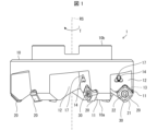
- FIG. 1 is a schematic side view of a cutting tool according to an embodiment of the present disclosure.
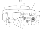
- FIG. 2 is a schematic perspective view showing a state in which only one cutting insert is attached to the cutting tool shown in FIG. 1 .
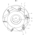
- 3 is a schematic perspective view of the cutting tool shown in FIG. 1 with one cutting insert attached thereto, as viewed from an angle different from that shown in FIG. 2 .
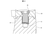
- 4 is a cross-sectional view taken along line IV-IV in FIG. 2.
- 3 is a cross-sectional view taken along line VV in FIG. 2.
- FIG. 2 is a schematic exploded perspective view of a mounting portion of a cutting insert in the cutting tool shown in FIG. 1 .
- FIG. 1A to 1C are schematic diagrams illustrating a manufacturing method of a machined product according to an embodiment of the present disclosure.
- 1A to 1C are schematic diagrams illustrating a manufacturing method of a machined product according to an embodiment of the present disclosure.
- 1A to 1C are schematic diagrams illustrating a manufacturing method of a machined product according to an embodiment of the present disclosure.
- Cutting tools are used while attached to machine tools such as NC (Numerical Control) lathes or machining centers.
- machine tools such as NC (Numerical Control) lathes or machining centers.
- the clamp screw is placed outside the machine tool. In that case, the clamp screw necessarily has to move a long distance, and there is a risk that the clamp screw will fall off during the movement.
- each of the drawings referred to below shows a simplified view of only the components necessary for explaining the embodiment. Therefore, the cutting tool according to the embodiment of the present disclosure may include any components not shown in each of the drawings referred to. Furthermore, the dimensions of the components in each drawing do not faithfully represent the actual dimensions of the components and the dimensional ratios of each member, etc.
- FIG. 1 is a schematic side view of the cutting tool 1 according to the embodiment of the present disclosure.
- FIG. 2 is a schematic perspective view showing a state in which only one cutting insert is attached to the cutting tool 1 shown in FIG. 1.
- FIG. 2 is a view from an angle in which the cutting insert is in front.
- FIG. 3 is a schematic perspective view showing a state in which the cutting tool shown in FIG. 1 is attached to one cutting insert, as viewed from an angle different from that of FIG. 2.
- FIG. 4 is a cross-sectional view taken along line IV-IV in FIG. 2.
- FIG. 5 is a cross-sectional view taken along line V-V in FIG. 2.
- FIG. 6 is a schematic exploded perspective view of a mounting portion of the cutting insert in the cutting tool 1 shown in FIG. 1.
- FIG. 7 is a schematic perspective view showing a state in which a fixing screw is attached to the second screw hole of the cutting tool 1 shown in FIG. 1.
- the cutting tool 1 is a tool that can rotate around a rotation axis RS.
- the cutting tool 1 is used for cutting a workpiece W (see Figure 8) described below.
- the cutting tool 1 may have a holder 10 that is attached to the spindle of a processing machine such as a milling machine.
- the holder 10 may extend from a first end (tip) 10a to a second end (rear end) 10b along the rotation axis RS.
- the holder 10 may be cylindrical as in the example, or may be prismatic. Examples of materials for the holder 10 include metals such as stainless steel, carbon steel, cast iron, and aluminum alloys.
- the holder 10 may have a chip pocket (pocket) 11 located on the side of the first end 10a.
- the chip pocket 11 may be a recess for mounting the cutting insert 20.
- the chip pocket 11 may be located in multiple locations on the outer circumferential surface of the holder 10.
- the holder 10 may also have a chip pocket 12.
- the chip pocket 12 may be a recess that temporarily receives chips generated when the cutting insert 20 cuts the workpiece W (see FIG. 8 ), making it easier for the chips to flow in the discharge direction.
- a plurality of chip pockets 12 may be located on the outer peripheral surface of the holder 10.
- the chip pocket 11 described above may be located in the chip pocket 12.
- the multiple chip pockets 11 and multiple chip pockets 12 may be spaced apart in the circumferential direction on the outer circumferential surface of the holder 10. In this case, they may be spaced apart in the circumferential direction evenly or unevenly.
- the number of chip pockets 11 and chip pockets 12 for a holder 10 may be one each.
- the cutting tool 1 may have a cutting insert 20 located in a chip pocket 11 of the holder 10 and a fixing screw 30 that fixes the cutting insert 20 to the holder.
- the cutting insert 20 may be located only in one or more selected chip pockets 11 in the holder 10. As shown in the example in FIG. 6, the cutting insert 20 may have a cutting edge 21 and a mounting hole 22 penetrating in the thickness direction.
- An octagonal plate shape is shown as an example of the cutting insert 20, but it may be a polygonal plate shape other than an octagonal plate shape, such as a triangular plate shape or a square plate shape.
- the cutting insert 20 may be rotationally symmetrical at a certain angle around the center of the mounting hole 22.
- the cutting insert 20 may be inverted symmetrical on the front and back.
- the cutting insert 20 may be a double-sided insert with both upper and lower cutting edges.
- the holder 10 may further have a first screw hole 13 and a second screw hole 14.
- the first screw hole 13 may open into the chip pocket 11 and may be configured to receive a fixing screw 30.
- the cutting insert 20 may be fixed to the holder 10 by a fixing screw (screw) 30 inserted through the mounting hole 22 and screwed into the first screw hole 13.
- the cutting insert 20 may be configured to be removed from the holder 10 by releasing the screw engagement between the fixing screw 30 and the first screw hole 13.
- the second screw hole 14 may be located away from the chip pocket 11 and may be configured to allow attachment of a fixing screw 30, as in the example shown in FIG. 7.
- the second screw hole 14 may have the same thread as the first screw hole 13 formed on the inner surface of a portion having the same hole diameter as the first screw hole 13, as in the example shown in FIG. 5.
- the fixing screw 30 is temporarily removed from the first screw hole 13.
- the fixing screw 30 removed from the first screw hole 13 can be temporarily attached to the second screw hole 14 as shown in the example in FIG. 7.
- the worker can move more compactly during replacement work compared to when the removed fixing screw 30 is taken outside the machine tool and temporarily placed there, making the replacement work easier. Furthermore, the distance the fixing screw 30 needs to be moved is significantly shorter, reducing the occurrence of problems such as the fixing screw 30 falling off during movement. In other words, the above configuration makes it possible to easily and stably replace the cutting insert 20. This also makes it possible to automate the replacement of the cutting insert 20 using devices such as a robot hand.
- the second screw hole 14 may be adjacent to the chip pocket 11.
- the second screw hole 14 is positioned close to the chip pocket 11, and the distance that the fixing screw 30 removed from the first screw hole 13 must be moved is further shortened. This makes the worker's movements more compact when replacing the cutting insert 20, making the replacement work easier. This further reduces the occurrence of problems such as the fixing screw 30 falling off during movement.
- the central axis C2 of the second screw hole 14 may be parallel to the central axis C1 of the first screw hole 13.
- the fixing screw 30 can be attached and removed in the same direction in the first screw hole 13 and the second screw hole 14.
- the task of attaching and removing the fixing screw 30 in the second screw hole 14 is simplified. This has the advantage that when replacing the cutting insert 20 is automated using a device such as a robot hand, the movement of the device can be simplified, and the device can be prevented from becoming complicated.
- the second screw hole 14 may be configured to be located closer to the second end 10b of the holder 10 than the first screw hole 13.
- This configuration reduces the risk of chips generated during cutting entering the second screw hole 14. That is, during cutting, the cutting tool 1 is attached to the spindle of the processing machine so that the first end 10a of the holder 10 faces vertically downward (see FIG. 8). Therefore, the generated chips move vertically downward due to gravity. With the above configuration, the second screw hole 14 is more likely to be positioned vertically above the cutting edge of the cutting insert 20, making it difficult for chips to enter the second screw hole 14.
- the second screw hole 14 may be configured to be located closer to the second end 10b of the holder 10 than the cutting insert 20. In such a configuration, it becomes even more difficult for cutting chips to get into the second screw hole 14.
- the holder 10 extends along the rotation axis RS from the first end 10a, which is the tip, to the second end 10b, which is the rear end, and the second screw hole 14 may be located closer to the rotation axis RS than the first screw hole 13.
- This configuration also reduces the risk of chips generated during cutting entering the second screw hole 14.
- the cutting tool 1 is rotated around the rotation axis RS in the rotation direction T. Therefore, the generated chips move in a direction away from the rotation axis RS due to centrifugal force.
- the second screw hole 14 By positioning the second screw hole 14 closer to the rotation axis RS than the cutting insert 20, it becomes more difficult for chips to enter the second screw hole 14.
- the opening of the second screw hole 14 may be located further forward in the rotational direction of the rotation axis RS than the opening of the first screw hole 13.
- the generated chips move more in the direction opposite to the rotational direction T. Therefore, with this configuration, the risk of chips generated during cutting entering the second screw hole 14 can be further reduced.
- the holder 10 may further have a cavity 16 that penetrates the inside of the holder 10 and communicates with the second screw hole 14.
- the holder 10 may further have a cavity 16 that extends from the second end 10b side to the second screw hole 14.
- the cavity 16 may be connected to the side wall on the bottom side of the second screw hole 14 from the second end 10b side of the holder 10.
- This configuration makes it possible to flow a fluid, such as a liquid or gas, into the hollow portion 16. As a result, even if chips get into the second screw hole 14, the chips can be expelled by flowing a fluid into the hollow portion 16.
- a fluid such as a liquid or gas
- the hollow portion 16 may be connected to the coolant hole.
- the second screw hole 14 may have a space 17.
- the space 17 may be recessed so that the inner diameter is larger than the area of the second screw hole 14 where the threads are formed.
- the chips are more likely to be trapped in the space 17 and are less likely to get caught in the threads.
- a space 17 may be provided so that when the fixing screw 30 is attached to the second screw hole 14, a space is provided around the fixing screw 30.
- the space 17 may also be configured to allow the fluid 40 supplied from the hollow portion 16 to pass through. When the second screw hole 14 is configured in this way, chips remaining in the space 17 are more likely to be removed by the fluid 40.
- the space 17 becomes a flow path for the fluid 40 supplied from the cavity 16, and the fluid 40 is discharged from the opening of the space 17 while coming into contact with the periphery of the fixing screw 30.
- the second screw hole 14 may be configured to have a first hole portion 14a having the same hole diameter as the first screw hole 13, and a plurality of second hole portions 14b located around the first hole portion 14a and communicating with the first hole portion 14a.
- the plurality of second hole portions 14b are located on the opening side of the second screw hole 14, and form a space portion 17. In one example of the present disclosure, three second hole portions 14b are formed.
- connection between adjacent second hole portions 14b is the inner peripheral surface of the first hole portion 14a, and the same thread as the first screw hole 13 is formed at this connection portion.
- the second hole portion 14b may be formed deeper than the lower end of the fixing screw 30 attached to the second screw hole 14.
- Fig. 8 to Fig. 10 are schematic diagrams for explaining a method for manufacturing a machined product according to an embodiment of the present disclosure.
- Fig. 8 to Fig. 10 illustrate a cutting tool 1 according to an embodiment of the present disclosure.
- the manufacturing method of the machined product according to the embodiment of the present disclosure is a manufacturing method for manufacturing the machined product M by cutting the workpiece W using the cutting tool 1, and may include a first step, a second step, and a third step.
- the first step is a step of rotating the cutting tool 1.
- the second step is a step of bringing the rotating cutting tool 1 into contact with the workpiece W.
- the third step is a step of separating the cutting tool 1 from the workpiece W.
- Examples of the material of the workpiece W include aluminum alloy, stainless steel, carbon steel, alloy steel, cast iron, and non-ferrous metal.
- the cutting tool 1 is rotated in the rotation direction T while being moved in the direction of the arrow FD to approach the workpiece W. Then, the cutting insert 20 of the rotating cutting tool 1 is moved in the direction of the arrow FD while being brought into contact with the workpiece W. As a result, the cutting tool 1 cuts the workpiece W, and as shown in the example in Figure 10, a machined surface Wf is formed on the workpiece.
- the cutting tool 1 is further moved in the direction of the arrow FD to separate it from the workpiece W. This completes the cutting of the workpiece W, and a machined product M can be produced, which is the workpiece W that has been machined.
- the cutting insert 20 of the cutting tool 1 can be repeatedly brought into contact with different locations on the workpiece W while rotating the cutting tool 1.
- the cutting tool 1 allows the cutting insert 20 to be easily and stably replaced.
- the replacement of the cutting insert 20 can be automated using a device such as a robot hand. This improves productivity and reduces manufacturing costs.
- the manufacturing method of the machined product according to the present disclosure is a manufacturing method for manufacturing a machined product by cutting the workpiece using a cutting tool, and may include a step of rotating the workpiece, a step of bringing the cutting tool according to the present disclosure into contact with the rotating workpiece, and a step of moving the cutting tool according to the present disclosure away from the workpiece.
- a cutting tool 1 is exemplified, but as described above, examples of cutting tools include rotary tools and turning tools.
- Rotary tools include, for example, cutting tools (milling tools). Turning tools are used for turning processes such as face milling and end milling. Examples of turning tools include external diameter machining tools, internal diameter machining tools, grooving tools, and cut-off tools.
- Cutting tool 10 Holder 10b Rear end 11 Chip pocket (pocket) 12 chip pocket 13 first screw hole 14 second screw hole 14a first hole portion 14b second hole portion 16 cavity portion 20 cutting insert 22 mounting hole RS rotation axis Wf machining surface
Landscapes
- Engineering & Computer Science (AREA)
- Mechanical Engineering (AREA)
- Milling Processes (AREA)
Priority Applications (1)
| Application Number | Priority Date | Filing Date | Title |
|---|---|---|---|
| JP2025509752A JPWO2024202342A1 (https=) | 2023-03-30 | 2023-12-26 |
Applications Claiming Priority (2)
| Application Number | Priority Date | Filing Date | Title |
|---|---|---|---|
| JP2023056531 | 2023-03-30 | ||
| JP2023-056531 | 2023-03-30 |
Publications (1)
| Publication Number | Publication Date |
|---|---|
| WO2024202342A1 true WO2024202342A1 (ja) | 2024-10-03 |
Family
ID=92904728
Family Applications (1)
| Application Number | Title | Priority Date | Filing Date |
|---|---|---|---|
| PCT/JP2023/046571 Ceased WO2024202342A1 (ja) | 2023-03-30 | 2023-12-26 | 切削工具及び切削加工物の製造方法 |
Country Status (2)
| Country | Link |
|---|---|
| JP (1) | JPWO2024202342A1 (https=) |
| WO (1) | WO2024202342A1 (https=) |
Citations (5)
| Publication number | Priority date | Publication date | Assignee | Title |
|---|---|---|---|---|
| JP2001252802A (ja) * | 2000-03-09 | 2001-09-18 | Sumitomo Electric Ind Ltd | スローアウェイチップ保持具 |
| JP2004306245A (ja) * | 2003-03-26 | 2004-11-04 | Ngk Spark Plug Co Ltd | カッターボディおよび回転工具、並びに回転工具の組立方法 |
| JP2007260892A (ja) * | 2006-03-02 | 2007-10-11 | Mitsubishi Materials Corp | インサート着脱式切削工具 |
| JP2010234457A (ja) * | 2009-03-30 | 2010-10-21 | Mitsubishi Materials Corp | インサート着脱式切削工具 |
| WO2022118946A1 (ja) * | 2020-12-04 | 2022-06-09 | 京セラ株式会社 | 切削インサート、切削工具及び切削加工物の製造方法 |
-
2023
- 2023-12-26 JP JP2025509752A patent/JPWO2024202342A1/ja active Pending
- 2023-12-26 WO PCT/JP2023/046571 patent/WO2024202342A1/ja not_active Ceased
Patent Citations (5)
| Publication number | Priority date | Publication date | Assignee | Title |
|---|---|---|---|---|
| JP2001252802A (ja) * | 2000-03-09 | 2001-09-18 | Sumitomo Electric Ind Ltd | スローアウェイチップ保持具 |
| JP2004306245A (ja) * | 2003-03-26 | 2004-11-04 | Ngk Spark Plug Co Ltd | カッターボディおよび回転工具、並びに回転工具の組立方法 |
| JP2007260892A (ja) * | 2006-03-02 | 2007-10-11 | Mitsubishi Materials Corp | インサート着脱式切削工具 |
| JP2010234457A (ja) * | 2009-03-30 | 2010-10-21 | Mitsubishi Materials Corp | インサート着脱式切削工具 |
| WO2022118946A1 (ja) * | 2020-12-04 | 2022-06-09 | 京セラ株式会社 | 切削インサート、切削工具及び切削加工物の製造方法 |
Also Published As
| Publication number | Publication date |
|---|---|
| JPWO2024202342A1 (https=) | 2024-10-03 |
Similar Documents
| Publication | Publication Date | Title |
|---|---|---|
| US6901642B2 (en) | Cutting tool, insert holder and machining method | |
| US9770770B2 (en) | Rigid universal cartridge for holding system | |
| JP2013233648A (ja) | フライス加工工具 | |
| JP2003200310A (ja) | 工 具 | |
| US20100232890A1 (en) | Cutting tool including a cutting insert retaining and adjusting mechanism | |
| US9757835B2 (en) | Tool changer with cover means | |
| JP4816496B2 (ja) | 穴加工工具 | |
| TWI790373B (zh) | 車床 | |
| WO2022118492A1 (ja) | 加工機械 | |
| JP4816723B2 (ja) | インサート | |
| CN114555268B (zh) | 用于可转位转塔的刀夹以及切断和切槽刀具以及该刀夹以及切断和切槽刀具的加工方法 | |
| WO2024202342A1 (ja) | 切削工具及び切削加工物の製造方法 | |
| CN113631309B (zh) | 切削刀片及旋转切削工具 | |
| JP2003136322A (ja) | 穴加工工具 | |
| WO2024202343A1 (ja) | 切削工具、切削加工物の製造方法及び切削インサートの交換方法 | |
| JP2005161434A (ja) | ドリル | |
| JPH0325850Y2 (https=) | ||
| CN111069665B (zh) | 数控铣床专用铣刀及卡盘 | |
| JP7045460B2 (ja) | 切削工具及び切削加工物の製造方法 | |
| KR100296445B1 (ko) | 작은 구멍의 내경 가공을 위한 인덱서블 보링공구 | |
| WO2023112134A1 (ja) | 工作機械 | |
| CN110936102A (zh) | 一种径向双层孔加工方法 | |
| JP4910648B2 (ja) | 穴加工工具及び穴加工工具の製造方法 | |
| JP7360001B2 (ja) | 機械工具及び切削加工物の製造方法 | |
| JP4765807B2 (ja) | 穴加工工具及びインサート |
Legal Events
| Date | Code | Title | Description |
|---|---|---|---|
| 121 | Ep: the epo has been informed by wipo that ep was designated in this application |
Ref document number: 23930958 Country of ref document: EP Kind code of ref document: A1 |
|
| ENP | Entry into the national phase |
Ref document number: 2025509752 Country of ref document: JP Kind code of ref document: A |
|
| WWE | Wipo information: entry into national phase |
Ref document number: 2025509752 Country of ref document: JP |
|
| NENP | Non-entry into the national phase |
Ref country code: DE |
|
| 122 | Ep: pct application non-entry in european phase |
Ref document number: 23930958 Country of ref document: EP Kind code of ref document: A1 |