WO2024202212A1 - 眼科装置及び眼科装置の作動方法 - Google Patents
眼科装置及び眼科装置の作動方法 Download PDFInfo
- Publication number
- WO2024202212A1 WO2024202212A1 PCT/JP2023/041452 JP2023041452W WO2024202212A1 WO 2024202212 A1 WO2024202212 A1 WO 2024202212A1 JP 2023041452 W JP2023041452 W JP 2023041452W WO 2024202212 A1 WO2024202212 A1 WO 2024202212A1
- Authority
- WO
- WIPO (PCT)
- Prior art keywords
- subject
- head
- eye
- examination
- inspection head
- Prior art date
- Legal status (The legal status is an assumption and is not a legal conclusion. Google has not performed a legal analysis and makes no representation as to the accuracy of the status listed.)
- Ceased
Links
Images










Classifications
-
- A—HUMAN NECESSITIES
- A61—MEDICAL OR VETERINARY SCIENCE; HYGIENE
- A61B—DIAGNOSIS; SURGERY; IDENTIFICATION
- A61B3/00—Apparatus for testing the eyes; Instruments for examining the eyes
- A61B3/0075—Apparatus for testing the eyes; Instruments for examining the eyes provided with adjusting devices, e.g. operated by control lever
-
- A—HUMAN NECESSITIES
- A61—MEDICAL OR VETERINARY SCIENCE; HYGIENE
- A61B—DIAGNOSIS; SURGERY; IDENTIFICATION
- A61B3/00—Apparatus for testing the eyes; Instruments for examining the eyes
- A61B3/0016—Operational features thereof
- A61B3/0025—Operational features thereof characterised by electronic signal processing, e.g. eye models
-
- A—HUMAN NECESSITIES
- A61—MEDICAL OR VETERINARY SCIENCE; HYGIENE
- A61B—DIAGNOSIS; SURGERY; IDENTIFICATION
- A61B3/00—Apparatus for testing the eyes; Instruments for examining the eyes
- A61B3/10—Objective types, i.e. instruments for examining the eyes independent of the patients' perceptions or reactions
- A61B3/102—Objective types, i.e. instruments for examining the eyes independent of the patients' perceptions or reactions for optical coherence tomography [OCT]
-
- A—HUMAN NECESSITIES
- A61—MEDICAL OR VETERINARY SCIENCE; HYGIENE
- A61B—DIAGNOSIS; SURGERY; IDENTIFICATION
- A61B3/00—Apparatus for testing the eyes; Instruments for examining the eyes
- A61B3/10—Objective types, i.e. instruments for examining the eyes independent of the patients' perceptions or reactions
- A61B3/103—Objective types, i.e. instruments for examining the eyes independent of the patients' perceptions or reactions for determining refraction, e.g. refractometers, skiascopes
-
- A—HUMAN NECESSITIES
- A61—MEDICAL OR VETERINARY SCIENCE; HYGIENE
- A61B—DIAGNOSIS; SURGERY; IDENTIFICATION
- A61B3/00—Apparatus for testing the eyes; Instruments for examining the eyes
- A61B3/10—Objective types, i.e. instruments for examining the eyes independent of the patients' perceptions or reactions
- A61B3/12—Objective types, i.e. instruments for examining the eyes independent of the patients' perceptions or reactions for looking at the eye fundus, e.g. ophthalmoscopes
-
- A—HUMAN NECESSITIES
- A61—MEDICAL OR VETERINARY SCIENCE; HYGIENE
- A61B—DIAGNOSIS; SURGERY; IDENTIFICATION
- A61B3/00—Apparatus for testing the eyes; Instruments for examining the eyes
- A61B3/10—Objective types, i.e. instruments for examining the eyes independent of the patients' perceptions or reactions
- A61B3/14—Arrangements specially adapted for eye photography
- A61B3/15—Arrangements specially adapted for eye photography with means for aligning, spacing or blocking spurious reflection ; with means for relaxing
- A61B3/152—Arrangements specially adapted for eye photography with means for aligning, spacing or blocking spurious reflection ; with means for relaxing for aligning
Definitions
- the present invention relates to an ophthalmic device that aligns an examination head with respect to a subject's eye and a method for operating the ophthalmic device.
- ophthalmic examinations of the subject's eye are performed using ophthalmic equipment.
- the positioning of the examination head (also called the examination unit) of the ophthalmic equipment relative to the subject's eye, i.e., alignment, is extremely important.
- a stereo camera is used to take stereoscopic images of the subject's eye, and alignment detection is performed to detect the relative position of the subject's eye with respect to the examination head based on the anterior segment image of the subject's eye obtained by this stereoscopic photography. Then, in the ophthalmic devices described in Patent Documents 1 and 2, the examination head is moved electrically based on the results of the alignment detection, thereby performing auto-alignment of the examination head with respect to the subject's eye.
- Figure 24 is an explanatory diagram for explaining the relationship between the lens size of the objective lens of the examination head and the working distance of the examination head.
- the imaging angle of the conventional objective lens 100 provided in the examination head is about 45°.
- the ophthalmic device is, for example, a fundus camera compatible with wide-angle imaging, an OCT (optical coherence tomography) device, or an SLO (scanning laser ophthalmoscope) device
- an objective lens 102 larger than the objective lens 100 is provided in the examination head due to optical constraints.
- the working distance d2 between the subject's eye E and the examination head when the objective lens 102 is used is shorter than the working distance d1 between the subject's eye E and the examination head when the objective lens 100 is used.
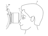
- FIG. 25 is an explanatory diagram for explaining the problem caused by the shortening of the working distance between the subject's eye E and the examination head 104.
- the distance between the subject's forehead and the examination head 104 is about 22 mm
- the distance between the subject's nose and the examination head 104 is about 2 mm
- the distance between the subject's cheek and the examination head 104 is about 28 mm. Therefore, the distance between the subject's nose and the examination head 104 is particularly shortened.
- the present invention was made in consideration of these circumstances, and aims to provide an ophthalmic device and an operating method for an ophthalmic device that can reliably prevent the examination head from coming close to the subject's nose.
- An ophthalmic device for achieving the object of the present invention includes an examination head for performing an examination of the subject's eye, a displacement mechanism for displacing the examination head relative to the subject's eye, a reference axis being an axis along the line of sight of the subject's eye parallel to the front-to-back direction which is the working distance direction of the examination head, and a tilt axis being an axis obtained by tilting the reference axis in an outward direction away from the subject's nose with the subject's eye as the center, a distance detection unit for detecting a face distance, which is the distance between the examination head and the subject's face, while the examination head is being displaced along the tilt axis by the displacement mechanism, and a retraction control unit for driving the displacement mechanism to rotate the examination head around a predetermined rotation axis in a direction in which the face distance increases, when the face distance detected by the distance detection unit falls below a predetermined threshold value.
- the rotation mechanism is driven to rotate the examination head, thereby preventing the examination head from approaching the subject's face.
- the distance detection unit detects the distance between the examination head and the subject's nose as the face distance. This makes it possible to prevent the examination head from coming close to the subject's nose.
- the displacement mechanism includes a moving mechanism that moves the examination head in the front-back, left-right, and up-down directions relative to the subject's eye, and a rotating mechanism that rotates the examination head around a rotation axis
- the retraction control unit executes a first retraction control that drives the rotating mechanism to rotate the examination head in a direction that increases the face distance, and a second retraction control that stops driving the moving mechanism or drives the moving mechanism to retract the examination head in a direction away from the face.
- the displacement mechanism includes a movement mechanism that moves the examination head in the front-back, left-right, and up-down directions relative to the subject's eye, and a rotation mechanism that rotates the examination head around a rotation axis, the examination head having an objective lens, the rotation mechanism rotates the examination head around the objective lens, and the movement mechanism moves the examination head and the rotation axis together in the front-back, left-right, and up-down directions.
- the rotation axis is parallel to the up-down direction, and the outward direction is parallel to the left-right direction.
- the rotation axis is perpendicular to the vertical direction, and the outward direction is upward in the vertical direction.
- the displacement mechanism includes a movement mechanism that moves the examination head in the front-back, left-right, and up-down directions relative to the subject's eye, and a rotation mechanism that rotates the examination head around a rotation axis, the examination head has an objective lens, the rotation axis is located forward in the front-back direction closer to the subject's eye than the objective lens, and the movement mechanism moves the examination head and the rotation axis together in the front-back, left-right, and up-down directions.
- the rotation axis is parallel to the up-down direction, and the outward direction is parallel to the left-right direction.
- the rotation axis is perpendicular to the vertical direction, and the outward direction is upward in the vertical direction.
- the distance detection unit includes a plurality of cameras provided on the examination head, and a detection control unit that continuously executes the following: image capture control for capturing images of the face from a plurality of different directions using the plurality of cameras while the examination head is displaced along the tilt axis by the displacement mechanism; and calculation of face distance based on the captured images of the face captured by each of the plurality of cameras. This allows the face distance to be continuously detected while the examination head is displaced along the tilt axis by the displacement mechanism.
- the distance detection unit includes a plurality of cameras provided on the examination head, a pre-imaging control unit that causes one specific camera among the plurality of cameras to capture an image of the nose when the examination head is in an initial position, and a detection control unit that continuously executes the following: imaging control that causes the specific camera to capture an image of the nose while the examination head is being displaced along the tilt axis by the displacement mechanism; and a calculation process that calculates the face distance by comparing an image of the nose newly captured by the specific camera with an image of the nose captured at the initial position.
- the distance detection unit includes a non-contact distance sensor provided on the examination head, and a detection control unit that continuously calculates the face distance based on the detection signal output from the distance sensor while the examination head is being displaced along the tilt axis by the displacement mechanism. This makes it possible to continuously detect the face distance while the examination head is being displaced along the tilt axis by the displacement mechanism.
- the operating method of an ophthalmic device for achieving the object of the present invention includes an operating head for an ophthalmic device equipped with an examination head for performing an examination of a subject's eye and a displacement mechanism for displacing the examination head relative to the subject's eye, the operating method including a reference axis being an axis along the line of sight of the subject's eye that is parallel to the front-to-back direction, which is the working distance direction of the examination head, and a tilt axis being an axis obtained by tilting the reference axis in an outward direction away from the subject's nose with the subject's eye at the center, and a drive control step for driving the displacement mechanism to displace the examination head along the tilt axis to an examination position for the subject's eye, a distance detection step for detecting a face distance, which is the distance between the examination head and the subject's face, while the examination head is being displaced along the tilt axis by the displacement mechanism, and a retraction control step for driving the displacement mechanism to
- the present invention can reliably prevent the test head from coming close to the subject's nose.
- FIG. 1 is a side view of an ophthalmic apparatus according to a first embodiment.
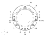
- 1 is a front view of the lens barrel as seen from the front side in the Z direction.
- 3 is a cross-sectional view of the lens barrel taken along line 3-3 in FIG. 2.
- 1 is a block diagram showing a configuration of an ophthalmic apparatus according to a first embodiment.
- FIG. 11 is an explanatory diagram for explaining a method of auto-alignment of an inspection head.
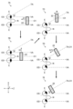
- FIG. 13 is an explanatory diagram for explaining a 1-1st example of auto-alignment of the inspection head in the first embodiment.
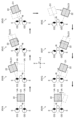
- FIG. 13 is an explanatory diagram for explaining a 1-2 example of auto-alignment of the inspection head in the first embodiment.
- FIGS. 11A to 11C are explanatory diagrams for explaining a first to third example of auto-alignment of the inspection head in the first embodiment.
- 11 is an explanatory diagram for explaining the possibility of the inspection head approaching the subject's face during auto-alignment.
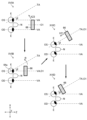
- FIG. 5 is an explanatory diagram for explaining retraction control of the inspection head according to the first embodiment;
- FIG. 13 is an explanatory diagram for explaining a modified example of the retraction control of the inspection head according to the first embodiment.
- FIG. 4 is a flowchart showing a flow of an examination process of an eye to be examined by the ophthalmologic apparatus of the first embodiment.
- 10 is a flowchart showing the flow of an auto-alignment process of the inspection head.
- FIG. 11 is an explanatory diagram for explaining the displacement of the inspection head after the start of auto-alignment.
- FIG. FIG. 13 is a side view of an ophthalmic apparatus according to a second embodiment.
- FIG. 13 is an explanatory diagram for explaining a 2-1st example of auto-alignment of the inspection head in the second embodiment.
- FIG. 13 is an explanatory diagram for explaining Example 2-2 of auto-alignment of the inspection head in the second embodiment.
- 13 is an explanatory diagram for explaining retraction control of the inspection head according to the second embodiment.
- FIG. FIG. 13 is a front view of a distal end surface of a lens barrel of an ophthalmic apparatus according to a third embodiment.
- FIG. 13 is a side view of an ophthalmic apparatus according to a fourth embodiment.
- FIG. 13 is an explanatory diagram for explaining a third example of auto-alignment of the inspection head in the fourth embodiment.
- FIG. FIG. 13 is a side view of an ophthalmic apparatus according to a fifth embodiment. 13 is an explanatory diagram for explaining a fourth example of auto-alignment of the inspection head in the fifth embodiment.
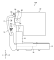
- FIG. 5 is an explanatory diagram for explaining the relationship between the lens size of an objective lens of an inspection head and the working distance of the inspection head.
- FIG. 11 is an explanatory diagram for explaining a problem that occurs when the working distance between the subject's eye and the examination head becomes shorter.
- FIG. 1 is a side view of an ophthalmic apparatus 10 according to a first embodiment.
- the X direction is the left-right direction based on a subject
- the Y direction is the up-down direction
- the Z direction is the front-back direction (also called the working distance direction) parallel to the front direction approaching the subject (subject's eye E) and the rear direction away from the subject.
- the ophthalmic device 10 is a multifunction device that combines a fundus camera that performs fundus photography of the subject's eye E and an optical coherence tomography device that uses OCT to obtain a tomographic image of the subject's eye E.
- the ophthalmic device 10 includes a base 12, a face support unit 14, an XZ movement mechanism 16, a Y movement mechanism 18, a swing rotation mechanism 20, and an examination head 22.
- a face support part 14 is attached to the front end part of the base 12 on the front side in the Z direction (the side of the subject's eye E).
- the base 12 is also provided with an XZ movement mechanism 16.
- the face support section 14 has a chin rest 14a and a forehead rest 14b whose position can be adjusted in the Y direction (up and down direction), and supports the subject's face in a position facing the examination head 22 (scope tube 28).
- the XZ movement mechanism 16 together with the Y movement mechanism 18 described below, constitutes the movement mechanism of the present invention.
- the XZ movement mechanism 16 includes a platform that is movable in the X and Z directions relative to the base 12, and an electric drive mechanism (a known actuator such as a motor drive mechanism) that moves the platform in the X and Z directions.
- This XZ movement mechanism 16 moves the Y movement mechanism 18, swing rotation mechanism 20, and inspection head 22 together in the X and Z directions.
- the Y movement mechanism 18 includes a lifting platform that is movable in the Y direction (not shown), and an electric drive mechanism that moves the lifting platform in the Y direction.
- This Y movement mechanism 18 moves the swing rotation mechanism 20 and the inspection head 22 together in the Y direction. This allows the swing rotation mechanism 20 and the inspection head 22 to be moved together in the X, Y and Z directions by the XZ movement mechanism 16 and the Y movement mechanism 18.
- the swing rotation mechanism 20 corresponds to the rotation mechanism of the present invention, and constitutes the displacement mechanism of the present invention together with the already described XZ movement mechanism 16 and Y movement mechanism 18.
- the swing rotation mechanism 20 is equipped with a rotation axis 20a parallel to the Y direction and an electric drive mechanism that rotates this rotation axis 20a, and rotates (swings) the inspection head 22 around the rotation axis 20a.
- the inspection head 22 is attached to the upper end of the rotation shaft 20a in the Y direction. This allows the inspection head 22 to be moved in the XYZ directions by the XZ movement mechanism 16 and the Y movement mechanism 18, and to be rotated around the axis of the rotation shaft 20a by the swing rotation mechanism 20.
- the examination head 22 is provided with a fundus camera unit 24 and an OCT unit 26, as shown in FIG. 4, which will be described later, and a lens barrel 28.
- the fundus camera unit 24 photographs the fundus of the subject's eye E through an objective lens 30, which will be described later, and outputs a fundus image, which is a front image of the fundus, to a control device 40 (see FIG. 4), which will be described later.
- the OCT unit 26 photographs the subject's eye E using OCT through the objective lens 30, and outputs detection signals and the like required to generate a tomographic image of the subject's eye E to the control device 40.
- the specific configurations of the fundus camera unit 24 and the OCT unit 26 are publicly known technologies (see Patent Document 1 above), so a detailed description will be omitted here.
- FIG. 2 is a front view of the lens barrel 28 as seen from the front side in the Z direction.
- FIG. 3 is a cross-sectional view of the lens barrel 28 along line 3-3 in FIG. 2.
- the lens barrel 28 is provided at the end of the inspection head 22 on the front side in the Z direction.
- the lens barrel 28 houses (holds) an objective lens 30 having an optical axis O1 (see FIG. 3) parallel to the Z direction.
- four illumination light sources 32 and a stereo camera 34 are provided on the lens barrel tip surface 28a on the front side in the Z direction of the lens barrel 28.
- a large lens compatible with wide-angle photography i.e., a lens with a short working distance, is used as the objective lens 30 (see FIG. 24).
- the type of objective lens 30 is not particularly limited, and a lens with a photography angle of view of about 45° may be used.
- the position of the rotation axis 20a and the position of the objective lens 30 coincide (including approximately coincidence, the same applies below).
- the inspection head 22 is rotated (swings) around the objective lens 30 by the swing rotation mechanism 20.
- the illumination light sources 32 are provided at both ends (left and right ends) of the telescope tube tip surface 28a in the X direction, and two are provided at the lower end of the telescope tube tip surface 28a, sandwiching a camera 34a (described below) between them.
- Each illumination light source 32 is, for example, an LED (Light Emitting Diode) light source, and illuminates the subject's eye E.
- the stereo camera 34 is used for alignment detection to detect the relative position of the subject's eye E in the XYZ directions with respect to the inspection head 22.
- the stereo camera 34 is composed of multiple cameras 34a.
- the stereo camera 34 is composed of three cameras 34a in total: two cameras 34a provided at both ends (left and right ends) in the X direction corresponding to the left and right positions of the objective lens 30 in the lens barrel tip surface 28a, and one camera 34a provided at the lower end corresponding to the lower position of the objective lens 30 in the lens barrel tip surface 28a.
- Each camera 34a simultaneously captures the anterior segment of the subject's eye E from multiple different directions (three directions in this embodiment) during alignment detection, and outputs multiple (three) anterior segment images of the subject's eye E to the control device 40 (see FIG. 4).
- the number of cameras 34a may be two or four or more.
- each camera 34a can be changed as appropriate. However, for example, if the camera 34a is provided in the upper region F1 (see FIG. 2) of the tube tip surface 28a, which is higher in the Y direction than both ends in the X direction, there is a risk that the pupil of the subject's eye E will be hidden by the subject's upper eyelashes when the camera 34a is used to photograph the subject's eye E. Furthermore, if the cameras 34a are provided in the left and right diagonally lower regions F2 (see FIG. 2) between both ends in the X direction and the lower end of the tube tip surface 28a, each camera 34a will be more likely to approach the subject's nose N (see FIG. 5) during alignment of the inspection head 22. For this reason, it is preferable to provide the cameras 34a at both ends in the X direction and the lower end of the tube tip surface 28a.
- FIG. 4 is a block diagram showing the configuration of the ophthalmic device 10 of the first embodiment.
- the ophthalmic device 10 in addition to the already-described XZ movement mechanism 16, Y movement mechanism 18, swing rotation mechanism 20, examination head 22, and stereo camera 34, the ophthalmic device 10 is provided with a fixation light emitter 36, a display unit 37, an operation unit 38, a memory unit 39, and a control device 40.
- the fixation light emitting unit 36 emits fixation light (bright spot image) toward the subject's eye E to guide and fix the gaze direction of the subject's eye E.
- the fixation light emitting unit 36 is composed of a known fixation target display unit, multiple fixation holes, and an external fixation lamp (see Patent Document 2 above).
- the fixation target display unit is provided inside the examination head 22 and is used for internal fixation, which projects fixation light (such as a bright spot image) onto the subject's eye E through the objective lens 30.
- Fixation hole is provided on the Z-direction front surface (or the tip surface 28a of the telescope tube) of the examination head 22 so as to surround the objective lens 30, and is used for peripheral fixation.
- Peripheral fixation is a fixation method in which the subject's eye E is rotated significantly in a desired direction by selectively lighting each fixation hole.
- the external fixation light is provided on the face support unit 14 or the examination head 22 and is used for external fixation.
- External fixation is a fixation method in which the subject's eye E is rotated in any direction by adjusting the light source position of the external fixation light, or the subject's eye E is rotated significantly more than when it is internally fixed, or the direction of the subject's eye E is adjusted by guiding the line of sight of the subject's eye E or the fellow eye when internal fixation cannot be performed.
- the display unit 37 is, for example, a touch panel monitor, and displays the setting screen of the ophthalmic device 10, the operation screen [UI (User Interface) screen] of the ophthalmic device 10, an image of the anterior segment of the subject's eye E captured by the stereo camera 34, and the examination results of the subject's eye E by the examination head 22 (fundus image and tomographic image of the subject's eye E).
- UI User Interface
- the operation unit 38 uses a known operation lever, switch, and operation screen displayed on the display unit 37.
- the operation unit 38 is used for inputting operations such as adjusting the position of the chin rest 14a and the forehead rest 14b, moving and rotating the examination head 22 in the XYZ directions, selecting the type of examination (fundus photography and OCT photography), switching between auto-alignment and manual alignment, starting the examination, and saving the examination results (fundus image, tomographic image).
- the memory unit 39 is a recording medium (storage medium) that stores the program executed by the control device 40, and various types of well-known storage may be used.
- the memory unit 39 also stores a fundus image of the subject's eye E captured by the fundus camera unit 24 and a tomographic image of the subject's eye E captured by the OCT unit 26 using OCT.
- the control device 40 controls the overall operation of each part of the ophthalmic device 10, and performs operations such as alignment of the examination head 22 with respect to the subject's eye E, fundus photography of the subject's eye E using the fundus camera unit 24, and OCT photography of the subject's eye E using the OCT unit 26.
- the control device 40 has an arithmetic circuit composed of various processors and memories, etc.
- the various processors include a CPU (Central Processing Unit), a GPU (Graphics Processing Unit), an ASIC (Application Specific Integrated Circuit), and programmable logic devices (e.g., SPLDs (Simple Programmable Logic Devices), CPLDs (Complex Programmable Logic Devices), and FPGAs (Field Programmable Gate Arrays)).
- the various functions of the control device 40 may be realized by a single processor, or by multiple processors of the same or different types.
- the control device 40 executes the control program stored in the memory unit 39, thereby functioning as a tilt angle determination unit 43, an alignment detection unit 44, a drive control unit 46, a detection control unit 47A, an evacuation control unit 47B, a fixation control unit 48, a measurement control unit 50, and a storage control unit 52.
- Figure 5 is an explanatory diagram for explaining the method of auto-alignment of the examination head 22.
- the symbol "OD" indicates the right eye (Oculus dexter) and the symbol “OS” indicates the left eye (Oculus sinister).
- the working distance of the examination head 22 becomes shorter due to the enlargement of the objective lens 30.
- symbol 5A in Figure 5 when the examination head 22 is moved forward in the Z direction from a position in front of the subject's eye E (here, the left eye OS) during auto-alignment of the examination head 22, there is a risk that the examination head 22 will come close to the subject's nose N.
- the examination head 22 is brought into close contact with the subject's eye E from an oblique direction when viewed from one side in the Y direction.
- the axis along the line of sight of the subject's eye E parallel to the Z direction is taken as the reference axis VA
- the direction in the X direction away from the nose N using the subject's eye E (here, the left eye OS) as the reference is taken as the outward direction X1
- the axis tilted from the reference axis VA in the outward direction X1 with the subject's eye E as the center is taken as the tilt axis TA.
- the examination head 22 when the examination head 22 is viewed from one side in the Y direction, it is displaced along the tilt axis TA to an examination position (hereinafter simply referred to as the examination position) where examination of the subject's eye E (fundus photography, OCT photography) can be performed.
- the "displacement” referred to here includes movement and rotation of the examination head 22 in the XYZ directions.
- the tilt angle determination unit 43 determines the tilt angle ⁇ of the tilt axis TA relative to the reference axis VA when viewed from one side in the Y direction, i.e., the tilt angle ⁇ of the tilt axis TA relative to the reference axis VA in the XZ plane. For example, the tilt angle determination unit 43 determines a value selected by the examiner using the operation unit 38 from among a plurality of angles (10°, 15°, 20°, etc.) as the tilt angle ⁇ , and outputs information on this tilt angle ⁇ to the drive control unit 46.
- the tilt angle determination unit 43 may also detect the relative position of the nose N with respect to the inspection head 22 based on the captured images obtained by stereoscopically photographing the nose N using the stereo camera 34, and determine the tilt angle ⁇ that can prevent the inspection head 22 from approaching the nose N based on the detection result.
- the alignment detection unit 44 detects the relative position of the subject's eye E with respect to the inspection head 22 by identifying the pupil center position of the subject's eye E and calculating the three-dimensional coordinates of this pupil center position based on the anterior ocular images of the subject's eye E stereoscopically photographed by each camera 34a of the stereo camera 34. Note that since the method of alignment detection using the stereo camera 34 is a publicly known technique (see Patent Document 1 above), a detailed description will be omitted here.
- the drive control unit 46 drives the XZ movement mechanism 16, the Y movement mechanism 18, and the swing rotation mechanism 20 to align the inspection head 22 with the subject's eye E and to switch the subject's eye E to be inspected (switch between left and right eye).
- Alignment of the inspection head 22 includes auto-alignment, which is performed by automatically driving the XZ movement mechanism 16, the Y movement mechanism 18, and the swing rotation mechanism 20, and manual alignment, which drives the XZ movement mechanism 16, the Y movement mechanism 18, and the swing rotation mechanism 20 in response to an input operation to the operation unit 38.
- the operation unit 38 is used to switch between auto-alignment and manual alignment.
- the drive control unit 46 determines the tilt axis TA corresponding to the tilt angle ⁇ based on the tilt angle ⁇ initially determined by the tilt angle determination unit 43.
- the drive control unit 46 first determines the reference axis VA based on the captured image obtained by stereoscopically capturing the subject's face (test eye E or nose N, etc.) using the stereo camera 34. Alternatively, the drive control unit 46 estimates the reference axis VA based on the Y-direction positions of the chin rest 14a and forehead rest 14b and the known discrimination information for the left eye OS and right eye OD. Then, the drive control unit 46 determines the axis tilted by angle ⁇ in the outward direction X1 from the reference axis VA centered on the test eye E as the tilt axis TA.
- the drive control unit 46 drives the XZ movement mechanism 16, the Y movement mechanism 18, and the swing rotation mechanism 20 based on the tilt axis TA to start auto-alignment, which automatically displaces the examination head 22 from the initial position at the time the ophthalmic device 10 is powered on to the examination position.
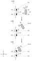
- FIG. 6 is an explanatory diagram for explaining a first example of auto-alignment of the inspection head 22 in the first embodiment.
- the inspection head 22 in the initial position, is positioned such that the optical axis O1 of the objective lens 30 is between the reference axes VA of the left and right test eyes E (left eye OS and right eye OD) when viewed from one side in the Y direction, that is, facing (including approximately facing, the same applies below) the nose N.
- the drive control unit 46 drives the XZ movement mechanism 16 to execute a first drive process that moves the inspection head 22 in the outward direction X1 from the initial position to the tilt axis TA when viewed from one side in the Y direction.
- the drive control unit 46 drives the swing rotation mechanism 20 after completing the first drive process to execute a second drive process in which the inspection head 22 is rotated by a tilt angle ⁇ around the rotation axis 20a (see arrow R).
- a tilt angle ⁇ around the rotation axis 20a (see arrow R).
- the optical axis O1 of the inspection head 22 becomes parallel to the tilt axis TA.
- the second drive process may be executed before the first drive process.
- the drive control unit 46 drives the XZ movement mechanism 16 to start a third drive process in which the examination head 22 is moved to the examination position along the tilt axis TA when viewed from one side in the Y direction (see arrow XZ1). This causes the examination head 22 to be moved toward the subject's eye E while keeping the tilt angle ⁇ constant (including approximately constant, the same applies below).
- the inspection head 22 is displaced to a position where the alignment detection unit 44 can identify the pupil center position of the test eye E, i.e., a position where alignment can be detected.
- the alignment detection result is input from the alignment detection unit 44 to the drive control unit 46.
- the Y-direction position adjustment of the inspection head 22 may be performed by the Y movement mechanism 18 even before alignment detection (at any stage of the first drive process to the third drive process) so that alignment detection by the alignment detection unit 44 is possible.
- the drive control unit 46 drives the XZ movement mechanism 16 and the Y movement mechanism 18 based on the alignment detection result input from the alignment detection unit 44, and continues the third drive process until the inspection head 22 reaches the inspection position. Note that, as will be described in detail later, if there is a risk that the inspection head 22 will come close to the subject's face (nose N) during the third drive process, retraction control of the inspection head 22 is executed. Furthermore, in the third drive process executed based on the alignment detection result, the position of the inspection head 22 in the Y direction is also adjusted.
- the drive control unit 46 drives the XZ movement mechanism 16 to first move the inspection head 22 forward in the Z direction (toward the subject's eye E) by a predetermined distance (see arrow Z1) as shown by reference numeral 7A in FIG. 7, and then executes a first drive process to move the inspection head 22 outward in the X1 direction to the tilt axis TA as shown by reference numeral 7B in FIG. 7.
- the movement distance of the inspection head 22 forward in the Z direction is not particularly limited as long as a safe distance can be secured between the inspection head 22 and the nose N. For example, this movement distance may be determined based on the result of calculating the Z direction distance from the inspection head 22 to the nose N based on the captured images obtained by stereoscopically capturing the nose N with the stereo camera 34.
- the drive control unit 46 drives the swing rotation mechanism 20 to execute a second drive process similar to the previously described example 1-1 (see reference symbol 6B in FIG. 6) to make the optical axis O1 parallel to the tilt axis TA.
- the second drive process may be executed before the first drive process.
- the drive control unit 46 drives the XZ movement mechanism 16 to execute a third drive process similar to the above-described example 1-1 (see reference numerals 6C and 6D in FIG. 6), thereby moving the inspection head 22 to the inspection position along the tilt axis TA when viewed from one side in the Y direction. Then, as shown by reference numeral 7E in FIG. 7, the drive control unit 46 drives the XZ movement mechanism 16 and the Y movement mechanism 18 based on the alignment detection detected by the alignment detection unit 44 during the auto-alignment, and continues the third drive process until the inspection head 22 reaches the inspection position, unless the retraction control described below is executed.
- FIG. 8 is an explanatory diagram for explaining a first-third example of auto-alignment of the inspection head 22 in the first embodiment.
- the drive control unit 46 drives the XZ movement mechanism 16, the Y movement mechanism 18, and the swing rotation mechanism 20 to execute a first drive process that simultaneously moves the inspection head 22 forward in the Z direction and outward in the X1 direction, and rotates the inspection head 22 at a tilt angle ⁇ (see arrows XZ2 and R).
- This makes it possible to move the inspection head 22 diagonally to the tilt axis TA when viewed from one side in the Y direction, and to make the optical axis O1 parallel to the tilt axis TA.
- the inspection head 22 may be displaced over the shortest distance to a position on the tilt axis TA where the stereo camera 34 can capture an image of the anterior segment of the subject's eye E, or to a position where an observation optical system (not shown) in the inspection head 22 can capture an image of the anterior segment of the subject's eye E.
- the drive control unit 46 drives the XZ movement mechanism 16 and the Y movement mechanism 18 to execute the second drive process after the first drive process is completed.
- the second drive process of Example 1-3 is the same process as the third drive process of Examples 1-1 and 1-2 described above, and moves the inspection head 22 to the inspection position along the tilt axis TA when viewed from one side in the Y direction.
- the drive control unit 46 drives the XZ movement mechanism 16 and the Y movement mechanism 18 based on the alignment detection detected by the alignment detection unit 44 during the auto-alignment, and continues the second drive process until the inspection head 22 reaches the inspection position, unless the evacuation control described below is executed.
- the drive control unit 46 drives the XZ movement mechanism 16 to retract the examination head 22 a predetermined distance backward in the Z direction (toward the examiner) (see symbols XIVD and XIVG in FIG. 14 described below).
- the drive control unit 46 drives at least the swing rotation mechanism 20 (the XZ movement mechanism 16 and the Y movement mechanism 18 may be driven simultaneously) to retract the examination head 22 from the subject's face (particularly the nose N).
- FIG. 9 is an explanatory diagram for explaining the possibility of the examination head 22 approaching the subject's face (particularly the nose N) during auto-alignment.
- the examination head 22 in auto-alignment, the examination head 22 is displaced along the tilt axis TA to the examination position of the subject's eye E (see arrow XZ1 in the figure), i.e., is brought close to the subject's eye E.
- the examination head 22 may approach the subject's face, particularly the nose N, as shown by reference numeral 9B in FIG. 9.
- evacuation control is executed to retract the examination head 22 from the subject's face.
- FIG. 10 is an explanatory diagram for explaining the retraction control of the inspection head 22 in the first embodiment.
- the detection control unit 47A together with the stereo camera 34, constitutes the distance detection unit of the present invention. While the inspection head 22 is displaced along the tilt axis TA to the examination position of the subject's eye E during auto-alignment, the detection control unit 47A controls the stereo camera 34 to continuously detect the facial distance Fd between the inspection head 22 and the subject's face.
- the facial distance Fd is the distance between the inspection head 22 and the nose N, which is particularly likely to be close to the part of the subject's face that the inspection head 22 is close to.
- the detection control unit 47A continuously (repeatedly) executes the following operations: image capture control for capturing images of the subject's face (nose N) from multiple different directions using each camera 34a of the stereo camera 34 while the inspection head 22 is displaced along the tilt axis TA; and captures images of the face from each camera 34a.
- each camera 34a of the stereo camera 34 it may be impossible to shoot the nose N with all of the cameras 34a.
- the subject eye E is the left eye OS
- only the camera 34a located to the right of the objective lens 30 as seen from the left eye OS may be able to shoot the nose N
- only the camera 34a located to the right and below the objective lens 30 may be able to shoot the nose N.
- the detection control unit 47A continuously photographs the face (nose N) using one or more cameras 34a capable of photographing the nose N on the tilt axis TA, and acquires the photographed image from the one or more cameras 34a that photograph the nose N.
- the camera 34a capable of photographing the nose N on the tilt axis TA in the stereo camera 34 can be determined based on left/right eye information indicating whether the subject eye E is the left eye OS or the right eye OD.
- the "multiple cameras 34a" referred to here is not limited to all cameras 34a.
- the detection control unit 47A When the face (nose N) is photographed by multiple cameras 34a, the detection control unit 47A repeatedly calculates the face distance Fd based on the photographed image of the face for each camera 34a each time it obtains a photographed image of the face from each camera 34a. For example, the detection control unit 47A analyzes the photographed image of each camera 34a using a known method to identify the nose contour from the background, identify the subject's cheek contour from the background, and identify the nostrils, thereby identifying the image of the nose N (nose tip) in each photographed image.
- the detection control unit 47A calculates the face distance Fd (the relative position of the nose N with respect to the inspection head 22), which is the shortest distance from the inspection head 22 to the nose N, based on the results of identifying the image of the nose N in the captured image for each camera 34a.
- the method of calculating the distance to various objects using the stereo camera 34 is a publicly known technique (see, for example, Patent Document 1), so a detailed explanation will be omitted here. This makes it possible to continuously detect the face distance Fd while the inspection head 22 is displaced along the tilt axis TA to the inspection position of the subject's eye E (see symbol XA in Figure 10).
- the detection control unit 47A performs photographing of the nose N using this camera 34a (corresponding to the specific camera of the present invention) at the initial position of the inspection head 22 to obtain a photographed image of the nose N.
- the detection control unit 47A functions as the pre-photography control unit of the present invention.
- the detection control unit 47A executes a calculation process to calculate the face distance Fd by comparing the size (magnification) of the outline of the image of the nose N contained in this image of the nose N with the outline of the image of the nose N contained in the image of the nose N at the initial position. This allows the face distance Fd to be detected continuously.
- the retraction control unit 47B executes retraction control by driving the swing rotation mechanism 20 to retract the examination head 22 from the subject's face (nose N) when the face distance Fd detected continuously by the detection control unit 47A becomes less than a predetermined threshold (see symbol XB in FIG. 10).
- the retraction control unit 47B executes retraction control by driving the swing rotation mechanism 20 as shown by symbol XC in FIG. 10 to rotate the examination head 22 in a direction in which the face distance Fd increases (see arrow R).
- the rotation direction of the examination head 22 in which the face distance Fd increases can be determined based on the above-mentioned left/right eye information, or the direction of the outward direction X1 (see symbol 6A in FIG. 6), etc.
- FIG. 11 is an explanatory diagram for explaining a modified example of the retraction control of the inspection head 22 of the first embodiment.
- the retraction control unit 47B may execute retraction control by driving both the swing rotation mechanism 20 and the XZ movement mechanism 16 when the face distance Fd continuously detected by the detection control unit 47A falls below a predetermined threshold value.
- the evacuation control unit 47B simultaneously executes the first evacuation control and the second evacuation control as evacuation control.
- the evacuation control unit 47B drives the swing rotation mechanism 20 to rotate the inspection head 22 in a direction in which the face distance Fd increases (see arrow R).
- the evacuation control unit 47B drives the XZ movement mechanism 16 to move the inspection head 22 in a direction away from the subject's face (nose N) (at least one of the X direction and the Z direction) (see arrow XZ3).
- the evacuation control unit 47B may drive the XZ movement mechanism 16 to evacuate the inspection head 22 in a direction away from the subject's face (at least one of the X direction and the Z direction) without driving the swing rotation mechanism 20.
- the inspection head 22 may be evacuated along the tilt axis TA, for example.
- the evacuation control unit 47B may drive the Y movement mechanism 18 instead of or together with the XZ movement mechanism 16 to move the inspection head 22 in the Y direction so that the inspection head 22 moves away from the subject's face (nose N).
- the drive control unit 46 drives the XZ movement mechanism 16 to move the examination head 22 backward in the Z direction (towards the examiner) by a predetermined distance (see symbols XIVD and XIVG in FIG. 14 described below).
- the fixation control unit 48 emits fixation light from the fixation light emission unit 36 at least from before the start of auto-alignment of the examination head 22 until the examination of the subject's eye E by the examination head 22 is completed. This makes it possible to guide and fix the subject's gaze direction in the direction of the fixation light while the examination head 22 is moved from the initial position via the tilt axis TA to the examination position during auto-alignment. Therefore, for example, when the examination head 22 is moved from the initial position to the tilt axis TA, the subject's eye E can be rotated to follow this movement (see Figures 6 to 8). As a result, the gaze direction of the subject's eye E can always be fixed to the examination head 22.
- the measurement control unit 50 controls fundus photography of the subject's eye E by the fundus camera unit 24, and tomographic image photography of the subject's eye E by the OCT unit 26. For example, after completing auto-alignment of the examination head 22, the measurement control unit 50 performs autofocus processing to drive a focus optical system (not shown) (see Patent Document 1) housed in the examination head 22 to focus the examination head 22 on the observed area (fundus, etc.) of the subject's eye E. Next, the measurement control unit 50 controls the fundus camera unit 24 to photograph the subject's eye E, or the OCT unit 26 to photograph the subject's eye E.
- a focus optical system not shown
- the measurement control unit 50 When the measurement control unit 50 performs fundus photography of the subject's eye E using the fundus camera unit 24, it acquires a fundus image of the subject's eye E from the fundus camera unit 24 and outputs it to the storage control unit 52.
- the measurement control unit 50 performs OCT photography of the subject's eye E using the OCT unit 26, it generates a tomographic image of the subject's eye E using a known method based on the detection signal output from the OCT unit 26, and outputs this tomographic image to the storage control unit 52.
- the storage control unit 52 causes the display unit 37 to display the fundus image or tomographic image of the subject's eye E input from the measurement control unit 50.
- the storage control unit 52 stores the fundus image or tomographic image of the subject's eye E in the memory unit 39.
- Fig. 12 is a flow chart showing the flow of the examination process of the subject's eye E by the ophthalmic apparatus 10 of the first embodiment having the above-mentioned configuration.
- the examiner operates the operation unit 38 to adjust the height positions (Y direction positions) of the chin rest 14a and the forehead rest 14b to suit the subject (step S1).
- the examiner then operates the operation unit 38 to select the type of examination for the subject's eye E (fundus photography by the fundus camera unit 24, OCT photography by the OCT unit 26) (step S2).
- the examiner also operates the operation unit 38 to select auto-alignment mode as the alignment mode for the examination head 22.
- the fixation control unit 48 causes the fixation light to be emitted from the fixation light emission unit 36 (step S3). This makes it possible to guide and fix the gaze direction of the subject's eye E.
- step S4 When the examiner inputs an operation to start the examination into the operation unit 38, automatic alignment of the examination head 22 with the subject's eye E is performed (step S4).
- FIG. 13 is a flow chart showing the flow of the auto-alignment process of the examination head 22 in the operating method of the ophthalmic apparatus of the present invention.
- FIG. 14 is an explanatory diagram for explaining the displacement of the examination head 22 after auto-alignment has started.
- the subject eye E is the left eye OS, and the explanation is given by taking as an example a case in which auto-alignment of "Example 1-1" shown in FIG. 6 is performed.
- the tilt angle determination unit 43 determines the angle previously selected by the examiner on the operation unit 38 as the tilt angle ⁇ , and then outputs information about this tilt angle ⁇ to the drive control unit 46 (step S4A). As a result, the drive control unit 46 determines the tilt axis TA based on this tilt angle ⁇ , and then starts auto-alignment of the inspection head 22 (step S4B).
- the drive control unit 46 drives the XZ movement mechanism 16 to execute a first drive process that first moves the inspection head 22 from the initial position to the tilt axis TA in the outward direction X1 when viewed from one side in the Y direction (step S4C).
- the alignment detection unit 44 starts capturing images with each camera 34a of the stereo camera 34, and continuously acquires captured images from each camera 34a and analyzes each captured image (step S4D).
- the drive control unit 46 drives the swing rotation mechanism 20 to rotate the inspection head 22 by the tilt angle ⁇ around the rotation axis 20a, thereby executing a second drive process to make the optical axis O1 of the inspection head 22 parallel to the tilt axis TA (step S4E).
- the inspection head 22 is displaced from the initial position shown by symbol XIVA in FIG. 14 to the tilt axis TA as shown by symbol XIVB, and the optical axis O1 becomes parallel to the tilt axis TA.
- the emission of fixation light from the fixation light emission unit 36 allows the line of sight of the subject's eye E to follow the displacement of the inspection head 22.
- the drive control unit 46 drives the XZ movement mechanism 16 to start a third drive process in which the inspection head 22 is moved to the inspection position along the tilt axis TA when viewed from one side in the Y direction, as shown by the symbol XIVC in FIG. 14 (step S4F, which corresponds to the drive control step of the present invention).
- step S4F which corresponds to the drive control step of the present invention.
- the detection control unit 47A continuously executes image capture control for capturing an image of the subject's face (nose N) using one or more cameras 34a capable of capturing an image of the nose N, and acquisition of captured images of the face from one or more cameras 34a capturing the image of the nose N. Then, when there are multiple cameras 34a capable of capturing an image of the nose N, the detection control unit 47A continuously executes calculation of the face distance Fd based on the captured images of the face for each camera 34a (step S4G, which corresponds to the distance detection step of the present invention).
- the detection control unit 47A calculates the face distance Fd based on the result of comparing this new image of the nose N with the image of the nose N in the initial position.
- the evacuation control unit 47B remains in standby mode until the face distance Fd falls below the threshold (NO in step S4H).
- the alignment detection unit 44 waits for alignment detection until the pupil center position of the test eye E can be identified from the captured images acquired by each camera 34a (NO in step S4I). Then, during auto-alignment, each camera 34a captures an image of the anterior segment of the test eye E, and the anterior segment image of the test eye E is input from each camera 34a to the alignment detection unit 44 as a captured image. This enables the alignment detection unit 44 to identify the pupil center position of the test eye E based on the anterior segment image input from each camera 34a (YES in step S4I).
- the alignment detection unit 44 performs alignment detection to detect the relative position of the test eye E with respect to the inspection head 22 by converting the pupil center position of the test eye E into three-dimensional coordinates (step S4J). Then, the alignment detection unit 44 outputs the detection result of the alignment detection to the drive control unit 46.
- the drive control unit 46 switches the alignment mode of the inspection head 22 to the manual alignment mode (the same applies to the second embodiment described below). This prevents the inspection head 22 from approaching the subject's eye E in a state where alignment detection is not possible.
- the evacuation control unit 47B maintains the standby state until the face distance Fd detected by the detection control unit 47A becomes less than the threshold value even after the alignment detection unit 44 detects the alignment (NO in step S4K).
- the drive control unit 46 drives the XZ movement mechanism 16 and the Y movement mechanism 18 based on the alignment detection result input from the alignment detection unit 44, and continues the third drive process until the inspection head 22 reaches the inspection position. Specifically, the drive control unit 46 calculates the difference between the three-dimensional coordinates (target coordinates) of the inspection position determined based on the alignment detection result and the three-dimensional coordinates (current coordinates) of the current inspection head 22, and continues the third drive process until this difference becomes equal to or less than the threshold value (step S4L, NO in step S4M, step S4N). As a result, the inspection head 22 is moved to the inspection position while maintaining the tilt angle ⁇ .
- the drive control unit 46 stops driving the XZ movement mechanism 16 and the Y movement mechanism 18 and ends the auto-alignment (YES in step S4M).
- step S4H if the face distance Fd detected by the detection control unit 47A during the third drive process becomes less than the threshold value, the evacuation control unit 47B operates (YES in step S4H or step S4K).
- the evacuation control unit 47B drives the swing rotation mechanism 20 to rotate the inspection head 22 as shown in FIG. 10, or drives the swing rotation mechanism 20 and the XZ movement mechanism 16 to simultaneously execute the first evacuation control and the second evacuation control as shown in FIG. 11 (step S4O).
- step S4O corresponds to the evacuation control step of the present invention. This prevents the inspection head 22 from approaching the nose N due to the movement of the subject's face, the shape and size of the subject's nose N, etc.
- the tilt angle determination unit 43 may determine a new tilt angle ⁇ (e.g., an angle larger than the previous tilt angle ⁇ ) and re-execute the third drive process along the tilt axis TA corresponding to this new tilt angle ⁇ , i.e., repeat the processes from step S4F onwards (the same applies to the second embodiment and onwards described below).
- a new tilt angle ⁇ e.g., an angle larger than the previous tilt angle ⁇
- the tilt angle determination unit 43 may determine a new tilt angle ⁇ (e.g., an angle larger than the previous tilt angle ⁇ ) and re-execute the third drive process along the tilt axis TA corresponding to this new tilt angle ⁇ , i.e., repeat the processes from step S4F onwards (the same applies to the second embodiment and onwards described below).
- the measurement control unit 50 drives the focus optical system (not shown) to perform auto-focus (step S5), and then causes the fundus camera unit 24 to perform fundus photography of the test eye E, or the OCT unit 26 to perform OCT photography of the test eye E (step S6).
- the measurement control unit 50 When the measurement control unit 50 has performed fundus photography, it outputs the fundus image of the test eye E acquired from the fundus camera unit 24 to the storage control unit 52.
- the measurement control unit 50 has performed OCT photography, it generates a tomographic image of the test eye E based on the detection signal output from the OCT unit 26, and outputs this tomographic image to the storage control unit 52.
- the drive control unit 46 drives the XZ movement mechanism 16 to move the examination head 22 backward in the Z direction, as shown by the symbol XIVD in Figure 14 (step S7).
- the storage control unit 52 causes the display unit 37 to display the fundus image or tomographic image of the subject's eye E input from the measurement control unit 50. This allows the examiner to check whether the desired fundus image or tomographic image has been obtained. If the desired fundus image or tomographic image has been obtained, the examiner inputs an image storage operation to the operation unit 38. This causes the storage control unit 52 to store the fundus image or tomographic image of the subject's eye E in the memory unit 39 (step S8).
- step S9 If the examination of the right eye OD is to be performed next, the processes from step S4 to step S8 are repeated (YES in step S9).
- the examination head 22 under the control of the drive control unit 46, the examination head 22 is displaced to the tilt axis TA corresponding to the right eye OD (see symbol XIVE in FIG. 14), and further moved along the tilt axis TA to the examination position of the right eye OD (see symbol XIVF in FIG. 14). Then, when the examination of the right eye OD is completed, under the control of the drive control unit 46, the examination head 22 is retreated to the rear side in the Z direction (see symbol XIVG in FIG. 14), and then displaced to the initial position (see symbol XIVH in FIG. 14).
- the swing rotation mechanism 20 can be driven to execute retraction control of the examination head 22. This makes it possible to reliably prevent the examination head 22 from approaching the nose N during auto-alignment, regardless of the movement of the subject's face or the shape and size of the subject's nose N.
- [Second embodiment] 15 is a side view of an ophthalmic apparatus 60 according to a second embodiment.
- the swing rotation mechanism 20 rotates (swings) the inspection head 22 around the objective lens 30, but the ophthalmic apparatus 60 according to the second embodiment includes an inspection head 66 whose rotation center position is different from that of the first embodiment.
- the ophthalmic device 60 is a fundus camera, and includes a base 12, a face support unit 14, an XZ movement mechanism 16, a fixation light emitter 36 (only the external fixation light is shown), a Y movement mechanism 62, a swing rotation mechanism 64, and an examination head 66.
- the ophthalmic device 60 also includes the stereo camera 34, display unit 37, operation unit 38, memory unit 39, and control device 40, which are not shown in the figure, as described in the first embodiment.
- the Y movement mechanism 62 together with the XZ movement mechanism 16, constitutes the movement mechanism of the present invention.
- the Y movement mechanism 62 has a shape that extends forward in the Z direction.
- a swing rotation mechanism 64 is provided at the tip of the Y movement mechanism 62 on the forward side in the Z direction.
- the Y movement mechanism 62 moves the swing rotation mechanism 64 and the inspection head 66 together in the Y direction.
- the XZ movement mechanism 16 and the Y movement mechanism 62 can move the swing rotation mechanism 64 and the inspection head 66 together in the X, Y and Z directions.
- the swing rotation mechanism 64 corresponds to the rotation mechanism of the present invention, and together with the XZ movement mechanism 16 and the Y movement mechanism 62 described above, constitutes the displacement mechanism of the present invention.
- the swing rotation mechanism 64 has a rotation axis 64a parallel to the Y direction, and rotates the inspection head 66 around this rotation axis 64a.
- the rotation axis 64a is provided forward in the Z direction from the lens barrel 28 (objective lens 30) of the inspection head 66. This allows the rotation axis 64a to be aligned with the subject's eye E (center of rotation) when viewed from one side in the Y direction by adjusting the XZ position of the swing rotation mechanism 64 with the XZ movement mechanism 16. In this case, the swing rotation mechanism 64 rotates (swings) the inspection head 66 around the center of rotation of the subject's eye E.
- the swing rotation mechanism 64 can also rotate (tilt) the inspection head 66 around a rotation axis perpendicular to the Y direction.
- the inspection head 66 is attached to a swing rotation mechanism 64. This allows the inspection head 66 to be moved in the XYZ directions by the XZ movement mechanism 16 and the Y movement mechanism 62, and to be rotated around the axis of rotation 64a by the swing rotation mechanism 64.
- This inspection head 66 is provided with the fundus camera unit 24 and the lens barrel 28 (including the stereo camera 34) described in the first embodiment.
- the control device 40 of the second embodiment is basically the same as the control device 40 of the first embodiment described above, except that the method of auto-alignment of the inspection head 66 by the drive control unit 46 is different.
- the drive control unit 46 determines the tilt axis TA based on the tilt angle ⁇ determined by the tilt angle determination unit 43, and then drives the XZ movement mechanism 16, the Y movement mechanism 62, and the swing rotation mechanism 64 to perform auto-alignment of the inspection head 66.
- FIG. 16 is an explanatory diagram for explaining a second example of auto-alignment of the inspection head 66 in the second embodiment. As shown by reference symbol XVIA in FIG. 16, the inspection head 66 is initially placed in the same initial position as in the first embodiment.
- the drive control unit 46 drives the XZ movement mechanism 16 to execute a first drive process for moving the examination head 66 (swing rotation mechanism 64) from the initial position in the XZ direction (see arrow XZ2). Specifically, when viewed from one side in the Y direction, the examination head 66 is moved in the XZ direction to a position where the rotation axis 64a coincides with the center of rotation of the subject's eye E.
- the drive control unit 46 drives the swing rotation mechanism 20 to execute a second drive process in which the examination head 66 is rotated by a tilt angle ⁇ around the rotation axis 20a (center of rotation of the subject's eye E) (see arrow R).
- a tilt angle ⁇ around the rotation axis 20a (center of rotation of the subject's eye E) (see arrow R).
- the examination head 66 is moved to the tilt axis TA and the optical axis O1 becomes parallel to the tilt axis TA.
- the drive control unit 46 drives the XZ movement mechanism 16 to start a third drive process in which the inspection head 66 is moved to the inspection position along the tilt axis TA when viewed from one side in the Y direction, as in the first embodiment (see arrow XZ1).
- the third drive process in the second embodiment mainly involves Z-axis movement of the inspection head 66 by the XZ movement mechanism 16. As a result, the inspection head 66 is moved toward the subject's eye E while maintaining a constant tilt angle ⁇ .
- the drive control unit 46 drives the XZ movement mechanism 16 and the Y movement mechanism 62 based on the alignment detection detected by the alignment detection unit 44 during the auto-alignment, and continues the third drive process until the inspection head 66 reaches the inspection position.
- FIG. 17 is an explanatory diagram for explaining Example 2-2 of auto-alignment of the inspection head 66 in the second embodiment.
- the drive control unit 46 simultaneously drives the XZ movement mechanism 16, the Y movement mechanism 62, and the swing rotation mechanism 64 to execute a first drive process that simultaneously moves the inspection head 66 in the XZ directions and rotates the inspection head 66 at a tilt angle ⁇ (see arrows XZ2 and R).
- the first drive process of Example 2-2 is a process that simultaneously executes the first drive process and the second drive process of Example 2-1 described in FIG. 16.
- the inspection head 66 is moved to the tilt axis TA, and the optical axis O1 of the objective lens 30 becomes parallel to the tilt axis TA.
- the inspection head 66 may be displaced over the shortest distance on the tilt axis TA to a position where the stereo camera 34 can capture an image of the anterior segment of the subject's eye E, or to a position where an observation optical system (not shown) in the inspection head 22 can capture an image of the anterior segment of the subject's eye E.
- the drive control unit 46 drives the XZ movement mechanism 16 and the Y movement mechanism 62 to execute a second drive process similar to the third drive process of the above-mentioned "Example 2-1", thereby moving the inspection head 66 to the inspection position along the tilt axis TA when viewed from one side in the Y direction (see arrow XZ1). Then, as shown by symbol XVIIC in FIG. 17, the drive control unit 46 continues the second drive process by driving the XZ movement mechanism 16 and the Y movement mechanism 62 based on the alignment detection detected by the alignment detection unit 44 during the auto-alignment, unless the retraction control is executed, until the inspection head 66 reaches the inspection position.
- FIG. 18 is an explanatory diagram for explaining the retraction control of the inspection head 66 in the second embodiment.
- the detection control unit 47A in the second embodiment continuously calculates the face distance Fd in the same manner as in the first embodiment while the inspection head 66 is being displaced along the tilt axis TA to the inspection position of the subject's eye E.
- the evacuation control unit 47B of the second embodiment executes evacuation control by driving the swing rotation mechanism 64 when the face distance Fd detected by the detection control unit 47A falls below a predetermined threshold, and rotating the inspection head 66 around the rotation axis 64a in a direction in which the face distance Fd increases (see arrow R).
- the evacuation control unit 47B may drive at least one of the XZ movement mechanism 16 and the Y movement mechanism 62 simultaneously with the swing rotation mechanism 64 to move the inspection head 66 in a direction in which the face distance Fd increases while rotating it.
- the ophthalmic device 10 of the second embodiment by executing the evacuation control when the face distance Fd falls below a predetermined threshold, it is possible to reliably prevent the examination head 22 from approaching the subject's nose N during auto-alignment, as in the first embodiment described above.
- [Third embodiment] 19 is a front view of the lens barrel tip surface 28a of the ophthalmic apparatus 10 of the third embodiment.
- the detection control unit 47A of the ophthalmic apparatus 10 of each of the above embodiments detects the face distance Fd by using the stereo camera 34, but the face distance Fd may be detected by using another method.
- the ophthalmic device 10 of the third embodiment has basically the same configuration as the ophthalmic device 10 of each of the above embodiments (the same applies to the fourth and fifth embodiments described below), except that it is equipped with multiple non-contact distance measuring sensors 70. For this reason, parts that are the same in function or configuration as the ophthalmic device 10 of each of the above embodiments are given the same reference numerals and their description is omitted.
- Each distance measurement sensor 70 together with the detection control unit 74A, constitutes the distance detection unit of the present invention, and is provided, for example, on the end surface 28a of the lens barrel. Note that each distance measurement sensor 70 may be provided at a location other than the end surface 28a of the lens barrel 28, or on the front surface of the housing of the inspection head 22, 66. There may also be only one distance measurement sensor 70. As each distance measurement sensor 70, for example, a photoelectric sensor, optical fiber sensor, laser sensor, camera-integrated laser displacement sensor, ultrasonic sensor, or capacitance sensor may be used.
- the detection control unit 47A of the third embodiment continuously acquires the detection signals output from each distance measurement sensor 70 and calculates the face distance Fd based on the detection signals of each distance measurement sensor 70 while the examination head 22 is displaced along the tilt axis TA to the examination position of the subject's eye E.
- the evacuation control unit 47B of the third embodiment can also drive at least the swing rotation mechanism 64 to perform evacuation control of the examination heads 22, 66 similar to the above embodiments when the face distance Fd detected by the detection control unit 47A falls below a predetermined threshold.
- the third embodiment is also effective in cases where the position of the subject's face shifts during auto-alignment, causing the face distance Fd to fall below the threshold.
- [Fourth embodiment] 20 is a side view of an ophthalmic device 10A of the fourth embodiment.
- the ophthalmic device 10 of the first embodiment includes a swing rotation mechanism 20 having a rotation axis 20a parallel to the Y direction, and moves the inspection head 22 close to the subject's eye E along a tilt axis TA obtained by tilting the reference axis VA in the X direction (outward direction X1) with the subject's eye E as the center during auto-alignment of the inspection head 22.
- the ophthalmic device 10A of the fourth embodiment moves the inspection head 22 close to the subject's eye E along a tilt axis TA obtained by tilting the reference axis VA in a direction other than the X direction with the subject's eye E as the center during auto-alignment of the inspection head 22.
- the ophthalmic device 10A of the fourth embodiment has basically the same configuration as the ophthalmic device 10 of the first embodiment, except that it is equipped with a tilt rotation mechanism 80 and performs auto-alignment of the examination head 22, which is different from the first embodiment. Therefore, parts that are the same in function or configuration as the ophthalmic device 10 of the first embodiment are given the same reference numerals and their description is omitted.
- the tilt rotation mechanism 80 corresponds to the rotation mechanism of the present invention, and constitutes the displacement mechanism of the present invention together with the already described XZ movement mechanism 16, Y movement mechanism 18, and swing rotation mechanism 20.
- the tilt rotation mechanism 80 is equipped with a rotation axis 80a perpendicular to the Y direction and an electric drive mechanism that rotates this rotation axis 80a, and rotates (tilts) the inspection head 22 around the rotation axis 80a.
- the rotation shaft 80a When the rotation shaft 80a is viewed from one side in the axial direction, the position of the rotation shaft 80a and the position of the objective lens 30 coincide (including approximately coincidence, the same applies below). As a result, the inspection head 22 is rotated (tilted) around the objective lens 30 by the tilt rotation mechanism 80.
- the inspection head 22 of the fourth embodiment can rotate (swing and tilt) around two axes around the objective lens 30 by the swing rotation mechanism 20 and the tilt rotation mechanism 80. Therefore, the inspection head 22 of the fourth embodiment can rotate around any rotation axis perpendicular to the Z direction (including other than the rotation axes 20a and 80a) by driving at least one of the swing rotation mechanism 20 and the tilt rotation mechanism 80.
- a direction other than the outward direction X1 of the first embodiment (a direction perpendicular to the Z direction and away from the nose N), for example, upward in the Y direction, is defined as the "outward direction Y1 (see FIG. 21)," and the axis obtained by tilting the reference axis VA in the "outward direction Y1" around the subject's eye E is defined as the tilt axis TA.
- the control device 40 of the fourth embodiment is basically the same as the control device 40 of the first embodiment, except that the tilt direction of the tilt axis TA differs from that of the first embodiment.
- the tilt angle determination unit 43 of the fourth embodiment determines the tilt angle ⁇ of the tilt axis TA in the outward direction Y1 (see FIG. 21) relative to the reference axis VA when viewed from one side in the X direction, i.e., the tilt angle ⁇ of the tilt axis TA relative to the reference axis VA in the YZ plane.
- the specific method of determining the tilt angle ⁇ is the same as the method of determining the tilt angle ⁇ in the first embodiment above, except for the tilt direction of the tilt axis TA, so a detailed explanation will be omitted here.
- the drive control unit 46 of the fourth embodiment determines the tilt axis TA based on the tilt angle ⁇ determined by the tilt angle determination unit 43, and then drives the XZ movement mechanism 16, the Y movement mechanism 18, the swing rotation mechanism 20, and the tilt rotation mechanism 80 to perform auto-alignment of the inspection head 22.
- FIG. 21 is an explanatory diagram for explaining a third example of auto-alignment of the inspection head 22 in the fourth embodiment. Note that this third example is basically the same as the 1-1 example (see FIG. 6) described in the first embodiment above, except that the tilt direction of the tilt axis TA is different.
- the inspection head 22 is initially placed in the same initial position as in the first embodiment.
- the drive control unit 46 in the fourth embodiment drives the XZ movement mechanism 16 and the Y movement mechanism 18 to execute a first drive process that moves the inspection head 22 from the initial position in the outward direction Y1 (upward in the Y direction) to the tilt axis TA when viewed from one side in the X direction.
- the drive control unit 46 drives the tilt rotation mechanism 80 to execute a second drive process in which the inspection head 22 is rotated by a tilt angle ⁇ around the rotation axis 80a (see arrow R).
- the optical axis O1 of the inspection head 22 becomes parallel to the tilt axis TA.
- the second drive process may be executed before the first drive process.
- the drive control unit 46 drives the XZ movement mechanism 16 and the Y movement mechanism 18 to start a third drive process in which the examination head 22 is moved to the examination position along the tilt axis TA when viewed from one side in the X direction (see arrow YZ1). This causes the examination head 22 to move toward the subject's eye E while keeping the tilt angle ⁇ constant (including approximately constant, the same applies below).
- the drive control unit 46 drives the XZ movement mechanism 16 and the Y movement mechanism 18 based on the alignment detection detected by the alignment detection unit 44 during the auto-alignment, and continues the third drive process until the inspection head 22 reaches the inspection position.
- the drive control unit 46 switches the alignment mode of the inspection head 22 to the manual alignment mode.
- the inspection head 22 may first be moved a predetermined distance forward in the Z direction (toward the subject's eye E), and then the first drive process described above may be started.
- the first drive process may be executed to simultaneously move the inspection head 22 forward in the Z direction and outward in the Y1 direction and rotate the inspection head 22 at the tilt angle ⁇ .
- the examination head 22 can be moved along the tilt axis TA from an oblique direction (diagonally upward) to the examination position of the subject's eye E during auto-alignment. As a result, the same effect as in the first embodiment can be obtained.
- the inspection head 22 is brought closer to the subject's eye E along a tilt axis TA that tilts the reference axis VA in the outward direction Y1 (upward in the Y direction) with the subject's eye E as the center, but the tilt direction of this tilt axis TA is not particularly limited as long as it is perpendicular to the Z direction and moves away from the nose N. Furthermore, the direction of the rotation axes 20a, 80a can also be changed as appropriate depending on this tilt direction.
- the swing rotation mechanism 20 may be omitted.
- [Fifth embodiment] 22 is a side view of an ophthalmic device 60A of the fifth embodiment.
- the ophthalmic device 10 of the second embodiment includes a swing rotation mechanism 64 having a rotation axis 64a (corresponding to the first rotation axis of the present invention) parallel to the Y direction, and moves the inspection head 66 close to the subject's eye E along a tilt axis TA obtained by tilting the reference axis VA in the X direction (outward direction X1) with the subject's eye E as the center during auto-alignment of the inspection head 66.
- the ophthalmic device 60A of the fifth embodiment moves the inspection head 66 close to the subject's eye E along a tilt axis TA obtained by tilting the reference axis VA in a direction other than the X direction with the subject's eye E as the center during auto-alignment of the inspection head 66, similar to the ophthalmic device 10A of the fourth embodiment.
- the ophthalmic device 60A of the fifth embodiment has basically the same configuration as the ophthalmic device 60 of the second embodiment, except that it is equipped with a tilt rotation mechanism 90 and performs auto-alignment of the examination head 66, which is different from the second embodiment. Therefore, parts that are the same in function or configuration as the ophthalmic device 60 of the second embodiment are given the same reference numerals and their description is omitted.
- the tilt rotation mechanism 90 corresponds to the rotation mechanism of the present invention, and constitutes the displacement mechanism of the present invention together with the already described XZ movement mechanism 16, Y movement mechanism 62, and swing rotation mechanism 64.
- the tilt rotation mechanism 90 rotates (tilts) the inspection head 66 around a virtual rotation axis 90a (corresponding to the second rotation axis of the present invention) perpendicular to the Y direction.
- the tilt rotation mechanism 90 is composed of, for example, a curved arm 92, multiple guide wheels 93, and a head movement mechanism (not shown).
- the curved arm 92 is fixed to the swing rotation mechanism 64, and has a shape that follows an arc-shaped trajectory centered on the rotation axis 90a.
- the multiple guide wheel portions 93 are held inside the inspection head 66 so that they can rotate freely around a central axis that is parallel to the rotation axis 90a. These guide wheel portions 93 are arranged so as to sandwich the curved arm 92 in the Y direction. This allows the inspection head 66 to move along the curved arm 92.
- the head movement mechanism (not shown) of the tilt rotation mechanism 90 is provided inside the inspection head 66 and moves the inspection head 66 along the curved arm 92.
- this head movement mechanism is a publicly known technique (for example, JP 2022-112637 A), so a detailed description will be omitted here.
- the inspection head 66 can be rotated (tilted) around the rotation axis 90a.
- the inspection head 66 can be rotated (tilted) around the subject's eye E.
- the examination head 66 of the fifth embodiment can rotate (swing and tilt) on two axes, similar to the examination head 22 of the fourth embodiment, by the swing rotation mechanism 64 and the tilt rotation mechanism 90. Therefore, the examination head 66 of the fifth embodiment can also rotate around any rotation axis perpendicular to the Z direction (including other than the rotation axes 64a and 90a) by driving at least one of the swing rotation mechanism 64 and the tilt rotation mechanism 90.
- a direction other than the outward direction X1 of the second embodiment (a direction perpendicular to the Z direction and away from the nose N), for example, the upward Y direction as in the fourth embodiment, is defined as the "outward direction Y1", and the axis obtained by tilting the reference axis VA in the outward direction Y1 around the subject's eye E is defined as the tilt axis TA.
- the control device 40 of the fifth embodiment is basically the same as the control device 40 of the second embodiment, except that the tilt direction of the tilt axis TA differs from that of the second embodiment.
- the tilt angle determination unit 43 of the fifth embodiment determines the tilt angle ⁇ of the tilt axis TA in the outward direction Y1 relative to the reference axis VA, similar to the tilt angle determination unit 43 of the fourth embodiment.
- the drive control unit 46 of the fifth embodiment determines the tilt axis TA based on the tilt angle ⁇ determined by the tilt angle determination unit 43, and then drives the XZ movement mechanism 16, the Y movement mechanism 62, the swing rotation mechanism 64, and the tilt rotation mechanism 90 to perform auto-alignment of the inspection head 66.
- FIG. 23 is an explanatory diagram for explaining a fifth example of auto-alignment of the inspection head 66 in the fifth embodiment.
- This fifth example is basically the same as the second example (see FIG. 16) described in the second embodiment above, except for the inclination direction of the tilt axis TA.
- the inspection head 66 is initially placed in the same initial position as in the first embodiment.
- the drive control unit 46 executes a first drive process in which the XZ movement mechanism 16 and the Y movement mechanism 62 are driven to move the examination head 66 in the XYZ directions to a position where the rotation axis 64a and the rotation axis 90a coincide with the center of rotation of the subject's eye E.
- the drive control unit 46 drives the tilt rotation mechanism 90 to execute a second drive process in which the inspection head 66 is rotated in the outward direction Y1 by a tilt angle ⁇ around the rotation axis 90a (center of rotation of the subject's eye E) (see arrow R).
- a tilt angle ⁇ around the rotation axis 90a (center of rotation of the subject's eye E) (see arrow R).
- the inspection head 66 is moved to the tilt axis TA and the optical axis O1 becomes parallel to the tilt axis TA.
- the drive control unit 46 drives the XZ movement mechanism 16 and the Y movement mechanism 62 to start a third drive process in which the examination head 66 is moved to the examination position along the tilt axis TA when viewed from one side in the X direction (see arrow YZ1). This causes the examination head 66 to move toward the subject's eye E while keeping the tilt angle ⁇ constant (including approximately constant, the same applies below).
- the drive control unit 46 drives the XZ movement mechanism 16 and the Y movement mechanism 62 based on the alignment detection detected by the alignment detection unit 44 during the auto-alignment, and continues the third drive process until the inspection head 66 reaches the inspection position.
- the drive control unit 46 switches the alignment mode of the inspection head 66 to manual alignment mode.
- first drive process and the second drive process may be performed simultaneously, as in Example 2-2 of the auto-alignment of the inspection head 66 in the second embodiment described above (see FIG. 17).
- the examination head 66 can be moved along the tilt axis TA from an oblique direction (diagonally upward) to the examination position of the subject's eye E during auto-alignment. As a result, the same effect as in the second embodiment can be obtained.
- the inspection head 66 is brought closer to the subject's eye E along a tilt axis TA that is formed by tilting the reference axis VA in the outward direction Y1 (upward in the Y direction) with the subject's eye E as its center.
- the tilt direction of the tilt axis TA with the subject's eye E as its center is not particularly limited as long as it is perpendicular to the Z direction and moves away from the nose N.
- the direction of the rotation axes 64a, 90a can also be changed as appropriate depending on this tilt direction.
- the swing rotation mechanism 64 may be omitted.
- alignment detection and evacuation control are performed using the stereo camera 34, but alignment detection and evacuation control may be performed using an observation optical system (not shown) housed in the inspection head 22, 66. In this case, the stereo camera 34 and the distance measurement sensor 70 can be omitted.
- the stereo camera 34 is provided on the end surface 28a of the lens barrel, but the inspection head 22, 66 may have the stereo camera 34 provided at a position other than the end surface 28a of the lens barrel.
- the inspection heads 22, 66 are moved to the examination position of the subject's eye E along the tilt axis TA with the tilt angle ⁇ determined by the tilt angle determination unit 43, but during manual alignment, the inspection heads 22, 66 may also be moved to the examination position of the subject's eye E along the tilt axis TA with the tilt angle ⁇ . Even in this case, when the face distance Fd falls below a predetermined threshold, the evacuation control unit 47B automatically executes evacuation control.
- the distance between the inspection head 22, 66 and the nose N is detected as the face distance Fd under the control of the detection control unit 47A, but the distance between the inspection head 22, 66 and parts of the subject's face other than the nose N may also be detected.
- the displacement mechanism for displacing the examination head 22, 66 relative to the subject eye E is configured with an XZ movement mechanism 16, a Y movement mechanism 18, 62, and a swing rotation mechanism 20, 64, and is further configured with a tilt rotation mechanism 80, 90.
- this displacement mechanism are not particularly limited.
- a robot arm multi-joint arm
- the displacement mechanism of the present invention may be used as the displacement mechanism of the present invention.
- a combined fundus camera and optical coherence tomograph and a fundus camera alone have been used as examples of the ophthalmic device 10, but the present invention is not limited to this.
- the present invention can also be applied to various ophthalmic devices (including devices that perform various treatments on the subject's eye E, such as laser surgery devices) used to examine the subject's eye E (measuring eye characteristics, photographing, and observing), such as an optical coherence tomograph alone and an SLO device, and that perform alignment of various examination heads on the subject's eye E.
- Evacuation control section 4 8...Fixation control unit 50...Measurement control unit 52...Storage control unit 60...Ophthalmic device 62...Y movement mechanism 64...Swing rotation mechanism 64a...Rotation axis 66...Inspection head 70...Distance measurement sensor 74A...Detection control unit 80, 90...Tilt rotation mechanism 80a, 90a...Rotation axis 100...Objective lens 102...Objective lens 104...Inspection head E...Subject's eye F1...Upper region F2...Lower region Fd...Facial distance H...Subject N...Nose O1...Optical axis OD...Right eye OS...Left eye R...Arrow TA...Tilt axis VA...Reference axis X1...Outward direction Y1...Outward direction d1...Working distance d2...Working distance ⁇ ...Tilt angle
Landscapes
- Health & Medical Sciences (AREA)
- Life Sciences & Earth Sciences (AREA)
- Engineering & Computer Science (AREA)
- Heart & Thoracic Surgery (AREA)
- Molecular Biology (AREA)
- Biophysics (AREA)
- Ophthalmology & Optometry (AREA)
- Biomedical Technology (AREA)
- Veterinary Medicine (AREA)
- Medical Informatics (AREA)
- Physics & Mathematics (AREA)
- Surgery (AREA)
- Animal Behavior & Ethology (AREA)
- General Health & Medical Sciences (AREA)
- Public Health (AREA)
- Signal Processing (AREA)
- Nuclear Medicine, Radiotherapy & Molecular Imaging (AREA)
- Radiology & Medical Imaging (AREA)
- Eye Examination Apparatus (AREA)
Priority Applications (3)
| Application Number | Priority Date | Filing Date | Title |
|---|---|---|---|
| EP23930839.8A EP4670618A1 (en) | 2023-03-28 | 2023-11-17 | OPHTHALMIC DEVICE AND METHOD OF USING AN OPHTHALMIC DEVICE |
| CN202380096615.6A CN121001645A (zh) | 2023-03-28 | 2023-11-17 | 眼科装置以及眼科装置的工作方法 |
| JP2025509698A JPWO2024202212A1 (https=) | 2023-03-28 | 2023-11-17 |
Applications Claiming Priority (2)
| Application Number | Priority Date | Filing Date | Title |
|---|---|---|---|
| JP2023052057 | 2023-03-28 | ||
| JP2023-052057 | 2023-03-28 |
Publications (1)
| Publication Number | Publication Date |
|---|---|
| WO2024202212A1 true WO2024202212A1 (ja) | 2024-10-03 |
Family
ID=92903834
Family Applications (1)
| Application Number | Title | Priority Date | Filing Date |
|---|---|---|---|
| PCT/JP2023/041452 Ceased WO2024202212A1 (ja) | 2023-03-28 | 2023-11-17 | 眼科装置及び眼科装置の作動方法 |
Country Status (4)
| Country | Link |
|---|---|
| EP (1) | EP4670618A1 (https=) |
| JP (1) | JPWO2024202212A1 (https=) |
| CN (1) | CN121001645A (https=) |
| WO (1) | WO2024202212A1 (https=) |
Citations (7)
| Publication number | Priority date | Publication date | Assignee | Title |
|---|---|---|---|---|
| JP2007282671A (ja) * | 2006-04-12 | 2007-11-01 | Nidek Co Ltd | 眼科装置 |
| JP2012170590A (ja) * | 2011-02-21 | 2012-09-10 | Canon Inc | 検眼装置及びその制御方法 |
| JP2012239472A (ja) * | 2011-05-13 | 2012-12-10 | Canon Inc | 眼圧計測装置及びその制御方法 |
| JP2013248376A (ja) | 2012-05-01 | 2013-12-12 | Topcon Corp | 眼科装置 |
| JP2021069415A (ja) | 2019-10-29 | 2021-05-06 | 株式会社トプコン | 眼科装置及びその制御方法 |
| JP2022104668A (ja) * | 2020-12-29 | 2022-07-11 | 株式会社トプコン | 眼科装置 |
| JP2022112637A (ja) | 2021-01-22 | 2022-08-03 | 株式会社トプコン | 眼科装置 |
-
2023
- 2023-11-17 JP JP2025509698A patent/JPWO2024202212A1/ja active Pending
- 2023-11-17 WO PCT/JP2023/041452 patent/WO2024202212A1/ja not_active Ceased
- 2023-11-17 CN CN202380096615.6A patent/CN121001645A/zh active Pending
- 2023-11-17 EP EP23930839.8A patent/EP4670618A1/en active Pending
Patent Citations (7)
| Publication number | Priority date | Publication date | Assignee | Title |
|---|---|---|---|---|
| JP2007282671A (ja) * | 2006-04-12 | 2007-11-01 | Nidek Co Ltd | 眼科装置 |
| JP2012170590A (ja) * | 2011-02-21 | 2012-09-10 | Canon Inc | 検眼装置及びその制御方法 |
| JP2012239472A (ja) * | 2011-05-13 | 2012-12-10 | Canon Inc | 眼圧計測装置及びその制御方法 |
| JP2013248376A (ja) | 2012-05-01 | 2013-12-12 | Topcon Corp | 眼科装置 |
| JP2021069415A (ja) | 2019-10-29 | 2021-05-06 | 株式会社トプコン | 眼科装置及びその制御方法 |
| JP2022104668A (ja) * | 2020-12-29 | 2022-07-11 | 株式会社トプコン | 眼科装置 |
| JP2022112637A (ja) | 2021-01-22 | 2022-08-03 | 株式会社トプコン | 眼科装置 |
Non-Patent Citations (1)
| Title |
|---|
| See also references of EP4670618A1 |
Also Published As
| Publication number | Publication date |
|---|---|
| CN121001645A (zh) | 2025-11-21 |
| JPWO2024202212A1 (https=) | 2024-10-03 |
| EP4670618A1 (en) | 2025-12-31 |
Similar Documents
| Publication | Publication Date | Title |
|---|---|---|
| JP5955193B2 (ja) | 眼科装置および眼科装置の制御方法並びにプログラム | |
| JP6641730B2 (ja) | 眼科装置、および眼科装置用プログラム | |
| WO2021085020A1 (ja) | 眼科装置及びその制御方法 | |
| JP7459491B2 (ja) | 眼科測定装置 | |
| JP2017213124A (ja) | 眼科装置 | |
| JP6600215B2 (ja) | 眼科装置 | |
| JP2020124350A (ja) | 眼科装置 | |
| JP7637487B2 (ja) | 眼底カメラ及びその制御方法 | |
| JP6239872B2 (ja) | 眼科装置及び眼科装置の制御方法 | |
| JP7344055B2 (ja) | 眼科装置及び眼科装置の制御方法 | |
| JP6736356B2 (ja) | 眼科装置 | |
| JP7550672B2 (ja) | 眼科装置及びその制御方法 | |
| JP7550586B2 (ja) | 眼科装置及びその作動方法 | |
| JP2022080459A (ja) | 眼科装置、および眼科装置制御プログラム | |
| WO2024202212A1 (ja) | 眼科装置及び眼科装置の作動方法 | |
| JP2018015021A (ja) | 眼科装置 | |
| US20260020758A1 (en) | Ophthalmic device and method for operating ophthalmic device | |
| WO2024202210A1 (ja) | 眼科装置及び眼科装置の作動方法 | |
| WO2024202213A1 (ja) | 眼科装置及び眼科装置の作動方法 | |
| JP7434729B2 (ja) | 眼科装置、および眼科装置制御プログラム | |
| JP6930841B2 (ja) | 眼科装置 | |
| JP2023034685A (ja) | 眼科装置 | |
| JP7423912B2 (ja) | 眼科装置、および眼科装置制御プログラム | |
| JP2026006091A (ja) | 眼科装置 | |
| JP2025024370A (ja) | スリットランプ |
Legal Events
| Date | Code | Title | Description |
|---|---|---|---|
| 121 | Ep: the epo has been informed by wipo that ep was designated in this application |
Ref document number: 23930839 Country of ref document: EP Kind code of ref document: A1 |
|
| ENP | Entry into the national phase |
Ref document number: 2025509698 Country of ref document: JP Kind code of ref document: A |
|
| WWE | Wipo information: entry into national phase |
Ref document number: 2025509698 Country of ref document: JP Ref document number: 2023930839 Country of ref document: EP |
|
| NENP | Non-entry into the national phase |
Ref country code: DE |
|
| ENP | Entry into the national phase |
Ref document number: 2023930839 Country of ref document: EP Effective date: 20250926 |
|
| ENP | Entry into the national phase |
Ref document number: 2023930839 Country of ref document: EP Effective date: 20250926 |
|
| WWP | Wipo information: published in national office |
Ref document number: 2023930839 Country of ref document: EP |