WO2024202147A1 - 切断システム、設定方法、及び、切断品の製造方法 - Google Patents
切断システム、設定方法、及び、切断品の製造方法 Download PDFInfo
- Publication number
- WO2024202147A1 WO2024202147A1 PCT/JP2023/037159 JP2023037159W WO2024202147A1 WO 2024202147 A1 WO2024202147 A1 WO 2024202147A1 JP 2023037159 W JP2023037159 W JP 2023037159W WO 2024202147 A1 WO2024202147 A1 WO 2024202147A1
- Authority
- WO
- WIPO (PCT)
- Prior art keywords
- cutting
- factors
- level
- levels
- cut
- Prior art date
- Legal status (The legal status is an assumption and is not a legal conclusion. Google has not performed a legal analysis and makes no representation as to the accuracy of the status listed.)
- Ceased
Links
Images




Classifications
-
- B—PERFORMING OPERATIONS; TRANSPORTING
- B24—GRINDING; POLISHING
- B24B—MACHINES, DEVICES, OR PROCESSES FOR GRINDING OR POLISHING; DRESSING OR CONDITIONING OF ABRADING SURFACES; FEEDING OF GRINDING, POLISHING, OR LAPPING AGENTS
- B24B27/00—Other grinding machines or devices
- B24B27/06—Grinders for cutting-off
-
- B—PERFORMING OPERATIONS; TRANSPORTING
- B24—GRINDING; POLISHING
- B24B—MACHINES, DEVICES, OR PROCESSES FOR GRINDING OR POLISHING; DRESSING OR CONDITIONING OF ABRADING SURFACES; FEEDING OF GRINDING, POLISHING, OR LAPPING AGENTS
- B24B49/00—Measuring or gauging equipment for controlling the feed movement of the grinding tool or work; Arrangements of indicating or measuring equipment, e.g. for indicating the start of the grinding operation
-
- H—ELECTRICITY
- H10—SEMICONDUCTOR DEVICES; ELECTRIC SOLID-STATE DEVICES NOT OTHERWISE PROVIDED FOR
- H10P—GENERIC PROCESSES OR APPARATUS FOR THE MANUFACTURE OR TREATMENT OF DEVICES COVERED BY CLASS H10
- H10P95/00—Generic processes or apparatus for manufacture or treatments not covered by the other groups of this subclass
Definitions
- the present invention relates to a cutting system, a setting method, and a method for manufacturing cut products.
- Patent Document 1 JP 2007-125667 A discloses a substrate cutting device.
- This cutting device includes a chuck table that holds the substrate, and a cutting blade that cuts the substrate held on the chuck table.
- the substrate is cut by moving the chuck table while the cutting blade is rotating (see Patent Document 1).
- Patent Document 1 does not disclose a means for solving such a problem.
- the present invention has been made to solve these problems, and its purpose is to provide a cutting system, setting method, and manufacturing method for cut products that can efficiently derive appropriate cutting conditions.
- a cutting system includes a cutting mechanism and a control unit.
- the cutting mechanism cuts the object to be cut.
- the control unit controls the cutting mechanism to produce cut products by cutting the object to be cut according to the cutting conditions.
- the cutting conditions include a plurality of factors.
- the control unit obtains a plurality of levels for each factor included in the cutting conditions, generates a plurality of combinations, each of which is a combination of levels selected one for each factor, according to an experimental design method, controls the cutting mechanism to produce cut products for each combination of levels by cutting the object to be cut according to each of the plurality of combinations, and determines a level for actual production or a level candidate for actual production for each factor based on an evaluation value of each cut product produced for each combination of levels.
- a setting method is a setting method in which a computer sets cutting conditions when cutting an object to be cut with a cutting mechanism to produce cut products.
- the cutting conditions include a plurality of factors.
- the computer executes the steps of acquiring a plurality of levels for each factor included in the cutting conditions, generating a plurality of combinations, each of which is a combination of levels selected one for each factor, according to an experimental design method, controlling the cutting mechanism to produce cut products for each combination of levels by cutting the object to be cut according to each of the plurality of combinations, and determining, for each factor, a level to be set as a level for actual production or a candidate level for actual production, based on an evaluation value of each cut product produced for each combination of levels.
- a method for manufacturing cut products uses the above-mentioned cutting system, and includes a step of determining the level to be set as the level for actual production for each factor, and a step of manufacturing the cut products by cutting the object to be cut according to the combination of each level set as the level for actual production.
- a method for manufacturing a cut product according to another aspect of the present invention includes a step in which a computer sets cutting conditions according to the above-mentioned setting method, and a step in which the cut product is manufactured by cutting the object to be cut according to the set cutting conditions.
- the present invention provides a cutting system, setting method, and manufacturing method for cut products that can efficiently derive appropriate cutting conditions.
- FIG. 2 is a plan view showing a schematic diagram of a cutting device.
- 10 is a diagram illustrating a schematic view of an electronic component being photographed by a second optical inspection camera;
- FIG. FIG. 2 is a diagram illustrating a hardware configuration of a computer.
- 10 is a flowchart showing a procedure for deriving an appropriate cutting condition.
- FIG. 13 is a diagram for explaining an input screen for a plurality of factors, etc.;
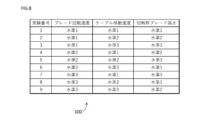
- FIG. 1 is a diagram illustrating an example of an orthogonal table.
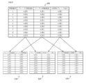
- FIG. 9 is a diagram for explaining that the table shown in FIG. 8 is an orthogonal table.
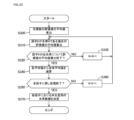
- FIG. 10 is a flowchart showing the procedure of an analysis process executed in step S135 of FIG. 9 .
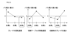
- FIG. 11 is a diagram for explaining a procedure for determining level candidates for production in step S370 in FIG. 10.
- FIG. 1 is a diagram illustrating an example in which a plurality of computers control and inspect operations.
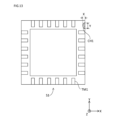
- FIG. 1 is a diagram for explaining the size of chipping in an electronic component.
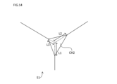
- 1A and 1B are diagrams for explaining the size of chipping at a corner of an electronic component.
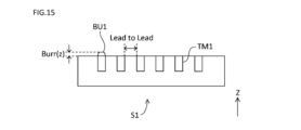
- 11A and 11B are diagrams for explaining the height direction length of the burrs and the distance between terminals.
- FIG. 1 is a plan view showing a schematic diagram of a cutting device 1 according to the present embodiment.
- the cutting device 1 is configured to cut a package substrate (one example of an object to be cut) to separate the package substrate into a plurality of electronic components (one example of cut products).
- a substrate or a lead frame to which a semiconductor chip is fixed is sealed with resin.
- the object to be cut does not necessarily have to be a package substrate, and may be, for example, a substrate (including a wafer) that is not sealed with resin.
- the object to be cut may also be a substrate to which a semiconductor chip is not fixed.
- the cut product is, for example, a substrate on which wiring is printed.
- package substrates include BGA (Ball Grid Array) package substrates, LGA (Land Grid Array) package substrates, CSP (Chip Size Package) package substrates, LED (Light Emitting Diode) package substrates, and QFN (Quad Flat No-leaded) package substrates.
- the cutting device 1 is also configured to inspect each of the multiple individual electronic components.
- each electronic component is photographed and inspected based on the photographed image. Inspection data is generated through this inspection, and each electronic component is classified as either a "good product” or a "defective product.”
- a package substrate P1 is used as the object to be cut, and the cutting device 1 separates the package substrate P1 into a plurality of electronic components S1 (see FIG. 2).
- the surface that is sealed with resin is referred to as the mold surface
- the surface opposite the mold surface is referred to as the ball/lead surface. Note that, if the object to be cut is a substrate that is not sealed with resin, the surface that faces upwards when cutting (the cut surface) corresponds to the ball/lead surface in this embodiment, and the surface opposite the cut surface corresponds to the mold surface in this embodiment.
- the cutting device 1 includes, as its components, a cutting module A1 and an inspection and storage module B1.
- the cutting module A1 is configured to manufacture a plurality of electronic components S1 by cutting a package substrate P1.
- the inspection and storage module B1 is configured to inspect each of the manufactured plurality of electronic components S1, and then store the electronic components S1 in a tray. In the cutting device 1, each component is detachable and replaceable with respect to the other components.
- the cutting module A1 mainly includes a substrate supply unit 3, a positioning unit 4, a cutting table 5, a spindle unit 6, and a transport unit 7.
- the board supply unit 3 supplies the package boards P1 one by one to the positioning unit 4 by pushing the package boards P1 out one by one from a magazine M1 that contains multiple package boards P1. At this time, the package boards P1 are arranged with the ball/lead surface facing upwards.
- the positioning unit 4 positions the package substrate P1 by placing the package substrate P1 pushed out from the substrate supply unit 3 on the rail portion 4a. The positioning unit 4 then transports the positioned package substrate P1 to the cutting table 5.
- the cutting table 5 holds the package substrate P1 to be cut.
- a cutting device 1 with a twin-cut table configuration having two cutting tables 5 is illustrated.
- the cutting table 5 includes a holding member 5a, a rotation mechanism 5b, and a movement mechanism 5c.
- the holding member 5a holds the package substrate P1 transported by the positioning unit 4 by suctioning it from below.
- the rotation mechanism 5b is capable of rotating the holding member 5a on a horizontal plane in the ⁇ 1 direction in the figure.
- the movement mechanism 5c is capable of moving the holding member 5a along the Y axis in the figure.
- the spindle unit 6 cuts the package substrate P1 to separate the package substrate P1 into a plurality of electronic components S1.
- a cutting device 1 having a twin spindle configuration with two spindle units 6 is shown as an example.
- the spindle unit 6 is movable along the X-axis and Z-axis in the figure.
- the cutting device 1 may also have a single spindle configuration with one spindle unit 6.
- the spindle portion 6 includes a rotating shaft 6c.
- a blade 6a is fixed to the rotating shaft 6c of the spindle portion 6.
- the blade 6a cuts the package substrate P1 by rotating at high speed, and separates the package substrate P1 into a plurality of electronic components S1.
- the blade 6a is attached to the rotating shaft 6c while being clamped by first and second flanges (not shown).
- the first and second flanges are fixed to the rotating shaft 6c by fastening members (not shown), such as nuts.
- the cutting module A1 is provided with a cutting water nozzle, a cooling water nozzle, a scrap-blowing water nozzle, etc. (not shown).
- the cutting water nozzle sprays cutting water towards the blade 6a which rotates at high speed.
- the cooling water nozzle sprays cooling water towards the vicinity of the cutting point of the package substrate P1.
- the scrap-blowing water nozzle sprays scrap-blowing water to blow away cutting chips, etc.
- the package substrate P1 is imaged by the first position confirmation camera 5d, and the position of the package substrate P1 is confirmed.
- the confirmation using the first position confirmation camera 5d is, for example, confirmation of the position of an alignment mark provided on the package substrate P1.
- the position information of the alignment mark is used, for example, to determine the cutting line for the package substrate P1.
- the cutting table 5 moves toward the spindle unit 6 along the Y axis in the figure.
- the cutting table 5 and the spindle unit 6 are moved relative to each other to cut the package substrate P1.
- the cutting table 5 moves in the Y axis direction in the figure relative to the blade 6a to cut the package substrate P1.
- the package substrate P1 is imaged by the second position confirmation camera 6b provided in the cutting module A1, and the position of the package substrate P1, etc., is confirmed.
- the confirmation using the second position confirmation camera 6b is, for example, confirmation of the cutting position and cutting width of the package substrate P1.
- the cutting table 5 moves away from the spindle portion 6 along the Y axis in the figure with the multiple individual electronic components S1 adsorbed thereto.
- the first cleaner 5e cleans and dries the top surface (ball/lead surface) of the electronic component S1. This cleaning may be performed, for example, by spraying cleaning water directly onto the top surface of the electronic component S1, or by supplying cleaning water to the top surface of the electronic component S1 via a brush or the like.
- the cutting device 1 is provided with two first cleaners 5e aligned in the X axis direction in the figure, but the number of first cleaners 5e is not limited to this.
- the transport unit 7 picks up the electronic component S1 held on the cutting table 5 from above and transports the electronic component S1 to the inspection table 11 of the inspection and storage module B1.
- the second cleaner 7a cleans and dries the underside (molded surface) of the electronic component S1. This cleaning may be performed, for example, by spraying cleaning water directly onto the underside of the electronic component S1, or by supplying cleaning water to the underside of the electronic component S1 via a brush or the like.
- the inspection and storage module B1 mainly includes an inspection table 11, a first optical inspection camera 12, a second optical inspection camera 13, a placement unit 14, and an extraction unit 15.
- the first optical inspection camera 12 may be provided in the cutting module A1.
- the inspection table 11 holds the electronic component S1 for optical inspection of the electronic component S1.
- the inspection table 11 is movable along the X-axis in the figure.
- the inspection table 11 can also be turned upside down.
- the inspection table 11 is provided with a holding member 11b (see FIG. 2) that holds the electronic component S1 by suction.
- the first optical inspection camera 12 and the second optical inspection camera 13 respectively photograph the mold surface and the ball/lead surface of the electronic component S1. Based on the image data generated by the first optical inspection camera 12 and the second optical inspection camera 13, various inspections (visual inspections) relating to the appearance of the electronic component S1 are performed. Examples of visual inspections include inspection of the size of the electronic component S1, inspection of the size of the terminals TM1 (see FIG. 6), and inspection of the length between adjacent terminals TM1.
- the first optical inspection camera 12 and the second optical inspection camera 13 are each positioned near the inspection table 11 so as to photograph the upward direction.
- the first optical inspection camera 12 photographs the mold surface of the electronic component S1 being transported to the inspection table 11 by the transport unit 7.
- the transport unit 7 then places the electronic component S1 on the holding member 11b of the inspection table 11. After the holding member 11b adsorbs the electronic component S1, the inspection table 11 is turned upside down.
- the inspection table 11 moves above the second optical inspection camera 13, and the ball/lead surface of the electronic component S1 is photographed by the second optical inspection camera 13.
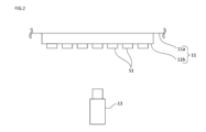
- FIG. 2 is a schematic diagram showing how electronic components S1 are photographed by the second optical inspection camera 13.
- the inspection table 11 includes an inspection table main body 11a and a holding member 11b.
- the holding member 11b is provided below the inspection table main body 11a.
- a plurality of electronic components S1 held by suction by the holding member 11b are photographed by the second optical inspection camera 13.
- An inspection of the appearance of the ball/lead surface of each electronic component S1 is performed based on the image data generated by the second optical inspection camera 13.
- the placement unit 14 places the inspected electronic component S1.
- the placement unit 14 is movable along the Y axis in the figure.
- the inspection table 11 places the inspected electronic component S1 on the placement unit 14.
- the extraction unit 15 transfers the electronic components S1 placed in the placement unit 14 to a tray.
- the electronic components S1 are sorted into "good” or “defective” based on the results of inspection using the first optical inspection camera 12 and the second optical inspection camera 13.
- the extraction unit 15 transfers each electronic component S1 to a good-product tray 15a or a defective-product tray 15b based on the results of the sorting. That is, good products are stored in the good-product tray 15a, and defective products are stored in the defective-product tray 15b.
- the good-product tray 15a and the defective-product tray 15b are each filled with electronic components S1, they are replaced with a new tray.
- the cutting device 1 further includes a computer 50 and a monitor 20.
- the monitor 20 is configured to display an image.
- the monitor 20 is configured with a display device such as a liquid crystal monitor or an organic EL (Electro Luminescence) monitor.
- the monitor 20 is provided, for example, on the front side of the cutting device 1.
- the computer 50 controls the operation of each part of, for example, the cutting module A1 and the inspection and storage module B1.
- the computer 50 controls the operation of, for example, the board supply unit 3, the positioning unit 4, the cutting table 5, the spindle unit 6, the transport unit 7, the inspection table 11, the first optical inspection camera 12, the second optical inspection camera 13, the placement unit 14, the extraction unit 15, and the monitor 20.
- the computer 50 also performs various inspections of the electronic component S1 based on, for example, image data generated by the first optical inspection camera 12 and the second optical inspection camera 13. Next, the computer 50 will be described in detail.
- Fig. 3 is a diagram illustrating a hardware configuration of the computer 50. As illustrated in Fig. 3, the computer 50 includes a control unit 70, an input/output I/F (interface) 90, a reception unit 95, and a storage unit 80, and each component is electrically connected via a bus.
- I/F input/output
- a reception unit 95 reception unit
- a storage unit 80 storage unit
- the control unit 70 includes a CPU (Central Processing Unit) 72, a RAM (Random Access Memory) 74, and a ROM (Read Only Memory) 76.
- the control unit 70 is configured to control each component in the computer 50 and each component in the cutting device 1 in accordance with information processing.
- the input/output I/F 90 is configured to communicate with each component included in the cutting device 1 via a signal line.
- the input/output I/F 90 is used to transmit data from the computer 50 to each component in the cutting device 1, and to receive data transmitted from each component in the cutting device 1 to the computer 50.
- the reception unit 95 is configured to receive instructions from a user.
- the reception unit 95 is configured, for example, with some or all of a touch panel, a keyboard, a mouse, and a microphone.
- the storage unit 80 is, for example, an auxiliary storage device such as a hard disk drive or a solid state drive.
- the storage unit 80 is configured to store, for example, a control program 81.
- the control program 81 is executed by the control unit 70 to realize various operations in the cutting device 1.
- the control unit 70 executes the control program 81, the control program 81 is deployed in the RAM 74.
- the control unit 70 then controls each component by interpreting and executing the control program 81 deployed in the RAM 74 using the CPU 72.
- the cutting table 5 is moved relative to the rotating blade 6a to cut the package substrate P1.
- the cutting of the package substrate P1 is performed according to preset cutting conditions.
- the cutting conditions include a plurality of factors. Examples of the plurality of factors include the rotation speed of the blade 6a, the relative movement speed of the cutting table 5 with respect to the blade 6a when cutting the package substrate P1, the position of the blade 6a in the height direction (Z direction in FIG.
- the cutting sequence (the sequence indicating the order in which the cutting is performed from which position on the package substrate P1), the amount and temperature of cutting water used during cutting, the amount and temperature of cooling water used during cutting, and the amount and temperature of scrap-removing water used during cutting.
- the cutting conditions include various factors.
- various levels can be set for each factor. Since there are many patterns for combinations of levels selected one by one for each factor (hereinafter simply referred to as "combinations"), it takes a long time to cut the package substrate P1 for all combination patterns. In addition, there is a limit to the number of package substrates P1 that can be used to set the cutting conditions. Therefore, it is not realistic to cut the package substrate P1 for all combination patterns.
- the user sets the cutting conditions based on past experience.
- the cutting conditions that are set depend on the user's experience, and appropriate cutting conditions may not be set depending on the user's experience.
- the user performs multiple cuts while manually changing the cutting conditions, a lot of manual work is required, making it difficult to efficiently derive appropriate cutting conditions.
- the combinations used to derive the cutting conditions are automatically generated according to an experimental design method. Therefore, the cutting device 1 can efficiently derive appropriate cutting conditions by cutting the package substrate P1 according to some combinations without cutting the package substrate P1 according to all combinations of the levels of each factor. Furthermore, in the cutting device 1, since the cutting conditions are automatically determined based on multiple combinations generated according to an experimental design method, appropriate cutting conditions can be derived stably compared to, for example, a case in which the cutting conditions are determined by a user performing multiple cuts while manually changing the cutting conditions.
- an orthogonal array including a plurality of combinations is generated in order to derive cutting conditions.
- the orthogonal array will be described in detail later.
- Information on factors and levels required to generate the orthogonal array is input by a user.
- the package substrate P1 is cut according to each of the plurality of combinations included in the orthogonal array, and electronic components S1 are manufactured for each combination.
- evaluation values hereinafter also referred to as "evaluation values”
- candidate levels for the actual production are determined.
- the evaluation parameters are criteria for evaluating each electronic component S1 manufactured by using each combination included in the orthogonal array. The evaluation parameters will be described later.
- the package substrate P1 is cut according to the candidate level for actual production, and the reproducibility of the candidate level for actual production is confirmed. If there is no problem with the reproducibility of the candidate level for actual production, the candidate level for actual production is determined as the level for actual production. The operation of deriving the cutting conditions in the cutting device 1 is described in detail below.
- FIG. 4 is a flowchart showing the procedure for deriving appropriate cutting conditions. The process shown in this flowchart is executed by the control unit 70 of the computer 50 when, for example, the production of a new type of electronic component S1 is started and an operation for automatically setting the cutting conditions is performed by the user.
- control unit 70 of the computer 50 receives inputs regarding a plurality of factors, a plurality of levels for each of the plurality of factors, and an evaluation parameter (step S100). These inputs are made, for example, via the reception unit 95 of the computer 50.
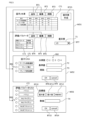
- FIG. 5 is a diagram for explaining the input screen for multiple factors, etc.
- input screen WD1 when the user performs an operation to automatically set the cutting conditions, input screen WD1 is displayed on monitor 20.
- Input screen WD1 includes tables CT1 and CT2.
- Table CT1 shows the currently input factors and levels.
- button BT1 is selected, or when button BT2 is selected with any row included in table CT1 selected, input screen WD2 is displayed on monitor 20.
- button BT3 is selected with any row included in table CT1 selected, the selected row is deleted from table CT1.
- the input screen WD2 is a screen for directly inputting factors and levels.
- a number of factors are listed in the list LT1, and a factor to be added or edited is selected via the radio button RB1.
- examples of options include the relative movement speed of the cutting table 5 with respect to the blade 6a when cutting the package substrate P1, the height position of the blade 6a when cutting the package substrate P1, and the rotation speed of the blade 6a.
- the number of levels to be associated with the factor is selected via the radio button RB2.
- the reference value of the level is input in the area T2.
- the reference value of the level refers to the minimum value of the multiple levels to be associated with the factor.
- the interval (difference) between the levels is input in the area T3. Multiple levels are automatically generated by inputting the reference value and interval of the level.
- Table CT2 included in input screen WD1 shows the currently entered evaluation parameters.
- button BT4 is selected, or when button BT5 is selected with any row included in table CT2 selected, input screen WD3 is displayed on monitor 20.
- button BT6 is selected with any row included in table CT2 selected, the selected row is deleted from table CT2.
- the input screen WD3 is a screen for directly inputting evaluation parameters.
- a number of evaluation parameters are listed in the list LT2, and the evaluation parameter to be added or edited is selected via the radio button RB3.
- examples of options include burr (x), burr (y), package size (x), package size (Y), package offset (x), and package offset (y).
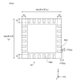
- FIG. 6 is a diagram for explaining each evaluation parameter.
- burr (x) is, for example, the length in the X direction of burr BU1 protruding from terminal TM1.
- Burr (y) is, for example, the length of the portion of burr BU1 protruding from terminal TM1 in the Y direction.
- PKG size (x) is the length in the X direction of electronic component S1
- PKG size (y) is the length in the Y direction of electronic component S1.
- PKG offset (x) is (X1+X2)/2
- PKG offset (y) is (Y1+Y2)/2.
- buttons BT10, BT11, or BT12 by selecting any of buttons BT10, BT11, or BT12, the target value of the selected evaluation parameter is input.
- button BT10 the maximum value becomes the target value
- button BT11 the minimum value becomes the target value.
- button BT12 the specific value input in area T4 becomes the target value.
- burr (x) is selected as the evaluation parameter
- package size (x) is selected as the evaluation parameter
- button BT13 the input contents on input screen WD3 are reflected in table CT2, and when button BT14 is selected, the input contents on input screen WD3 are canceled.
- a list of types of orthogonal tables that can be generated is displayed in pull-down format.
- types of orthogonal tables include the L4 orthogonal table, L8 orthogonal table, L16 orthogonal table, L32 orthogonal table, L64 orthogonal table, L128 orthogonal table, L256 orthogonal table, L9 orthogonal table, L27 orthogonal table, L81 orthogonal table, L249 orthogonal table, L18 orthogonal table, L36 orthogonal table, L54 orthogonal table, L108 orthogonal table, L25 orthogonal table, and L50 orthogonal table.
- Each orthogonal table requires a different number of factors and levels. In the cutting device 1, when button BT7 is selected, only the orthogonal tables that can be generated using the factors and levels entered in table CT1 are displayed in pull-down format.
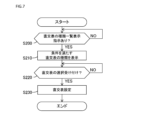
- FIG. 7 is a flowchart showing the procedure for displaying a list of orthogonal array types. The process shown in this flowchart is executed by the control unit 70 of the computer 50 when the input screen WD1 is displayed on the monitor 20.
- control unit 70 of the computer 50 determines whether an instruction to display the list of orthogonal array types has been received (whether button BT7 has been selected) (step S200). If it is determined that an instruction to display the list of orthogonal array types has not been received (NO in step S200), the control unit 70 repeats the process of step S200 until an instruction to display the list of orthogonal array types is received.
- control unit 70 extracts types of orthogonal arrays that can be generated based on the factors and the number of levels listed in table CT1 ( Figure 5), and controls the monitor 20 to display the extracted types of orthogonal arrays in a pull-down format.
- the control unit 70 determines whether any of the types of orthogonal arrays listed in the pull-down menu extending upward or downward from area T1 has been selected (step S220). If it is determined that a type of orthogonal array has not been selected (NO in step S220), the control unit 70 repeats the processing of step S220 until a type of orthogonal array has been selected. On the other hand, if it is determined that a type of orthogonal array has been selected (YES in step S220), the control unit 70 sets the selected type of orthogonal array and controls the monitor 20 to display the set type of orthogonal array in area T1 (step S230).
- the cutting device 1 input regarding each of the multiple factors and the multiple levels of each factor is performed via the reception unit 95 of the computer 50. Therefore, the cutting device 1 allows the user to easily input regarding each of the multiple factors and the multiple levels of each factor.
- the cutting device 1 a list of types of orthogonal arrays (a group of options) is displayed on the monitor 20, and the type of orthogonal array is selected by the user selecting one option from the group of options. Therefore, the cutting device 1 allows the user to easily set the type of orthogonal array.
- the cutting device 1 can avoid a situation in which an orthogonal table that cannot be generated is erroneously selected.
- control unit 70 when factors, levels, etc. are input in step S100, the control unit 70 generates an orthogonal array based on the input factors, levels, etc. (step S105).
- the generation of the orthogonal array is performed by various known methods.
- FIG. 8 is a diagram showing a schematic example of an orthogonal array.
- table 100 experiment numbers correspond to the levels of each factor.
- Table 100 is a so-called L9 orthogonal array.
- each combination In order for a table made up of a plurality of combinations to be called an orthogonal array, each combination must appear the same number of times when any two columns of the plurality of columns contained in the table are extracted.
- FIG. 9 is a diagram for explaining that table 100 is an orthogonal array.
- tables 110, 120, and 130 can be created by extracting two columns from table 100.
- Tables 110, 120, and 130 each contain one each of the combinations (level 1-level 1), (level 1-level 2), (level 1-level 3), (level 2-level 1), (level 2-level 2), (level 2-level 3), (level 3-level 1), (level 3-level 2), and (level 3-level 3).
- table 100 is an orthogonal array.
- the control unit 70 sets the cutting conditions using one of the multiple combinations included in the orthogonal array (step S110). That is, the control unit 70 starts one of the experiments included in the orthogonal array.
- the control unit 70 controls the cutting table 5, the spindle unit 6, etc. to cut the package substrate P1 according to the set cutting conditions (step S115).
- the control unit 70 measures the evaluation parameters for the electronic component S1 manufactured through cutting the package substrate P1 (step S120). For example, when burrs (x) are set as the evaluation parameter, the control unit 70 measures the evaluation parameter based on the image data generated by the first optical inspection camera 12 or the second optical inspection camera 13. The control unit 70 controls the storage unit 80 to store the measurement results of the evaluation parameters in association with the currently used combination (step S125).
- control unit 70 executes an analysis process for each measurement result stored in the memory unit 80 (step S135).
- FIG. 10 is a flowchart showing the procedure of the analysis process executed in step S135 of FIG. 9. The process shown in this flowchart is executed by the control unit 70 of the computer 50.
- the control unit 70 calculates the average value of each evaluation value obtained throughout all experiments (hereinafter also referred to as the "overall average value") (step S200).
- the control unit 70 calculates the average value of the evaluation values when factor K is at level N (step S210).
- the average value of the evaluation values when "blade rotation speed" (an example of factor K) is at "level 1" (an example of level N) is found by calculating the average value of each evaluation value in experiments 1, 2, and 3.
- the average value may be the arithmetic mean value, the geometric mean value, or the like.
- step S350 determines candidate levels for actual production for each factor based on the results of each subtraction in step S340 (step S370).
- FIG. 11 is a diagram for explaining the procedure for determining candidate levels for actual production in step S370 in FIG. 10.
- the horizontal axis indicates the level number
- the vertical axis indicates the value obtained by subtracting the overall average value from the average evaluation value of each level for each factor.
- the vertical axis indicates the value related to burrs (x), and the target value is set to the minimum value.
- the vertical axis value of level 3 is the smallest.
- the vertical axis value of level 1 is the smallest.
- the vertical axis value of level 2 is the smallest.
- the target value of the evaluation parameter is set to the minimum value. Therefore, level 3 is selected as the candidate level for actual production with regard to the rotation speed of the blade 6a.
- Level 1 is selected as the candidate level for actual production with regard to the movement speed of the cutting table 5.
- Level 2 is selected as the candidate level for actual production with regard to the height position of the blade 6a when cutting the package substrate P1. In other words, the level closest to the target value for each factor is selected as the candidate level for actual production.
- the control unit 70 performs a repeatability evaluation for the level candidates for actual production (step S140).
- the repeatability evaluation for the level candidates for actual production refers to an evaluation to confirm that electronic components S1 that fully satisfy the requirements can be manufactured when the level candidates for actual production are used.
- the control unit 70 controls the cutting table 5 and spindle unit 6, etc. to manufacture electronic components S1 using the level candidates for actual production, and performs a repeatability evaluation by measuring the evaluation parameters of the manufactured electronic components S1.
- the control unit 70 determines whether or not there is reproducibility based on the results of the reproducibility evaluation (step S145). The control unit 70 determines whether or not there is reproducibility based on, for example, image data generated by the first optical inspection camera 12 or the second optical inspection camera 13. If it is determined that there is no reproducibility (NO in step S145), the control unit 70 executes the process of step S100 again. On the other hand, if it is determined that there is reproducibility (YES in step S145), the control unit 70 determines the candidate levels for actual production as the levels for actual production for each factor (step S150). Note that the processes in steps S145 and S150 may be performed by a user (human) rather than by the control unit 70 of the computer 50.
- the cutting device 1 generates an orthogonal array according to an experimental design method, so that appropriate cutting conditions can be derived efficiently by cutting the object to be cut according to each of the multiple combinations contained in the orthogonal array.
- the electronic component S1 is manufactured by cutting the package substrate P1 according to a combination of each level set as a level candidate for the actual production. Therefore, the cutting device 1 can determine the level for the actual production after evaluating the reproducibility when each level set as a level candidate for the actual production is used.
- the package substrate P1 is an example of an "object to be cut” in the present invention.
- the configuration including the spindle portion 6 and the cutting table 5 is an example of a “cutting mechanism” in the present invention.
- the electronic component S1 is an example of a "cut product” in the present invention.
- the control unit 70 is an example of a “control unit” in the present invention.
- the spindle portion 6 is an example of a “spindle portion” in the present invention.
- the holding member 5a of the cutting table 5 is an example of a "cutting table” in the present invention, and the moving mechanism 5c of the cutting table 5 is an example of a "moving mechanism” in the present invention.
- the monitor 20 is an example of a "display unit” in the present invention.
- the receiving unit 95 is an example of a "receiving unit” in the present invention.
- the functions of the computer 50 may be realized by a plurality of computers.
- a computer may be provided for each function realized in the cutting device 1.
- the computer 50 that controls operations and performs inspections may be realized by, for example, a cutting control computer 52, a handler control computer 54, a vision control computer 56, and a general computer 58.
- the cutting control computer 52 controls the cutting operation of the package substrate P1, for example, by controlling the cutting table 5 and the spindle unit 6.
- the handler control computer 54 controls the transport operation of the package substrate P1 and the electronic component S1, for example, by controlling the positioning unit 4 and the transport unit 7.
- the vision control computer 56 controls the generation operation of image data of the electronic component S1, for example, by controlling the first optical inspection camera 12 and the second optical inspection camera 13.
- the general computer 58 assists, for example, in cooperation with other computers.
- the creation of the orthogonal table may be performed by, for example, any of the computers.
- some of the computers, including the cutting control computer 52, the handler control computer 54, the vision control computer 56, and the supervisory computer 58, may be provided outside the cutting device 1. In other words, some of the processes shown in the flowchart of FIG. 4 may be executed outside the cutting device 1.
- the multiple combinations generated by the control unit 70 constitute an orthogonal table.
- the multiple combinations generated by the control unit 70 do not necessarily have to constitute an orthogonal table. Any multiple combinations may be generated as long as they comply with the experimental design method.
- each evaluation parameter may be set individually for each of the front and back surfaces of the electronic component S1.
- the size of the chip in the electronic component S1 may be used, or the length of the burr in the height direction may be used.
- the distance between the terminals TM1 may be used.
- FIG. 13 is a diagram for explaining the size of chipping on the surface of electronic component S1. As shown in FIG. 13, chipping CH1 has occurred in electronic component S1. The length of chipping CH1 in the X direction and the length of chipping CH1 in the Y direction may each be used as an evaluation parameter for the size of the chipping on the surface of electronic component S1.
- FIG. 14 is a diagram for explaining the size of the chip at the corner of electronic component S1.
- a chip CH2 has occurred in electronic component S1.
- the chip CH2 has occurred at the corner of electronic component S1.
- the length of the longest side of the lengths L1, L2, and L3 of the sides of the component that should originally be in the chip CH2 area may be used as an evaluation parameter for the size of the chip at the corner of electronic component S1.
- FIG. 15 is a diagram for explaining the height direction length of the burr and the distance between the terminals TM1.
- the length of the burr BU1 in the Z-axis direction may be used as an evaluation parameter.
- the distance between the terminals TM1 (lead to lead) may be used as an evaluation parameter.
- a camera is required to photograph the electronic component S1 from the side.
- the cutting device 1 may be provided with a camera to photograph the electronic component S1 from the side. Such a camera may be provided, for example, near the extraction unit 15.
- the average value of the evaluation values of each level for each factor is calculated in the analysis process in step S135 of Fig. 4, and the candidate level for the actual production is determined based on this average value.
- the numerical value used to determine the candidate level for the actual production does not necessarily have to be the average value of the evaluation values of each level for each factor.
- the numerical value used to determine the candidate level for the actual production may be the median or mode of the evaluation values of each level for each factor.
- the level candidate for the actual production is determined once through the analysis process in step S135 in Fig. 4, and then the level for the actual production is determined.
- the level candidate for the actual production does not necessarily have to be determined once.
- the level candidate for the actual production may be determined immediately without being determined in the analysis process in step S135 in Fig. 4.
- the factors, levels, and evaluation parameters are each input via the receiving unit 95 of the computer 50.
- the factors, levels, and evaluation parameters do not necessarily have to be input via the receiving unit 95.
- the factors, levels, and evaluation parameters may each be input in a computer external to the cutting device 1, and the factors, levels, and evaluation parameters may each be transmitted from the computer external to the cutting device 1 to the cutting device 1.
- the combinations generated by the control unit 70 always constitute an orthogonal array.
- the control unit 70 may generate a plurality of combinations that do not constitute an orthogonal array.
- the user may be able to specify the specific number of combinations to be included in the plurality of combinations.
- the control unit 70 may control the monitor 20 to display a group of options including at least one of one or more options regarding the number of combinations included in the plurality of combinations and one or more options regarding the type of the orthogonal array constituted by the plurality of combinations.
- the receiving unit 95 of the computer 50 may receive the selection of one option from the group of options displayed on the monitor 20.
- the input screen WD1 in Fig. 5 does not display options for types of orthogonal tables that cannot be generated in relation to the respective numbers of factors and levels, but options for types of orthogonal tables that cannot be generated in relation to the respective numbers of factors and levels may also be displayed. For example, all options prepared in advance may be displayed in the pull-down extending from the region T1.
- the cleavage conditions include a plurality of factors,
- the control unit is Obtaining a plurality of levels for each factor included in the cutting condition; generating a plurality of combinations, each combination being a combination of the selected levels for each of said factors, according to an experimental design; controlling the cutting mechanism to cut the object according to each of the plurality of combinations, thereby producing the cut product for each combination of levels; a cutting system that determines, for each of the factors, a level for actual production or a level candidate for actual production, based on an evaluation value of each cut product manufactured for each combination of the levels.
- an orthogonal array is generated according to an experimental design method, so that appropriate cutting conditions can be derived efficiently by cutting the object to be cut according to each of the multiple combinations contained in the orthogonal array.
- the cutting mechanism includes: a spindle unit to which a blade for cutting the object by rotating can be attached, and which is capable of adjusting a position of the blade in a height direction when the object is cut; a cutting table on which the object to be cut is placed; and a moving mechanism that moves the cutting table relative to the blade when cutting the object,
- the cutting system according to technology 1 or 2 wherein the multiple factors include at least one of a rotation speed of the blade, a relative moving speed of the cutting table with respect to the blade, and a height direction position of the blade.
- an appropriate level can be set as a production level or a candidate production level for at least one of the rotation speed of the blade, the relative movement speed of the cutting table with respect to the blade, and the heightwise position of the blade.
- an appropriate level can be set as the level for actual production or a candidate level for actual production for each of a plurality of factors depending on the type of evaluation value.
- the control unit is Calculating an average value of the evaluation values at each of the plurality of levels for each of the factors;
- the cutting system described in Technology 4 wherein for each of the plurality of factors, a level at which the average value is closest to a target value, a maximum value or a minimum value is set as the level for production or a candidate level for production.
- an appropriate level can be set as the level for actual production or a candidate level for actual production for each of a plurality of factors depending on the type of evaluation value.
- the control unit controls the cutting mechanism to manufacture the cut product by cutting the object to be cut according to a combination of each level set as a candidate level for the actual production.
- composition a display unit that displays an input screen for each of the plurality of factors and each of the plurality of levels for each of the factors; a reception unit that receives input regarding each of the plurality of factors and a plurality of levels for each of the factors,
- the cutting system according to any one of Techniques 1 to 6, wherein the control unit acquires the plurality of factors and a plurality of levels for each of the factors via the reception unit.
- control unit controls the display unit to display a group of options including at least one of one or more options regarding a number of combinations included in the plurality of combinations and one or more options regarding a type of an orthogonal array configured by the plurality of combinations;
- reception unit receives the selection of one option from the group of options.
- a setting method for setting cutting conditions by a computer when a cut product is produced by cutting an object to be cut by a cutting mechanism comprising the steps of:
- the cleavage conditions include a plurality of factors
- the computer includes: obtaining a plurality of levels for each factor included in the cutting condition; generating a plurality of combinations, each combination being a combination of the selected levels for each of the factors, according to an experimental design; controlling the cutting mechanism to cut the object according to each of the plurality of combinations, thereby producing the cut product for each combination of levels; and determining, for each of the factors, a level to be set as a level for actual production or a candidate level for actual production based on the evaluation values of each cut product manufactured for each combination of levels.
- composition A method for manufacturing a cut product using the cutting system according to any one of techniques 1 to 10, determining a level to be set as the level for the production for each of the factors; and manufacturing the cut product by cutting the object to be cut according to a combination of each level set as the level for the actual production.
- cut products that meet the desired standards can be efficiently produced by using the efficiently derived levels for actual production.
- composition The computer sets the cutting conditions according to the setting method described in Technology 11; and manufacturing the cut product by cutting the object to be cut in accordance with the set cutting conditions.
Landscapes
- Engineering & Computer Science (AREA)
- Mechanical Engineering (AREA)
- Dicing (AREA)
- Treatment Of Fiber Materials (AREA)
- Details Of Cutting Devices (AREA)
- Constituent Portions Of Griding Lathes, Driving, Sensing And Control (AREA)
- Finish Polishing, Edge Sharpening, And Grinding By Specific Grinding Devices (AREA)
- Numerical Control (AREA)
Abstract
切断システムは、切断機構と、制御部とを備える。切断機構は、切断対象物を切断する。制御部は、切断条件に従って切断対象物を切断することによって切断品を製造するように切断機構を制御する。切断条件は、複数の因子を含む。制御部は、制御部は、切断条件に含まれる因子毎に複数の水準を取得し、各々が因子毎に1つずつ選択された水準の組合せである複数の組合せを、実験計画法に従って生成し、複数の組合せの各々に従って切断対象物を切断することによって、水準の組合せ毎に切断品を製造するように切断機構を制御し、水準の組合せ毎に製造された各切断品の評価値に基づいて、本生産用の水準又は本生産用の水準候補として設定する水準を因子毎に決定する。
Description
本発明は、切断システム、設定方法、及び、切断品の製造方法に関する。
特開2007-125667号公報(特許文献1)は、基板の切断装置を開示する。この切断装置は、基板を保持するチャックテーブルと、チャックテーブルに保持された基板を切断する切削ブレードとを含んでいる。この切断装置においては、切削ブレードが回転している状態でチャックテーブルが移動することによって基板が切断される(特許文献1参照)。
切断対象物(例えば、基板)を切断することによって切断品を製造する切断装置において、新しい種類の切断品の製造が行なわれる場合に、例えば、切断対象物の切断条件(切削ブレードの回転速度、チャックテーブルの移動速度等)の変更が必要になり得る。このような場合に、変更後の適切な切断条件が効率的に導出されることが好ましい。しかしながら、上記特許文献1においては、このような課題の解決手段が開示されていない。
本発明は、このような課題を解決するためになされたものであって、その目的は、適切な切断条件を効率的に導出可能な切断システム、設定方法、及び、切断品の製造方法を提供することである。
本発明のある局面に従う切断システムは、切断機構と、制御部とを備える。切断機構は、切断対象物を切断する。制御部は、切断条件に従って切断対象物を切断することによって切断品を製造するように切断機構を制御する。切断条件は、複数の因子を含む。制御部は、切断条件に含まれる因子毎に複数の水準を取得し、各々が因子毎に1つずつ選択された水準の組合せである複数の組合せを、実験計画法に従って生成し、複数の組合せの各々に従って切断対象物を切断することによって、水準の組合せ毎に切断品を製造するように切断機構を制御し、水準の組合せ毎に製造された各切断品の評価値に基づいて、本生産用の水準又は本生産用の水準候補として設定する水準を因子毎に決定する。
また、本発明の他の局面に従う設定方法は、切断対象物を切断機構によって切断することにより切断品を製造する場合における切断条件をコンピュータが設定する設定方法である。切断条件は、複数の因子を含む。コンピュータは、切断条件に含まれる因子毎に複数の水準を取得するステップと、各々が因子毎に1つずつ選択された水準の組合せである複数の組合せを、実験計画法に従って生成するステップと、複数の組合せの各々に従って切断対象物を切断することによって、水準の組合せ毎に切断品を製造するように切断機構を制御するステップと、水準の組合せ毎に製造された各切断品の評価値に基づいて、本生産用の水準又は本生産用の水準候補として設定する水準を因子毎に決定するステップとを実行する。
また、本発明の他の局面に従う切断品の製造方法は、上記切断システムを用いた切断品の製造方法であって、本生産用の水準として設定する水準を因子毎に決定するステップと、本生産用の水準として設定された各水準の組合せに従って切断対象物を切断することによって切断品を製造するステップとを含む。
また、本発明の他の局面に従う切断品の製造方法は、上記設定方法に従ってコンピュータが切断条件を設定するステップと、設定された切断条件に従って切断対象物を切断することによって切断品を製造するステップとを含む。
本発明によれば、適切な切断条件を効率的に導出可能な切断システム、設定方法、及び、切断品の製造方法を提供することができる。
以下、本発明の一側面に係る実施の形態(以下、「本実施の形態」とも称する。)について、図面を用いて詳細に説明する。なお、図中同一又は相当部分には同一符号を付してその説明は繰り返さない。また、各図面は、理解の容易のために、適宜対象を省略又は誇張して模式的に描かれている。
[1.構成]
<1-1.切断装置の構成>
図1は、本実施の形態に従う切断装置1を模式的に示す平面図である。切断装置1は、パッケージ基板(切断対象物の一例)を切断することによって、該パッケージ基板を複数の電子部品(切断品の一例)に個片化するように構成されている。パッケージ基板においては、半導体チップが固定された基板又はリードフレームが樹脂封止されている。なお、切断対象物は、必ずしもパッケージ基板である必要はなく、例えば、樹脂封止されていない基板(ウエーハを含む。)であってもよい。また、切断対象物は、半導体チップが固定されていない基板であってもよい。この場合は、切断品は、例えば、配線が印刷された基板である。
<1-1.切断装置の構成>
図1は、本実施の形態に従う切断装置1を模式的に示す平面図である。切断装置1は、パッケージ基板(切断対象物の一例)を切断することによって、該パッケージ基板を複数の電子部品(切断品の一例)に個片化するように構成されている。パッケージ基板においては、半導体チップが固定された基板又はリードフレームが樹脂封止されている。なお、切断対象物は、必ずしもパッケージ基板である必要はなく、例えば、樹脂封止されていない基板(ウエーハを含む。)であってもよい。また、切断対象物は、半導体チップが固定されていない基板であってもよい。この場合は、切断品は、例えば、配線が印刷された基板である。
パッケージ基板の一例としては、BGA(Ball Grid Array)パッケージ基板、LGA(Land Grid Array)パッケージ基板、CSP(Chip Size Package)パッケージ基板、LED(Light Emitting Diode)パッケージ基板及びQFN(Quad Flat No-leaded)パッケージ基板が挙げられる。
また、切断装置1は、個片化された複数の電子部品の各々を検査するように構成されている。切断装置1においては、各電子部品が撮影され、撮影画像に基づいて各電子部品の検査が行なわれる。該検査を通じて検査データが生成され、各電子部品は「良品」又は「不良品」に分類される。
この例においては、切断対象物としてパッケージ基板P1が用いられ、切断装置1によってパッケージ基板P1が複数の電子部品S1(図2参照)に個片化される。以下では、パッケージ基板P1の両面のうち、樹脂封止された面をモールド面と称し、モールド面と反対の面をボール/リード面と称する。なお、切断対象物が樹脂封止されていない基板である場合には、切断時に上を向いている面(切断面)が本実施の形態におけるボール/リード面に相当し、切断面の反対面が本実施の形態におけるモールド面に相当する。
図1に示されるように、切断装置1は、構成要素として、切断モジュールA1と、検査・収納モジュールB1とを含んでいる。切断モジュールA1は、パッケージ基板P1を切断することによって複数の電子部品S1を製造するように構成されている。検査・収納モジュールB1は、製造された複数の電子部品S1の各々を検査し、その後、電子部品S1をトレイに収納するように構成されている。切断装置1において、各構成要素は、他の構成要素に対して着脱可能かつ交換可能である。
切断モジュールA1は、主として、基板供給部3と、位置決め部4と、切断テーブル5と、スピンドル部6と、搬送部7とを含んでいる。
基板供給部3は、複数のパッケージ基板P1を収容するマガジンM1からパッケージ基板P1を1つずつ押し出すことによって、パッケージ基板P1を1つずつ位置決め部4へ供給する。このとき、パッケージ基板P1は、ボール/リード面が上に向いた状態で配置されている。
位置決め部4は、基板供給部3から押し出されたパッケージ基板P1をレール部4a上に配置することによって、パッケージ基板P1の位置決めを行う。その後、位置決め部4は、位置決めされたパッケージ基板P1を切断テーブル5へ搬送する。
切断テーブル5は、切断されるパッケージ基板P1を保持する。ここでは、2個の切断テーブル5を有するツインカットテーブル構成の切断装置1が例示されている。切断テーブル5は、保持部材5aと、回転機構5bと、移動機構5cとを含んでいる。保持部材5aは、位置決め部4によって搬送されたパッケージ基板P1を下方から吸着することによって、パッケージ基板P1を保持する。回転機構5bは、保持部材5aを図のθ1方向に水平面において回転させることが可能である。移動機構5cは、保持部材5aを図のY軸に沿って移動させることが可能である。
スピンドル部6は、パッケージ基板P1を切断することによって、パッケージ基板P1を複数の電子部品S1に個片化する。ここでは、2個のスピンドル部6を有するツインスピンドル構成の切断装置1が例示されている。スピンドル部6は、図のX軸及びZ軸に沿って移動可能である。なお、切断装置1は、一個のスピンドル部6を有するシングルスピンドル構成であってもよい。
スピンドル部6は、回転軸6cを含んでいる。スピンドル部6の回転軸6cには、ブレード6aが固定される。ブレード6aは、高速回転することによって、パッケージ基板P1を切断し、パッケージ基板P1を複数の電子部品S1に個片化する。ブレード6aは、不図示の第1及び第2フランジにより挟持された状態で、回転軸6cに装着される。第1及び第2フランジは、ナット等の不図示の締結部材によって回転軸6cに固定される。
切断モジュールA1には、切削水用ノズル、冷却水用ノズル及び端材飛ばし水用ノズル等(不図示)が設けられる。切削水用ノズルは、高速回転するブレード6aに向かって切削水を噴射する。冷却水用ノズルは、パッケージ基板P1の切断箇所近傍に向かって冷却水を噴射する。端材飛ばし水用ノズルは、切断屑等を飛ばす端材飛ばし水を噴射する。
切断テーブル5がパッケージ基板P1を吸着した後、第1位置確認カメラ5dによってパッケージ基板P1が撮像され、パッケージ基板P1の位置が確認される。第1位置確認カメラ5dを用いた確認は、例えば、パッケージ基板P1上に設けられたアライメントマークの位置の確認である。アライメントマークの位置情報は、例えば、パッケージ基板P1の切断ラインの決定に用いられる。
その後、切断テーブル5は、図のY軸に沿いスピンドル部6に向かって移動する。切断テーブル5がブレード6aの下方に移動した後、切断テーブル5とスピンドル部6とを相対的に移動させることによって、パッケージ基板P1が切断される。具体的には、切断テーブル5がブレード6aに対して図のY軸方向に移動することによって、パッケージ基板P1の切断が行なわれる。その後、必要に応じて切断モジュールA1に備えられている第2位置確認カメラ6bによってパッケージ基板P1が撮像され、パッケージ基板P1の位置等が確認される。第2位置確認カメラ6bを用いた確認は、例えば、パッケージ基板P1の切断位置及び切断幅の確認である。
切断テーブル5は、パッケージ基板P1の切断が完了した後、個片化された複数の電子部品S1を吸着した状態で、図のY軸に沿ってスピンドル部6から離れる方向に移動する。この移動過程において、第1クリーナ5eによって、電子部品S1の上面(ボール/リード面)の洗浄及び乾燥が行なわれる。この洗浄は、例えば、電子部品S1の上面に洗浄水を直接的に噴射することによって行なわれてもよいし、電子部品S1の上面にブラシ等を介して洗浄水を供給することによって行なわれてもよい。なお、切断装置1においては、図のX軸方向に並ぶ2つの第1クリーナ5eが設けられているが、第1クリーナ5eの数はこれに限定されない。
搬送部7は、切断テーブル5に保持された電子部品S1を上方から吸着し、電子部品S1を検査・収納モジュールB1の検査テーブル11へ搬送する。この搬送過程において、第2クリーナ7aによって、電子部品S1の下面(モールド面)の洗浄及び乾燥が行なわれる。この洗浄は、例えば、電子部品S1の下面に洗浄水を直接的に噴射することによって行なわれてもよいし、電子部品S1の下面にブラシ等を介して洗浄水を供給することによって行なわれてもよい。
検査・収納モジュールB1は、主として、検査テーブル11と、第1光学検査カメラ12と、第2光学検査カメラ13と、配置部14と、抽出部15とを含んでいる。なお、第1光学検査カメラ12は、切断モジュールA1に設けられていてもよい。
検査テーブル11は、電子部品S1の光学的な検査のために、電子部品S1を保持する。検査テーブル11は、図のX軸に沿って移動可能である。また、検査テーブル11は、上下反転することができる。検査テーブル11には、電子部品S1を吸着することによって電子部品S1を保持する保持部材11b(図2参照)が設けられている。
第1光学検査カメラ12及び第2光学検査カメラ13は、電子部品S1のモールド面及びボール/リード面をそれぞれ撮影する。第1光学検査カメラ12及び第2光学検査カメラ13によって生成された画像データに基づいて、電子部品S1の外観に関する各種検査(外観検査)が行なわれる。外観検査の一例としては、電子部品S1の大きさの検査、端子TM1(図6参照)の大きさの検査、及び、隣接する端子TM1間の長さの検査が挙げられる。第1光学検査カメラ12及び第2光学検査カメラ13の各々は、検査テーブル11の近傍において、上方を撮影するように配置されている。
第1光学検査カメラ12は、搬送部7によって検査テーブル11へ搬送される電子部品S1のモールド面を撮影する。その後、搬送部7は、検査テーブル11の保持部材11b上に電子部品S1を載置する。保持部材11bが電子部品S1を吸着した後、検査テーブル11は上下反転する。検査テーブル11は第2光学検査カメラ13の上方へ移動し、電子部品S1のボール/リード面が第2光学検査カメラ13によって撮影される。
図2は、電子部品S1が第2光学検査カメラ13によって撮影される様子を模式的に示す図である。検査テーブル11は、検査テーブル本体11aと、保持部材11bとを含んでいる。保持部材11bは、検査テーブル本体11aの下方に設けられている。保持部材11bによって吸着保持された複数の電子部品S1が第2光学検査カメラ13によって撮影される。第2光学検査カメラ13によって生成された画像データに基づいて各電子部品S1のボール/リード面の外観に関する検査が行なわれる。
再び図1を参照して、配置部14には、検査済みの電子部品S1が配置される。配置部14は、図のY軸に沿って移動可能である。検査テーブル11は、検査済みの電子部品S1を配置部14に配置する。
抽出部15は、配置部14に配置された電子部品S1をトレイに移送する。電子部品S1は、第1光学検査カメラ12及び第2光学検査カメラ13を用いた検査の結果に基づいて、「良品」又は「不良品」に分別される。抽出部15は、分別の結果に基づいて、各電子部品S1を良品用トレイ15a又は不良品用トレイ15bに移送する。すなわち、良品は良品用トレイ15aに収納され、不良品は不良品用トレイ15bに収納される。良品用トレイ15a及び不良品用トレイ15bの各々は、電子部品S1で満たされると、新たなトレイに取り換えられる。
切断装置1は、さらにコンピュータ50とモニタ20とを含んでいる。モニタ20は、画像を表示するように構成されている。モニタ20は、例えば、液晶モニタ又は有機EL(Electro Luminescence)モニタ等の表示デバイスで構成される。モニタ20は、例えば、切断装置1の正面に設けられている。
コンピュータ50は、例えば、切断モジュールA1及び検査・収納モジュールB1の各部の動作を制御する。コンピュータ50によって、例えば、基板供給部3、位置決め部4、切断テーブル5、スピンドル部6、搬送部7、検査テーブル11、第1光学検査カメラ12、第2光学検査カメラ13、配置部14、抽出部15及びモニタ20の動作が制御される。また、コンピュータ50は、例えば、第1光学検査カメラ12及び第2光学検査カメラ13によって生成された画像データに基づいて、電子部品S1の各種検査を行なう。次に、コンピュータ50について詳細に説明する。
<1-2.コンピュータの構成>
図3は、コンピュータ50のハードウェア構成を模式的に示す図である。図3に示されるように、コンピュータ50は、制御部70と、入出力I/F(interface)90と、受付部95と、記憶部80とを含み、各構成は、バスを介して電気的に接続されている。
図3は、コンピュータ50のハードウェア構成を模式的に示す図である。図3に示されるように、コンピュータ50は、制御部70と、入出力I/F(interface)90と、受付部95と、記憶部80とを含み、各構成は、バスを介して電気的に接続されている。
制御部70は、CPU(Central Processing Unit)72、RAM(Random Access Memory)74及びROM(Read Only Memory)76等を含んでいる。制御部70は、情報処理に応じて、コンピュータ50内の各構成要素及び切断装置1内の各構成要素を制御するように構成されている。
入出力I/F90は、信号線を介して、切断装置1に含まれる各構成要素と通信するように構成されている。入出力I/F90は、コンピュータ50から切断装置1内の各構成要素へのデータの送信、切断装置1内の各構成要素からコンピュータ50へ送信されるデータの受信に用いられる。受付部95は、ユーザからの指示を受け付けるように構成されている。受付部95は、例えば、タッチパネル、キーボード、マウス及びマイクの一部又は全部で構成される。
記憶部80は、例えば、ハードディスクドライブ、ソリッドステートドライブ等の補助記憶装置である。記憶部80は、例えば、制御プログラム81を記憶するように構成されている。制御プログラム81が制御部70によって実行されることにより、切断装置1における各種動作が実現される。制御部70が制御プログラム81を実行する場合に、制御プログラム81は、RAM74に展開される。そして、制御部70は、RAM74に展開された制御プログラム81をCPU72によって解釈及び実行することにより各構成要素を制御する。
[2.切断条件の自動設定]
上述のように、切断装置1においては、回転するブレード6aに対して切断テーブル5を相対的に移動させることによって、パッケージ基板P1の切断が行なわれる。パッケージ基板P1の切断は、予め設定された切断条件に従って行なわれる。切断条件は、複数の因子を含んでいる。複数の因子の一例としては、ブレード6aの回転速度、パッケージ基板P1の切断時におけるブレード6aに対する切断テーブル5の相対的な移動速度、パッケージ基板P1の切断時におけるブレード6aの高さ方向(図1におけるZ方向)の位置、ブレード6aの種類(厚み、砥石の種類等)、切断テーブル5の種類(材質、保持部材5a(ラバー)の種類等)、切断シーケンス(パッケージ基板P1においてどの位置から順に切断を行なうかを示すシーケンス)、切断時に用いられる切削水の量及び温度、切断時に用いられる冷却水の量及び温度、並びに、切断時に用いられる端材飛ばし水の量及び温度が挙げられる。
上述のように、切断装置1においては、回転するブレード6aに対して切断テーブル5を相対的に移動させることによって、パッケージ基板P1の切断が行なわれる。パッケージ基板P1の切断は、予め設定された切断条件に従って行なわれる。切断条件は、複数の因子を含んでいる。複数の因子の一例としては、ブレード6aの回転速度、パッケージ基板P1の切断時におけるブレード6aに対する切断テーブル5の相対的な移動速度、パッケージ基板P1の切断時におけるブレード6aの高さ方向(図1におけるZ方向)の位置、ブレード6aの種類(厚み、砥石の種類等)、切断テーブル5の種類(材質、保持部材5a(ラバー)の種類等)、切断シーケンス(パッケージ基板P1においてどの位置から順に切断を行なうかを示すシーケンス)、切断時に用いられる切削水の量及び温度、切断時に用いられる冷却水の量及び温度、並びに、切断時に用いられる端材飛ばし水の量及び温度が挙げられる。
例えば、新たな品種の電子部品S1の製造が開始される場合に、切断装置1においては、切断条件の設定を改めて行なう必要がある。上述のように、切断条件には種々の因子が含まれている。切断条件の設定のために、各因子においては種々の水準が設定され得る。因子毎に1つずつ選択された水準の組合せ(以下、単に「組合せ」とも称する。)には多数のパターンが存在するため、組合せの全パターンに関してパッケージ基板P1の切断を行なうには長時間を要する。また、切断条件の設定のために使用できるパッケージ基板P1の数にも限りがある。したがって、組合せの全パターンに関してパッケージ基板P1の切断を行なうことは現実的ではない。
また、例えば、ユーザが過去の経験に基づいて切断条件を設定することが考えられる。しかしながら、この場合には、設定される切断条件がユーザの経験値に依存することになるため、ユーザの経験値次第では適切な切断条件が設定されない。また、ユーザが手動で切断条件を変更しながら複数回の切断を行なう場合には、多くの手作業が発生するため、効率的に適切な切断条件を導出することができない。
本実施の形態に従う切断装置1においては、切断条件の導出に用いられる組合せが実験計画法に従って自動的に生成される。したがって、切断装置1によれば、各因子の水準の全組合せの各々に従ってパッケージ基板P1を切断しなくても一部の組合せに従ってパッケージ基板P1を切断することによって効率的に適切な切断条件を導出することができる。また、切断装置1においては、実験計画法に従って生成された複数の組合せに基づいて切断条件が自動的に決定されるため、例えば、ユーザが手動で切断条件を変更しながら複数回の切断を行なうことで切断条件が決定される場合と比較して、安定的に適切な切断条件を導出することができる。
[3.動作]
切断装置1においては、切断条件を導出するために、複数の組合せを含む直交表が生成される。直交表については後程詳しく説明する。直交表を生成するために必要な因子及び水準に関する情報は、ユーザによって入力される。直交表に含まれる複数の組合せの各々に従ってパッケージ基板P1の切断が行なわれ、組合せ毎に電子部品S1が製造される。組合せ毎に製造された各電子部品S1の評価パラメータの値(以下、「評価値」とも称する。)に基づいて、本生産用の水準候補が決定される。なお、評価パラメータは、直交表に含まれる各組合せを用いることによって製造された各電子部品S1を評価する基準である。評価パラメータについては後程説明する。
切断装置1においては、切断条件を導出するために、複数の組合せを含む直交表が生成される。直交表については後程詳しく説明する。直交表を生成するために必要な因子及び水準に関する情報は、ユーザによって入力される。直交表に含まれる複数の組合せの各々に従ってパッケージ基板P1の切断が行なわれ、組合せ毎に電子部品S1が製造される。組合せ毎に製造された各電子部品S1の評価パラメータの値(以下、「評価値」とも称する。)に基づいて、本生産用の水準候補が決定される。なお、評価パラメータは、直交表に含まれる各組合せを用いることによって製造された各電子部品S1を評価する基準である。評価パラメータについては後程説明する。
その後、本生産用の水準候補に従ってパッケージ基板P1の切断が行なわれ、本生産用の水準候補による再現性が確認される。本生産用の水準候補による再現性に問題がなければ、本生産用の水準候補が本生産用の水準として決定される。以下、切断装置1における切断条件の導出動作について詳細に説明する。
図4は、適切な切断条件を導出する手順を示すフローチャートである。このフローチャートに示される処理は、例えば、新たな品種の電子部品S1の製造が開始される場合において、切断条件を自動的に設定するための操作がユーザによって行なわれたときにコンピュータ50の制御部70によって実行される。
図4を参照して、コンピュータ50の制御部70は、複数の因子、当該複数の因子の各々における複数の水準、及び、評価パラメータに関する入力を受け付ける(ステップS100)。これらの入力は、例えば、コンピュータ50の受付部95を介して行なわれる。
図5は、複数の因子等の入力画面について説明するための図である。図5を参照して、切断条件を自動的に設定するための操作がユーザによって行なわれると、入力画面WD1がモニタ20に表示される。入力画面WD1は、表CT1,CT2を含んでいる。表CT1は、現在入力されている因子及び水準を示す。ボタンBT1が選択されると、又は、表CT1に含まれているいずれかの行が選択された状態でボタンBT2が選択されると、入力画面WD2がモニタ20に表示される。また、表CT1に含まれているいずれかの行が選択された状態でボタンBT3が選択されると、選択されている行が表CT1から削除される。
入力画面WD2は、因子及び水準について直接入力するための画面である。リストLT1に複数の因子が列挙され、ラジオボタンRB1を介して追加対象又は編集対象の因子が選択される。ここでは、選択肢の一例として、パッケージ基板P1の切断時におけるブレード6aに対する切断テーブル5の相対的な移動速度、パッケージ基板P1の切断時におけるブレード6aの高さ方向の位置、及び、ブレード6aの回転速度が挙げられている。また、ラジオボタンRB2を介して、因子に対応付けられる水準の数が選択される。領域T2には、水準の基準値が入力される。水準の基準値とは、因子に対応付けられる複数の水準のうちの最小値のことをいう。領域T3には、水準間の間隔(差分)が入力される。水準の基準値及び間隔が入力されることによって、複数の水準が自動的に生成される。ボタンBT8が選択されることにより入力画面WD2における入力内容が表CT1へ反映され、ボタンBT9が選択されることにより入力画面WD2における入力内容がキャンセルされる。
入力画面WD1に含まれている表CT2は、現在入力されている評価パラメータを示す。ボタンBT4が選択されると、又は、表CT2に含まれているいずれかの行が選択された状態でボタンBT5が選択されると、入力画面WD3がモニタ20に表示される。また、表CT2に含まれているいずれかの行が選択された状態でボタンBT6が選択されると、選択されている行が表CT2から削除される。
入力画面WD3は、評価パラメータについて直接入力するための画面である。リストLT2に複数の評価パラメータが列挙され、ラジオボタンRB3を介して追加対象又は編集対象の評価パラメータが選択される。ここでは、選択肢の一例として、バリ(x)、バリ(y)、PKGサイズ(x)、PKGサイズ(Y)、PKGオフセット(x)及びPKGオフセット(y)が挙げられている。
図6は、各評価パラメータについて説明するための図である。図6を参照して、バリ(x)は、例えば、端子TM1から突出したバリBU1におけるX方向の長さである。バリ(y)は、例えば、バリBU1のうちY方向において端子TM1から突出した部分の長さである。PKGサイズ(x)は電子部品S1のX方向における長さであり、PKGサイズ(y)は電子部品S1のY方向における長さである。PKGオフセット(x)は(X1+X2)/2であり、PKGオフセット(y)は(Y1+Y2)/2である。
再び図5を参照して、ボタンBT10,BT11,BT12のいずれかが選択されることによって、選択されている評価パラメータの目標値が入力される。ボタンBT10が選択されると最大値が目標値となり、ボタンBT11が選択されると最小値が目標値となる。ボタンBT12が選択された場合には、領域T4に入力された具体的な値が目標値となる。例えば、評価パラメータとしてバリ(x)が選択されている場合には目標値として最小値が選択されることが好ましく、評価パラメータとしてPKGサイズ(x)が選択されている場合には目標値として具体的な値が入力されることが好ましい。ボタンBT13が選択されることにより入力画面WD3における入力内容が表CT2へ反映され、ボタンBT14が選択されることにより入力画面WD3における入力内容がキャンセルされる。
入力画面WD1において、ボタンBT7が選択されると、生成可能な直交表の種類の一覧(リスト)がプルダウン形式で表示される。直交表の種類の一例としては、L4直交表、L8直交表、L16直交表、L32直交表、L64直交表、L128直交表、L256直交表、L9直交表、L27直交表、L81直交表、L249直交表、L18直交表、L36直交表、L54直交表、L108直交表、L25直交表及びL50直交表が挙げられる。各直交表においては、必要な因子及び水準の数が異なる。切断装置1においては、ボタンBT7が選択された場合に、表CT1において入力されている因子及び水準によって生成可能な直交表のみがプルダウン形式で表示される。
図7は、直交表の種類一覧の表示手順を示すフローチャートである。このフローチャートに示される処理は、入力画面WD1がモニタ20に表示されている場合に、コンピュータ50の制御部70によって実行される。
図7を参照して、コンピュータ50の制御部70は、直交表の種類一覧の表示指示を受け付けたか否か(ボタンBT7が選択されたか否か)を判定する(ステップS200)。直交表の種類一覧の表示指示を受け付けていないと判定されると(ステップS200においてNO)、制御部70は、直交表の種類一覧の表示指示を受け付けるまでステップS200の処理を繰り返す。
一方、直交表の種類一覧の表示指示を受け付けたと判定されると(ステップS200においてYES)、制御部70は、表CT1(図5)に列挙されている因子及び水準の数に基づいて生成可能な直交表の種類を抽出し、抽出された直交表の種類をプルダウン形式で表示するようにモニタ20を制御する。
制御部70は、領域T1から下方又は上方へ延びるプルダウンにおいて列挙された直交表の種類のいずれかが選択されたか否かを判定する(ステップS220)。直交表の種類が選択されていないと判定されると(ステップS220においてNO)、制御部70は、直交表の種類が選択されるまでステップS220の処理を繰り返す。一方、直交表の種類が選択されたと判定されると(ステップS220においてYES)、制御部70は、選択された直交表の種類を設定し、設定された直交表の種類を領域T1に表示するようにモニタ20を制御する(ステップS230)。
再び図5を参照して、各項目の入力が完了した状態でボタンBT15が選択されると、領域T1において設定された種類の直交表が自動的に生成される。
切断装置1おいては、複数の因子、及び、因子毎の複数の水準の各々に関する入力がコンピュータ50の受付部95を介して行なわれる。したがって、切断装置1によれば、複数の因子、及び、因子毎の複数の水準の各々に関する入力をユーザが容易に行なうことができる。
また、切断装置1においては、直交表の種類の一覧(選択肢群)がモニタ20に表示され、選択肢群からユーザが1つの選択肢を選択することによって直交表の種類の選択が行なわれる。したがって、切断装置1によれば、直交表の種類の設定をユーザが容易に行なうことができる。
また、切断装置1においては、因子及び水準の各々の数との関係で生成不可能な種類の直交表に関する選択肢がモニタ20に表示されない。したがって、切断装置1によれば、生成不可能な種類の直交表が誤って選択される事態を回避することができる。
再び図4を参照して、ステップS100において因子及び水準等が入力されると、制御部70は、入力された因子及び水準等に基づいて直交表を生成する(ステップS105)。直交表の生成は、公知の種々の方法によって行なわれる。
図8は、直交表の一例を模式的に示す図である。図8を参照して、表100においては、実験番号と、各因子の水準とが対応付けられている。表100は、いわゆるL9直交表である。複数の組合せによって構成される表が直交表であるというためには、表に含まれる複数の列のうちいずれの2列が抽出されても各組合せが同数回ずつ現れる必要がある。
図9は、表100が直交表であることを説明するための図である。図9を参照して、表100から2列を抽出することによって、表110,120,130を作ることができる。表110,120,130のいずれにおいても、(水準1-水準1)の組合せ、(水準1-水準2)の組合せ、(水準1-水準3)の組合せ、(水準2-水準1)の組合せ、(水準2-水準2)の組合せ、(水準2-水準3)の組合せ、(水準3-水準1)の組合せ、(水準3-水準2)の組合せ、及び、(水準3-水準3)の組合せが1つずつ含まれている。すなわち、表100に含まれる複数の列のうちいずれの2列が抽出されても各組合せが同数回ずつ現れる。したがって、表100は直交表である。
再び図4を参照して、直交表が生成されると、制御部70は、直交表に含まれる複数の組合せのうちいずれかの組合せを用いて切断条件を設定する(ステップS110)。すなわち、制御部70は、直交表に含まれるいずれかの実験を開始する。制御部70は、設定された切断条件に従ってパッケージ基板P1を切断するように切断テーブル5及びスピンドル部6等を制御する(ステップS115)。
制御部70は、パッケージ基板P1の切断を通じて製造された電子部品S1に関して評価パラメータの測定を行なう(ステップS120)。例えば、評価パラメータとしてバリ(x)が設定されている場合に、制御部70は、第1光学検査カメラ12又は第2光学検査カメラ13によって生成された画像データに基づいて評価パラメータを測定する。制御部70は、評価パラメータの測定結果を現在用いられている組合せに対応付けて記憶するように記憶部80を制御する(ステップS125)。
制御部70は、直交表に含まれる全ての組合せについてステップS110-S125の処理が終了したか否かを判定する(ステップS130)。すなわち、制御部70は、直交表に含まれる全実験が終了したか否かを判定する。全ての組合せについてステップS110-S125の処理が終了していないと判定されると(ステップS130においてNO)、制御部70は、未だに用いられていない組合せを用いることによってステップS110-S125の処理を再び実行する。
一方、全ての組合せについてステップS110-S125の処理が終了したと判定されると(ステップS130においてYES)、制御部70は、記憶部80に記憶された各測定結果の解析処理を実行する(ステップS135)。
図10は、図9のステップS135において実行される解析処理の手順を示すフローチャートである。このフローチャートに示される処理は、コンピュータ50の制御部70によって実行される。
図10を参照して、制御部70は、全実験を通じて得られた各評価値の平均値(以下、「全体平均値」とも称する。)を算出する(ステップS200)。制御部70は、因子Kが水準Nである場合の評価値の平均値を算出する(ステップS210)。例えば、図8に示される表100において、「ブレード回転速度」(因子Kの一例)が「水準1」(水準Nの一例)である場合の評価値の平均値は、実験1,2,3における各評価値の平均値を算出することによって求められる。なお、平均値としては、算術平均値又は幾何平均値等が用いられる。
制御部70は、因子Kの全水準について評価値の平均値の算出が終了したか否かを判定する(ステップS320)。因子Kの全水準については評価値の平均値の算出が終了していないと判定されると(ステップS320においてNO)、制御部70は、N=N+1の演算(水準の変更)を実行し(ステップS330)、再びステップS310の処理を実行する。
一方、ステップS320において、因子Kの全水準について評価値の平均値の算出が終了したと判定されると(ステップS320においてYES)、制御部70は、因子Kにおいて算出された評価値の各平均値から全体平均値を減算する(ステップS340)。
制御部70は、全因子について処理が終了したか否かを判定する(ステップS350)。全因子については処理が終了していないと判定されると(ステップS350においてNO)、制御部70は、K=K+1の演算(因子の変更)を実行し(ステップS360)、再びステップS310の処理を実行する。
一方、ステップS350において全因子について処理が終了したと判定されると(ステップS350においてYES)、制御部70は、ステップS340における各減算結果に基づいて、各因子における本生産用の水準候補を決定する(ステップS370)。
図11は、図10のステップS370における本生産用の水準候補の決定手順について説明するための図である。図11に含まれる各グラフを参照して、横軸は水準の番号を示し、縦軸は各因子における各水準の評価値の平均値から全体平均値を減算した値を示す。この例では、縦軸はバリ(x)に関する値を示し、目標値は最小値と設定されている。
ブレード6aの回転速度に関しては、水準3の縦軸の値が最も小さい。切断テーブル5の移動速度に関しては、水準1の縦軸の値が最も小さい。パッケージ基板P1の切断時におけるブレード6aの高さ位置に関しては、水準2の縦軸の値が最も小さい。上述のように、この例においては、評価パラメータの目標値が最小値と設定されている。したがって、ブレード6aの回転速度に関する本生産用の水準候補としては水準3が選択される。切断テーブル5の移動速度に関する本生産用の水準候補としては水準1が選択される。パッケージ基板P1の切断時におけるブレード6aの高さ位置に関する本生産用の水準候補としては水準2が選択される。すなわち、因子毎に目標値に最も近い水準が本生産用の水準候補に選択される。
再び図4を参照して、ステップS135の解析を通じて因子毎の本生産用の水準候補が決定されると、制御部70は、本生産用の水準候補に関する再現性評価を行なう(ステップS140)。本生産用の水準候補に関する再現性評価とは、本生産用の水準候補を用いた場合に十分に要件を満たす電子部品S1を製造可能であることを確認するための評価のことをいう。具体的には、制御部70は、本生産用の水準候補を用いて電子部品S1を製造するように切断テーブル5及びスピンドル部6等を制御し、製造された電子部品S1の評価パラメータを測定することによって再現性評価を行なう。
制御部70は、再現性評価の結果に基づいて再現性があるか否かを判定する(ステップS145)。制御部70は、例えば、第1光学検査カメラ12又は第2光学検査カメラ13によって生成された画像データに基づいて再現性があるか否かを判定する。再現性がないと判定されると(ステップS145においてNO)、制御部70は、再びステップS100の処理を実行する。一方、再現性があると判定されると(ステップS145においてYES)、制御部70は、各因子において、本生産用の水準候補を本生産用の水準に決定する(ステップS150)。なお、ステップS145,S150における処理は、コンピュータ50の制御部70ではなく、ユーザ(人間)によって行なわれてもよい。
このように、切断装置1においては、各因子の水準の組合せが実験計画法に従って生成される。したがって、切断装置1によれば、各因子の水準の全組合せの各々に従ってパッケージ基板P1を切断しなくても一部の組合せに従ってパッケージ基板P1を切断することによって効率的に適切な切断条件を導出することができる。また、切断装置1によれば、切断条件が自動的に決定されるため、例えば、ユーザが手動で切断条件を決定する場合と比較して、安定的に適切な切断条件を導出することができる。
また、切断装置1によれば、実験計画法に従って直交表が生成されるため、直交表に含まれる複数の組合せの各々に従って切断対象物を切断することによって効率的に適切な切断条件を導出することができる。
また、切断装置1においては、本生産用の水準候補として設定された各水準の組合せに従ってパッケージ基板P1を切断することによって電子部品S1が製造される。したがって、切断装置1によれば、本生産用の水準候補として設定された各水準が用いられた場合の再現性を評価した上で本生産用の水準を決定することができる。
[4.特徴]
以上のように、切断装置1においては、各因子の水準の組合せが実験計画法に従って生成される。したがって、切断装置1によれば、各因子の水準の全組合せの各々に従ってパッケージ基板P1を切断しなくても一部の組合せに従ってパッケージ基板P1を切断することによって効率的に適切な切断条件を導出することができる。また、切断装置1によれば、切断条件が自動的に決定されるため、例えば、ユーザが手動で切断条件を決定する場合と比較して、安定的に適切な切断条件を導出することができる。
以上のように、切断装置1においては、各因子の水準の組合せが実験計画法に従って生成される。したがって、切断装置1によれば、各因子の水準の全組合せの各々に従ってパッケージ基板P1を切断しなくても一部の組合せに従ってパッケージ基板P1を切断することによって効率的に適切な切断条件を導出することができる。また、切断装置1によれば、切断条件が自動的に決定されるため、例えば、ユーザが手動で切断条件を決定する場合と比較して、安定的に適切な切断条件を導出することができる。
パッケージ基板P1は、本発明における「切断対象物」の一例である。スピンドル部6と切断テーブル5とを含む構成は、本発明における「切断機構」の一例である。電子部品S1は、本発明における「切断品」の一例である。制御部70は、本発明における「制御部」の一例である。スピンドル部6は、本発明における「スピンドル部」の一例である。切断テーブル5の保持部材5aは本発明における「切断テーブル」の一例であり、切断テーブル5の移動機構5cは本発明における「移動機構」の一例である。モニタ20は、本発明における「表示部」の一例である。受付部95は、本発明における「受付部」の一例である。
[5.他の実施の形態]
上記実施の形態の思想は、以上で説明された実施の形態に限定されない。例えば、いずれかの実施の形態の少なくとも一部の構成と、他のいずれかの実施の形態の少なくとも一部の構成とが組み合わされてもよい。以下、上記実施の形態の思想を適用できる他の実施の形態の一例について説明する。
上記実施の形態の思想は、以上で説明された実施の形態に限定されない。例えば、いずれかの実施の形態の少なくとも一部の構成と、他のいずれかの実施の形態の少なくとも一部の構成とが組み合わされてもよい。以下、上記実施の形態の思想を適用できる他の実施の形態の一例について説明する。
<5-1>
上記実施の形態に従う切断装置1において、コンピュータ50の機能は複数のコンピュータによって実現されてもよい。例えば、切断装置1において実現される機能毎にコンピュータが設けられてもよい。
上記実施の形態に従う切断装置1において、コンピュータ50の機能は複数のコンピュータによって実現されてもよい。例えば、切断装置1において実現される機能毎にコンピュータが設けられてもよい。
図12は、複数のコンピュータが動作の制御と検査とを行なう例を模式的に示す図である。図12に示されるように、動作の制御と検査とを行なうコンピュータ50は、例えば、カット制御コンピュータ52と、ハンドラ制御コンピュータ54と、ビジョン制御コンピュータ56と、統括コンピュータ58とによって実現されてもよい。カット制御コンピュータ52は、例えば、切断テーブル5及びスピンドル部6等の制御を行なうことによりパッケージ基板P1の切断動作を制御する。ハンドラ制御コンピュータ54は、例えば、位置決め部4及び搬送部7等の制御を行なうことによりパッケージ基板P1及び電子部品S1の搬送動作を制御する。ビジョン制御コンピュータ56は、例えば、第1光学検査カメラ12及び第2光学検査カメラ13の制御を行なうことにより電子部品S1の画像データの生成動作を制御する。統括コンピュータ58は、例えば、他のコンピュータ間の連携の補助を行なう。直交表の作成は、例えば、いずれかのコンピュータで行なわれてもよい。また、カット制御コンピュータ52、ハンドラ制御コンピュータ54、ビジョン制御コンピュータ56及び統括コンピュータ58の一部のコンピュータは、切断装置1の外部に設けられてもよい。すなわち、図4のフローチャートに示される各処理のうち一部の処理が切断装置1の外部で実行されてもよい。
<5-2>
また、上記実施の形態においては、制御部70によって生成される複数の組合せは直交表を構成した。しかしながら、制御部70によって生成される複数の組合せは、必ずしも直交表を構成しなくてもよい。実験計画法に従っている限り、どのような複数の組合せが生成されてもよい。
また、上記実施の形態においては、制御部70によって生成される複数の組合せは直交表を構成した。しかしながら、制御部70によって生成される複数の組合せは、必ずしも直交表を構成しなくてもよい。実験計画法に従っている限り、どのような複数の組合せが生成されてもよい。
<5-3>
また、上記実施の形態において説明された因子及び評価パラメータ以外の因子及び評価パラメータが用いられてもよい。例えば、各評価パラメータは、電子部品S1の表面及び裏面の各々について個別に設けられてもよい。また、例えば、評価パラメータとしては、電子部品S1における欠けの大きさが用いられてもよいし、バリの高さ方向の長さが用いられてもよい。また、端子TM1間の距離が用いられてもよい。
また、上記実施の形態において説明された因子及び評価パラメータ以外の因子及び評価パラメータが用いられてもよい。例えば、各評価パラメータは、電子部品S1の表面及び裏面の各々について個別に設けられてもよい。また、例えば、評価パラメータとしては、電子部品S1における欠けの大きさが用いられてもよいし、バリの高さ方向の長さが用いられてもよい。また、端子TM1間の距離が用いられてもよい。
図13は、電子部品S1の表面における欠け(Chipping)の大きさについて説明するための図である。図13に示されるように、電子部品S1においては、欠けCH1が発生している。欠けCH1のX方向の長さ、及び、欠けCH1のY方向の長さの各々が、電子部品S1の表面における欠けの大きさに関する評価パラメータとして用いられてもよい。
図14は、電子部品S1の角部分における欠けの大きさについて説明するための図である。図14に示されるように、電子部品S1においては、欠けCH2が発生している。欠けCH2は、電子部品S1の角部分において発生している。例えば、欠けCH2の部分に本来あるべき部材の各辺の長さL1,L2,L3のうち最も長い辺の長さが、電子部品S1の角部分における欠けの大きさに関する評価パラメータとして用いられてもよい。
図15は、バリの高さ方向の長さ、及び、端子TM1間の距離について説明するための図である。図15を参照して、バリBU1のZ軸方向における長さが評価パラメータとして用いられてもよい。また、端子TM1間の距離(Lead to Lead)が評価パラメータとして用いられてもよい。なお、この場合には、電子部品S1を横方向から撮影するカメラが必要である。切断装置1においては、電子部品S1を横方向から撮影するカメラが設けられてもよい。このようなカメラは、例えば、抽出部15近傍に設けられてもよい。
<5-4>
また、上記実施の形態においては、図4のステップS135における解析処理において、因子毎の各水準の評価値の平均値が算出され、この平均値に基づいて本生産用の水準候補が決定された。しかしながら、本生産用の水準候補の決定のために用いられる数値は、必ずしも因子毎の各水準の評価値の平均値でなくてもよい。例えば、本生産用の水準候補の決定のために用いられる数値は、因子毎の各水準の評価値の中央値又は最頻値であってもよい。
また、上記実施の形態においては、図4のステップS135における解析処理において、因子毎の各水準の評価値の平均値が算出され、この平均値に基づいて本生産用の水準候補が決定された。しかしながら、本生産用の水準候補の決定のために用いられる数値は、必ずしも因子毎の各水準の評価値の平均値でなくてもよい。例えば、本生産用の水準候補の決定のために用いられる数値は、因子毎の各水準の評価値の中央値又は最頻値であってもよい。
<5-5>
また、上記実施の形態においては、図4のステップS135における解析処理を通じて一旦本生産用の水準候補が決定され、その後に本生産用の水準が決定された。しかしながら、必ずしも一旦本生産用の水準候補が決定されなくてもよい。例えば、図4のステップS135における解析処理で、本生産用の水準候補が決定されることなく、直ちに本生産用の水準候補が決定されてもよい。
また、上記実施の形態においては、図4のステップS135における解析処理を通じて一旦本生産用の水準候補が決定され、その後に本生産用の水準が決定された。しかしながら、必ずしも一旦本生産用の水準候補が決定されなくてもよい。例えば、図4のステップS135における解析処理で、本生産用の水準候補が決定されることなく、直ちに本生産用の水準候補が決定されてもよい。
<5-6>
また、上記実施の形態においては、因子、水準及び評価パラメータの各々がコンピュータ50の受付部95を介して入力された。しかしながら、因子、水準及び評価パラメータの各々は、必ずしも受付部95を介して入力されなくてもよい。例えば、因子、水準及び評価パラメータの各々は切断装置1の外部のコンピュータにおいて入力され、当該切断装置1の外部のコンピュータから切断装置1へ因子、水準及び評価パラメータの各々が送信されてもよい。
また、上記実施の形態においては、因子、水準及び評価パラメータの各々がコンピュータ50の受付部95を介して入力された。しかしながら、因子、水準及び評価パラメータの各々は、必ずしも受付部95を介して入力されなくてもよい。例えば、因子、水準及び評価パラメータの各々は切断装置1の外部のコンピュータにおいて入力され、当該切断装置1の外部のコンピュータから切断装置1へ因子、水準及び評価パラメータの各々が送信されてもよい。
<5-7>
また、上記実施の形態においては、制御部70によって生成された複数の組合せが常に直交表を構成した。しかしながら、直交表を構成しない複数の組合せが制御部70によって生成されてもよい。この場合には、例えば、複数の組合せに含める組合せの具体的な数をユーザが指定可能となっていてもよい。制御部70は、複数の組合せに含まれる組合せの数に関する1又は複数の選択肢、及び、複数の組合せによって構成される直交表の種類に関する1又は複数の選択肢の少なくとも一方を含む選択肢群を表示するようにモニタ20を制御してもよい。この場合に、コンピュータ50の受付部95は、モニタ20に表示された選択肢群のうちの1つの選択肢の選択を受け付けてもよい。
また、上記実施の形態においては、制御部70によって生成された複数の組合せが常に直交表を構成した。しかしながら、直交表を構成しない複数の組合せが制御部70によって生成されてもよい。この場合には、例えば、複数の組合せに含める組合せの具体的な数をユーザが指定可能となっていてもよい。制御部70は、複数の組合せに含まれる組合せの数に関する1又は複数の選択肢、及び、複数の組合せによって構成される直交表の種類に関する1又は複数の選択肢の少なくとも一方を含む選択肢群を表示するようにモニタ20を制御してもよい。この場合に、コンピュータ50の受付部95は、モニタ20に表示された選択肢群のうちの1つの選択肢の選択を受け付けてもよい。
<5-8>
また、上記実施の形態においては、図5の入力画面WD1において、因子及び水準の各々の数との関係で生成不可能な種類の直交表に関する選択肢が表示されなかったが、因子及び水準の各々の数との関係で生成不可能な種類の直交表に関する選択肢も表示されてもよい。領域T1から延びるプルダウンには、例えば、予め用意されている全選択肢が表示されてもよい。
また、上記実施の形態においては、図5の入力画面WD1において、因子及び水準の各々の数との関係で生成不可能な種類の直交表に関する選択肢が表示されなかったが、因子及び水準の各々の数との関係で生成不可能な種類の直交表に関する選択肢も表示されてもよい。領域T1から延びるプルダウンには、例えば、予め用意されている全選択肢が表示されてもよい。
以上、本発明の実施の形態について例示的に説明した。すなわち、例示的な説明のために、詳細な説明及び添付の図面が開示された。よって、詳細な説明及び添付の図面に記載された構成要素の中には、課題解決のために必須でない構成要素が含まれることがある。したがって、それらの必須でない構成要素が詳細な説明及び添付の図面に記載されているからといって、それらの必須でない構成要素が必須であると直ちに認定されるべきではない。
また、上記実施の形態は、あらゆる点において本発明の例示にすぎない。上記実施の形態は、本発明の範囲内において、種々の改良や変更が可能である。すなわち、本発明の実施にあたっては、実施の形態に応じて具体的構成を適宜採用することができる。
[6.付記]
<技術1>
(構成)
切断対象物を切断する切断機構と、
切断条件に従って前記切断対象物を切断することによって切断品を製造するように前記切断機構を制御する制御部とを備え、
前記切断条件は、複数の因子を含み、
前記制御部は、
前記切断条件に含まれる因子毎に複数の水準を取得し、
各々が前記因子毎に1つずつ選択された水準の組合せである複数の組合せを、実験計画法に従って生成し、
前記複数の組合せの各々に従って前記切断対象物を切断することによって、水準の組合せ毎に前記切断品を製造するように前記切断機構を制御し、
前記水準の組合せ毎に製造された各切断品の評価値に基づいて、本生産用の水準又は本生産用の水準候補として設定する水準を前記因子毎に決定する、切断システム。
<技術1>
(構成)
切断対象物を切断する切断機構と、
切断条件に従って前記切断対象物を切断することによって切断品を製造するように前記切断機構を制御する制御部とを備え、
前記切断条件は、複数の因子を含み、
前記制御部は、
前記切断条件に含まれる因子毎に複数の水準を取得し、
各々が前記因子毎に1つずつ選択された水準の組合せである複数の組合せを、実験計画法に従って生成し、
前記複数の組合せの各々に従って前記切断対象物を切断することによって、水準の組合せ毎に前記切断品を製造するように前記切断機構を制御し、
前記水準の組合せ毎に製造された各切断品の評価値に基づいて、本生産用の水準又は本生産用の水準候補として設定する水準を前記因子毎に決定する、切断システム。
(効果等)
この切断システムにおいては、各因子の水準の組合せが実験計画法に従って生成される。したがって、この切断システムによれば、各因子の水準の全組合せの各々に従って切断対象物を切断しなくても一部の組合せに従って切断対象物を切断することによって効率的に適切な切断条件を導出することができる。また、この切断システムによれば、切断条件が自動的に決定されるため、例えば、ユーザが手動で切断条件を決定する場合と比較して、安定的に適切な切断条件を導出することができる。
この切断システムにおいては、各因子の水準の組合せが実験計画法に従って生成される。したがって、この切断システムによれば、各因子の水準の全組合せの各々に従って切断対象物を切断しなくても一部の組合せに従って切断対象物を切断することによって効率的に適切な切断条件を導出することができる。また、この切断システムによれば、切断条件が自動的に決定されるため、例えば、ユーザが手動で切断条件を決定する場合と比較して、安定的に適切な切断条件を導出することができる。
<技術2>
(構成)
前記複数の組合せによって直交表が構成される、技術1に記載の切断システム。
(構成)
前記複数の組合せによって直交表が構成される、技術1に記載の切断システム。
(効果等)
この切断システムによれば、実験計画法に従って直交表が生成されるため、直交表に含まれる複数の組合せの各々に従って切断対象物を切断することによって効率的に適切な切断条件を導出することができる。
この切断システムによれば、実験計画法に従って直交表が生成されるため、直交表に含まれる複数の組合せの各々に従って切断対象物を切断することによって効率的に適切な切断条件を導出することができる。
<技術3>
(構成)
前記切断機構は、
回転することによって前記切断対象物を切断するブレードを取り付け可能であり、前記切断対象物の切断時における前記ブレードの高さ方向の位置を調整可能なスピンドル部と、
前記切断対象物が配置される切断テーブルと、
前記切断対象物の切断時に前記ブレードに対して前記切断テーブルを相対的に移動させる移動機構とを含み、
前記複数の因子は、前記ブレードの回転速度、前記ブレードに対する前記切断テーブルの相対的な移動速度、及び、前記ブレードの高さ方向の位置のうちの少なくとも1つを含む、技術1又は技術2に記載の切断システム。
(構成)
前記切断機構は、
回転することによって前記切断対象物を切断するブレードを取り付け可能であり、前記切断対象物の切断時における前記ブレードの高さ方向の位置を調整可能なスピンドル部と、
前記切断対象物が配置される切断テーブルと、
前記切断対象物の切断時に前記ブレードに対して前記切断テーブルを相対的に移動させる移動機構とを含み、
前記複数の因子は、前記ブレードの回転速度、前記ブレードに対する前記切断テーブルの相対的な移動速度、及び、前記ブレードの高さ方向の位置のうちの少なくとも1つを含む、技術1又は技術2に記載の切断システム。
(効果等)
この切断システムによれば、ブレードの回転速度、ブレードに対する切断テーブルの相対的な移動速度、及び、ブレードの高さ方向の位置のうちの少なくとも1つについて適切な水準を本生産用の水準又は本生産用の水準候補として設定することができる。
この切断システムによれば、ブレードの回転速度、ブレードに対する切断テーブルの相対的な移動速度、及び、ブレードの高さ方向の位置のうちの少なくとも1つについて適切な水準を本生産用の水準又は本生産用の水準候補として設定することができる。
<技術4>
(構成)
前記制御部は、前記複数の因子の各々において、前記評価値に関する値が、目標値に最も近い値、最大値又は最小値になる水準を前記本生産用の水準又は前記本生産用の水準候補として設定する、技術1から技術3のいずれか1つに記載の切断システム。
(構成)
前記制御部は、前記複数の因子の各々において、前記評価値に関する値が、目標値に最も近い値、最大値又は最小値になる水準を前記本生産用の水準又は前記本生産用の水準候補として設定する、技術1から技術3のいずれか1つに記載の切断システム。
(効果等)
この切断システムによれば、評価値の種類に応じて、複数の因子の各々において、適切な水準を本生産用の水準又は本生産用の水準候補として設定することができる。
この切断システムによれば、評価値の種類に応じて、複数の因子の各々において、適切な水準を本生産用の水準又は本生産用の水準候補として設定することができる。
<技術5>
(構成)
前記制御部は、
前記因子毎に前記複数の水準の各々における前記評価値の平均値を算出し、
前記複数の因子の各々において、前記平均値が、目標値に最も近い値、最大値又は最小値になる水準を前記本生産用の水準又は前記本生産用の水準候補として設定する、技術4に記載の切断システム。
(構成)
前記制御部は、
前記因子毎に前記複数の水準の各々における前記評価値の平均値を算出し、
前記複数の因子の各々において、前記平均値が、目標値に最も近い値、最大値又は最小値になる水準を前記本生産用の水準又は前記本生産用の水準候補として設定する、技術4に記載の切断システム。
(効果等)
この切断システムによれば、評価値の種類に応じて、複数の因子の各々において、適切な水準を本生産用の水準又は本生産用の水準候補として設定することができる。
この切断システムによれば、評価値の種類に応じて、複数の因子の各々において、適切な水準を本生産用の水準又は本生産用の水準候補として設定することができる。
<技術6>
(構成)
前記制御部は、前記本生産用の水準候補として設定された各水準の組合せに従って前記切断対象物を切断することによって前記切断品を製造するように前記切断機構を制御する、技術1から技術5のいずれか1つに記載の切断システム。
(構成)
前記制御部は、前記本生産用の水準候補として設定された各水準の組合せに従って前記切断対象物を切断することによって前記切断品を製造するように前記切断機構を制御する、技術1から技術5のいずれか1つに記載の切断システム。
(効果等)
この切断システムにおいては、本生産用の水準候補として設定された各水準の組合せに従って切断対象物を切断することによって切断品が製造される。したがって、この切断システムによれば、本生産用の水準候補として設定された各水準が用いられた場合の再現性を評価した上で本生産用の水準を決定することができる。
この切断システムにおいては、本生産用の水準候補として設定された各水準の組合せに従って切断対象物を切断することによって切断品が製造される。したがって、この切断システムによれば、本生産用の水準候補として設定された各水準が用いられた場合の再現性を評価した上で本生産用の水準を決定することができる。
<技術7>
(構成)
前記複数の因子、及び、前記因子毎の複数の水準の各々に関する入力画面を表示する表示部と、
前記複数の因子、及び、前記因子毎の複数の水準の各々に関する入力を受け付ける受付部とをさらに備え、
前記制御部は、前記受付部を介して、前記複数の因子、及び、前記因子毎の複数の水準を取得する、技術1から技術6のいずれか1つに記載の切断システム。
(構成)
前記複数の因子、及び、前記因子毎の複数の水準の各々に関する入力画面を表示する表示部と、
前記複数の因子、及び、前記因子毎の複数の水準の各々に関する入力を受け付ける受付部とをさらに備え、
前記制御部は、前記受付部を介して、前記複数の因子、及び、前記因子毎の複数の水準を取得する、技術1から技術6のいずれか1つに記載の切断システム。
(効果等)
この切断システムにおいては、複数の因子、及び、因子毎の複数の水準の各々に関する入力が受付部を介して行なわれる。したがって、この切断システムによれば、複数の因子、及び、因子毎の複数の水準の各々に関する入力をユーザが容易に行なうことができる。
この切断システムにおいては、複数の因子、及び、因子毎の複数の水準の各々に関する入力が受付部を介して行なわれる。したがって、この切断システムによれば、複数の因子、及び、因子毎の複数の水準の各々に関する入力をユーザが容易に行なうことができる。
<技術8>
(構成)
前記制御部は、前記複数の組合せに含まれる組合せの数に関する1又は複数の選択肢、及び、前記複数の組合せによって構成される直交表の種類に関する1又は複数の選択肢の少なくとも一方を含む選択肢群を表示するように前記表示部を制御し、
前記受付部は、前記選択肢群のうちの1つの選択肢の選択を受け付ける、技術7に記載の切断システム。
(構成)
前記制御部は、前記複数の組合せに含まれる組合せの数に関する1又は複数の選択肢、及び、前記複数の組合せによって構成される直交表の種類に関する1又は複数の選択肢の少なくとも一方を含む選択肢群を表示するように前記表示部を制御し、
前記受付部は、前記選択肢群のうちの1つの選択肢の選択を受け付ける、技術7に記載の切断システム。
(効果等)
この切断システムにおいては、複数の組合せに関する選択肢群が表示部に表示され、選択肢群からユーザが1つの選択肢を選択することによって複数の組合せに関する選択が行なわれる。したがって、この切断システムによれば、複数の組合せに関する設定をユーザが容易に行なうことができる。
この切断システムにおいては、複数の組合せに関する選択肢群が表示部に表示され、選択肢群からユーザが1つの選択肢を選択することによって複数の組合せに関する選択が行なわれる。したがって、この切断システムによれば、複数の組合せに関する設定をユーザが容易に行なうことができる。
<技術9>
(構成)
前記制御部は、前記受付部を介して取得された前記複数の因子に含まれる因子の数、及び、前記受付部を介して取得された前記因子毎の複数の水準に含まれる水準の数に応じて前記選択肢群に含める選択肢を変更する、技術8に記載の切断システム。
(構成)
前記制御部は、前記受付部を介して取得された前記複数の因子に含まれる因子の数、及び、前記受付部を介して取得された前記因子毎の複数の水準に含まれる水準の数に応じて前記選択肢群に含める選択肢を変更する、技術8に記載の切断システム。
(効果等)
したがって、この切断システムによれば、例えば、因子及び水準の各々の数に合った選択肢を表示部に表示させることができる。
したがって、この切断システムによれば、例えば、因子及び水準の各々の数に合った選択肢を表示部に表示させることができる。
<技術10>
(構成)
前記制御部は、前記受付部を介して取得された前記複数の因子に含まれる因子の数、及び、前記受付部を介して取得された前記因子毎の複数の水準に含まれる水準の数との関係で生成不可能な種類の直交表に関する選択肢を前記選択肢群から外す、技術9に記載の切断システム。
(構成)
前記制御部は、前記受付部を介して取得された前記複数の因子に含まれる因子の数、及び、前記受付部を介して取得された前記因子毎の複数の水準に含まれる水準の数との関係で生成不可能な種類の直交表に関する選択肢を前記選択肢群から外す、技術9に記載の切断システム。
(効果等)
この切断システムにおいては、因子及び水準の各々の数との関係で生成不可能な種類の直交表に関する選択肢が表示部に表示されない。したがって、この切断システムによれば、生成不可能な種類の直交表が誤って選択される事態を回避することができる。
この切断システムにおいては、因子及び水準の各々の数との関係で生成不可能な種類の直交表に関する選択肢が表示部に表示されない。したがって、この切断システムによれば、生成不可能な種類の直交表が誤って選択される事態を回避することができる。
<技術11>
(構成)
切断対象物を切断機構によって切断することにより切断品を製造する場合における切断条件をコンピュータが設定する設定方法であって、
前記切断条件は、複数の因子を含み、
前記コンピュータは、
前記切断条件に含まれる因子毎に複数の水準を取得するステップと、
各々が前記因子毎に1つずつ選択された水準の組合せである複数の組合せを、実験計画法に従って生成するステップと、
前記複数の組合せの各々に従って前記切断対象物を切断することによって、水準の組合せ毎に前記切断品を製造するように前記切断機構を制御するステップと、
前記水準の組合せ毎に製造された各切断品の評価値に基づいて、本生産用の水準又は本生産用の水準候補として設定する水準を前記因子毎に決定するステップとを実行する、設定方法。
(構成)
切断対象物を切断機構によって切断することにより切断品を製造する場合における切断条件をコンピュータが設定する設定方法であって、
前記切断条件は、複数の因子を含み、
前記コンピュータは、
前記切断条件に含まれる因子毎に複数の水準を取得するステップと、
各々が前記因子毎に1つずつ選択された水準の組合せである複数の組合せを、実験計画法に従って生成するステップと、
前記複数の組合せの各々に従って前記切断対象物を切断することによって、水準の組合せ毎に前記切断品を製造するように前記切断機構を制御するステップと、
前記水準の組合せ毎に製造された各切断品の評価値に基づいて、本生産用の水準又は本生産用の水準候補として設定する水準を前記因子毎に決定するステップとを実行する、設定方法。
(効果等)
この設定方法においては、各因子の水準の組合せが実験計画法に従って生成される。したがって、この設定方法によれば、各因子の水準の全組合せの各々に従って切断対象物を切断しなくても一部の組合せに従って切断対象物を切断することによって効率的に適切な切断条件を設定することができる。また、この設定方法によれば、切断条件が自動的に設定されるため、例えば、ユーザが手動で切断条件を設定する場合と比較して、安定的に適切な切断条件を設定することができる。
この設定方法においては、各因子の水準の組合せが実験計画法に従って生成される。したがって、この設定方法によれば、各因子の水準の全組合せの各々に従って切断対象物を切断しなくても一部の組合せに従って切断対象物を切断することによって効率的に適切な切断条件を設定することができる。また、この設定方法によれば、切断条件が自動的に設定されるため、例えば、ユーザが手動で切断条件を設定する場合と比較して、安定的に適切な切断条件を設定することができる。
<技術12>
(構成)
技術1から技術10のいずれか1つに記載の切断システムを用いた切断品の製造方法であって、
前記本生産用の水準として設定する水準を前記因子毎に決定するステップと、
前記本生産用の水準として設定された各水準の組合せに従って前記切断対象物を切断することによって前記切断品を製造するステップとを含む、切断品の製造方法。
(構成)
技術1から技術10のいずれか1つに記載の切断システムを用いた切断品の製造方法であって、
前記本生産用の水準として設定する水準を前記因子毎に決定するステップと、
前記本生産用の水準として設定された各水準の組合せに従って前記切断対象物を切断することによって前記切断品を製造するステップとを含む、切断品の製造方法。
(効果等)
この切断品の製造方法によれば、効率的に導出された本生産用の各水準を用いることによって、所望の基準を満たす切断品を効率的に製造することができる。
この切断品の製造方法によれば、効率的に導出された本生産用の各水準を用いることによって、所望の基準を満たす切断品を効率的に製造することができる。
<技術13>
(構成)
技術11に記載の設定方法に従って前記コンピュータが前記切断条件を設定するステップと、
設定された前記切断条件に従って前記切断対象物を切断することによって前記切断品を製造するステップとを含む、切断品の製造方法。
(構成)
技術11に記載の設定方法に従って前記コンピュータが前記切断条件を設定するステップと、
設定された前記切断条件に従って前記切断対象物を切断することによって前記切断品を製造するステップとを含む、切断品の製造方法。
(効果等)
この切断品の製造方法によれば、上記設定方法に従って設定された切断条件の下で、所望の基準を満たす切断品を効率的に製造することができる。
この切断品の製造方法によれば、上記設定方法に従って設定された切断条件の下で、所望の基準を満たす切断品を効率的に製造することができる。
1 切断装置、3 基板供給部、4 位置決め部、4a レール部、5 切断テーブル、5a 保持部材、5b 回転機構、5c 移動機構、5d 第1位置確認カメラ、5e 第1クリーナ、6 スピンドル部、6a ブレード、6b 第2位置確認カメラ、6c 回転軸、7 搬送部、7a 第2クリーナ、11 検査テーブル、11a 検査テーブル本体、11b 保持部材、12 第1光学検査カメラ、13 第2光学検査カメラ、14 配置部、15 抽出部、15a 良品用トレイ、15b 不良品用トレイ、20 モニタ、50 コンピュータ、52 カット制御コンピュータ、54 ハンドラ制御コンピュータ、56 ビジョン制御コンピュータ、58 統括コンピュータ、70 制御部、72 CPU、74 RAM、76 ROM、80 記憶部、81 制御プログラム、90 入出力I/F、95 受付部、100,110,120,130,CT1,CT2 表、A1 切断モジュール、B1 検査・収納モジュール、BT1-BT15 ボタン、BU1 バリ、CH1,CH2 欠け、LT1,LT2 リスト、M1 マガジン、P1 パッケージ基板、RB1-RB3 ラジオボタン、S1 電子部品、T1-T4 領域、TM1 端子、WD1-WD3 入力画面。
Claims (13)
- 切断対象物を切断する切断機構と、
切断条件に従って前記切断対象物を切断することによって切断品を製造するように前記切断機構を制御する制御部とを備え、
前記切断条件は、複数の因子を含み、
前記制御部は、
前記切断条件に含まれる因子毎に複数の水準を取得し、
各々が前記因子毎に1つずつ選択された水準の組合せである複数の組合せを、実験計画法に従って生成し、
前記複数の組合せの各々に従って前記切断対象物を切断することによって、水準の組合せ毎に前記切断品を製造するように前記切断機構を制御し、
前記水準の組合せ毎に製造された各切断品の評価値に基づいて、本生産用の水準又は本生産用の水準候補として設定する水準を前記因子毎に決定する、切断システム。 - 前記複数の組合せによって直交表が構成される、請求項1に記載の切断システム。
- 前記切断機構は、
回転することによって前記切断対象物を切断するブレードを取り付け可能であり、前記切断対象物の切断時における前記ブレードの高さ方向の位置を調整可能なスピンドル部と、
前記切断対象物が配置される切断テーブルと、
前記切断対象物の切断時に前記ブレードに対して前記切断テーブルを相対的に移動させる移動機構とを含み、
前記複数の因子は、前記ブレードの回転速度、前記ブレードに対する前記切断テーブルの相対的な移動速度、及び、前記ブレードの高さ方向の位置のうちの少なくとも1つを含む、請求項1又は請求項2に記載の切断システム。 - 前記制御部は、前記複数の因子の各々において、前記評価値に関する値が、目標値に最も近い値、最大値又は最小値になる水準を前記本生産用の水準又は前記本生産用の水準候補として設定する、請求項1から請求項3のいずれか1項に記載の切断システム。
- 前記制御部は、
前記因子毎に前記複数の水準の各々における前記評価値の平均値を算出し、
前記複数の因子の各々において、前記平均値が、目標値に最も近い値、最大値又は最小値になる水準を前記本生産用の水準又は前記本生産用の水準候補として設定する、請求項4に記載の切断システム。 - 前記制御部は、前記本生産用の水準候補として設定された各水準の組合せに従って前記切断対象物を切断することによって前記切断品を製造するように前記切断機構を制御する、請求項1から請求項5のいずれか1項に記載の切断システム。
- 前記複数の因子、及び、前記因子毎の複数の水準の各々に関する入力画面を表示する表示部と、
前記複数の因子、及び、前記因子毎の複数の水準の各々に関する入力を受け付ける受付部とをさらに備え、
前記制御部は、前記受付部を介して、前記複数の因子、及び、前記因子毎の複数の水準を取得する、請求項1から請求項6のいずれか1項に記載の切断システム。 - 前記制御部は、前記複数の組合せに含まれる組合せの数に関する1又は複数の選択肢、及び、前記複数の組合せによって構成される直交表の種類に関する1又は複数の選択肢の少なくとも一方を含む選択肢群を表示するように前記表示部を制御し、
前記受付部は、前記選択肢群のうちの1つの選択肢の選択を受け付ける、請求項7に記載の切断システム。 - 前記制御部は、前記受付部を介して取得された前記複数の因子に含まれる因子の数、及び、前記受付部を介して取得された前記因子毎の複数の水準に含まれる水準の数に応じて前記選択肢群に含める選択肢を変更する、請求項8に記載の切断システム。
- 前記制御部は、前記受付部を介して取得された前記複数の因子に含まれる因子の数、及び、前記受付部を介して取得された前記因子毎の複数の水準に含まれる水準の数との関係で生成不可能な種類の直交表に関する選択肢を前記選択肢群から外す、請求項9に記載の切断システム。
- 切断対象物を切断機構によって切断することにより切断品を製造する場合における切断条件をコンピュータが設定する設定方法であって、
前記切断条件は、複数の因子を含み、
前記コンピュータは、
前記切断条件に含まれる因子毎に複数の水準を取得するステップと、
各々が前記因子毎に1つずつ選択された水準の組合せである複数の組合せを、実験計画法に従って生成するステップと、
前記複数の組合せの各々に従って前記切断対象物を切断することによって、水準の組合せ毎に前記切断品を製造するように前記切断機構を制御するステップと、
前記水準の組合せ毎に製造された各切断品の評価値に基づいて、本生産用の水準又は本生産用の水準候補として設定する水準を前記因子毎に決定するステップとを実行する、設定方法。 - 請求項1から請求項10のいずれか1項に記載の切断システムを用いた切断品の製造方法であって、
前記本生産用の水準として設定する水準を前記因子毎に決定するステップと、
前記本生産用の水準として設定された各水準の組合せに従って前記切断対象物を切断することによって前記切断品を製造するステップとを含む、切断品の製造方法。 - 請求項11に記載の設定方法に従って前記コンピュータが前記切断条件を設定するステップと、
設定された前記切断条件に従って前記切断対象物を切断することによって前記切断品を製造するステップとを含む、切断品の製造方法。
Applications Claiming Priority (2)
| Application Number | Priority Date | Filing Date | Title |
|---|---|---|---|
| JP2023049344 | 2023-03-27 | ||
| JP2023-049344 | 2023-03-27 |
Publications (1)
| Publication Number | Publication Date |
|---|---|
| WO2024202147A1 true WO2024202147A1 (ja) | 2024-10-03 |
Family
ID=92903783
Family Applications (1)
| Application Number | Title | Priority Date | Filing Date |
|---|---|---|---|
| PCT/JP2023/037159 Ceased WO2024202147A1 (ja) | 2023-03-27 | 2023-10-13 | 切断システム、設定方法、及び、切断品の製造方法 |
Country Status (3)
| Country | Link |
|---|---|
| JP (1) | JP2024160303A (ja) |
| TW (1) | TWI886765B (ja) |
| WO (1) | WO2024202147A1 (ja) |
Citations (3)
| Publication number | Priority date | Publication date | Assignee | Title |
|---|---|---|---|---|
| JPH06169013A (ja) * | 1992-11-30 | 1994-06-14 | Tokyo Seimitsu Co Ltd | ダイシング装置及びダイシング装置における切削制御方法 |
| JP2019008342A (ja) * | 2017-06-20 | 2019-01-17 | 株式会社東芝 | パラメータ最適化装置、パラメータ最適化方法およびプログラム |
| JP2019029445A (ja) * | 2017-07-27 | 2019-02-21 | 株式会社Screenホールディングス | パラメータ設計支援装置、及びパラメータ設計支援方法 |
Family Cites Families (2)
| Publication number | Priority date | Publication date | Assignee | Title |
|---|---|---|---|---|
| JP7575937B2 (ja) * | 2020-12-21 | 2024-10-30 | ファスフォードテクノロジ株式会社 | ダイボンディング装置および半導体装置の製造方法 |
| JP7799410B2 (ja) * | 2021-09-09 | 2026-01-15 | Towa株式会社 | メンテナンス方法、及び電子部品の製造方法 |
-
2023
- 2023-10-13 WO PCT/JP2023/037159 patent/WO2024202147A1/ja not_active Ceased
-
2024
- 2024-01-23 TW TW113102518A patent/TWI886765B/zh active
- 2024-08-07 JP JP2024130560A patent/JP2024160303A/ja active Pending
Patent Citations (3)
| Publication number | Priority date | Publication date | Assignee | Title |
|---|---|---|---|---|
| JPH06169013A (ja) * | 1992-11-30 | 1994-06-14 | Tokyo Seimitsu Co Ltd | ダイシング装置及びダイシング装置における切削制御方法 |
| JP2019008342A (ja) * | 2017-06-20 | 2019-01-17 | 株式会社東芝 | パラメータ最適化装置、パラメータ最適化方法およびプログラム |
| JP2019029445A (ja) * | 2017-07-27 | 2019-02-21 | 株式会社Screenホールディングス | パラメータ設計支援装置、及びパラメータ設計支援方法 |
Also Published As
| Publication number | Publication date |
|---|---|
| TWI886765B (zh) | 2025-06-11 |
| TW202439416A (zh) | 2024-10-01 |
| JP2024160303A (ja) | 2024-11-13 |
Similar Documents
| Publication | Publication Date | Title |
|---|---|---|
| CN101788504B (zh) | 部件安装基板的质量管理用信息显示系统及信息显示方法 | |
| KR102716016B1 (ko) | 통계 데이터 생성 방법, 절단 장치 및 시스템 | |
| JP2019192794A (ja) | 部品実装ライン、部品実装方法及び品質管理システム | |
| US11840058B2 (en) | Printing parameter acquisition device | |
| CN111492727B (zh) | 显示基板的检查结果的电子装置及方法 | |
| CN1672481A (zh) | 检查基片上印刷的焊糊的装置和方法 | |
| WO2024202147A1 (ja) | 切断システム、設定方法、及び、切断品の製造方法 | |
| JP2024136987A (ja) | 成形管理システム | |
| WO2024134950A1 (ja) | 切断装置、及び、切断品の製造方法 | |
| CN115041834A (zh) | 基于机床坐标系的印制电路金属基板激光切割方法 | |
| JP7497234B2 (ja) | 検査装置、演算装置、および検査方法 | |
| JP7799410B2 (ja) | メンテナンス方法、及び電子部品の製造方法 | |
| TW202315711A (zh) | 切斷裝置及切斷品的製造方法 | |
| CN102213680A (zh) | 用来检测发光二极管晶粒外观的检测装置及检测方法 | |
| JP7813201B2 (ja) | 切断装置、及び、切断品の製造方法 | |
| JP7799409B2 (ja) | 校正方法、及び電子部品の製造方法 | |
| WO2025094329A1 (ja) | 情報出力方法、情報出力装置、検査方法、検査装置、加工方法及び加工システム | |
| TW202524611A (zh) | 檢查裝置、切斷裝置及半導體零件的製造方法 | |
| JP2014190822A (ja) | プリント基板の品質管理装置および品質管理方法 | |
| JP2023030575A (ja) | 部品装着装置およびペースト転写方法 | |
| JP2009250665A (ja) | 計測装置 | |
| JP2014134526A (ja) | 基板検査装置、画像解析装置、基板の検査方法及び基板の製造方法 |
Legal Events
| Date | Code | Title | Description |
|---|---|---|---|
| 121 | Ep: the epo has been informed by wipo that ep was designated in this application |
Ref document number: 23930777 Country of ref document: EP Kind code of ref document: A1 |
|
| NENP | Non-entry into the national phase |
Ref country code: DE |
|
| 122 | Ep: pct application non-entry in european phase |
Ref document number: 23930777 Country of ref document: EP Kind code of ref document: A1 |