WO2024202060A1 - 香味吸引物品および電気加熱型香味吸引システム - Google Patents
香味吸引物品および電気加熱型香味吸引システム Download PDFInfo
- Publication number
- WO2024202060A1 WO2024202060A1 PCT/JP2023/013701 JP2023013701W WO2024202060A1 WO 2024202060 A1 WO2024202060 A1 WO 2024202060A1 JP 2023013701 W JP2023013701 W JP 2023013701W WO 2024202060 A1 WO2024202060 A1 WO 2024202060A1
- Authority
- WO
- WIPO (PCT)
- Prior art keywords
- segment
- flavor
- wrapper
- mouthpiece
- lining sheet
- Prior art date
- Legal status (The legal status is an assumption and is not a legal conclusion. Google has not performed a legal analysis and makes no representation as to the accuracy of the status listed.)
- Ceased
Links
Images


Classifications
-
- A—HUMAN NECESSITIES
- A24—TOBACCO; CIGARS; CIGARETTES; SIMULATED SMOKING DEVICES; SMOKERS' REQUISITES
- A24D—CIGARS; CIGARETTES; TOBACCO SMOKE FILTERS; MOUTHPIECES OF CIGARS OR CIGARETTES; MANUFACTURE OF TOBACCO SMOKE FILTERS OR MOUTHPIECES
- A24D1/00—Cigars; Cigarettes
- A24D1/20—Cigarettes specially adapted for simulated smoking devices
-
- A—HUMAN NECESSITIES
- A24—TOBACCO; CIGARS; CIGARETTES; SIMULATED SMOKING DEVICES; SMOKERS' REQUISITES
- A24D—CIGARS; CIGARETTES; TOBACCO SMOKE FILTERS; MOUTHPIECES OF CIGARS OR CIGARETTES; MANUFACTURE OF TOBACCO SMOKE FILTERS OR MOUTHPIECES
- A24D1/00—Cigars; Cigarettes
- A24D1/02—Cigars; Cigarettes with special covers
-
- A—HUMAN NECESSITIES
- A24—TOBACCO; CIGARS; CIGARETTES; SIMULATED SMOKING DEVICES; SMOKERS' REQUISITES
- A24D—CIGARS; CIGARETTES; TOBACCO SMOKE FILTERS; MOUTHPIECES OF CIGARS OR CIGARETTES; MANUFACTURE OF TOBACCO SMOKE FILTERS OR MOUTHPIECES
- A24D3/00—Tobacco smoke filters, e.g. filter tips or filtering inserts; Filters specially adapted for simulated smoking devices; Mouthpieces of cigars or cigarettes
- A24D3/06—Use of materials for tobacco smoke filters
- A24D3/062—Use of materials for tobacco smoke filters characterised by structural features
- A24D3/063—Use of materials for tobacco smoke filters characterised by structural features of the fibers
-
- A—HUMAN NECESSITIES
- A24—TOBACCO; CIGARS; CIGARETTES; SIMULATED SMOKING DEVICES; SMOKERS' REQUISITES
- A24D—CIGARS; CIGARETTES; TOBACCO SMOKE FILTERS; MOUTHPIECES OF CIGARS OR CIGARETTES; MANUFACTURE OF TOBACCO SMOKE FILTERS OR MOUTHPIECES
- A24D3/00—Tobacco smoke filters, e.g. filter tips or filtering inserts; Filters specially adapted for simulated smoking devices; Mouthpieces of cigars or cigarettes
- A24D3/17—Filters specially adapted for simulated smoking devices
-
- A—HUMAN NECESSITIES
- A24—TOBACCO; CIGARS; CIGARETTES; SIMULATED SMOKING DEVICES; SMOKERS' REQUISITES
- A24F—SMOKERS' REQUISITES; MATCH BOXES; SIMULATED SMOKING DEVICES
- A24F40/00—Electrically operated smoking devices; Component parts thereof; Manufacture thereof; Maintenance or testing thereof; Charging means specially adapted therefor
- A24F40/20—Devices using solid inhalable precursors
-
- A—HUMAN NECESSITIES
- A24—TOBACCO; CIGARS; CIGARETTES; SIMULATED SMOKING DEVICES; SMOKERS' REQUISITES
- A24F—SMOKERS' REQUISITES; MATCH BOXES; SIMULATED SMOKING DEVICES
- A24F40/00—Electrically operated smoking devices; Component parts thereof; Manufacture thereof; Maintenance or testing thereof; Charging means specially adapted therefor
- A24F40/40—Constructional details, e.g. connection of cartridges and battery parts
- A24F40/42—Cartridges or containers for inhalable precursors
-
- A—HUMAN NECESSITIES
- A24—TOBACCO; CIGARS; CIGARETTES; SIMULATED SMOKING DEVICES; SMOKERS' REQUISITES
- A24F—SMOKERS' REQUISITES; MATCH BOXES; SIMULATED SMOKING DEVICES
- A24F40/00—Electrically operated smoking devices; Component parts thereof; Manufacture thereof; Maintenance or testing thereof; Charging means specially adapted therefor
- A24F40/40—Constructional details, e.g. connection of cartridges and battery parts
- A24F40/46—Shape or structure of electric heating means
Definitions
- the present invention relates to a flavor inhalation article and an electrically heated flavor inhalation system.
- Flavor inhalation articles which are composed of components such as a flavor generating segment having a flavor generating component, a mouthpiece segment, and a lining sheet around which these are wound, are used in cigarettes (paper cigarettes), which have been used for many years, and in non-combustion heating flavor inhalation articles for electrically heated flavor inhalation systems that utilize electrical heating without combustion.
- Flavor inhalation articles are articles whose main purpose is to supply users with flavor components generated by burning or heating flavor generating segments.
- technologies have been developed for imparting sensory components to various components of flavor inhalation articles in order to enhance the sensations such as taste imparted by the flavors, and to impart additional sensations to the user.
- Patent Document 1 discloses a technique for adding a sensory component that imparts bitterness or the like to tipping paper.
- Patent Document 2 discloses a technique in which a coolant inclusion complex that imparts a cool feeling is applied to the outer surface of tip paper as a sensory component.
- Patent Documents 1 and 2 there is known a technique of imparting a sensory component to a lining sheet such as a tipping paper.
- a phenomenon may occur in which the sensory component imparted to the lining sheet migrates to the inside of the mouthpiece segment wrapped around the lining sheet.
- a problem may occur in which the effect of imparting a sensory component to the user that was originally intended by the provider of the flavor inhalation article is not fully exerted.
- an object of the present invention is to provide a flavor inhalation article that can suppress the migration of sensory components applied to a lining sheet into the inside of a mouthpiece segment, and an electrically heated flavor inhalation system that is equipped with such a flavor inhalation article.
- a sensory ingredient-containing layer which contains a sensory ingredient in a specific form, on the lining sheet, and imparting oil resistance to the lining sheet itself or to any components that may be present between the lining sheet and the inside of the mouthpiece segment, and thus arrived at the present invention.
- a flavor inhalation article having a flavor generating segment, a mouthpiece segment, and a lining sheet wrapping the flavor generating segment and the mouthpiece segment
- the mouthpiece segment has at least one mouthpiece component segment
- At least one of the mouthpiece constituent segments may have a first wrapper wound around its circumferential outer surface, and may further have a second wrapper wound inwardly of the first wrapper
- the lining sheet has a base layer and a sensate-containing layer disposed on the outer surface side of the base layer, the sensate-containing layer containing a sensate and a carrier for carrying the sensate, At least one selected from the group consisting of the lining sheet, the first wrapper, and the second wrapper is oil resistant; Flavor-inhaling articles.
- the mouthpiece segment has two or more mouthpiece constituent segments, At least two of the mouthpiece constituent segments are wrapped with a first wrapper; the first wrapper being oil resistant;
- the present invention provides a flavor inhalation article that can prevent sensory components applied to a lining sheet from migrating into the interior of a mouthpiece segment, and an electrically heated flavor inhalation system that includes the flavor inhalation article.
- FIG. 1 is a schematic diagram of a flavor inhalation article according to an embodiment of the present invention.
- 1 is a schematic diagram of a flavor inhalation article according to an embodiment of the present invention.
- FIG. 2 is a diagram for explaining the arrangement of a first wrapper and a second wrapper.
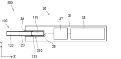
- 1 is a schematic diagram of an electrically heated flavor inhalation system according to an embodiment of the present invention.
- FIG. 2 is a diagram for explaining the configuration around a heating region in an electrically heated device.
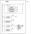
- FIG. 2 is a diagram for explaining a configuration of a control unit.
- 1 is a graph showing the evaluation results of the transfer of sensory components in an example.
- each element of the electrically heated flavor inhalation system is not limited to being arranged in the direction shown in the drawings.
- a flavor inhalation article (also simply referred to as a "flavor inhalation article”) is a flavor inhalation article having a flavor generating segment, a mouthpiece segment, and a lining sheet wrapping the flavor generating segment and the mouthpiece segment,
- the mouthpiece segment has at least one mouthpiece component segment, At least one of the mouthpiece constituent segments may have a first wrapper wound around its circumferential outer surface, and may further have a second wrapper wound inwardly of the first wrapper,
- the lining sheet has a base layer and a sensate-containing layer disposed on the outer surface side of the base layer, the sensate-containing layer containing a sensate and a carrier for carrying the sensate, At least one selected from the group consisting of the lining sheet, the first wrapper, and the second wrapper is oil resistant; It is a flavor inhalation article.
- the flavor inhalation article according to the present embodiment adopts a configuration in which a sensory component-containing layer containing a sensory component and a carrier that supports the sensory component is provided on the lining sheet in order to impart the sensory component to the lining sheet, so that migration of the sensory component is unlikely to occur compared to an embodiment in which the sensory component is added directly to the base material.
- the use mode of the flavor inhalation article according to the present embodiment is not particularly limited, and may be a non-combustion heating type flavor inhalation article or a cigarette (cigarette).
- An example of a non-combustion heating type flavor inhalation article is shown in FIG.
- the flavor inhalation article according to the present embodiment will be described with reference to FIG. 1, however, the present embodiment is not limited to this form.
- each embodiment and the like may be described using drawings, but the dimensions, materials, shapes, and relative positions of components described in the description of each embodiment and the drawings are merely examples.
- a flavor inhalation article containing a tobacco filler as a flavor source will be described as an example of a flavor inhalation article, but the flavor inhalation article may not contain a tobacco filler and may contain other flavor components.
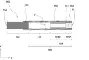
- the rod-shaped flavor inhalation article 100 shown in Fig. 1 is a flavor inhalation article having a mouthpiece segment 101, a flavor generating segment 102, and a lining sheet 103 around which the mouthpiece segment 101 and the flavor generating segment 102 are wound.
- the mouthpiece segment 101 includes a filter segment 104 consisting of a first filter segment 104A and a second filter segment 104B, and a cooling segment 105.
- the first filter segment 104A, the second filter segment 104B, the cooling segment 105, and the flavor generating segment 102 are provided coaxially adjacent to each other in this order in the axial direction (also referred to as the "long axis direction") of the flavor inhalation article 100, and an opening V is provided concentrically in the circumferential direction of the cooling segment 105.
- the opening V is usually a hole for promoting the inflow of air from the outside due to inhalation by a user, and the temperature of the components and air flowing in from the flavor generating segment 102 can be lowered by the inflow of this air.
- the first filter segment 104A and the second filter segment 104B each have a first wrapper 106 wound around the circumferential outer surface thereof.
- the first filter segment 104A further includes a second wrapper 107 wound on the inner side of the first wrapper 106, specifically, the second wrapper 107 disposed on the circumferential outer surface side of the first filter segment 104A, and a filter medium 108 disposed on the inner side of the second wrapper 107.
- the rod-shaped flavor inhalation article 100 shown in FIG. 2 is a flavor inhalation article having a mouthpiece segment 101, a flavor generating segment 102, and a lining sheet 103 around which the mouthpiece segment 101 and the flavor generating segment 102 are wound, and the mouthpiece segment 101 is a filter segment 104, which includes a filter medium 108 arranged inside the first wrapper 106.
- components generated by heating include flavor components derived from flavorings, nicotine and tar derived from tobacco leaves, and aerosol components derived from aerosol base materials.
- an aerosol base material is a base material for generating aerosols, and is not generally used in cigarettes.
- flavor components generated by burning the flavorings and tobacco leaves contained in the flavor generating segment 102 are usually carried into the user's mouth.
- reference numeral 151 denotes the mouth end of the flavor inhalation article 100 (mouthpiece segment 101).
- Reference numeral 152 denotes the tip of the flavor inhalation article 100 opposite the mouth end 151.
- the flavor generating segment 102 is disposed on the tip 152 side of the flavor inhalation article 100.
- each segment of the flavor inhalation article 100 is not limited to the embodiment shown in FIG. 1, but may be any general embodiment.
- the filter segment 104 includes two filter segments, a first filter segment 104A and a second filter segment 104B, but the embodiment may include only a single filter segment.
- the flavor inhalation article 100 preferably has a columnar shape that satisfies the aspect ratio defined as follows, which is 1 or more.
- Aspect ratio h/w w is the width of the base of the cylinder (in this specification, this is defined as the width of the base at the end (reference numeral 152) on the flavor generating segment 102 side), and h is the height, and it is preferable that h ⁇ w.
- the long axis direction is defined as the direction indicated by h. Therefore, even if w ⁇ h, the direction indicated by h will be referred to as the long axis direction for convenience.
- the shape of the base is not limited and may be a polygon, a rounded polygon, a circle, an ellipse, etc., and the width w is the diameter if the base is a circle, the major axis if the base is an ellipse, or the diameter of the circumscribing circle or the major axis of the circumscribing ellipse if the base is a polygon or a rounded polygon.
- the length h of the flavor inhalation article 100 in the longitudinal direction is not particularly limited, and is, for example, typically 40 mm or more, preferably 45 mm or more, and more preferably 50 mm or more, and is typically 100 mm or less, preferably 90 mm or less, and more preferably 80 mm or less.
- the width w of the bottom surface of the flavor inhalation article 100 is not particularly limited, and is, for example, usually 5 mm or more, preferably 5.5 mm or more, and usually 10 mm or less, preferably 9 mm or less, and more preferably 8 mm or less.
- the length ratio of the cooling segment 105 to the filter segment 104 in the longitudinal direction of the flavor inhalation article 100 is not particularly limited, but from the viewpoint of the delivery amount of the flavor component, it is usually 0.60 to 1.40:0.60 to 1.40, 0.80 to 1.20:0.80 to 1.20, preferably 0.85 to 1.15:0.85 to 1.15, more preferably 0.90 to 1.10:0.90 to 1.10, and even more preferably 0.95 to 1.05:0.95 to 1.05.
- the ratio of the lengths of the cooling segment 105 and the filter segment 104 within the above range, it is possible to achieve a balance between the cooling effect, the effect of suppressing losses due to adhesion of the generated steam and aerosol to the inner wall of the cooling segment, and the function of adjusting the air volume and flavor of the filter, thereby achieving an effect of presenting a good flavor.
- the cooling segment is made longer, the particulation of aerosols and the like is promoted, resulting in a good flavor, but if the cooling segment is too long, the passing substances will adhere to the inner wall.
- the airflow resistance in the longitudinal direction of each flavor inhalation article 100 is not particularly limited, but from the viewpoint of ease of inhalation, it is usually 10 mmH2O or more, preferably 20 mmH2O or more, and more preferably 30 mmH2O or more, and is usually 100 mmH2O or less, preferably 80 mmH2O or less, and more preferably 60 mmH2O or less.
- the airflow resistance is measured according to the ISO standard method (ISO6565:2015) using, for example, a filter airflow resistance measuring device manufactured by Cerulean Co., Ltd.
- the airflow resistance refers to the air pressure difference between the first end face and the second end face when air is flowed at a predetermined air flow rate (17.5 cc/min) from one end face (first end face) to the other end face (second end face) in a state where air does not pass through the side face of the flavor inhalation article 100.
- the unit is generally expressed in mmH 2 O. It is known that the relationship between the airflow resistance and the length of the flavor inhalation article 100 is proportional in the length range usually used (length 5 to 200 mm), and if the length is doubled, the airflow resistance of the flavor inhalation article 100 also doubles.
- At least one selected from the group consisting of the lining sheet 103, the first wrapper 106, and the second wrapper 107 (also referred to in this section as “lining sheet 103, etc.") has oil resistance.
- oil resistance means that when oil is adhered, it does not easily soak in, spread, or leak to the opposite surface.
- the method of imparting oil resistance to the lining sheet 103 and the like is not particularly limited.
- a method using a material having oil resistance can be mentioned, and specifically, a method of providing a layer containing a material having oil resistance, or a method of incorporating a material having oil resistance into a layer such as a substrate can be mentioned.
- the material having oil resistance can be incorporated into the substrate layer, or a layer containing a material having oil resistance can be provided as a layer other than the substrate layer and the sensory component-containing layer.
- the oil-resistant material is not particularly limited, but examples thereof include starch, nitrocellulose lacquer, ethylcellulose lacquer, acetylcellulose lacquer, paraffin, polyolefin, polystyrene, silicon, resin, acrylic resin, fluororesin, etc., and from the viewpoint of the influence on the smoking taste, starch, nitrocellulose lacquer, or fluororesin is preferable. Glassine paper and non-permeable paper, which have reduced gaps between the fibers of the paper, also have oil resistance.
- the content of the oil-resistant material per area in the planar direction of the lining sheet 103 is not particularly limited, but is usually 0.01 gsm or more, preferably 0.05 gsm or more, more preferably 0.1 gsm or more, and even more preferably 0.2 gsm or more, and is usually 5 gsm or less, preferably 3 gsm or less, and more preferably 2 gsm or less. If the content is equal to or greater than the lower limit of the above range, oil resistance can be uniformly imparted. Also, if the content is equal to or less than the upper limit of the above range, the effect on the winding suitability during winding can be suppressed.
- the degree of oil resistance of the lining sheet 103 etc. is not particularly limited, but the kit value that can be used as an evaluation parameter of oil resistance is preferably 2 or more, more preferably 3 or more, even more preferably 5.5 or more, and even more preferably 6 or more.
- the kit value can be increased, for example, by increasing the basis weight of the oil-resistant layer (increasing the thickness) or increasing the amount of the oil-resistant material. Note that the higher the kit value, the better the oil resistance, and there is no need to set an upper limit.
- the above kit value can be measured according to JAPAN TAPPI Paper and Pulp Test Method No. 41:2000 "Paper and Paperboard - Oil Repellency Test Method - Kit Method".
- This method specifies that five or more sheets having a size of at least 50 mm x 50 mm should be prepared as the evaluation object.
- the arranged lining sheets 103 etc. may overlap each other partially to the extent that the width of the overlapping portion is 1 mm or less.
- the test liquid is dropped onto the lining sheet 103 etc. having the largest area among the arranged lining sheets 103 etc.
- the flavor inhalation article 100 has a lining sheet 103 around which a flavor generating segment 102 and a mouthpiece segment 101 are wrapped.
- the lining sheet 103 has a base layer and a sensory component-containing layer arranged on the outer surface side of the base layer, and the sensory component-containing layer is not particularly limited as long as it contains a sensory component and a carrier for carrying the sensory component, and may have layers other than the base layer and the sensory component-containing layer.
- the basis weight of the lining sheet 103 is not particularly limited, but is usually 10 gsm or more and 120 gsm or less, preferably 25 gsm or more and 80 gsm or less, and more preferably 30 gsm or more and 60 gsm or less. If the basis weight is equal to or more than the lower limit of the above range, each segment can be firmly bonded. If the basis weight is equal to or less than the upper limit of the above range, high-speed winding is possible.
- the basis weight of the lining sheet 103 is calculated based on the weight of the substrate layer and the sensory component-containing layer described below, and if present, is calculated based on the weight of the layers that are optionally provided, such as the anchor layer, color layer, cover layer, and lip release layer, added to the weight.
- the thickness of the lining sheet 103 is not particularly limited, but is usually 10 ⁇ m or more and 120 ⁇ m or less, preferably 20 ⁇ m or more and 80 ⁇ m or less, and more preferably 35 ⁇ m or more and 55 ⁇ m or less.
- the air permeability of the lining sheet 103 is not particularly limited, but is usually 0 Coresta units or more and 30,000 Coresta units or less, and preferably more than 0 Coresta units and 10,000 Coresta units or less. When openings are provided on the lining sheet 103, it is preferably 0 Coresta units or more and 15 Coresta units or less, and more preferably 0 Coresta units.
- the air permeability is a value measured in accordance with ISO 2965:2009, and is expressed as the flow rate (cm 3 ) of gas passing through an area of 1 cm 2 per minute when the differential pressure between both sides of the paper is 1 kPa.
- 1 Coresta unit (1 Coresta unit, 1 C.U.) is cm 3 /(min ⁇ cm 2 ) under 1 kPa.
- the lining sheet 103 is oil-resistant, it is preferable that the sensory component-containing layer or a layer provided on the inner peripheral side of the sensory component-containing layer is oil-resistant. If neither the first wrapper 106 nor the second wrapper 107 is oil-resistant, it is necessary that the sensory component-containing layer or a layer provided on the inner peripheral side of the sensory component-containing layer is oil-resistant.
- the embodiment of the substrate layer is not particularly limited, and the embodiment used as a lining sheet in known cigarettes or non-combustion heating type flavor inhalation articles can be applied.
- paper made of general plant fiber (pulp), a sheet using polymer-based chemical fiber (polypropylene, polyethylene, nylon, etc.), a polymer-based sheet, metal foil, etc., or a composite material combining these can be used.
- a composite material in which a polymer-based sheet is bonded to a paper substrate can be used.
- paper is used as the substrate layer will be described, but it can also be applied to the case where a material other than paper is used within the applicable range.
- the paper may be, for example, one containing pulp as a main component.
- the pulp may be made from wood pulp such as softwood pulp or hardwood pulp, or may be made by mixing non-wood pulp, such as flax pulp, hemp pulp, sisal pulp, or esparto, which is generally used for wrapping paper for flavor inhalation products. These pulps may be used alone or in combination of multiple types in any ratio.
- the paper may consist of one sheet, but may also consist of multiple sheets or more.
- As the form of pulp chemical pulp produced by a kraft cooking method, an acidic/neutral/alkaline sulfite cooking method, a soda salt cooking method, or the like, ground pulp, chemi-ground pulp, thermomechanical pulp, or the like can be used.
- the paper may contain fillers, such as metal carbonates such as calcium carbonate or magnesium carbonate, metal oxides such as titanium oxide, titanium dioxide or aluminum oxide, metal sulfates such as barium sulfate or calcium sulfate, metal sulfides such as zinc sulfide, quartz, kaolin, talc, diatomaceous earth or gypsum, and it is particularly preferable for the paper to contain calcium carbonate from the viewpoints of improving whiteness and opacity, and increasing the heating rate.
- these fillers may be used alone or in combination of two or more types.
- the paper may contain a water resistance improver to improve water resistance.
- water resistance improvers include wet strength agents (WS agents) and sizing agents.
- wet strength agents include urea formaldehyde resin, melamine formaldehyde resin, and polyamide epichlorohydrin (PAE).
- PAE polyamide epichlorohydrin
- sizing agents include rosin soap, alkyl ketene dimer (AKD), alkenyl succinic anhydride (ASA), and highly saponified polyvinyl alcohol with a saponification degree of 90% or more.
- the basis weight of the base layer is not particularly limited, but is usually 10 gsm or more and 100 gsm or less, preferably 20 gsm or more and 70 gsm or less, and more preferably 30 gsm or more and 50 gsm or less.
- the air permeability of the base layer is not particularly limited, but is usually 0 Coresta units or more and 30,000 Coresta units or less, and preferably more than 0 Coresta units and 10,000 Coresta units or less.
- the air permeability of the base layer is a value measured in accordance with ISO 2965:2009, and is expressed as the flow rate (cm 3 ) of gas passing through an area of 1 cm 2 per minute when the differential pressure between both sides of the paper is 1 kPa.
- 1 Coresta unit (1 Coresta unit, 1 C.U.) is cm 3 /(min ⁇ cm 2 ) under 1 kPa.
- the shape of the substrate layer is not particularly limited and can be, for example, square or rectangular.
- the substrate layer may be produced by a known method or a combination of known methods, or a commercially available product may be used.
- a method can be mentioned in which the texture is adjusted and made uniform during the papermaking process using pulp on a Fourdrinier paper machine, a cylinder paper machine, or a combined cylinder and short-distance paper machine.
- the embodiment of the sensory ingredient-containing layer is not particularly limited as long as it contains a sensory ingredient and a carrier for carrying the sensory ingredient.
- the type of sensation is not particularly limited as long as it is a sensation that the user can feel on the lips, tongue, or in the mouth, and examples include skin sensations such as coldness and spiciness, and tastes such as sourness, bitterness, or sweetness.
- the sensory component is not particularly limited in type as long as it has an effect on perception, and may be, for example, at least one component selected from the group consisting of cooling components, sour components, bitter components, bitterness suppressing components, sweet components, and spicy components.
- Specific components include, for example, the components listed below, but any component generally used as a sensory component may be used.
- the sensory component may be used alone or in combination of two or more types.
- cooling sensation components include 3-l-menthoxypropane-1,2-diol, N-alkyl-p-menthane-3-carboxamide, 3-l-menthoxy-2-methylpropane-1,2-diol, menthol, menthone, camphor, pulegol, isopulegol, cineole, peppermint oil, peppermint oil, spearmint oil, eucalyptus oil, p-menthane-3,8-diol, 2-l-menthoxyethan-1-ol, 3-l-menthoxypropan-1-ol, and the like.
- menthyl 4-l-menthoxybutan-1-ol, menthyl 3-hydroxybutanoate, menthyl lactate, menthone glycerin ketal, 2-(2-l-menthyloxyethyl)ethanol, menthyl glyoxylate, 1-(2-hydroxy-4-methylcyclohexyl)ethanone, N-methyl-2,2-isopropyl, methyl-3-methylbutanamide, menthyl 2-pyrrolidone-5-carboxylate, or N-(ethoxycarbonylmethyl)-3-p-menthanecarboxamide.
- sour components include citric acid, tartaric acid, malic acid, ascorbic acid, adipic acid, sodium citrate, glucono delta lactone, gluconic acid, succinic acid, monosodium succinate (crystal), anhydrous sodium acetate, DL-tartaric acid, L-tartaric acid, sodium DL-tartrate, sodium L-tartrate, lactic acid, sodium lactate, glacial acetic acid, fumaric acid, monosodium fumarate, DL-malic acid, sodium DL-malate, and phosphoric acid.
- bitter components examples include caffeine, coffee extract, green tea extract, black tea extract, quinine, quinine hydrochloride, denatonium benzoate, theobromine, cacao extract, limonin, naringin, hesperidin, glycosyltransferase vitamin P, tannin, tryptophan, phenylalanine, tyrosine, arginine, valine, leucine, isoleucine, proline, isoflavone, rutin, wormwood extract, Swertia japonica extract, hop extract, humulone, isohumulone, or a mixture thereof.
- bitterness suppressing components include sodium chloride, sodium gluconate, sodium acetate, erythritol, sugar-added vitamin P, thaumatin, sodium succinate, sodium tartrate, sodium citrate, sodium malate, sodium glutamate, sodium phosphate, and phospholipids.
- sweetening components include glucose, fructose, maltose, sucrose, oligosaccharides, trehalose, maltose, isomaltulose, xylitol, sorbitol, erythritol, aspartame, acesulfame potassium, licorice, saccharin, and stevia.
- pungent components include extracts of chili pepper, ginger, mustard, Japanese pepper, pepper, or garlic, capsaicin, zingerone, shogaol allyl isothiocyanate, oxybenzyl isothiocyanate, sanshool, piperine, chavicine, and allyl sulfide.
- the content of the sensory ingredient in the sensory ingredient-containing layer is not particularly limited, but is usually 0.1 gsm or more, preferably 0.3 gsm or more, more preferably 0.5 gsm or more, even more preferably 0.7 gsm or more, and 1.7 gsm or less, preferably 1.3 gsm or less, more preferably 1.0 gsm or less, and even more preferably 0.8 gsm or less. If the content is equal to or greater than the lower limit of the above range, sufficient sensory ingredients can be imparted to the user. Also, if the content is equal to or less than the upper limit of the above range, the effect on the proper winding during winding can be suppressed.
- the type of carrier is not particularly limited as long as it can carry the sensory component. Examples include water-soluble lacquer, hydrophobic lacquer, nitrocellulose, and ethyl cellulose. From the viewpoint of being able to stably carry the sensory component, nitrocellulose or ethyl cellulose is preferred.
- One type of carrier may be used alone, or two or more types may be used in combination.
- the content of the carrier in the sensory component-containing layer is not particularly limited, but is usually 10% by mass or more, preferably 20% by mass or more, and more preferably 30% by mass or more, and is usually 95% by mass or less, preferably 90% by mass or less, more preferably 75% by mass or less, and even more preferably 60% by mass or less. If the content is equal to or greater than the lower limit of the above range, the sensory component can be sufficiently supported. Also, if the content is equal to or less than the upper limit of the above range, the effect on the proper winding during winding can be suppressed.
- the method for providing a sensory ingredient-containing layer as part of the lining sheet 103 is not particularly limited, and examples include a method in which the sensory ingredient and a carrier are mixed and the mixture obtained is applied to another layer such as a base layer, or a method in which the mixture is formed into a film and adhered to another layer such as a base layer.
- a solvent may be used. In this case, after the coating or film formation, the mixture is naturally dried or heated to remove the solvent.
- the region where the sensory component-containing layer is provided is not particularly limited, and may be the entire region of the lining sheet 103 or a part of the region.
- the sensory component-containing layer is present in at least a part of the lining sheet 103 when viewed from the thickness direction of the lining sheet 103, it is preferable that at least a part of the sensory component-containing layer is present in a region up to 15 mm from the end of the lining sheet 103 on the mouth end side, and further, the length from the end is more preferably up to 12 mm, and even more preferably up to 10 mm from the end.
- the sensory component-containing layer only needs to be included in at least a part of the region from the end to the above, and may be included over the entire region or only a part of the region.
- the lining sheet 103 is configured so that the sensory component-containing layer is not present in the area up to 1 mm from the end on the mouth end side. By configuring it in this way, it becomes easier to provide the user with sufficient sensory components while suppressing raw material costs.
- the lining sheet 103 may further have an anchor layer disposed between the base layer and the sensory component-containing layer, from the viewpoint of making it easier to suppress the transfer of sensory components and, if ink is used, improving the adhesion of the ink.
- the type of component contained in the anchor layer is not particularly limited as long as it can suppress peeling of the sensory component-containing layer from the lining sheet 103, and examples thereof include at least one component selected from the group consisting of hydrophobic lacquer, nitrocellulose, ethyl cellulose, etc. These components may be used alone or in combination of two or more.
- the anchor layer may contain these components in part, or may consist of only these components.
- the amount of the anchor layer is not particularly limited, and is, for example, usually 0.1 gsm or more, preferably 0.2 gsm or more, more preferably 0.3 gsm or more, and usually 1.0 gsm or less, preferably 0.8 gsm or less, and even more preferably 0.6 gsm or less. If the amount of the anchor layer is equal to or greater than the lower limit of the above range, peeling of the sensory component-containing layer can be suppressed. Also, if the amount of the anchor layer is equal to or less than the upper limit of the above range, the effect on the proper winding during winding can be suppressed.
- the method for providing an anchor layer as part of the lining sheet 103 is not particularly limited, and examples thereof include a coating method or a method of adhering after film formation, similar to the method for providing the sensory ingredient-containing layer described above.
- the region where the anchor layer is provided is not particularly limited, and may be the entire region of the lining sheet 103 or a part of the region.
- the anchor layer is provided only in the region downstream of the surface where the flavor generating segment and the mouthpiece segment contact each other. More preferably, the anchor layer is provided only in the region 10 mm or more downstream of the surface where the flavor generating segment and the mouthpiece segment contact each other.
- the lining sheet 103 may further have a colored layer in order to achieve the desired appearance, and in particular, when the above-mentioned anchor layer is applied, it is preferable to have a colored layer disposed between the sensory ingredient-containing layer and the anchor layer.
- the type of components contained in the colored layer is not particularly limited as long as it can be colored, and coloring components such as dyes and pigments of various colors can be used.
- the colored layer may further contain hydrophobic lacquer varnish, nitrocellulose, ethyl cellulose, etc. In this case, the colored layer may have the colored components dispersed over the entire surface of the colored layer, or may be partially dispersed. In addition, the colored layer may have the colored components disposed on the inner surface of the colored layer.
- the method for providing a colored layer as part of the lining sheet 103 includes a coating method or a method of adhering after film formation, similar to the method for providing the sensory component-containing layer described above.
- the lining sheet 103 may further have a cover layer placed on the outer surface of the sensory ingredient-containing layer, from the viewpoint of suppressing physical friction during manufacturing and the volatilization of ingredients contained in the inner layer during storage.
- the type of material for the cover layer is not particularly limited as long as it can suppress deterioration due to influences from the surroundings, and examples thereof include at least one material selected from the group consisting of wax, resin, paper, film, water-soluble polymer, hydrophobic polymer, hydrophobic lacquer varnish, nitrocellulose, ethyl cellulose, etc. These materials may be used alone or in combination of two or more.
- the method for providing the cover layer as part of the lining sheet 103 is not particularly limited, and examples thereof include a coating method or a method of forming a film and then adhering it, similar to the method for providing the sensory ingredient-containing layer described above.
- the region where the cover layer is provided is not particularly limited, and may be the entire region of the lining sheet 103 or a part of the region.
- the cover layer is provided only in the region downstream of the surface where the flavor generating segment and the mouthpiece segment contact each other. More preferably, the cover layer is provided only in the region 10 mm or more downstream of the surface where the flavor generating segment and the mouthpiece segment contact each other. Even more preferably, the cover layer is provided so as to cover the entire sensory component-containing layer. Furthermore, the cover layer is provided so as not to exceed the region where the anchor layer is located.
- the lining sheet 103 may be textured in at least a portion of the area in which the sensory component-containing layer is present, when viewed through its thickness, from the viewpoint of reducing the area of physical contact with external substances and thereby inhibiting the loss of sensory components, etc., and from the viewpoint of achieving a desired appearance and feel.
- the method for texture processing is not particularly limited, and examples thereof include embossing and coating various layers partially to a large thickness.
- the ratio of the textured area to the area of the lining sheet 103 is not particularly limited.
- the texture may be applied to the entire surface of the lining sheet 103, or may be applied partially. By applying texture to the lining sheet, the area of contact between the lining sheet 103 of one flavor inhalation article 100 and the lining sheet of another flavor inhalation article 100 when the flavor inhalation article 100 is packaged in a small box can be reduced.
- the texture may also be applied to an area up to 15 mm from the end of the lining sheet 103 on the mouth end side. When a user holds the flavor inhalation article 100 in his/her mouth, the texture comes into contact with the user's lips, providing a new skin sensation.
- the lining sheet 103 may further have a lip release layer disposed on the outer surface side of the sensory component-containing layer in order to prevent the user's lips from adhering to the flavor inhalation article 100.
- the lip release layer may be treated as a type of the above-mentioned cover layer.
- the lip release layer includes or is made of a lip release material.
- the lip release material refers to a material configured to assist in the easy separation of the contact between the lips and the lining sheet 103 without substantial adhesion when the user holds the flavor inhalation article 100 in the mouth.
- the lip release material may include, for example, nitrocellulose, ethyl cellulose, or methyl cellulose.
- the outer surface of the lining sheet 103 may be coated with the lip release material by applying an ethyl cellulose-based or methyl cellulose-based ink to the outer surface of the lining sheet 103.
- the lip release material is usually placed at least in a predetermined mouthpiece area that comes into contact with the lips of a user when the user holds the flavor inhalation article 100 in the mouth.
- the lip release material placement area R1 of the outer surface of the lining sheet 103 that is covered with the lip release material can be defined as the area located between the mouthpiece end 151 of the filter segment 104 and the aperture V.
- the flavor inhalation article 100 has a mouthpiece segment 101.
- the configuration of the mouthpiece segment 101 is not particularly limited as long as it has at least one mouthpiece constituent segment, and at least one of the mouthpiece constituent segments has a first wrapper wound around its circumferential outer surface, and further has a second wrapper wound on the inner side of the first wrapper.
- Mouthpiece constituent segments that may be included in the mouthpiece segment 101 may be segments that are generally included in the mouthpieces of non-combustion heating type flavor inhalation articles or cigarettes, and examples thereof include a filter segment 104 or a cooling segment 105. The filter segment 104 and the cooling segment 105 will be described in detail below.
- At least one of the mouthpiece constituent segments preferably includes a filler (mouthpiece constituent segment filler).
- a filler mouthpiece constituent segment filler
- the form of the mouthpiece component segment containing the above-mentioned filling is not particularly limited, and examples include a segment containing a filter medium, which will be described below as an example of filter segment 104, or a center hole segment, and examples include forms in which materials such as cellulose acetate fiber, natural pulp fiber, or paper are used as the material for the filter medium or the material constituting the center hole segment.
- the filler does not need to contain cellulose acetate fibers, since this makes it easier to prevent the sensory components in the sensory component-containing layer of the lining sheet 103 from migrating to the filler.
- the filler may contain natural pulp fibers, from the viewpoint of easily preventing the sensory components in the sensory component-containing layer in the above-mentioned lining sheet 103 from migrating to the filler.
- the form of the mouthpiece constituent segment containing the above-mentioned filling is not particularly limited, and examples include a segment containing a filter medium, which will be described below as an example of filter segment 104, or a center hole segment, and examples include a form in which a material containing natural pulp fibers, particularly paper, is used as the material for the filter medium or the material constituting the center hole segment.
- the mouthpiece segment 101 may have a mouthpiece component segment that does not contain a filler, from the viewpoint of easily preventing the sensory components in the sensory component-containing layer in the inning sheet 103 from migrating to the filler.
- the form of the mouthpiece segment that does not contain a filler is not particularly limited, and an example thereof is a paper tube, which will be described later as an example of the cooling segment 105.
- the filter segment 104 is not particularly limited in its form as long as it has a function as a general filter, and may be composed of a single segment or two or more segments. When the filter segment 104 includes two or more segments, it may be configured to include a first filter segment 104A and a second filter segment 104B, as shown in FIG. 1. Examples of general functions of a filter include adjusting the amount of air mixed when inhaling an aerosol, reducing flavor, and reducing nicotine and tar, but it is not necessary to have all of these functions.
- one of the important functions is to suppress the filtration function while preventing the tobacco filler from falling and to suppress the scattering of aggregated droplets into the oral cavity.
- the filter segment 104 may be, for example, a tow made of synthetic fibers (also simply referred to as "tow"), or a material such as paper processed into a cylindrical shape.
- the shape of the filter segment 104 is not particularly limited, and any known shape can be adopted.
- the filter segment 104 can be cylindrical.
- the filter segment 104 may have a section such as a cavity (such as a center hole) or a recess whose circumferential cross section is hollow (hollow), as shown in the second filter segment 104B in Fig. 1.
- the center hole segment having a center hole is usually arranged upstream of a segment having a filter medium (e.g., an acetate filter segment), and is preferably arranged adjacent to the upstream cooling segment. According to such an embodiment, unnecessary loss of the generated aerosol can be prevented, and the appearance of the flavor inhalation article 100 can be improved.
- a filter medium e.g., an acetate filter segment
- the cross-sectional shape of the filter segment 104 in the circumferential direction is substantially circular, and the diameter of the circle can be appropriately changed according to the size of the product, but is usually 4.0 mm or more and 9.0 mm or less, preferably 4.5 mm or more and 8.5 mm or less, and more preferably 5.0 mm or more and 8.0 mm or less.
- the cross section is not circular, the above diameter is applied to a circle having the same area as the cross section.
- the circumferential length of the circumferential cross-sectional shape of the filter segment 104 can be appropriately changed according to the size of the product, but is typically 14.0 mm or more and 27.0 mm or less, preferably 15.0 mm or more and 26.0 mm or less, and more preferably 16.0 mm or more and 25.0 mm or less.
- the overall axial length of the filter segment 104 can be appropriately changed according to the size of the product, but is usually 5 mm or more and 35 mm or less, and preferably 10.0 mm or more and 30.0 mm or less.
- the shape and dimensions of the filter material can be adjusted as appropriate so that the shape and dimensions of the filter segment 104 are within the above ranges.
- the airflow resistance per 120 mm of axial length of the filter segment 104 is not particularly limited, but is usually 40 mmH2O or more and 300 mmH2O or less, preferably 70 mmH2O or more and 280 mmH2O or less, and more preferably 90 mmH2O or more and 260 mmH2O or less.
- the airflow resistance of the filter segment 104 can be measured by a method similar to the method for measuring the airflow resistance of the flavor inhalation article 100 described above.
- the filter segment 104 may be a segment including a filter medium 108, as shown in the first filter segment 104A in FIG. 1.
- the density of the filter medium 108 is not particularly limited, but is usually 0.10 g/cm 3 or more and 0.25 g/cm 3 or less, preferably 0.11 g/cm 3 or more and 0.24 g/cm 3 or less, and more preferably 0.12 g/cm 3 or more and 0.23 g/cm 3 or less.
- this density does not include the additive release container.
- the form of the filter medium 108 is not particularly limited, and any known form may be adopted, such as natural pulp fibers or cellulose acetate tow (cellulose acetate fibers) processed into a cylindrical shape.
- the single thread fineness and total fineness of these fibers are not particularly limited, but in the case of a mouthpiece member with a circumference of 22 mm, the single thread fineness is preferably 5 to 20 g/9000 m and the total fineness is preferably 12,000 to 30,000 g/9000 m.
- Examples of the cross-sectional shape of the fiber include circular, elliptical, Y-shaped, I-shaped, and R-shaped.
- the cellulose acetate long fibers may be solidified with a plasticizer (triacetin).
- triacetin may be added in an amount of 5% by weight or more and 10% by weight or less relative to the weight of the cellulose acetate tow.
- other alternative filters such as a paper filter filled with sheet-like pulp paper as a filter medium can be used.
- the filter segment 104 can be manufactured by a known method. For example, as shown in the first filter segment 104A in FIG. 1, when synthetic fibers such as cellulose acetate tow are used as the material for the filter medium 108, the filter segment 104 can be manufactured by spinning a polymer solution containing a polymer and a solvent and then shrinking the spinned polymer solution. For example, the method described in WO 2013/067511 can be used as the method.
- the filter medium 108 may also contain ingredients such as flavorings in addition to the additive release container described later, and examples of the flavorings include menthol, spearmint, peppermint, fenugreek, clove, and medium-chain triglycerides (MCTs).Flavors similar to those contained in the flavor generating segment 102 described later may also be used, with menthol being preferred.One of these ingredients may be used alone, or two or more of them may be used in any type and ratio. By adding the flavoring to the filter medium 108, the amount of flavoring delivered during use is increased compared to the conventional technology in which the flavoring is added only to the tobacco filling in the flavor generating segment 102.
- MCTs medium-chain triglycerides
- the degree of increase in the amount of flavoring delivered is further increased depending on the position of the opening V provided in the cooling segment 105.
- There is no particular limitation on the method of adding the flavoring to the filter medium 108 and it is sufficient to add the flavoring so that it is dispersed approximately uniformly in the filter medium to which the flavoring is to be added.
- the amount of flavoring added can be 10 to 100 volume % of the filter medium 108.
- the flavoring may be added to the filter medium 108 in advance before the filter segment 104 is constructed, or it may be added after the filter segment 104 is constructed.
- Activated carbon may be added to the filter medium 108.
- the amount of activated carbon added to the filter medium 108 may be 15.0 m 2 /cm 2 or more and 80.0 m 2 /cm 2 or less as a value of the specific surface area of activated carbon ⁇ the weight of activated carbon / the cross-sectional area of the filter medium perpendicular to the airflow direction in one flavor inhalation article 100.
- the above-mentioned "specific surface area of activated carbon ⁇ the weight of activated carbon / the cross-sectional area of the filter medium perpendicular to the airflow direction" may be expressed as "the surface area of activated carbon per unit cross-sectional area" for convenience.
- This surface area of activated carbon per unit cross-sectional area can be calculated based on the specific surface area of activated carbon added to the filter medium of one flavor inhalation article 100, the weight of the added activated carbon, and the cross-sectional area of the filter medium. Note that activated carbon may not be uniformly dispersed in the filter medium to which it is added, and it is not required that the above range is satisfied in all cross-sections of the filter medium (cross-sections perpendicular to the airflow direction).
- the surface area of the activated carbon per unit cross-sectional area is more preferably 17.0 m 2 /cm 2 or more, and even more preferably 35.0 m 2 /cm 2 or more. On the other hand, it is more preferably 77.0 m 2 /cm 2 or less, and even more preferably 73.0 m 2 /cm 2 or less.
- the surface area of the activated carbon per unit cross-sectional area can be adjusted, for example, by adjusting the specific surface area of the activated carbon and its added amount, and the cross-sectional area of the filter medium in the direction perpendicular to the aeration direction.
- the calculation of the surface area of the activated carbon per unit cross-sectional area is calculated based on the filter medium to which the activated carbon is added.
- the filter segment 104 is composed of a plurality of filter mediums, the cross-sectional area and length of only the filter medium to which the activated carbon is added are used as the basis.
- activated carbon examples include those made from wood, bamboo, coconut shells, walnut shells, or coal.
- Activated carbon may have a BET specific surface area of 1100 m 2 /g or more and 1600 m 2 /g or less, preferably 1200 m 2 /g or more and 1500 m 2 /g or less, and more preferably 1250 m 2 /g or more and 1380 m 2 /g or less.
- the BET specific surface area can be determined by a nitrogen gas adsorption method (BET multipoint method).
- Activated carbon may have a pore volume of 400 ⁇ L/g or more and 800 ⁇ L/g or less, more preferably 500 ⁇ L/g or more and 750 ⁇ L/g or less, and more preferably 600 ⁇ L/g or more and 700 ⁇ L/g or less.
- Pore volume can be calculated from the maximum adsorption amount obtained by using nitrogen gas adsorption method.
- the amount of activated carbon added per unit length of the filter material in the direction of airflow is preferably 5mg/cm or more and 50mg/cm or less, more preferably 8mg/cm or more and 40mg/cm or less, and even more preferably 10mg/cm or more and 35mg/cm or less.By making the specific surface area of activated carbon and the amount of activated carbon added within the above range, the surface area of activated carbon per unit cross-sectional area can be adjusted to a desired one.
- the activated carbon particles preferably have a cumulative 10% by volume particle diameter (particle diameter D10) of 250 ⁇ m or more and 1200 ⁇ m or less.
- the activated carbon particles preferably have a cumulative 50% by volume particle diameter (particle diameter D50) of 350 ⁇ m or more and 1500 ⁇ m or less.
- the particle diameters D10 and D50 can be measured by a laser diffraction scattering method.
- An example of an apparatus suitable for this measurement is the laser diffraction/scattering type particle size distribution measuring apparatus "LA-950" manufactured by Horiba, Ltd.
- the powder is poured into the cell of this apparatus together with pure water, and the particle diameter is detected based on the light scattering information of the particles.
- the measurement conditions using the above measuring device are as follows.
- Measurement mode Manual flow-mode cell
- Measurement dispersion medium Ion-exchanged water Dispersion method: Measured after 1 minute of ultrasonic irradiation Refractive index: 1.92-0.00i (sample refractive index) / 1.33-0.00i (dispersion medium refractive index) Number of measurements: Measure twice using different samples
- the filter medium 108 may include a crushable additive release container (e.g., a capsule) that includes a crushable shell such as gelatin.
- the capsule also referred to in the art as an "additive release container”
- a crushable additive release container that includes a crushable shell such as gelatin.
- the capsule when the capsule is broken by a tobacco product user before, during, or after use, it releases a liquid or substance (usually a flavoring) contained in the capsule, which is then transferred to tobacco smoke during use of the tobacco product and to the surrounding environment after use.
- the form of the capsule is not particularly limited, and may be, for example, a frangible capsule, and its shape is preferably a sphere.
- the additive contained in the capsule may include any of the additives described above, and is preferably, in particular, a flavoring or activated carbon.
- one or more materials that help filter smoke may be added as the additive.
- the form of the additive is not particularly limited, and is usually a liquid or solid.
- the use of capsules containing additives is well known in the art.
- Frangible capsules and methods for producing them are well known in the art.
- the flavoring may be, for example, menthol, spearmint, peppermint, fenugreek, or clove, medium chain triglycerides (MCT), etc.
- the flavoring may be menthol, or menthol, etc., or a combination thereof.
- the filter segment 104 may include a second wrapper 107 wrapped with the filter material described above, as shown in the first filter segment 104A of FIG. 1, for increased strength and structural rigidity.
- the second wrapper 107 may include one or more rows of adhesive-containing seams without any particular limitations.
- the adhesive may include a hot melt adhesive, and the hot melt adhesive may include polyvinyl alcohol.
- first wrapper 106 that wraps these two or more segments together, as shown in the first filter segment 104A in Fig. 1.
- first wrapper 106 the first wrapper in Fig. 1 that wraps two or more segments together
- the wrapper that is wrapped around the outer circumferential surface of one segment the second wrapper in Fig. 1
- FIG. 3 reference numerals other than the first wrapper 106 and the second wrapper 107 are omitted.
- the wrapper wound around the circumferential outer surfaces of the first filter segment 104A and the second filter segment 104B is the first wrapper 106, and the wrapper disposed inside thereof and wound around the circumferential outer surface of the first filter segment 104A is the second wrapper 107.
- the wrapper wound around the circumferential outer surfaces of the first filter segment 104A and the second filter segment 104B is the first wrapper 106, and the wrapper arranged inside thereof and wound around the circumferential outer surface of the first filter segment 104A and the circumferential outer surface of the second filter segment 104B is the second wrapper 107.
- the wrapper wound around the circumferential outer surfaces of the first filter segment 104A and the second filter segment 104B is the first wrapper 106, and there is no wrapper disposed on the inside thereof, and therefore there is no second wrapper 107.
- the wrapper wound around the circumferential outer surface of the first filter segment 104A is the first wrapper 106, and there is no wrapper disposed on the inside thereof, and therefore there is no second wrapper 107.
- the materials for the first wrapper 106 and the second wrapper 107 are not particularly limited and may be any known material, and may contain fillers such as calcium carbonate.
- the thickness of the first wrapper etc. is not particularly limited, and is usually 20 ⁇ m or more and 140 ⁇ m or less, preferably 30 ⁇ m or more and 130 ⁇ m or less, and more preferably 30 ⁇ m or more and 120 ⁇ m or less.
- the basis weight of the first wrapper etc. is not particularly limited and is usually 20 gsm or more and 100 gsm or less, preferably 22 gsm or more and 95 gsm or less, and more preferably 23 gsm or more and 90 gsm or less.
- the first wrapper etc. may be coated or uncoated, but from the standpoint of imparting functions other than strength and structural rigidity, it is preferable for it to be coated with a desired material.
- the first wrapper 106 and the second wrapper 107 may be of different materials, thicknesses, basis weights, and breathability.
- first wrapper 106 and the second wrapper 107 When at least one selected from the group consisting of the first wrapper 106 and the second wrapper 107 is oil resistant, either wrapper may be oil resistant, or both wrappers may be oil resistant. Furthermore, when comparing the first wrapper 106 and the second wrapper 107, from the viewpoint of easily preventing the sensory components in the sensory component-containing layer from migrating into the interior of the mouthpiece segment, it is preferable that the first wrapper be oil-resistant. In particular, when the mouthpiece segment has two or more mouthpiece constituent segments and at least two of the mouthpiece constituent segments are wrapped with the first wrapper, it is preferable that the first wrapper be oil-resistant.
- the center hole segment When a center hole segment (second filter segment 104B in FIG. 1) is used as the filter segment 104, the center hole segment may be composed of a filling layer having one or more hollow portions and a wrapper (first wrapper or second wrapper) wound around the outer peripheral surface of the filling layer.
- the center hole segment has the function of adjusting the length of the flavor inhalation article in the longitudinal direction (Z direction) while increasing the strength of the mouthpiece segment.
- the filling layer can be, for example, a rod with an inner diameter of ⁇ 1.0 mm or more and ⁇ 5.0 mm or less, which is densely packed with cellulose acetate fibers and hardened by adding a plasticizer containing triacetin in an amount of 6 mass% or more and 20 mass% or less relative to the mass of cellulose acetate. Since the filling layer has a high fiber packing density, air and aerosol flow only through the hollow portions during inhalation and hardly flow inside the filling layer. Since the filling layer inside the center hole segment is a fiber packed layer, the touch from the outside during use is less likely to cause discomfort to the user. Alternatively, the center hole segment may not have a wrapper and its shape may be maintained by thermoforming.
- the cooling segment 105 is one type of constituent segment of the mouthpiece segment 101, and is sandwiched adjacent to the flavor generating segment 102 and the filter segment 104. It is usually a rod-shaped member having a cavity in which the circumferential cross section of a cylinder or the like is hollow (hollow), for example, a cardboard tube.
- the cooling segment 105 may be provided with openings V (also referred to in the art as "ventilation filters (Vf)”) in the circumferential direction and concentrically therewith.
- the flavor generating segment 102 When an aerosol base material is used in the flavor generating segment 102, the flavor generating segment 102 is heated, and the vapor containing the aerosol base material and tobacco flavor components is liquefied by a decrease in temperature in the hollow portion, and particularly when the opening V is provided, the vapor is liquefied by a decrease in temperature due to contact with air from the outside, thereby accelerating the generation of the aerosol.
- the opening V will be described in detail below.
- the number of the openings V in the cooling segment 105 is not particularly limited, and a plurality of openings V may be arranged at regular intervals in the circumferential direction of the cooling segment 105.
- the cooling effect can be increased by utilizing the heat of dissolution associated with the heat absorption and phase change of the coating.
- the airflow resistance of this cylindrical cooling segment is zero mmH 2 O.
- the opening V in the cooling segment 105 is preferably located at a position 1 mm or more away from the boundary between the cooling segment 105 and the filter segment 104, and more preferably at a position 2 mm or more away. This not only improves the cooling capacity of the cooling segment 105, but also suppresses the retention of components generated by heating in the cooling segment 105, thereby improving the delivery amount of the components. It is preferable that the lining sheet 103 has an opening V directly above (a position where the openings are overlapped vertically) the opening V provided in the cooling segment 105.
- a laser beam may be irradiated from above the lining sheet 103 so as to penetrate the lining sheet 103 and the cooling segment 105, and an opening may be provided.
- the openings V of the cooling segment 105 are preferably provided so that the air inflow rate from the openings when inhaling at 17.5 ml/sec in an automatic smoking machine (the volumetric rate of air inflowing from the openings when the volumetric rate of air inhaled from the mouth end is taken as 100 volume%) is 10 to 90 volume%, preferably 50 to 80 volume%, and more preferably 55 to 75 volume%. For example, this can be achieved by selecting the number of openings V per opening group from the range of 5 to 50, selecting the diameter of the openings V from the range of 0.1 to 0.5 mm, and combining these selections.
- the air inflow ratio can be measured using an automatic smoking machine (for example, a single-cigarette automatic smoking machine manufactured by Borgwaldt) according to a method in accordance with ISO9512.
- the region in which the opening V exists is preferably a region of 4 mm or more from the boundary between the cooling segment 105 and the filter segment 104 toward the cooling segment, more preferably a region of 4.5 mm or more, even more preferably a region of 5 mm or more, and particularly preferably a region of 5.5 mm or more; from the viewpoint of ensuring the cooling function, it is preferably a region of 15 mm or less, more preferably a region of 10 mm or less, and even more preferably a region of 7 mm or less.
- the region in which the opening V exists is preferably a region of 22 mm or more from the mouth end of the flavor inhalation article 100 toward the cooling segment, preferably a region of 23.5 mm or more, preferably a region of 24 mm or more, and more preferably a region of 25 mm or more; and from the viewpoint of ensuring the cooling function, it is preferably a region of 38 mm or less, more preferably a region of 36.5 mm or less, and even more preferably a region of 33 mm or less.
- the region in which the opening V exists is preferably a region of 2 mm or more in the direction from the boundary between the cooling segment 105 and the flavor generation segment 102 toward the cooling segment 105, more preferably a region of 3.5 mm or more, and even more preferably a region of 7 mm or more, and from the viewpoint of improving the delivery amount of the components generated by heating, it is preferably a region of 18 mm or less, more preferably a region of 16.5 mm or less, even more preferably a region of 15 mm or less, and particularly preferably a region of 14.5 mm or less.
- the diameter of the aperture V is not particularly limited, but is preferably 100 ⁇ m or more and 1000 ⁇ m or less, and more preferably 300 ⁇ m or more and 800 ⁇ m or less.
- the aperture is preferably approximately circular or approximately elliptical, and in the case of an approximately elliptical shape, the above diameter represents the major axis.
- the length of the cooling segment 105 in the major axis direction can be appropriately changed according to the size of the product, but is usually 10 mm or more, preferably 15 mm or more, and usually 40 mm or less, preferably 35 mm or less, and more preferably 30 mm or less.
- the length of the cooling segment 105 in the major axis direction can be equal to or more than the above lower limit, a sufficient cooling effect can be ensured to obtain a good flavor, and by setting it to be equal to or less than the above upper limit, loss of the generated steam and aerosol due to adhesion to the inner wall of the cooling segment 105 can be suppressed.
- the total surface area of the cooling segment 105 is not particularly limited and may be, for example, 150 mm2 /mm or more and 1000 mm2 /mm or less. This surface area is the surface area per mm of the length (mm) in the air passage direction of the cooling segment 105.
- the total surface area of the cooling segment 105 is preferably 200 mm2 /mm or more, more preferably 250 mm2 /mm or more, while it is preferably 600 mm2 /mm or less, and more preferably 400 mm2 /mm or less.
- the cooling segment 105 may have a large total surface area due to its internal structure.
- the cooling segment 105 may be formed by a thin sheet of material that is wrinkled to form channels, and then pleated, gathered, and folded. The more folds or pleats within a given volume of the element, the greater the total surface area of the cooling segment 105.
- the total surface area of the cooling segment 105 is not particularly limited and may be, for example, 300 mm 2 /mm or more and 1000 mm 2 /mm or less.
- This surface area is the surface area per mm of the length (mm) in the air passage direction of the cooling segment 105.
- the total surface area of the cooling segment 105 is preferably 400 mm 2 /mm or more, more preferably 450 mm 2 /mm or more, and preferably 600 mm 2 /mm or less, and more preferably 550 mm 2 /mm or less.
- the use of paper as a material for cooling sheet components is also desirable from the viewpoint of reducing environmental impact.
- the paper as a material for cooling sheets preferably has a basis weight of 30 to 100 gsm and a thickness of 20 to 100 ⁇ m. From the viewpoint of reducing the removal of flavor source components and aerosol base components in the cooling segment, it is desirable for the paper as a material for cooling sheets to have low air permeability, and the air permeability is preferably 10 coresta or less.
- a polymer porting such as polyvinyl alcohol or a coating of a polysaccharide such as pectin
- the thickness of the constituent material of the cooling segment 105 is not particularly limited and may be, for example, 5 ⁇ m or more and 500 ⁇ m or less, or 10 ⁇ m or more and 250 ⁇ m or less.
- the opening V in the cooling segment 105 is preferably located at a position 1 mm or more away from the boundary between the cooling segment 105 and the filter segment 104, and more preferably at a position 2 mm or more away. This not only improves the cooling capacity of the cooling segment 105, but also suppresses the retention of components generated by heating in the cooling segment 105, thereby improving the delivery amount of the components. It is preferable that the lining sheet 103 has an opening directly above (a position where the openings are overlapped vertically) the opening V provided in the cooling segment 105.
- a laser beam may be irradiated from above the lining sheet 103 so as to penetrate the lining sheet 103 and the cooling segment 105, and an opening may be formed.
- the openings of the cooling segment 105 are preferably provided so that the air inflow rate from the openings when inhaling at 17.5 ml/sec with an automatic smoking machine (the volumetric rate of air inflowing from the openings when the volumetric rate of air inhaled from the mouth end is taken as 100 volumetric%) is 10 to 90 volume%, preferably 50 to 80 volume%, more preferably 55 to 75 volume%.
- the number of openings V per opening group is selected from the range of 5 to 50, the diameter of the openings V is selected from the range of 0.1 to 0.5 mm, and a combination of these selections can be used to achieve this.
- the above air inflow rate can be measured using an automatic smoking machine (for example, a single-cigarette automatic smoking machine manufactured by Borgwaldt) by a method conforming to ISO9512.
- the length of the cooling segment 105 in the axial direction (air flow direction) is not particularly limited, but is usually 10 mm or more, preferably 15 mm or more, and usually 40 mm or less, preferably 35 mm or less, and more preferably 30 mm or less. It is particularly preferable that the axial length of the cooling segment 105 is 20 mm.
- the axial length of the cooling segment 105 By setting the axial length of the cooling segment 105 to the above lower limit or more, a sufficient cooling effect can be ensured and a good flavor can be obtained. In addition, by setting the axial length of the cooling segment 105 to the above upper limit or less, loss caused by steam and aerosols generated during use adhering to the inner wall of the cooling segment 105 can be suppressed.
- the form of the flavor generating segment 102 is not particularly limited as long as it is a known form, but is usually a form in which a flavor source such as a tobacco filler is wrapped with a flavor generating segment wrapper.
- the method of manufacturing the flavor generating segment 102 is also not particularly limited, and a known method or a combination of known methods can be applied.
- the form of the flavor source is not particularly limited, and in the case of a tobacco filling, known flavor sources such as tobacco shreds or reconstituted tobacco sheets can be used.
- the tobacco filling may contain an aerosol base.
- the aerosol base is a base material that generates an aerosol by heating, and examples of the aerosol base include glycerin, propylene glycol, triacetin, 1,3-butanediol, and mixtures thereof.
- the content of the aerosol base material in the tobacco filler is not particularly limited, and from the viewpoint of generating sufficient aerosol and imparting a good flavor, it is usually 5% by weight or more, preferably 10% by weight or more, and usually 50% by weight or less, preferably 15% by weight or more and 25% by weight or less, relative to the total amount of the tobacco filler.
- the material of the tobacco shreds is not particularly limited, and known materials such as lamina, ribs, etc. may be used.
- dried tobacco leaves may be pulverized to an average particle size of 20 ⁇ m or more and 200 ⁇ m or less to obtain tobacco shreds, which are then homogenized and processed into a sheet (hereinafter simply referred to as a homogenized sheet) and then shredded.
- a so-called strand type may be used in which a homogenizing sheet having a length approximately equal to the longitudinal direction of the flavor generation segment 102 is chopped and filled approximately horizontally to the longitudinal direction of the flavor generation segment 102.
- the width of the tobacco shreds is preferably 0.5 mm or more and 2.0 mm or less.
- the content of the dried tobacco leaves contained in the flavor generation segment 102 is not particularly limited, but may be 200 mg/rod part or more and 800 mg/rod part or less, and preferably 250 mg/rod part or more and 600 mg/rod part or less. This range is particularly suitable for a flavor generation segment 102 having a circumference of 22 mm and a length of 20 mm.
- Various types of tobacco can be used for the tobacco leaves used in the production of shredded tobacco and homogenized sheets. Examples include flue-cured tobacco, burley, orient, native tobacco, other Nicotiana tabacum varieties, Nicotiana rustica varieties, or mixtures of these. As for mixtures, the above varieties can be appropriately blended to achieve the desired flavor. Details of the above tobacco varieties are disclosed in "Encyclopedia of Tobacco, Tobacco Research Center, March 31, 2009." There are several conventional methods for producing homogenized sheets, that is, methods for grinding tobacco leaves and processing them into homogenized sheets. The first method is to produce a paper-making sheet using a papermaking process.
- the second method is to mix a suitable solvent such as water with ground tobacco leaves to homogenize them, and then cast the homogenized mixture thinly on a metal plate or metal plate belt and dry it to produce a cast sheet.
- the third method is to mix a suitable solvent such as water with ground tobacco leaves to homogenize them, and extrude them into a sheet to produce a rolled sheet. Details of the types of homogenizing sheets mentioned above are disclosed in the "Encyclopedia of Tobacco, Tobacco Research Center, March 31, 2009."
- the moisture content of the tobacco filling can be 10% by weight or more and 15% by weight or less, and preferably 11% by weight or more and 13% by weight or less, based on the total amount of the tobacco filling. Such a moisture content suppresses the occurrence of stains on the flavor generating segment wrapper, which will be described later, and improves the suitability for rolling during the manufacture of the flavor generating segment 102.
- dried tobacco leaves may be crushed to an average particle size of about 20 ⁇ m to 200 ⁇ m, homogenized, processed into a sheet, and then shredded to a width of 0.5 mm or more and 2.0 mm or less may be used.
- the tobacco filling may contain the aerosol base material described above.
- the type of the aerosol base material is not particularly limited, and various extracts from natural products and/or their constituent components can be selected depending on the application.
- the content of the aerosol base material in the tobacco filling is not particularly limited, and from the viewpoint of generating sufficient aerosol and imparting a good flavor, it is usually 5% by weight or more, preferably 10% by weight or more, and usually 50% by weight or less, preferably 15% by weight or more and 25% by weight or less, based on the total amount of the tobacco filling.
- the tobacco filling may contain a flavoring.
- the type of flavoring is not particularly limited, and from the viewpoint of imparting a good flavor, the following may be used: acetanisole, acetophenone, acetylpyrazine, 2-acetylthiazole, alfalfa extract, amyl alcohol, amyl butyrate, trans-anethole, star anise oil, apple juice, Peru balsam oil, beeswax absolute, benzaldehyde, benzoin resinoid, benzyl alcohol, benzyl benzoate, benzyl phenylacetate, benzyl propionate, 2,3-butanedione, 2-butanol, butyl butyrate, butyric acid, caramel, cardamom oil, carob absolute.
- ⁇ -carotene carrot juice, L-carvone, ⁇ -caryophyllene, cassia bark oil, cedarwood oil, celery seed oil, chamomile oil, cinnamaldehyde, cinnamic acid, cinnamyl alcohol, cinnamyl cinnamate, citronella oil, DL-citronellol, clary sage extract, cocoa, coffee, konjac oil, coriander oil, cuminaldehyde, davana oil, ⁇ -decalactone, ⁇ -decalactone, decanoic acid, dill herb oil, 3,4-dimethyl-1,2-cyclopentanedione, 4,5-dimethyl-3-hydroxy-2,5-dihydrofuran-2-one , 3,7-dimethyl-6-octenoic acid, 2,3-dimethylpyrazine, 2,5-dimethylpyrazine, 2,6-dimethylpyrazin
- the flavor generating segment 102 may have a fitting portion with a heater member or the like for heating the flavor inhalation article 100 . It is preferable that the flavor generation segment 102 has a cylindrical shape, and in this case, it is preferable that the aspect ratio represented by the height of the flavor generation segment 102 in the major axis direction to the width of the base of the flavor generation segment 102 is 1 or more.
- the shape of the bottom of the flavor generation segment 102 is not limited and may be a polygon, a rounded polygon, a circle, an ellipse, etc., and the width is the diameter when the bottom is a circle, the major axis when the bottom is an ellipse, and the diameter of the circumscribing circle or the major axis of the circumscribing ellipse when the bottom is a polygon or a rounded polygon.
- the height of the flavor generation segment 102 is preferably about 10 to 70 mm, and the width is preferably about 4 to 9 mm.
- the length of the flavor generating segment 102 in the longitudinal direction may be changed appropriately according to the size of the product, but is usually 10 mm or more, preferably 12 mm or more, more preferably 15 mm or more, and even more preferably 18 mm or more, and is usually 70 mm or less, preferably 50 mm or less, more preferably 30 mm or less, and even more preferably 25 mm or less.
- the ratio of the length of the flavor generating segment 102 to the length h of the flavor generating segment 102 in the longitudinal direction is usually 10% or more, preferably 20% or more, more preferably 25% or more, and even more preferably 30% or more, from the viewpoint of the amount of flavor delivered, and from the viewpoint of the balance of the aerosol temperature when an aerosol base material is used, and is usually 60% or less, preferably 50% or less, more preferably 45% or less, and even more preferably 40% or less.
- the composition of the flavor generating segment wrapper is not particularly limited and may be a general form, for example, cellulose fiber paper, etc., specifically, pulp may be the main component. Pulp may be made from wood pulp such as softwood pulp or hardwood pulp, or may be made by mixing with non-wood pulp generally used for cigarette paper for tobacco products, such as flax pulp, hemp pulp, sisal pulp, or esparto.
- the type of pulp that can be used includes chemical pulp produced by the kraft cooking method, acidic/neutral/alkaline sulfite cooking method, soda salt cooking method, etc., ground pulp, chemi-ground pulp, thermomechanical pulp, etc.
- the above pulp is used in the papermaking process using a Fourdrinier papermaking machine, a cylinder papermaking machine, or a combined cylinder/shortening papermaking machine, and the texture is adjusted and made uniform to produce a flavor-generating segment wrapper.
- a wet strength enhancer can be added to impart water resistance to the flavor-generating segment wrapper, or a sizing agent can be added to adjust the printing condition of the flavor-generating segment wrapper.
- papermaking additives such as aluminum sulfate, various anionic, cationic, nonionic, or amphoteric retention improvers, drainage improvers, or paper strength enhancers, as well as dyes, pH adjusters, defoamers, pitch control agents, or slime control agents can be added.
- the basis weight of the flavor generating segment wrapper base paper is not particularly limited, but is usually 20 gsm or more, preferably 25 gsm or more, and usually 65 gsm or less, preferably 50 gsm or less, more preferably 45 gsm or less.
- the thickness of the flavor generating segment wrapper is not particularly limited, but from the viewpoints of rigidity, breathability, and ease of adjustment during papermaking, it is usually 10 ⁇ m or more, preferably 20 ⁇ m or more, and more preferably 30 ⁇ m or more, and is usually 100 ⁇ m or less, preferably 75 ⁇ m or less, and more preferably 50 ⁇ m or less.
- the shape of the flavor generating segment wrapper is not particularly limited, and may be, for example, a square or a rectangle, in which case, specifically, the length of one side may be about 6 to 70 mm, and the length of the other side may be about 15 to 28 mm, preferably 22 to 24 mm, and more preferably about 23 mm.
- the end of the cigarette paper in the w direction and the end on the opposite side are overlapped by about 2 mm and glued to form a cylindrical paper tube shape in which the tobacco filler is filled.
- the size of the rectangular flavor generating segment wrapper can be determined depending on the size of the finished flavor generating segment 102.
- the length of one side may be 20 to 60 mm and the length of the other side may be 15 to 28 mm.
- the flavor generating segment wrapper may contain a filler, the filler content being, for example, from 10% to less than 60% by weight, preferably from 15% to 45% by weight, based on the total weight of the flavor generating segment wrapper.
- the flavor generating segment wrapper preferably has at least 15% and at most 45% by weight filler within the preferred basis weight range (at least 25 gsm and at most 45 gsm).
- the filler when the basis weight is 25 gsm or more and 35 gsm or less, the filler is preferably 15 wt% or more and 45 wt% or less, and when the basis weight is more than 35 gsm and 45 gsm or less, the filler is preferably 25 wt% or more and 45 wt% or less.
- the filler calcium carbonate, titanium dioxide, kaolin, or the like can be used, but it is preferable to use calcium carbonate from the viewpoint of enhancing flavor and whiteness.
- the flavor generating segment wrapper may contain various auxiliaries other than the base paper and fillers.
- a water resistance improver may be added to improve water resistance.
- the water resistance improver includes a wet strength agent (WS agent) and a sizing agent.
- wet strength agent include urea formaldehyde resin, melamine formaldehyde resin, polyamide epichlorohydrin (PAE), etc.
- PAE polyamide epichlorohydrin
- the sizing agent include rosin soap, alkyl ketene dimer (AKD), alkenyl succinic anhydride (ASA), or highly saponified polyvinyl alcohol with a saponification degree of 90% or more.
- a paper strength enhancer may be added, for example, polyacrylamide, cationic starch, oxidized starch, CMC, polyamide epichlorohydrin resin, polyvinyl alcohol, etc.
- oxidized starch improves the air permeability (for example, JP 2017-218699 A).
- the flavor-generating segment wrapper may be appropriately coated, and specifically, a coating agent may be added to at least one of the two surfaces, the front and back surfaces.
- a coating agent capable of forming a film on the surface of the paper and reducing liquid permeability is preferred.
- alginic acid or a salt thereof e.g., a sodium salt
- a polysaccharide such as pectin
- a cellulose derivative such as ethyl cellulose, methyl cellulose, carboxymethyl cellulose, or nitrocellulose
- starch or a derivative thereof e.g., an ether derivative such as carboxymethyl starch, hydroxyalkyl starch, or cationic starch, an ester derivative such as starch acetate, starch phosphate, or starch octenyl succinate).
- the flavor inhalation article 100 may have components other than the above-mentioned components, for example, a tip segment upstream of the flavor generating segment 102.
- the tip segment may have a filler therein and be wrapped with a tip segment wrapper.
- the filler may include cellulose acetate fiber, natural pulp fiber, etc.
- the filler includes paper.
- the tip segment may further include an aerosol generating substrate or a flavoring.
- the manufacturing method of the above-mentioned flavor inhalation article 100 is not particularly limited, and a known method or a combination of known methods can be applied.
- the flavor inhalation article 100 can be manufactured by wrapping the flavor generating segment 102 and the mouthpiece segment 101 with a lining sheet 103.
- an electric heating type flavor inhalation system which is another embodiment of the present invention is an electric heating type flavor inhalation system including the above-mentioned flavor inhalation article and an electric heating type device that heats the flavor inhalation article.
- the configuration of the electrically heated flavor inhalation system is not particularly limited, and may be, for example, a configuration as shown in Fig. 4.
- Fig. 4 is a diagram illustrating the internal structure of an electrically heated flavor inhalation system 200. Note that the flavor inhalation article 100 in Fig. 4 is a schematic diagram of the flavor inhalation article 100 in Fig. 1.
- the electrically heated flavor inhalation system 200 includes a flavor inhalation article 100 and an electrically heated device 30 that heats the flavor generating segment 102 of the flavor inhalation article 100.
- the flavor inhalation article 100 is accommodated in the accommodation cavity 313 of the accommodation section 310 through the insertion port 3A of the electrically heated device 30 so as to be freely inserted and removed.
- the flavor inhalation article 100 is inserted into the storage cavity 313, and in this state, the heater provided in the storage section 310 is made to generate heat, which heats the flavor source inside the flavor inhalation article 100, generating an aerosol containing components such as tobacco components, which is then inhaled by the user.
- the electric heating device 30 has a housing 31, which is a case for accommodating various components.
- the housing 31 accommodates a heater 32, a temperature sensor 35, a suction sensor 36, a control unit 37, a power source 38, etc.
- the housing 31 has a storage section 310 that stores the flavor inhalation article 100 in an insertable and removable manner from the front end to the rear end.
- the storage section 310 includes a cylindrical peripheral wall 312 that extends in the inserting/removing direction of the flavor inhalation article 100 and defines the outer periphery of a space into which the flavor inhalation article 100 is inserted, and a disk-shaped rear wall 311 that closes the rear end of the peripheral wall 312 so as to define the rear end of the space.
- the peripheral wall 312 and the rear wall 311 of the storage section 310 may be formed integrally with the housing 31, or may be formed separately from the housing 31 and assembled to the housing 31.
- the open end of the peripheral wall 312 in the storage section 310 is open toward the outside of the housing 31, and serves as an insertion opening 3A for inserting the flavor inhalation article 100.
- the internal space of the peripheral wall 312 serves as a cylindrical storage cavity 313 into which the tip portion of the flavor inhalation article 100 can be inserted and removed via the insertion opening 3A.
- the symbol CL indicates the central axis of the storage cavity 313 in the direction in which the flavor inhalation article 100 is inserted and removed.
- the direction along this central axis CL will also be referred to as the axial direction.
- the outer diameter of the storage cavity 313, i.e., the inner diameter of the peripheral wall 312, may be equal to, slightly larger than, or slightly smaller than the outer diameter of the flavor inhalation article 100.
- a heater 32 is provided around the peripheral wall 312 of the storage section 310.
- the peripheral wall 312 and rear wall 311 of the storage section 310 are formed from a material that can withstand the heat of the heater 32 and transmit the heat of the heater 32 to the flavor inhalation article 100.
- Materials used for such a storage section 310 can be, for example, metals such as stainless steel or heat-resistant resins.
- the heater 32 may be disposed within the peripheral wall 312.
- the heater 32 generates heat upon receiving power from the control unit 37, and heats the flavor inhalation article 100 housed in the housing unit 310. That is, the heater 32 is one form of a heating unit that heats the flavor inhalation article 100.
- the type of heater 32 is not particularly limited, but may be, for example, a steel material with a heating wire (e.g., a wire material with high electrical resistance such as nichrome, iron chrome, or iron nickel) stretched around it, or a ceramic heater, sheathed heater, etc.
- a sheathed heater is a heater in which a heating wire is covered with a metal pipe together with a filler.
- FIG 4 shows the state in which the flavor inhalation article 100 is inserted into the storage cavity 313.
- the heater 32 receives power from the control unit 37 as described below and heats the flavor generating segment 102 to a predetermined temperature.
- the space in the storage cavity 313 that is heated to a predetermined temperature by the heat of the heater 32 is the heating area A1
- the space adjacent to the insertion opening side of the heating area A1 in the axial direction (insertion/removal direction) is the non-heating area A2.
- the non-heating area A2 is formed on the insertion opening side of the storage cavity 313, and the heating area A1 is formed on the back side of the storage cavity 313.
- the heater 32 is arranged around or inside the peripheral wall 312 in the heating area A1, and heats the heating area A1 from the outside. Note that the heater 32 does not only heat the area in contact with it, but also heats areas away from the heater 32 by radiation or heat transfer. For example, the heater 32 heats from the front end of the heater 32 to a position 317 on the insertion opening side in the axial direction at a predetermined temperature. Therefore, the heated area A1 is an area from the position 317 to the rear wall 311 in the axial direction of the storage section 310.
- the position 317 is a boundary between the heated area A1 and the non-heated area A2, and the non-heated area A2 is from the boundary 317 to the front end of the storage cavity 313 in the axial direction.
- the boundary 317 may be determined as a boundary between an area that has a predetermined temperature and an area that has a temperature lower than the predetermined temperature when actually heated by the heater 32, or may be determined as an estimated boundary between an area that has a predetermined temperature and an area that has a temperature lower than the predetermined temperature when the heater 32 is heated under a preset condition.
- the boundary position between the area where the peripheral wall 312 has a predetermined temperature and the area where the temperature is lower than the predetermined temperature is estimated, and a plane that passes through the boundary position and is perpendicular to the central axis CL is determined as the boundary 317 as shown by the two-dot chain line in FIG. 5.
- the part of the storage cavity 313 where the flavor generating segment 102 is located may be the heated region A1
- the part where the cooling segment 105 is located may be the non-heated region A2.
- Control unit 6 is a diagram showing the configuration of the control unit 37.
- the control unit 37 controls the operating state of the electric heating device 30, such as controlling heating by the heater 32.
- the control unit 37 is a computer including a processor 71, such as a central processing unit (CPU), digital signal processor (DSP), or field-programmable gate array (FPGA), a memory 72, such as random access memory (RAM) or read only memory (ROM), and an input/output unit 73.
- the control unit 37 also includes a drive circuit 74 for the heater 32.
- the memory 72 may include a memory that functions as a main memory unit 721 and a memory that functions as an auxiliary memory unit 722.
- the memory 72 may be formed integrally with the processor 71 (as one chip). Examples of the memory 72 include storage media such as volatile memory such as RAM, non-volatile memory such as ROM, EPROM (Erasable Programmable ROM), SSD, or removable media.
- the memory 72 can store an operating system (OS), various programs (firmware), various data tables, various databases, setting data, user data, and the like, for executing the operations of the electrically heated device 30.
- OS operating system
- programs firmware
- various data tables various databases, setting data, user data, and the like, for executing the operations of the electrically heated device 30.
- the input/output unit 73 is a means for inputting information such as power on/off by the user (smoker) to the processor 71, or outputting information to the user.
- the input/output unit 73 is, for example, an interface that operates the temperature sensor 35 and the suction sensor 36 at a predetermined timing and acquires the detection values of the sensors 35, 36.
- the input/output unit 73 may also include input means such as operation buttons and a touch panel, as well as output means such as a display unit, a vibrator, and a speaker.
- the input/output unit 73 may also include a communication unit for communicating with an external device via a communication line.
- the communication unit can connect to another computer via a communication cable, receive programs and data for controlling the electric heating device 30, and store them in the memory 72 to update the firmware, heating profile, and the like.
- the display unit is a means for displaying information, and may be, for example, an indicator such as an LED, a liquid crystal display device, or an organic EL display device.
- the drive circuit 74 supplies power from the power source 38 to the heater 32 according to instructions from the processor 71, and operates the heater 32.
- the drive circuit 74 is, for example, a converter that adjusts the amount of current flowing to the heater 32.
- the control unit 37 functions as predetermined functional units, such as a determination unit 711, a heating control unit 712, and an output control unit 713, when the processor 71 reads out a program stored in the memory 72 into the working area of the main storage unit and executes it.
- these functional units are not limited to those realized based on a program (software), and some or all of them may be configured by hardware circuits such as a processor, an integrated circuit, and a logic circuit.
- the determination unit 711 determines information such as the operation by the user, the state of the flavor inhalation article 100, and the heating state by the heater 32 based on the detection results of the sensors 35, 36 and the input information from the input means. For example, the determination unit 711 measures the number of inhalations from the detection value of the suction sensor 36, and determines whether the number of inhalations has reached a predetermined number.
- the heating control unit 712 controls the drive circuit 74 based on the judgment result of the judgment unit 711, thereby controlling the power supplied from the power source 38 to the heater 32 via the drive circuit 74. For example, the heating control unit 712 ends the heating when the judgment unit 711 judges that the number of inhalations has reached a predetermined number. Also, when the judgment unit 711 judges that the amount of moisture or flavor source in the flavor generation segment 102 has decreased to a predetermined amount, the heating control unit 712 changes the power supplied to the heater 32 to change the heating temperature. Furthermore, when the judgment unit 711 judges that the amount of moisture or flavor source in the flavor generation segment 102 has decreased to the point where heating should be ended, the heating control unit 712 stops the power supply to the heater 32 and ends the heating.
- the output control unit 713 outputs notifications, warnings, etc. to the user based on the determination result of the determination unit 711. For example, the output control unit 713 outputs a signal when the remaining number of possible suctions reaches or falls below a predetermined number. As an output to the user, the output control unit 713 outputs, for example, a display on a display unit, sound output from a speaker, vibration by a vibrator, etc.
- the length of the heater 32 in the longitudinal direction can be within the range of L ⁇ 5.0 mm, where the length of the flavor generating segment 102 in the longitudinal direction is L mm.
- the length of the heater 32 in the longitudinal direction is preferably L mm or more, and from the viewpoint of suppressing the generation of components that have an undesirable effect on the flavor, the length is preferably L+0.5 mm or less, L+1.0 mm or less, L+1.5 mm or less, L+2.0 mm or less, L+2.5 mm or less, L+3.0 mm or less, L+3.5 mm or less, L+4.0 mm or less, L+4.5 mm or less, or L+5.0 mm or less.
- the heating intensity such as the heating time and heating temperature of the flavor inhalation article 100 by the heater 32, can be preset for each electrically heated flavor inhalation system 200. For example, by performing pre-heating for a certain period of time after inserting the flavor inhalation article 100 into the electrically heated device 30, the flavor inhalation article 100 can be heated until the temperature of the outer circumferential surface of the portion inserted into the electrically heated device 30 reaches X (°C), and thereafter, the temperature can be preset to be maintained at a constant temperature of X (°C) or less. From the viewpoint of the delivery amount of components generated by heating, the above X (°C) is preferably 80°C or more and 400°C or less.
- it can be 80°C, 90°C, 100°C, 110°C, 120°C, 130°C, 140°C, 150°C, 160°C, 170°C, 180°C, 190°C, 200°C, 210°C, 220°C, 230°C, 240°C, 250°C, 260°C, 270°C, 280°C, 290°C, 300°C, 310°C, 320°C, 330°C, 340°C, 350°C, 360°C, 370°C, 380°C, 390°C, or 400°C.
- the opening V that may be provided in the cooling segment 12 is preferably located closer to the suction end than the end of the area of the cooling segment 105 that comes into contact with the electrically heated device 30, from the viewpoint of promoting the inflow of air from the outside and suppressing the retention of components and air generated by heating within the cooling segment 105.
- the insertion opening of the electrically heated device 30 for the flavor inhalation article 100 may be tapered to make it easier to insert the flavor inhalation article 100.
- a heater is used as a means for heating the flavor suction article 100, specifically, a mode in which the flavor suction article 100 is heated from the outside when the flavor suction article 100 is inserted into an electric heating device is described.
- the means for heating the flavor suction article 100 is not limited to this, and for example, a rod-shaped or spindle-shaped heater is used, and when the flavor suction article 100 is inserted into an electric heating device, the heater is inserted into the flavor generation segment 102 in the flavor suction article 100, and a mode in which the flavor suction article 100 is heated from the inside can be adopted.
- a mode in which an inductor is provided as the heater and a susceptor for heating the flavor source, etc.
- the flavor source, etc. can be heated by supplying power to the inductor by the output control unit 713 and heating the susceptor by induction heating.
- a mode in which a microwave generator is provided as the heater can be adopted.
- the output control unit 713 supplies power to the microwave generator, and the flavor source in the flavor generation segment 102 can be heated by microwave heating.
- the measurement sample is kept in an environment similar to the environment in which the measurement will be performed for at least 48 hours before the measurement.
- the measurement temperature, measurement humidity, and measurement pressure are normal temperature (22 ⁇ 2°C), normal humidity (60 ⁇ 5% RH), and normal pressure (atmospheric pressure).
- Example 1 Provide of Flavor Inhalation Article>
- the tobacco filler was prepared by mixing 15 g/100 g of glycerin and 4 g/100 g of propylene glycol with shredded tobacco sheets.
- the tobacco filler was wrapped in a flavor-generating segment wrapper (manufactured by Nippon Paper Papylia, basis weight 35 gsm, thickness 52 ⁇ m) using a high-speed wrapping machine.
- the weight of each piece was 0.8 g, the circumference of the winding was 22 mm, and the winding length was 68 mm.
- the rolled tobacco rods were stored in plastic airtight containers, 200 per level.
- the stored flavor generating segment was cut to a length of 20 mm.
- the flavor generating segment a paper tube having a length of 20 mm and a circumference of 22 mm, and a filter segment having a length of 20 mm and a circumference of 22 mm were wrapped with a lining sheet described later to prepare a flavor inhalation article having no openings.
- the filter segment was a first filter segment arranged on the downstream side and a second filter segment arranged on the upstream side wrapped with a first wrapper.
- the first filter segment was a segment having a length of 8 mm and having cellulose acetate fiber (single fiber denier (g/9000m): 8.512, total fiber denier (g/9000m): 28000) wrapped with a second wrapper (basis weight 35 gsm, thickness 40 ⁇ m).
- the second filter segment was a segment of a non-wrapped center hole filter having a through hole (diameter 4.5 mm) having a length of 12 mm.
- the first wrapper was a starch coated paper of 35 gsm basis weight, 40 ⁇ m thickness and 0 Coresta unit permeability.
- the lining sheet was prepared as a base layer of paper having a basis weight of 34 gsm, a thickness of 39 ⁇ m, a width of 24 mm, and a length of 45 mm.
- the outer surface of this base layer was coated with nitrocellulose lacquer as an anchor layer all around up to a position 23 mm from the mouth end.
- the outer surface of the anchor layer was partially printed as a colored layer.
- a nitrocellulose lacquer in which a cooling component (N-(ethoxycarbonylmethyl)-3-p-menthane carboxamide) was dispersed was coated all around up to a position 10 mm from the mouth end as a sensory component-containing layer.
- the amount of the cooling component was 0.76 gsm.
- nitrocellulose lacquer was coated all around up to a position 12 mm from the mouth end as a cover layer.
- Example 2 A flavor inhalation article was manufactured in the same manner as in Example 1, except that the first wrapper was changed to paper coated with a water-soluble resin and having a basis weight of 26 gsm, a thickness of 40 ⁇ m, and an air permeability of 0 Coresta units.
- Example 3 A flavor inhalation article was manufactured in the same manner as in Example 1, except that the first wrapper was changed to paper coated with a water-soluble resin and having a basis weight of 36 gsm, a thickness of 52 ⁇ m, and an air permeability of 0 Coresta units.
- Example 4 A flavor inhalation article was produced in the same manner as in Example 1, except that the filter segment and the first wrapper were changed as follows.
- the filter segment was a paper filter segment with a length of 20 mm and a circumference of 22 mm, in which a paper with a basis weight of 35 gsm, a thickness of 37 ⁇ m, and an air permeability of 0 Coresta units was used as a filter material, and wrapped with a first wrapper.
- the width of the filter material was 280 mm.
- the first wrapper was an air permeability paper with a basis weight of 27 gsmg/m 2 , a thickness of 48 ⁇ m, and an air permeability of 1300 Coresta units.
- the filter segment in this Example 4 is a member composed of a paper filter segment and a first wrapper.
- Example 1 A flavor inhalation article was produced in the same manner as in Example 1, except that the first wrapper was changed to an uncoated breathable paper having a basis weight of 27 gsm, a thickness of 48 ⁇ m, and a breathability of 1300 Coresta units.
- the migration of the sensory components in the sensory component-containing layer of the lining sheet to other components can be suppressed.
- the use of a wrapper with a kit value of 2 or more can suppress the migration of the sensory component in the sensory component-containing layer to other components.
- the use of a wrapper with a kit value of 5.5 or more can further suppress the migration of the sensory component in the sensory component-containing layer to other components.
- the use of a paper filter with paper as a filler can suppress the migration of the sensory component in the sensory component-containing layer to other components.
- Flavor suction article 101 Mouthpiece segment 102 Flavor generating segment 103 Lining sheet 104 Filter segment 104A First filter segment 104B Second filter segment 105 Cooling segment 106 First wrapper 107 Second wrapper 108 Filter filter material 151 Mouth end 152 Tip V Opening 200 Electrically heated flavor suction system 30 Electrically heated device 31 Housing 310 Storage section 311 Rear wall 312 Peripheral wall 313 Storage cavity 32 Heater 35 Temperature sensor 36 Suction sensor 37 Control section 38 Power source 71 Processor 711 Determination section 712 Heating control section 713 Output control section 72 Memory 721 Main memory section 722 Auxiliary memory section 73 Input/output section 74 Drive circuit
Landscapes
- Chemical & Material Sciences (AREA)
- Engineering & Computer Science (AREA)
- Materials Engineering (AREA)
- Medicinal Preparation (AREA)
- Cigarettes, Filters, And Manufacturing Of Filters (AREA)
Priority Applications (5)
| Application Number | Priority Date | Filing Date | Title |
|---|---|---|---|
| JP2025509637A JPWO2024202060A1 (https=) | 2023-03-31 | 2023-03-31 | |
| CN202380096537.XA CN120916653A (zh) | 2023-03-31 | 2023-03-31 | 风味吸入制品和电加热型风味吸入系统 |
| KR1020257034016A KR20250159248A (ko) | 2023-03-31 | 2023-03-31 | 향미 흡입 물품 및 전기 가열식 향미 흡입 시스템 |
| PCT/JP2023/013701 WO2024202060A1 (ja) | 2023-03-31 | 2023-03-31 | 香味吸引物品および電気加熱型香味吸引システム |
| EP23930694.7A EP4691274A1 (en) | 2023-03-31 | 2023-03-31 | Flavor inhalation article and electrical heating-type flavor inhalation system |
Applications Claiming Priority (1)
| Application Number | Priority Date | Filing Date | Title |
|---|---|---|---|
| PCT/JP2023/013701 WO2024202060A1 (ja) | 2023-03-31 | 2023-03-31 | 香味吸引物品および電気加熱型香味吸引システム |
Publications (1)
| Publication Number | Publication Date |
|---|---|
| WO2024202060A1 true WO2024202060A1 (ja) | 2024-10-03 |
Family
ID=92904561
Family Applications (1)
| Application Number | Title | Priority Date | Filing Date |
|---|---|---|---|
| PCT/JP2023/013701 Ceased WO2024202060A1 (ja) | 2023-03-31 | 2023-03-31 | 香味吸引物品および電気加熱型香味吸引システム |
Country Status (5)
| Country | Link |
|---|---|
| EP (1) | EP4691274A1 (https=) |
| JP (1) | JPWO2024202060A1 (https=) |
| KR (1) | KR20250159248A (https=) |
| CN (1) | CN120916653A (https=) |
| WO (1) | WO2024202060A1 (https=) |
Citations (15)
| Publication number | Priority date | Publication date | Assignee | Title |
|---|---|---|---|---|
| JP2008532502A (ja) * | 2005-03-11 | 2008-08-21 | 呉晨曉 | 高効率でタール及び有害物質を減らすフィルタ及びその生産設備 |
| WO2009027331A2 (en) * | 2007-08-24 | 2009-03-05 | British American Tobacco (Investments) Limited | Tipping paper |
| JP2009148233A (ja) | 2007-12-21 | 2009-07-09 | Japan Tobacco Inc | 喫煙物品 |
| WO2011152316A1 (ja) * | 2010-05-31 | 2011-12-08 | 日本たばこ産業株式会社 | シガレット用フィルターおよびシガレット |
| WO2013067511A2 (en) | 2011-11-03 | 2013-05-10 | Celanese Acetate Llc | Products of high denier per filament and law total denier tow bands |
| JP2014183773A (ja) * | 2013-03-22 | 2014-10-02 | Shinji Hirai | 疑似煙草 |
| JP2015516816A (ja) | 2012-04-30 | 2015-06-18 | フィリップ・モーリス・プロダクツ・ソシエテ・アノニム | 清涼剤包接錯体を含む喫煙物品マウスピース |
| JP2015534460A (ja) * | 2012-09-17 | 2015-12-03 | タンパピエル ゲゼルシャフト ミット ベシュレンクテル ハフツングTannpapier GmbH | マウスピースライニングペーパー |
| CN206591368U (zh) * | 2017-02-23 | 2017-10-27 | 高邮市卫星卷烟材料有限公司 | 一种甜香型烟用接装纸 |
| JP2017218699A (ja) | 2016-06-09 | 2017-12-14 | 日本製紙パピリア株式会社 | 喫煙物品用巻紙 |
| CN111935997A (zh) * | 2018-04-04 | 2020-11-13 | 奥地利塔恩纸业有限公司 | 压花接装纸 |
| JP2021514652A (ja) * | 2018-03-02 | 2021-06-17 | デルフォルトグループ、アクチエンゲゼルシャフトDelfortgroup Ag | かたい包囲材料を有するエアロゾル発生物品 |
| CN213848727U (zh) * | 2020-11-05 | 2021-08-03 | 四川三联新材料有限公司 | 一种卷烟用的水松纸结构 |
| CN113818280A (zh) * | 2021-09-29 | 2021-12-21 | 福建中烟工业有限责任公司 | 烟用接装纸及其制备方法、烟草制品及应用 |
| WO2022071573A1 (ja) * | 2020-10-02 | 2022-04-07 | 日本たばこ産業株式会社 | カプセルフィルター付たばこ製品用チップペーパー及びたばこ製品 |
-
2023
- 2023-03-31 JP JP2025509637A patent/JPWO2024202060A1/ja active Pending
- 2023-03-31 KR KR1020257034016A patent/KR20250159248A/ko active Pending
- 2023-03-31 EP EP23930694.7A patent/EP4691274A1/en active Pending
- 2023-03-31 WO PCT/JP2023/013701 patent/WO2024202060A1/ja not_active Ceased
- 2023-03-31 CN CN202380096537.XA patent/CN120916653A/zh active Pending
Patent Citations (15)
| Publication number | Priority date | Publication date | Assignee | Title |
|---|---|---|---|---|
| JP2008532502A (ja) * | 2005-03-11 | 2008-08-21 | 呉晨曉 | 高効率でタール及び有害物質を減らすフィルタ及びその生産設備 |
| WO2009027331A2 (en) * | 2007-08-24 | 2009-03-05 | British American Tobacco (Investments) Limited | Tipping paper |
| JP2009148233A (ja) | 2007-12-21 | 2009-07-09 | Japan Tobacco Inc | 喫煙物品 |
| WO2011152316A1 (ja) * | 2010-05-31 | 2011-12-08 | 日本たばこ産業株式会社 | シガレット用フィルターおよびシガレット |
| WO2013067511A2 (en) | 2011-11-03 | 2013-05-10 | Celanese Acetate Llc | Products of high denier per filament and law total denier tow bands |
| JP2015516816A (ja) | 2012-04-30 | 2015-06-18 | フィリップ・モーリス・プロダクツ・ソシエテ・アノニム | 清涼剤包接錯体を含む喫煙物品マウスピース |
| JP2015534460A (ja) * | 2012-09-17 | 2015-12-03 | タンパピエル ゲゼルシャフト ミット ベシュレンクテル ハフツングTannpapier GmbH | マウスピースライニングペーパー |
| JP2014183773A (ja) * | 2013-03-22 | 2014-10-02 | Shinji Hirai | 疑似煙草 |
| JP2017218699A (ja) | 2016-06-09 | 2017-12-14 | 日本製紙パピリア株式会社 | 喫煙物品用巻紙 |
| CN206591368U (zh) * | 2017-02-23 | 2017-10-27 | 高邮市卫星卷烟材料有限公司 | 一种甜香型烟用接装纸 |
| JP2021514652A (ja) * | 2018-03-02 | 2021-06-17 | デルフォルトグループ、アクチエンゲゼルシャフトDelfortgroup Ag | かたい包囲材料を有するエアロゾル発生物品 |
| CN111935997A (zh) * | 2018-04-04 | 2020-11-13 | 奥地利塔恩纸业有限公司 | 压花接装纸 |
| WO2022071573A1 (ja) * | 2020-10-02 | 2022-04-07 | 日本たばこ産業株式会社 | カプセルフィルター付たばこ製品用チップペーパー及びたばこ製品 |
| CN213848727U (zh) * | 2020-11-05 | 2021-08-03 | 四川三联新材料有限公司 | 一种卷烟用的水松纸结构 |
| CN113818280A (zh) * | 2021-09-29 | 2021-12-21 | 福建中烟工业有限责任公司 | 烟用接装纸及其制备方法、烟草制品及应用 |
Non-Patent Citations (2)
| Title |
|---|
| "Dictionary of Tobacco", 31 March 2009, TOBACCO ACADEMIC STUDIES CENTER |
| See also references of EP4691274A1 |
Also Published As
| Publication number | Publication date |
|---|---|
| CN120916653A (zh) | 2025-11-07 |
| JPWO2024202060A1 (https=) | 2024-10-03 |
| EP4691274A1 (en) | 2026-02-11 |
| KR20250159248A (ko) | 2025-11-10 |
Similar Documents
| Publication | Publication Date | Title |
|---|---|---|
| WO2021172255A1 (ja) | 喫煙システム | |
| JP7627800B2 (ja) | 非燃焼加熱式たばこ製品 | |
| JP2026069655A (ja) | 非燃焼型香味吸引器 | |
| JP7522864B2 (ja) | 非燃焼加熱式たばこ及び電気加熱式たばこ製品 | |
| JP7615180B2 (ja) | 非燃焼加熱式たばこ製品 | |
| WO2024202060A1 (ja) | 香味吸引物品および電気加熱型香味吸引システム | |
| WO2024202061A1 (ja) | 香味吸引物品および電気加熱型香味吸引システム | |
| WO2024202062A1 (ja) | 香味吸引物品及び電気加熱型香味吸引システム | |
| JP7640582B2 (ja) | 非燃焼加熱式たばこ及び電気加熱式たばこ製品 | |
| JP7522863B2 (ja) | 非燃焼加熱式たばこ及び電気加熱式たばこ製品 | |
| JP7659576B2 (ja) | 非燃焼加熱式たばこ及び電気加熱式たばこ製品 | |
| WO2025186891A1 (ja) | 香味発生物品 | |
| KR20260041137A (ko) | 향미 생성 물품 | |
| JP2025135077A (ja) | 香味発生物品 | |
| WO2025243507A1 (ja) | 香味発生物品および香味発生システム | |
| WO2025154254A1 (ja) | 香味発生物品および香味発生物品の製造方法 | |
| WO2025154253A1 (ja) | 香味発生物品 | |
| KR20250138251A (ko) | 비연소식 향미 흡인 물품 및 비연소식 향미 흡인 시스템 | |
| WO2025154255A1 (ja) | 香味吸引システム | |
| WO2025052625A1 (ja) | 香味発生物品 | |
| WO2025052617A1 (ja) | 香味発生物品 | |
| WO2023100295A1 (ja) | 非燃焼加熱型スティック | |
| TW202510762A (zh) | 香味產生物品及香味產生系統 | |
| WO2025126308A1 (ja) | 香味発生物品 | |
| WO2024189732A1 (ja) | 香味スティック及び非燃焼型香味吸引システム |
Legal Events
| Date | Code | Title | Description |
|---|---|---|---|
| 121 | Ep: the epo has been informed by wipo that ep was designated in this application |
Ref document number: 23930694 Country of ref document: EP Kind code of ref document: A1 |
|
| ENP | Entry into the national phase |
Ref document number: 2025509637 Country of ref document: JP Kind code of ref document: A |
|
| WWE | Wipo information: entry into national phase |
Ref document number: 2025509637 Country of ref document: JP |
|
| WWE | Wipo information: entry into national phase |
Ref document number: 202380096537.X Country of ref document: CN |
|
| ENP | Entry into the national phase |
Ref document number: 1020257034016 Country of ref document: KR Free format text: ST27 STATUS EVENT CODE: A-0-1-A10-A15-NAP-PA0105 (AS PROVIDED BY THE NATIONAL OFFICE) |
|
| WWE | Wipo information: entry into national phase |
Ref document number: KR1020257034016 Country of ref document: KR Ref document number: 1020257034016 Country of ref document: KR |
|
| WWE | Wipo information: entry into national phase |
Ref document number: 2023930694 Country of ref document: EP |
|
| NENP | Non-entry into the national phase |
Ref country code: DE |
|
| WWP | Wipo information: published in national office |
Ref document number: 202380096537.X Country of ref document: CN |
|
| ENP | Entry into the national phase |
Ref document number: 2023930694 Country of ref document: EP Effective date: 20251031 |
|
| ENP | Entry into the national phase |
Ref document number: 2023930694 Country of ref document: EP Effective date: 20251031 |
|
| ENP | Entry into the national phase |
Ref document number: 2023930694 Country of ref document: EP Effective date: 20251031 |
|
| ENP | Entry into the national phase |
Ref document number: 2023930694 Country of ref document: EP Effective date: 20251031 |
|
| ENP | Entry into the national phase |
Ref document number: 2023930694 Country of ref document: EP Effective date: 20251031 |
|
| ENP | Entry into the national phase |
Ref document number: 2023930694 Country of ref document: EP Effective date: 20251031 |
|
| ENP | Entry into the national phase |
Ref document number: 2023930694 Country of ref document: EP Effective date: 20251031 |
|
| ENP | Entry into the national phase |
Ref document number: 2023930694 Country of ref document: EP Effective date: 20251031 |
|
| WWP | Wipo information: published in national office |
Ref document number: 2023930694 Country of ref document: EP |