WO2024201994A1 - デバッグ装置、plc装置及び記録媒体 - Google Patents
デバッグ装置、plc装置及び記録媒体 Download PDFInfo
- Publication number
- WO2024201994A1 WO2024201994A1 PCT/JP2023/013516 JP2023013516W WO2024201994A1 WO 2024201994 A1 WO2024201994 A1 WO 2024201994A1 JP 2023013516 W JP2023013516 W JP 2023013516W WO 2024201994 A1 WO2024201994 A1 WO 2024201994A1
- Authority
- WO
- WIPO (PCT)
- Prior art keywords
- monitored
- pous
- unit
- pou
- order
- Prior art date
- Legal status (The legal status is an assumption and is not a legal conclusion. Google has not performed a legal analysis and makes no representation as to the accuracy of the status listed.)
- Ceased
Links
Images





Classifications
-
- G—PHYSICS
- G05—CONTROLLING; REGULATING
- G05B—CONTROL OR REGULATING SYSTEMS IN GENERAL; FUNCTIONAL ELEMENTS OF SUCH SYSTEMS; MONITORING OR TESTING ARRANGEMENTS FOR SUCH SYSTEMS OR ELEMENTS
- G05B19/00—Program-control systems
- G05B19/02—Program-control systems electric
- G05B19/04—Program control other than numerical control, i.e. in sequence controllers or logic controllers
- G05B19/05—Programmable logic controllers, e.g. simulating logic interconnections of signals according to ladder diagrams or function charts
Definitions
- This disclosure relates to a debugging device, a PLC device, and a recording medium that display the variable values of POUs in a sequence program.
- the sequence program of a PLC (Programmable Logic Controller) device is standardized by IEC 61131-3.
- a sequence program is composed of POUs (Program Organization Units) such as function blocks and functions.
- POUs Program Organization Units
- (1) How to debug by step execution (2) Monitor function (without stopping the program)
- the latter monitor function can monitor variable values in real time by communicating with an operating PLC device. For example, a technique is known in which a monitoring range in a sequence program is specified, and an appropriate monitoring method is selected depending on the execution state (during execution/after execution/not during execution) of the monitoring range.
- the monitor function Unlike the debug function (step execution) that stops a sequence program, the monitor function has the following advantages and is therefore widely used in PLC monitor devices. (a) The operation can be checked without stopping the program (it is dangerous to stop only the sequence program while other machine functions are still operating). (b) Realistic operation can be confirmed (stopping the sequence program may cause a timing discrepancy with peripheral operations) Conventionally, since the program is not stopped, there is a problem that the variable values in a specific program section cannot be monitored. The technology described in Patent Document 1 solves this problem. However, in the technology described in Patent Document 1, as shown in Fig.
- One aspect of the debugging device disclosed herein includes a call order acceptance unit that accepts the call order of POUs (Program Organization Units) to be monitored in a sequence program, a POU call management unit that monitors the POU call order when the sequence program is executed and issues a command to obtain a snapshot of the variable values of the monitored POUs when the POU call order matches the call order of the monitored POUs accepted by the call order acceptance unit, a variable value evacuation unit that obtains a snapshot of the variable values of the monitored POUs based on the command and saves the variable values of the monitored POUs, and a monitor memory that stores the saved variable values of the monitored POUs.
- POUs Program Organization Units
- One aspect of the PLC device disclosed herein includes the debugging device of (1).
- One aspect of the recording medium of the present disclosure is a computer-readable recording medium having recorded thereon a debug program that causes a computer to function as a debug device, the computer having a call order acceptance unit that accepts the call order of POUs to be monitored in a sequence program, a POU call management unit that monitors the POU call order during execution of the sequence program and issues a command to obtain a snapshot of the variable values of the POUs to be monitored if the POU call order matches the call order of the POUs to be monitored accepted by the call order acceptance unit, a variable value evacuation unit that obtains a snapshot of the variable values of the POUs to be monitored based on the command and saves the variable values of the POUs to be monitored, and a monitor memory that stores the saved variable values of the POUs to be monitored.
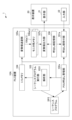
- FIG. 2 is a diagram illustrating an example of a functional block configuration of the PLC system according to the first embodiment.
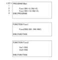
- FIG. 4 is a diagram illustrating an example of a sequence program.
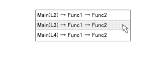
- FIG. 13 is a diagram showing an example of a list of the invocation order of POUs to be monitored.
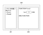
- FIG. 13 is a diagram showing an example of a screen displaying variable values of a POU to be monitored.
- 10 is a flowchart illustrating a debugging process of the PLC device.
- FIG. 11 is a functional block diagram illustrating an example of a functional configuration of a PLC system according to a second embodiment.
- FIG. 4 is a diagram illustrating an example of a sequence program.
- FIG. 13 is a diagram showing an example of a screen displaying variable values of two monitored POUs.
- 10 is a flowchart illustrating a debugging process of the PLC device.
- FIG. 1 is a diagram showing an example of a conventional display of variable values of a POU.
- FIG. 1 is a diagram illustrating an example of a functional block configuration of a PLC system according to a first embodiment.
- a PLC system 1 includes a PLC device 10 and a display device 20.
- the PLC device 10 includes a function of a debugging device. Note that the present invention can also be applied to a case where the PLC device 10 and the debugging device are different devices.
- the PLC device 10 and the display device 20 are directly connected to each other via a connection interface (not shown).
- the PLC device 10 and the display device 20 may be connected to each other and communicate with each other via a network (not shown), such as a LAN (Local Area Network) or the Internet.
- a network not shown
- the PLC device 10 and the display device 20 are provided with a communication unit (not shown) for communicating with each other via such a connection.
- the PLC device 10 and the display device 20 are described as being different devices, but as will be described later, the display device 20 may be included in the PLC device 10 .
- the display device 20 is, for example, a computer or a tablet terminal known to those skilled in the art, and includes a display unit 21 and an input unit 22 .
- the display unit 21 is, for example, a liquid crystal display, etc.
- the display unit 21 displays the variable values of the POUs to be monitored in the calling order received from the user via the input unit 22, which will be described later.
- the input unit 22 is, for example, a keyboard or a touch panel arranged on the display unit 21, and receives inputs from the user, such as the call order of the POUs to be monitored.
- the PLC device 10 includes a call order receiving unit 101, a POU call management unit 102, a sequence program execution unit 103, an I/O memory 104, a variable value saving unit 105, a monitor memory 106, a variable value output unit 107, and a call order storage unit 108.
- the sequence program execution unit 103 includes an analysis unit 1031.
- the PLC device 10 has a sequence program SP stored in a read only memory (ROM) or a hard disk drive (HDD), neither of which are shown.
- the PLC device 10 includes a processor (not shown) such as a central processing unit (CPU) to realize the operation of the functional blocks in Fig. 1.
- the PLC device 10 also includes auxiliary storage devices (not shown) such as a ROM or HDD that stores various control programs, and a main storage device (not shown) such as a random access memory (RAM) for storing data temporarily required for the processor to execute the programs.
- auxiliary storage devices such as a ROM or HDD that stores various control programs
- main storage device such as a random access memory (RAM) for storing data temporarily required for the processor to execute the programs.
- RAM random access memory
- the arithmetic processing unit reads application software such as the OS and debug programs from the auxiliary storage device, and performs arithmetic processing based on the OS and application software while expanding the OS and application software that have been read into the main storage device. Based on the results of this calculation, the PLC device 10 controls each piece of hardware. In this way, the processing by the functional blocks in Figure 1 is realized. In other words, the PLC device 10 can be realized by the cooperation of hardware and software.
- the call order receiving unit 101 receives, via the input unit 22 of the display device 20, the call order of the POUs to be monitored, which is specified by the user in a sequence program SP, which will be described later.
- 2 is a diagram showing an example of a sequence program SP.
- the upper part of Fig. 2 shows the main sequence program SP, and the middle and lower parts show functions Func1 and Func2, which are POUs.
- the call order receiving unit 101 displays, for example, the sequence program SP on the display unit 21 of the display device 20.
- the call order receiving unit 101 receives a path of the call order of the function Func2 as text (for example, "Main#L3 ⁇ Func1 ⁇ Func2") from the user via the input unit 22.
- the call order acceptance unit 101 may accept the call order of the POUs to be monitored by zooming (jumping to the definition) the cursor or mouse pointer of the input unit 22 to the position of function Func1 on the third line on the screen of the sequence program SP on the display unit 21 based on the user's input operation.
- the call order receiving unit 101 displays, on the display unit 21, a list of previously received POU call orders stored in a call order storage unit 108 described later and call locations of POUs to be monitored detected by an analysis of a sequence program SP by an analysis unit 1031 described later.
- the call order receiving unit 101 may receive, via the input unit 22, a call order for Func2, which is a POU to be monitored and selected by the user from the list.
- the POU invocation management unit 102 monitors the invocation order of the POUs, for example, when a sequence program SP is executed by a sequence program execution unit 103 described later. If the invocation order matches the invocation order of the POUs to be monitored accepted by the invocation order acceptance unit 101, the POU invocation management unit 102 instructs a variable value saving unit 105 described later to acquire a snapshot of the variable values of the POUs to be monitored.
- the POU call management unit 102 determines that the call order of the POU is "Main (L2) -> Func1 ->Func2", which is different from the call order of the monitored POU accepted by the call order acceptance unit 101.
- the POU call management unit 102 instructs the variable value saving unit 105, which will be described later, to acquire a snapshot of the variable values of the POU to be monitored.
- the variable value saving unit 105 which will be described later, reads the variable values of the instructed POU to be monitored from the I/O memory 104, which will be described later, and stores and saves the read variable values of the POU to be monitored in the monitor memory 106, which will be described later.
- the sequence program execution unit 103 reads and executes the sequence program SP from an auxiliary storage device (not shown).
- the sequence program execution unit 103 reads and writes the values of each variable of the sequence program SP to the I/O memory 104 (described later).
- the analysis unit 1031 detects the call locations of the POUs to be monitored that are accepted by the call order acceptance unit 101 from the sequence program SP executed by the sequence program execution unit 103.
- the analysis unit 1031 stores the detected call locations of the POUs to be monitored in the call order storage unit 108, which will be described later.
- the I/O memory 104 is an I/O memory known to those skilled in the art, and stores variable values, etc. at addresses specified in response to commands of the sequence program SP executed by the sequence program execution unit 103.
- variable value saving unit 105 when the variable value saving unit 105 receives a command from the POU call management unit 102 to obtain a snapshot of the variable values of the POUs to be monitored that have been accepted by the call order acceptance unit 101, the variable value saving unit 105 reads the variable values of the POUs to be monitored from the I/O memory 104.
- the variable value saving unit 105 stores and saves the read variable values of the POUs to be monitored in the monitor memory 106 described below.
- the monitor memory 106 is, for example, a memory such as a RAM, and stores the variable values of the POU to be monitored that are read from the I/O memory 104 by the variable value saving unit 105.
- the variable value output unit 107 outputs the variable values of the POU to be monitored stored in the monitor memory 106 to the display unit 21 of the display device 20.
- the display unit 21 of the display device 20 displays the variable values of the POU to be monitored stored (saved) in the monitor memory 106.
- FIG. 4 is a diagram showing an example of a screen 200 that displays the variable values of the POU to be monitored. As shown in FIG. 4, screen 200 has a display area 201 that displays the variable value "5" of variable "Var1" of function Func2 that is called from function Func1 of Main (line 3) of sequence program SP stored (saved) in monitor memory 106, and a display area 202 that displays the POU to be monitored. In this way, the PLC device 10 (debugging device) can monitor the variable values of the POUs in any calling order designated by the user.
- the call order storage unit 108 is, for example, a ROM or an EPROM (Erasable Programmable Read Only Memory), and stores the call order.
- the call order memory unit 108 stores the call order accepted by the call order acceptance unit 101 as a past call order, and also stores the call locations of the monitored POUs detected from the sequence program SP by the analysis unit 1031.
- FIG. 5 is a flowchart for explaining the debugging process of the PLC device 10. The flow shown here is executed every time the calling order of the POUs to be monitored is received from the user via the input unit 22 of the display device 20.
- step S11 the call order receiving unit 101 receives the call order of the POUs to be monitored that is specified by the user in the sequence program SP via the input unit 22 of the display device 20.
- the call order receiving unit 101 stores the received call order of the POUs to be monitored in the call order storage unit 108.
- step S12 the sequence program execution unit 103 executes the sequence program SP.
- the sequence program execution unit 103 reads and writes the values of each variable of the sequence program SP to the I/O memory 104.
- step S13 the analysis unit 1031 detects the call locations of the POUs to be monitored that were accepted in step S11 from the sequence program SP executed in step S12.
- the analysis unit 1031 stores the detected call locations of the POUs to be monitored in the call order storage unit 108.
- step S14 the POU call management unit 102 monitors the calling order of the POUs of the sequence program SP executed in step S12, and determines whether the calling order of the sequence program SP being executed matches the calling order of the POUs to be monitored that were accepted in step S11. If the calling order of the sequence program SP being executed matches the calling order of the POUs to be monitored that were accepted in step S11, the process proceeds to step S15. On the other hand, if the calling order of the sequence program being executed does not match the calling order of the POUs to be monitored that were accepted in step S11, the process waits in step S14 until they match.
- step S15 the POU call management unit 102 instructs the variable value saving unit 105 to obtain a snapshot of the variable values in the POU to be monitored.
- step S16 the variable value saving unit 105 reads the variable values of the POU to be monitored from the I/O memory 104 based on the command in step S15, and stores and saves the read variable values of the POU to be monitored in the monitor memory 106.
- step S17 the variable value output unit 107 outputs the variable values of the POU to be monitored that were saved in the monitor memory 106 in step S16 to the display unit 21 of the display device 20.
- the display unit 21 of the display device 20 displays the variable values of the POU to be monitored that were stored (saved) in the monitor memory 106.
- the PLC device 10 can monitor the variable values of POUs in any calling order designated by the user.
- the first embodiment has been described above.
- the PLC device 10 accepts the call order of a single monitored POU and displays the variable values of the accepted single monitored POU on the display unit 21 of the display device 20.
- the PLC device 10A accepts the call order of two or more monitored POUs and simultaneously displays the variable values of the accepted multiple monitored POUs on the display unit 21 of the display device 20, which is different from the first embodiment.
- the PLC device 10A according to the second embodiment can monitor the variable values of POUs in any calling order designated by the user.
- the second embodiment will now be described.
- Fig. 6 is a functional block diagram showing an example of the functional configuration of a PLC system according to a second embodiment. Elements having the same functions as those of the PLC system 1 in Fig. 1 are denoted by the same reference numerals, and detailed description thereof will be omitted.
- the PLC system 1 according to the second embodiment includes a PLC device 10A and a display device 20.
- the display device 20 has the same functions as the display device 20 in the first embodiment.
- the display unit 21 and the input unit 22 have the same functions as the display unit 21 and the input unit 22 in the first embodiment.
- the PLC device 10A includes a call order receiving unit 101a, a POU call management unit 102a, a sequence program execution unit 103, an I/O memory 104, a variable value saving unit 105a, monitor memories 106a(1)-106a(n), a variable value output unit 107a, and a call order storage unit 108.
- the sequence program execution unit 103 also includes an analysis unit 1031.
- n is an integer of 2 or more.
- the sequence program execution unit 103, the I/O memory 104, and the calling order storage unit 108 have the same functions as the sequence program execution unit 103, the I/O memory 104, and the calling order storage unit 108 in the first embodiment.
- the analysis unit 1031 has the same functions as the analysis unit 1031 in the first embodiment.
- the call order receiving unit 101a receives, via the input unit 22 of the display device 20, the call order of two or more POUs to be monitored, which are designated by the user in the sequence program SP2 shown in FIG. 7 is a diagram showing an example of the sequence program SP2.
- the upper part of Fig. 7 shows the main sequence program SP2, and the middle and lower parts show functions Func1 and Func2, which are POUs.
- Func1 and Func2 which are POUs.
- the call order receiving unit 101a displays the sequence program SP2 on the display unit 21 of the display device 20.
- the call order receiving unit 101a receives a path of the call order of the function Func2 as text (e.g., "Main#L2 ⁇ Func1 ⁇ Func2" and "Main#L3 ⁇ Func1 ⁇ Func2") from the user via the input unit 22.
- the call order acceptance unit 101a may accept the call order of the two monitored POUs by zooming (jumping to the definition) the cursor or mouse pointer of the input unit 22 to the position of function Func1 on the second and third lines on the screen of the sequence program SP2 of the display unit 21 based on the user's input operation.
- the call order receiving unit 101a displays on the display unit 21 the call orders of previously received POUs stored in the call order storage unit 108 and a list of call locations of POUs to be monitored detected by the analysis of the sequence program SP by the analysis unit 1031.
- the call order receiving unit 101a may receive, via the input unit 22, the call order of Func2 of two POUs to be monitored selected by the user from the list.
- the call order receiving unit 101a may receive the call order for different POUs, for example, Func1 and Func2, as POUs to be monitored.
- the POU call management unit 102a monitors the POU call order when the sequence program SP2 is executed by the sequence program execution unit 103. That is, the POU call management unit 102a determines whether the POU call order in the sequence program SP2 executed by the sequence program execution unit 103 matches each of the call orders of the two monitored POUs accepted by the call order acceptance unit 101a.
- the POU invocation management unit 102a instructs the variable value backup unit 105a, described later, to obtain a snapshot of the variable values of the matching monitored POUs each time the POU invocation order in the executed sequence program SP2 matches with the invocation order of the two monitored POUs that it has received.
- variable value saving unit 105a Similar to the variable value saving unit 105 in the first embodiment, each time the variable value saving unit 105a receives a command from the POU call management unit 102a to obtain a snapshot of the variable values of each of the two monitored POUs received by the call order receiving unit 101, the variable value saving unit 105a reads out the variable values of the monitored POUs from the I/O memory 104.
- the variable value saving unit 105a stores and saves the read variable values of the monitored POUs in the monitor memories 106a(1) to 106a(n) described below, in order, starting from the monitor memory 106a(1).
- Each of the monitor memories 106a(1) to 106a(n) is a memory such as a RAM, similar to the monitor memory 106 in the first embodiment, and the variable values of the two monitored POUs read out from the I/O memory 104 by the variable value saving unit 105a are stored, for example, in the monitor memories 106a(1) and 106a(2).
- the monitor memories 106a(1) to 106a(n) are different monitor memories, this is not limiting.
- the monitor memories 106a(1) to 106a(n) may be different storage areas on a single monitor memory.
- the variable value output unit 107a outputs the variable values of the multiple POUs to be monitored that are stored in the monitor memories 106a(1) to 106a(n) to the display unit 21 of the display device 20.
- the display unit 21 of the display device 20 displays the variable values of the POUs to be monitored that are stored (saved) in the monitor memories 106a(1) to 106a(n).
- FIG. 8 is a diagram showing an example of a screen 300 displaying the variable values of two monitored POUs.
- the screen 300 has a display area 301 that displays, for example, the variable values "3" and "5" of the variables "Var1” and “Var2" of the function Func2 called from the function Func1 of Main (line 2) of the sequence program SP2 stored (saved) in the monitor memory 106a(1), and the POU to be monitored.
- the screen 300 also has a display area 302 that displays the variable values "10" and "5" of the variables "Var1” and “Var2” of the function Func2 called from the function Func1 of Main (line 3) of the sequence program SP2 stored (saved) in the monitor memory 106a(2), and the POU to be monitored. That is, the screen 300 simultaneously displays the variable values of the two POUs to be monitored. In this way, the PLC device 10A (debugging device) can monitor the variable values of the POUs in any calling order designated by the user.
- the screen 300 may be configured to highlight, in a display format of a color such as red, the variable values that are different from each other among the variable values of the POUs to be monitored on the second and third lines of the sequence program SP2. Also, the screen 300 may be configured to highlight, in a display format of a line type such as a thick line, a color, or the like, that the lines of the POUs to be monitored are different. This allows the user to easily understand the difference in variable values of POUs in any designated calling order. Furthermore, when the call order receiving unit 101a receives a call order with different POUs, for example Func1 and Func2, as POUs to be monitored, the display unit 21 of the display device 20 may be configured to simultaneously display the different POUs.
- a line type such as a thick line, a color, or the like
- FIG. 9 is a flowchart for explaining the debugging process of the PLC device 10 A. The flow shown here is executed every time a calling order of a plurality of POUs to be monitored is received from the user via the input unit 22 of the display device 20.
- step S21 the call order receiving unit 101a receives the call order of the multiple POUs to be monitored that are specified by the user in the sequence program SP2 via the input unit 22 of the display device 20.
- the call order receiving unit 101 stores the received call order of the multiple POUs to be monitored in the call order storage unit 108.
- step S22 the sequence program execution unit 103 executes the sequence program SP2.
- the sequence program execution unit 103 reads and writes the values of each variable of the sequence program SP2 to the I/O memory 104.
- step S23 the analysis unit 1031 detects the call locations of each of the multiple monitored POUs received in step S21 from the sequence program SP2 executed in step S22.
- the analysis unit 1031 stores the detected call locations of the multiple monitored POUs in the call order storage unit 108.
- step S24 the POU call management unit 102 monitors the calling order of the POUs of the sequence program SP2 executed in step S22, and determines whether the calling order of the sequence program SP2 being executed matches the calling order of one of the multiple monitored POUs received in step S21. If the calling order of the sequence program being executed matches the calling order of the monitored POUs received in step S21, processing proceeds to step S25. On the other hand, if the calling order of the sequence program SP2 being executed does not match the calling order of the one monitored POU received in step S21, processing waits in step S24 until they match.
- step S25 the POU call management unit 102a instructs the variable value backup unit 105a to obtain a snapshot of the variable values in one monitored POU.
- step S26 the variable value saving unit 105a reads the variable values of one monitored POU from the I/O memory 104 based on the command in step S25, and stores and saves the read variable values of one monitored POU in the monitor memory 106a(i) (i is an integer from 1 to n).
- step S27 the POU call management unit 102a determines whether or not snapshots of the variables of all monitored POUs received in step S21 have been obtained. If snapshots of the variables of all monitored POUs have been obtained, the process proceeds to step S28. On the other hand, if snapshots of the variables of all monitored POUs have not been obtained, the process returns to step S24.
- step S28 the variable value output unit 107a outputs the variable values of the multiple monitored POUs saved in the monitor memories 106a(1)-106a(n) to the display unit 21 of the display device 20.
- the display unit 21 of the display device 20 displays the variable values of the multiple monitored POUs stored (saved) in the monitor memories 106a(1)-106a(n).
- the PLC device 10A can monitor the variable values of POUs in any calling order designated by the user.
- the second embodiment has been described above.
- the PLC devices 10 and 10A according to the first and second embodiments can monitor the variable values of POUs in any calling order specified by the user.
- the PLC devices 10 and 10A include the functionality of a debugging device, but are not limited to this.
- the PLC devices 10 and 10A and the debugging device may be different devices.
- the PLC devices 10, 10A and the display device 20 are described as being different devices, but the display device 20 may be included in the PLC devices 10, 10A.
- the PLC devices 10, 10A include the functionality of a debugging device, but this is not limited to this.
- the PLC devices 10, 10A and the debugging device may be configured as different devices.
- the debugging device may instruct the PLC devices 10, 10A to execute the sequence programs SP, SP2.
- the PLC devices 10, 10A output the variable values of the POUs to be monitored, but this is not limited to the above.
- the PLC devices 10, 10A may output the variable values in a file format including a time series (e.g., csv, txt, etc.) or simply as a single data (packet) on a network as the output data format in order to be usable by any tool, not limited to the monitor function. This allows the data to be tallied by a host PC that monitors multiple PLC devices 10, 10A, or to be used for a trace function.
- each function included in the PLC devices 10 and 10A in the first and second embodiments can be realized by hardware, software, or a combination of these.
- being realized by software means being realized by a computer reading and executing a program.
- Non-transitory computer readable media include various types of tangible storage media. Examples of non-transitory computer readable media include magnetic recording media (e.g., flexible disks, magnetic tapes, hard disk drives), magneto-optical recording media (e.g., magneto-optical disks), CD-ROMs (Read Only Memory), CD-Rs, CD-R/Ws, and semiconductor memories (e.g., mask ROMs, PROMs (Programmable ROMs), EPROMs (Erasable PROMs), flash ROMs, RAMs).
- the program may also be provided to the computer by various types of temporary computer readable media. Examples of temporary computer readable media include electrical signals, optical signals, and electromagnetic waves.
- the temporary computer readable medium can provide the program to the computer via a wired communication path such as an electric wire or optical fiber, or via a wireless communication path.
- the step of writing the program to be recorded on the recording medium includes not only processes that are performed chronologically according to the order, but also processes that are not necessarily performed chronologically but are executed in parallel or individually.
- the step of writing the program may also be performed by cloud computing.
- the debugging device (10) includes a call order receiving unit (101) that receives the call order of POUs to be monitored in a sequence program (SP), a POU call management unit (102) that monitors the POU call order when the sequence program (SP) is executed, and issues a command to obtain a snapshot of the variable values of the POUs to be monitored when the POU call order matches the call order of the POUs to be monitored received by the call order receiving unit (101), a variable value save unit (105) that obtains a snapshot of the variable values of the POUs to be monitored based on the command and saves the variable values of the POUs to be monitored, and a monitor memory (106) that stores the saved variable values of the POUs to be monitored.
- SP sequence program
- SP sequence program
- SP sequence program
- SP sequence program
- a variable value save unit (105) that obtains a snapshot of the variable values of the POUs to be monitored based on the command and saves the variable values of the POUs to be monitored
- the call order receiving unit (101) receives the call order of the POUs to be monitored by at least one of a zoom operation on a sequence program screen and a path specification by text.
- the debugging device (10) of Supplementary Note 1 or Supplementary Note 2 is provided with a calling order storage unit (108) that stores a calling order, and the calling order receiving unit (101) selects and receives the calling order of the POU to be monitored from the calling orders stored in the calling order storage unit (108).
- the debugging device (10) of Appendix 3 includes an analysis unit (1031) that detects the call locations of the POUs to be monitored from the sequence program (SP), and the call order storage unit (108) stores the call order specified by the call order receiving unit (101) and also stores the call locations of the POUs to be monitored detected by the analysis unit (1031).
- the debugging device (10A) of Supplementary Note 1 or Supplementary Note 2 includes a plurality of monitor memories (106a(1) to 106a(n)) for storing variable values of a plurality of POUs to be monitored, and a variable value output unit (107a) for outputting the variable values of the plurality of POUs to be monitored for simultaneous display.
- variable value output unit (107a) In the debugging device (10A) of supplementary note 5, the variable value output unit (107a) outputs the variable values of a plurality of POUs to be monitored simultaneously in different display formats.
- the debugging device (10, 10A) of Supplementary Note 1 or Supplementary Note 2 is provided with a display device (20) for displaying the variable values of the POU to be monitored.
- the debugging device (10, 10A) of Supplementary Note 1 or Supplementary Note 2 includes a variable value output unit (107, 107a) that outputs the variable values of the POU to be monitored in a file format including a time series or as single data on a network.
- the PLC device (10, 10A) is equipped with the debugging device of Supplementary Note 1 or Supplementary Note 2.
- the recording medium is a computer-readable recording medium having recorded thereon a debug program that causes a computer to function as a debug device (10), the recording medium comprising: a call order acceptance unit (101) that accepts the call order of POUs to be monitored in a sequence program (SP); a POU call management unit (102) that monitors the call order of POUs when the sequence program (SP) is executed, and issues a command to obtain a snapshot of the variable values of the POUs to be monitored if the call order matches the call order of the POUs to be monitored accepted by the call order acceptance unit (101); a variable value save unit (105) that acquires a snapshot of the variable values of the POUs to be monitored based on the command and saves the variable values of the POUs to be monitored; and a monitor memory (106) that stores the saved variable values of the POUs to be monitored.
Landscapes
- Physics & Mathematics (AREA)
- General Physics & Mathematics (AREA)
- Engineering & Computer Science (AREA)
- Automation & Control Theory (AREA)
- Debugging And Monitoring (AREA)
Abstract
ユーザが指定した任意の呼出し順のPOUの変数値をモニタすること。 デバッグ装置は、シーケンスプログラムのうちモニタ対象のPOUの呼出し順を受け付ける呼出し順受付部と、前記シーケンスプログラムの実行時にPOUの呼出し順を監視して、前記呼出し順受付部により受け付けた前記モニタ対象のPOUの呼出し順と合致する場合に、前記モニタ対象のPOUの変数値のスナップショットの取得を指令するPOU呼出し管理部と、前記指令に基づいて前記モニタ対象のPOUの変数値のスナップショットを取得し前記モニタ対象のPOUの変数値を退避させる変数値退避部と、退避された前記モニタ対象のPOUの変数値を記憶するモニタ用メモリと、を備える。
Description
本開示は、シーケンスプログラムのPOUの変数値を表示するデバッグ装置、PLC装置及び記録媒体に関する。
PLC(Programmable Logic Controller)装置のシーケンスプログラムはIEC61131-3で規格化されている。シーケンスプログラムは、ファンクションブロックやファンクション等のPOU(プログラム構成要素、Program Organization Units)によって構成される。
一般的に、PLC装置のシーケンスプログラムの動作を確認する方法は2つがある。
(1)ステップ実行でデバッグする方法
(2)モニタ機能(プログラムを停止させない)
後者のモニタ機能は、動作中のPLC装置と通信することで、変数値をリアルタイムでモニタすることができる。
例えば、シーケンスプログラムにおけるモニタ範囲を指定し、モニタ範囲の実行状態(実行中/実行後/非実行時)に応じて適切なモニタ方法を選択する技術が知られている。例えば、特許文献1参照。
一般的に、PLC装置のシーケンスプログラムの動作を確認する方法は2つがある。
(1)ステップ実行でデバッグする方法
(2)モニタ機能(プログラムを停止させない)
後者のモニタ機能は、動作中のPLC装置と通信することで、変数値をリアルタイムでモニタすることができる。
例えば、シーケンスプログラムにおけるモニタ範囲を指定し、モニタ範囲の実行状態(実行中/実行後/非実行時)に応じて適切なモニタ方法を選択する技術が知られている。例えば、特許文献1参照。
モニタ機能には、シーケンスプログラムを停止するデバッグ機能(ステップ実行)と異なり、以下のメリットがあり、PLCモニタ装置に広く普及している。
(a)プログラムを停止させずに動作を確認できる(機械の他の機能が動作したまま、シーケンスプログラムだけを停止すると危険)
(b)リアルな動作を確認可能(シーケンスプログラムを停止することで周辺動作とのタイミングのずれが生じる可能性がある)
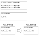
従来は、プログラムを停止しないため、特定のプログラム部における変数値をモニタできない課題があった。そこで、特許文献1に記載の技術では、当該課題を解消している。しかしながら、特許文献1に記載の技術では、図10に示すように、モニタ対象をモニタ開始アドレス及びモニタ終了アドレスを指定するため、モニタ対象が複数個所から呼出されるPOU内におけるプログラム部の場合、呼出し順毎に異なる変数値をモニタできないという課題がある。
例えば、図10の上段に示すメインのシーケンスプログラムが、中段に示すPOUであるファンクションFunc1の変数「Var1」を呼び出す場合、Func1(IN:=3)の呼出し順Aと、Func1(IN:=5)の呼出し順Bとは、変数「Var1」の状態が異なる。このため、図10の下段に示すように、特許文献1に記載の技術では、呼出し箇所毎の変数「Var1」の状態はモニタできない。
(a)プログラムを停止させずに動作を確認できる(機械の他の機能が動作したまま、シーケンスプログラムだけを停止すると危険)
(b)リアルな動作を確認可能(シーケンスプログラムを停止することで周辺動作とのタイミングのずれが生じる可能性がある)
従来は、プログラムを停止しないため、特定のプログラム部における変数値をモニタできない課題があった。そこで、特許文献1に記載の技術では、当該課題を解消している。しかしながら、特許文献1に記載の技術では、図10に示すように、モニタ対象をモニタ開始アドレス及びモニタ終了アドレスを指定するため、モニタ対象が複数個所から呼出されるPOU内におけるプログラム部の場合、呼出し順毎に異なる変数値をモニタできないという課題がある。
例えば、図10の上段に示すメインのシーケンスプログラムが、中段に示すPOUであるファンクションFunc1の変数「Var1」を呼び出す場合、Func1(IN:=3)の呼出し順Aと、Func1(IN:=5)の呼出し順Bとは、変数「Var1」の状態が異なる。このため、図10の下段に示すように、特許文献1に記載の技術では、呼出し箇所毎の変数「Var1」の状態はモニタできない。
そこで、ユーザが指定した任意の呼出し順のPOUの変数値をモニタすることが望まれている。
(1)本開示のデバッグ装置の一態様は、シーケンスプログラムのうちモニタ対象のPOU(Program Organization Units)の呼出し順を受け付ける呼出し順受付部と、前記シーケンスプログラムの実行時にPOUの呼出し順を監視して、前記呼出し順受付部により受け付けた前記モニタ対象のPOUの呼出し順と合致する場合に、前記モニタ対象のPOUの変数値のスナップショットの取得を指令するPOU呼出し管理部と、前記指令に基づいて前記モニタ対象のPOUの変数値のスナップショットを取得し前記モニタ対象のPOUの変数値を退避させる変数値退避部と、退避された前記モニタ対象のPOUの変数値を記憶するモニタ用メモリと、を備える。
(2)本開示のPLC装置の一態様は、(1)のデバッグ装置を備える。
(3)本開示の記録媒体の一態様は、コンピュータを、デバッグ装置として動作させるために、シーケンスプログラムのうちモニタ対象のPOUの呼出し順を受け付ける呼出し順受付部と、前記シーケンスプログラムの実行時にPOUの呼出し順を監視して、前記呼出し順受付部により受け付けた前記モニタ対象のPOUの呼出し順と合致する場合に、前記モニタ対象のPOUの変数値のスナップショットの取得を指令するPOU呼出し管理部と、前記指令に基づいて前記モニタ対象のPOUの変数値のスナップショットを取得し前記モニタ対象のPOUの変数値を退避させる変数値退避部と、退避された前記モニタ対象のPOUの変数値を記憶するモニタ用メモリと、として機能させるデバッグプログラムを記録したコンピュータが読み取り可能な記録媒体。
<第1実施形態>
以下、第1実施形態に係るPLCシステムについて、図を参照しながら詳細に説明する。
図1は、第1実施形態に係るPLCシステムの機能ブロック構成の一例を示す図である。
図1に示すように、PLCシステム1は、PLC装置10、及び表示装置20を有する。ここでは、PLC装置10は、デバッグ装置の機能を含む場合を例示する。なお、本発明は、PLC装置10と、デバッグ装置とが互いに異なる装置の場合でも適用することができる。
以下、第1実施形態に係るPLCシステムについて、図を参照しながら詳細に説明する。
図1は、第1実施形態に係るPLCシステムの機能ブロック構成の一例を示す図である。
図1に示すように、PLCシステム1は、PLC装置10、及び表示装置20を有する。ここでは、PLC装置10は、デバッグ装置の機能を含む場合を例示する。なお、本発明は、PLC装置10と、デバッグ装置とが互いに異なる装置の場合でも適用することができる。
PLC装置10、及び表示装置20は、図示しない接続インタフェースを介して互いに直接接続される。なお、PLC装置10、及び表示装置20は、LAN(Local Area Network)やインターネット等の図示しないネットワークを介して相互に接続されて通信を行うようにしてもよい。この場合、PLC装置10、及び表示装置20は、かかる接続によって相互に通信を行うための図示しない通信部を備えている。
また、PLC装置10と、表示装置20とは、互いに異なる装置としたが、後述するように、表示装置20は、PLC装置10に含まれてもよい。
また、PLC装置10と、表示装置20とは、互いに異なる装置としたが、後述するように、表示装置20は、PLC装置10に含まれてもよい。
<表示装置20>
表示装置20は、例えば、当業者にとって公知のコンピュータやタブレット端末であり、表示部21、及び入力部22を有する。
表示部21は、例えば、液晶ディスプレイ等である。表示部21は、後述する入力部22を介して、ユーザから受け付けた呼出し順のモニタ対象のPOUの変数値等を表示する。
入力部22は、例えば、キーボードや、表示部21に配置されたタッチパネル等であり、モニタ対象のPOUの呼出し順等の入力をユーザから受け付ける。
表示装置20は、例えば、当業者にとって公知のコンピュータやタブレット端末であり、表示部21、及び入力部22を有する。
表示部21は、例えば、液晶ディスプレイ等である。表示部21は、後述する入力部22を介して、ユーザから受け付けた呼出し順のモニタ対象のPOUの変数値等を表示する。
入力部22は、例えば、キーボードや、表示部21に配置されたタッチパネル等であり、モニタ対象のPOUの呼出し順等の入力をユーザから受け付ける。
<PLC装置10>
図1に示すように、本実施形態に係るPLC装置10は、呼出し順受付部101、POU呼出し管理部102、シーケンスプログラム実行部103、I/Oメモリ104、変数値退避部105、モニタ用メモリ106、変数値出力部107、及び呼出し順記憶部108を含んで構成される。また、シーケンスプログラム実行部103は、解析部1031を含む。また、PLC装置10は、シーケンスプログラムSPを図示しないROM(Read Only Memory)やHDD(Hard Disk Drive)等に有する。
なお、PLC装置10は、図1の機能ブロックの動作を実現するために、CPU(Central Processing Unit)等の図示しない演算処理装置を備える。また、PLC装置10は、各種の制御用プログラムを格納したROMやHDD等の図示しない補助記憶装置や、演算処理装置がプログラムを実行する上で一時的に必要とされるデータを格納するためのRAM(Random Access Memory)といった図示しない主記憶装置を備える。
図1に示すように、本実施形態に係るPLC装置10は、呼出し順受付部101、POU呼出し管理部102、シーケンスプログラム実行部103、I/Oメモリ104、変数値退避部105、モニタ用メモリ106、変数値出力部107、及び呼出し順記憶部108を含んで構成される。また、シーケンスプログラム実行部103は、解析部1031を含む。また、PLC装置10は、シーケンスプログラムSPを図示しないROM(Read Only Memory)やHDD(Hard Disk Drive)等に有する。
なお、PLC装置10は、図1の機能ブロックの動作を実現するために、CPU(Central Processing Unit)等の図示しない演算処理装置を備える。また、PLC装置10は、各種の制御用プログラムを格納したROMやHDD等の図示しない補助記憶装置や、演算処理装置がプログラムを実行する上で一時的に必要とされるデータを格納するためのRAM(Random Access Memory)といった図示しない主記憶装置を備える。
そして、PLC装置10において、演算処理装置が補助記憶装置からOSやデバッグプログラム等のアプリケーションソフトウェアを読み込み、読み込んだOSやアプリケーションソフトウェアを主記憶装置に展開させながら、これらのOSやアプリケーションソフトウェアに基づいた演算処理を行なう。この演算結果に基づいて、PLC装置10が各ハードウェアを制御する。これにより、図1の機能ブロックによる処理は実現される。すなわち、PLC装置10は、ハードウェアとソフトウェアが協働することにより実現することができる。
呼出し順受付部101は、表示装置20の入力部22を介して、後述するシーケンスプログラムSPのうちユーザにより指定されたモニタ対象のPOUの呼出し順を受け付ける。
図2は、シーケンスプログラムSPの一例を示す図である。図2の上段では、メインのシーケンスプログラムSPを示し、中段及び下段ではPOUであるファンクションFunc1及びFunc2を示す。
具体的には、呼出し順受付部101は、例えば、シーケンスプログラムSPを表示装置20の表示部21に表示する。例えば、シーケンスプログラムSPの3行目のファンクションFunc1から呼び出されるファンクションFunc2をモニタ対象のPOUとし、Func2の変数値をモニタする場合、呼出し順受付部101は、入力部22を介してユーザからファンクションFunc2の呼出し順のパスをテキスト(例えば、「Main#L3¥Func1¥Func2」等)で受け付ける。
あるいは、呼出し順受付部101は、ユーザの入力操作に基づいて入力部22のカーソルやマウスポインタを、表示部21のシーケンスプログラムSPの画面上の3行目のファンクションFunc1の位置に合わせてズームする(定義に飛ぶ)ことで、モニタ対象のPOUの呼出し順を受け付けるようにしてもよい。
また、呼出し順受付部101は、図3に示すように、後述する呼出し順記憶部108に記憶される、過去に受け付けたPOUの呼出し順や、後述する解析部1031によるシーケンスプログラムSPの解析によって検出されたモニタ対象のPOUの呼出し箇所の一覧を、表示部21に表示する。呼出し順受付部101は、入力部22を介して、一覧からユーザにより選択されたモニタ対象のPOUであるFunc2の呼出し順を受け付けるようにしてもよい。
図2は、シーケンスプログラムSPの一例を示す図である。図2の上段では、メインのシーケンスプログラムSPを示し、中段及び下段ではPOUであるファンクションFunc1及びFunc2を示す。
具体的には、呼出し順受付部101は、例えば、シーケンスプログラムSPを表示装置20の表示部21に表示する。例えば、シーケンスプログラムSPの3行目のファンクションFunc1から呼び出されるファンクションFunc2をモニタ対象のPOUとし、Func2の変数値をモニタする場合、呼出し順受付部101は、入力部22を介してユーザからファンクションFunc2の呼出し順のパスをテキスト(例えば、「Main#L3¥Func1¥Func2」等)で受け付ける。
あるいは、呼出し順受付部101は、ユーザの入力操作に基づいて入力部22のカーソルやマウスポインタを、表示部21のシーケンスプログラムSPの画面上の3行目のファンクションFunc1の位置に合わせてズームする(定義に飛ぶ)ことで、モニタ対象のPOUの呼出し順を受け付けるようにしてもよい。
また、呼出し順受付部101は、図3に示すように、後述する呼出し順記憶部108に記憶される、過去に受け付けたPOUの呼出し順や、後述する解析部1031によるシーケンスプログラムSPの解析によって検出されたモニタ対象のPOUの呼出し箇所の一覧を、表示部21に表示する。呼出し順受付部101は、入力部22を介して、一覧からユーザにより選択されたモニタ対象のPOUであるFunc2の呼出し順を受け付けるようにしてもよい。
POU呼出し管理部102は、例えば、後述するシーケンスプログラム実行部103によるシーケンスプログラムSPの実行時にPOUの呼出し順を監視する。POU呼出し管理部102は、呼出し順受付部101により受け付けたモニタ対象のPOUの呼出し順と合致する場合に、モニタ対象のPOUの変数値のスナップショットの取得を、後述する変数値退避部105に指令する。
具体的には、POU呼出し管理部102は、例えば、シーケンスプログラム実行部103がシーケンスプログラムSPの2行目のFunc1(IN1:=3)を実行する場合、当該POUの呼出し順が「Main(L2)->Func1->Func2」であることから、呼出し順受付部101により受け付けたモニタ対象のPOUの呼出し順と異なると判定する。
一方、POU呼出し管理部102は、シーケンスプログラム実行部103がシーケンスプログラムSPの3行目のFunc1(IN1:=5)を実行する場合、当該POUの呼出し順が「Main(L3)->Func1->Func2」であることから、呼出し順受付部101により受け付けたモニタ対象のPOUの呼出し順と合致すると判定する。この場合、POU呼出し管理部102は、モニタ対象のPOUの変数値のスナップショットの取得を、後述する変数値退避部105に指令する。後述する変数値退避部105は、指令されたモニタ対象のPOUの変数値を、後述するI/Oメモリ104から読み出して、読み出したモニタ対象のPOUの変数値を後述するモニタ用メモリ106に記憶し退避させる。
具体的には、POU呼出し管理部102は、例えば、シーケンスプログラム実行部103がシーケンスプログラムSPの2行目のFunc1(IN1:=3)を実行する場合、当該POUの呼出し順が「Main(L2)->Func1->Func2」であることから、呼出し順受付部101により受け付けたモニタ対象のPOUの呼出し順と異なると判定する。
一方、POU呼出し管理部102は、シーケンスプログラム実行部103がシーケンスプログラムSPの3行目のFunc1(IN1:=5)を実行する場合、当該POUの呼出し順が「Main(L3)->Func1->Func2」であることから、呼出し順受付部101により受け付けたモニタ対象のPOUの呼出し順と合致すると判定する。この場合、POU呼出し管理部102は、モニタ対象のPOUの変数値のスナップショットの取得を、後述する変数値退避部105に指令する。後述する変数値退避部105は、指令されたモニタ対象のPOUの変数値を、後述するI/Oメモリ104から読み出して、読み出したモニタ対象のPOUの変数値を後述するモニタ用メモリ106に記憶し退避させる。
シーケンスプログラム実行部103は、シーケンスプログラムSPを図示しない補助記憶装置から読み出して実行する。シーケンスプログラム実行部103は、シーケンスプログラムSPの変数それぞれの値を、後述するI/Oメモリ104に読み書きする。
解析部1031は、シーケンスプログラム実行部103により実行されるシーケンスプログラムSPから、呼出し順受付部101により受け付けたモニタ対象のPOUの呼出し箇所を検出する。解析部1031は、検出したモニタ対象のPOUの呼出し箇所を、後述する呼出し順記憶部108に記憶する。
I/Oメモリ104は、当業者にとって公知のI/Oメモリであり、シーケンスプログラム実行部103により実行されるシーケンスプログラムSPの指令に応じて指定されるアドレスに変数値等を記憶する。
変数値退避部105は、例えば、呼出し順受付部101が受け付けたモニタ対象のPOUの変数値のスナップショットを取得する指令をPOU呼出し管理部102から受けた場合、I/Oメモリ104から指令されたモニタ対象のPOUの変数値を読み出す。変数値退避部105は、読み出したモニタ対象のPOUの変数値を後述するモニタ用メモリ106に記憶し退避させる。
モニタ用メモリ106は、例えば、RAM等のメモリであり、変数値退避部105によりI/Oメモリ104から読み出されたモニタ対象のPOUの変数値が記憶される。
変数値出力部107は、モニタ用メモリ106に記憶されたモニタ対象のPOUの変数値を表示装置20の表示部21に出力する。表示装置20の表示部21は、モニタ用メモリ106に記憶(退避)されたモニタ対象のPOUの変数値を表示する。
図4は、モニタ対象のPOUの変数値を表示する画面200の一例を示す図である。
図4に示すように、画面200は、モニタ用メモリ106に記憶(退避)されたシーケンスプログラムSPのMain(3行目)のファンクションFunc1から呼び出されるファンクションFunc2の変数「Var1」の変数値「5」を表示する表示領域201と、モニタ対象のPOUを表示する表示領域202とを有する。
そうすることで、PLC装置10(デバッグ装置)は、ユーザが指定した任意の呼出し順のPOUの変数値をモニタすることができる。
図4は、モニタ対象のPOUの変数値を表示する画面200の一例を示す図である。
図4に示すように、画面200は、モニタ用メモリ106に記憶(退避)されたシーケンスプログラムSPのMain(3行目)のファンクションFunc1から呼び出されるファンクションFunc2の変数「Var1」の変数値「5」を表示する表示領域201と、モニタ対象のPOUを表示する表示領域202とを有する。
そうすることで、PLC装置10(デバッグ装置)は、ユーザが指定した任意の呼出し順のPOUの変数値をモニタすることができる。
呼出し順記憶部108は、例えば、ROMやEPROM(Erasable Programmable Read Only Memory)等であり、呼出し順を記憶する。
具体的には、呼出し順記憶部108は、例えば、呼出し順受付部101が受け付けた呼出し順を過去の呼出し順として記憶するとともに、解析部1031によりシーケンスプログラムSPから検出されたモニタ対象のPOUの呼出し箇所を記憶する。
具体的には、呼出し順記憶部108は、例えば、呼出し順受付部101が受け付けた呼出し順を過去の呼出し順として記憶するとともに、解析部1031によりシーケンスプログラムSPから検出されたモニタ対象のPOUの呼出し箇所を記憶する。
<PLC装置10のデバッグ処理>
次に、図5を参照しながら、PLC装置10のデバッグ処理の流れを説明する。
図5は、PLC装置10のデバッグ処理について説明するフローチャートである。ここで示すフローは、表示装置20の入力部22を介して、ユーザからモニタ対象のPOUの呼出し順を受け付ける度に実行される。
次に、図5を参照しながら、PLC装置10のデバッグ処理の流れを説明する。
図5は、PLC装置10のデバッグ処理について説明するフローチャートである。ここで示すフローは、表示装置20の入力部22を介して、ユーザからモニタ対象のPOUの呼出し順を受け付ける度に実行される。
ステップS11において、呼出し順受付部101は、表示装置20の入力部22を介して、シーケンスプログラムSPのうちユーザにより指定されたモニタ対象のPOUの呼出し順を受け付ける。呼出し順受付部101は、受け付けたモニタ対象のPOUの呼出し順を呼出し順記憶部108に記憶する。
ステップS12において、シーケンスプログラム実行部103は、シーケンスプログラムSPを実行する。シーケンスプログラム実行部103は、シーケンスプログラムSPの変数それぞれの値をI/Oメモリ104に読み書きする。
ステップS13において、解析部1031は、ステップS12で実行されたシーケンスプログラムSPから、ステップS11で受け付けたモニタ対象のPOUの呼出し箇所を検出する。解析部1031は、検出したモニタ対象のPOUの呼出し箇所を呼出し順記憶部108に記憶する。
ステップS14において、POU呼出し管理部102は、ステップS12で実行されたシーケンスプログラムSPのPOUの呼出し順を監視し、実行されるシーケンスプログラムSPの呼出し順がステップS11で受け付けたモニタ対象のPOUの呼出し順と合致するか否かを判定する。実行されるシーケンスプログラムSPの呼出し順がステップS11で受け付けたモニタ対象のPOUの呼出し順と合致する場合、処理はステップS15に進む。一方、実行されるシーケンスプログラムの呼出し順がステップS11で受け付けたモニタ対象のPOUの呼出し順と合致しない場合、処理は、合致するまでステップS14で待機する。
ステップS15において、POU呼出し管理部102は、モニタ対象のPOUにおける変数値のスナップショットの取得を変数値退避部105に指令する。
ステップS16において、変数値退避部105は、ステップS15の指令に基づいて、I/Oメモリ104からモニタ対象のPOUの変数値を読み出し、読み出したモニタ対象のPOUの変数値をモニタ用メモリ106に記憶し退避させる。
ステップS17において、変数値出力部107は、ステップS16でモニタ用メモリ106に退避されたモニタ対象のPOUの変数値を表示装置20の表示部21に出力する。表示装置20の表示部21は、モニタ用メモリ106に記憶(退避)されたモニタ対象のPOUの変数値を表示する。
以上により、第1実施形態に係るPLC装置10は、ユーザが指定した任意の呼出し順のPOUの変数値をモニタすることができる。
以上、第1実施形態について説明した。
以上、第1実施形態について説明した。
<第2実施形態>
次に、第2実施形態について説明する。第1実施形態では、PLC装置10は、1つのモニタ対象のPOUの呼出し順を受け付け、受け付けた1つのモニタ対象のPOUの変数値を表示装置20の表示部21に表示した。これに対して、第2実施形態では、PLC装置10Aは、2以上の複数のモニタ対象のPOUの呼出し順を受け付け、受け付けた複数のモニタ対象のPOUの変数値それぞれを表示装置20の表示部21に同時に表示する点で、第1実施形態と相違する。
これにより、第2実施形態に係るPLC装置10Aは、ユーザが指定した任意の呼出し順のPOUの変数値をモニタすることができる。
以下、第2実施形態について説明する。
次に、第2実施形態について説明する。第1実施形態では、PLC装置10は、1つのモニタ対象のPOUの呼出し順を受け付け、受け付けた1つのモニタ対象のPOUの変数値を表示装置20の表示部21に表示した。これに対して、第2実施形態では、PLC装置10Aは、2以上の複数のモニタ対象のPOUの呼出し順を受け付け、受け付けた複数のモニタ対象のPOUの変数値それぞれを表示装置20の表示部21に同時に表示する点で、第1実施形態と相違する。
これにより、第2実施形態に係るPLC装置10Aは、ユーザが指定した任意の呼出し順のPOUの変数値をモニタすることができる。
以下、第2実施形態について説明する。
図6は、第2実施形態に係るPLCシステムの機能的構成例を示す機能ブロック図である。なお、図1のPLCシステム1の要素と同様の機能を有する要素については、同じ符号を付し、詳細な説明は省略する。
図6に示すように、第2実施形態に係るPLCシステム1は、PLC装置10A、及び表示装置20を有する。
表示装置20は、第1実施形態における表示装置20と同様の機能を有する。
表示部21、及び入力部22は、第1実施形態における表示部21、及び入力部22と同様の機能を有する。
図6に示すように、第2実施形態に係るPLCシステム1は、PLC装置10A、及び表示装置20を有する。
表示装置20は、第1実施形態における表示装置20と同様の機能を有する。
表示部21、及び入力部22は、第1実施形態における表示部21、及び入力部22と同様の機能を有する。
PLC装置10Aは、呼出し順受付部101a、POU呼出し管理部102a、シーケンスプログラム実行部103、I/Oメモリ104、変数値退避部105a、モニタ用メモリ106a(1)~106a(n)、変数値出力部107a、及び呼出し順記憶部108を含んで構成される。また、シーケンスプログラム実行部103は、解析部1031を含む。なお、nは2以上の整数である。
シーケンスプログラム実行部103、I/Oメモリ104、及び呼出し順記憶部108は、第1実施形態におけるシーケンスプログラム実行部103、I/Oメモリ104、及び呼出し順記憶部108と同様の機能を有する。
解析部1031は、第1実施形態における解析部1031と同様の機能を有する。
シーケンスプログラム実行部103、I/Oメモリ104、及び呼出し順記憶部108は、第1実施形態におけるシーケンスプログラム実行部103、I/Oメモリ104、及び呼出し順記憶部108と同様の機能を有する。
解析部1031は、第1実施形態における解析部1031と同様の機能を有する。
呼出し順受付部101aは、表示装置20の入力部22を介して、図7に示すシーケンスプログラムSP2のうちユーザにより指定された2以上の複数のモニタ対象のPOUの呼出し順を受け付ける。
図7は、シーケンスプログラムSP2の一例を示す図である。図7の上段では、メインのシーケンスプログラムSP2を示し、中段及び下段ではPOUであるファンクションFunc1及びFunc2を示す。
なお、以下では、図7のシーケンスプログラムSP2の2行目と3行目をモニタ対象のPOUの呼出し順として受け付ける場合を例示して説明するが、3つ以上の複数のモニタ対象のPOUの呼出し順を受け付ける場合も同様である。
図7は、シーケンスプログラムSP2の一例を示す図である。図7の上段では、メインのシーケンスプログラムSP2を示し、中段及び下段ではPOUであるファンクションFunc1及びFunc2を示す。
なお、以下では、図7のシーケンスプログラムSP2の2行目と3行目をモニタ対象のPOUの呼出し順として受け付ける場合を例示して説明するが、3つ以上の複数のモニタ対象のPOUの呼出し順を受け付ける場合も同様である。
具体的には、呼出し順受付部101aは、シーケンスプログラムSP2を表示装置20の表示部21に表示する。呼出し順受付部101aは、シーケンスプログラムSPの2行目及び3行目のファンクションFunc1から呼び出されるファンクションFunc2の変数値をモニタするために、入力部22を介してユーザからファンクションFunc2の呼出し順のパスをテキスト(例えば、「Main#L2¥Func1¥Func2」及び「Main#L3¥Func1¥Func2」等)で受け付ける。
なお、呼出し順受付部101aは、ユーザの入力操作に基づいて入力部22のカーソルやマウスポインタを、表示部21のシーケンスプログラムSP2の画面上の2行目及び3行目のファンクションFunc1の位置それぞれに合わせてズームする(定義に飛ぶ)ことで、2つのモニタ対象のPOUの呼出し順を受け付けるようにしてもよい。
また、呼出し順受付部101aは、第1実施形態の場合と同様に、呼出し順記憶部108に記憶される、過去に受け付けたPOUの呼出し順や、解析部1031によるシーケンスプログラムSPの解析によって検出されたモニタ対象のPOUの呼出し箇所の一覧を、表示部21に表示する。呼出し順受付部101aは、入力部22を介して、一覧からユーザにより選択された2つのモニタ対象のPOUのFunc2の呼出し順を受け付けるようにしてもよい。
また、呼出し順受付部101aは、異なるPOU、例えばFunc1とFunc2とをモニタ対象のPOUとして呼出し順を受け付けてもよい。
なお、呼出し順受付部101aは、ユーザの入力操作に基づいて入力部22のカーソルやマウスポインタを、表示部21のシーケンスプログラムSP2の画面上の2行目及び3行目のファンクションFunc1の位置それぞれに合わせてズームする(定義に飛ぶ)ことで、2つのモニタ対象のPOUの呼出し順を受け付けるようにしてもよい。
また、呼出し順受付部101aは、第1実施形態の場合と同様に、呼出し順記憶部108に記憶される、過去に受け付けたPOUの呼出し順や、解析部1031によるシーケンスプログラムSPの解析によって検出されたモニタ対象のPOUの呼出し箇所の一覧を、表示部21に表示する。呼出し順受付部101aは、入力部22を介して、一覧からユーザにより選択された2つのモニタ対象のPOUのFunc2の呼出し順を受け付けるようにしてもよい。
また、呼出し順受付部101aは、異なるPOU、例えばFunc1とFunc2とをモニタ対象のPOUとして呼出し順を受け付けてもよい。
POU呼出し管理部102aは、第1実施形態のPOU呼出し管理部102と同様に、シーケンスプログラム実行部103によるシーケンスプログラムSP2の実行時にPOUの呼出し順を監視する。すなわち、POU呼出し管理部102aは、シーケンスプログラム実行部103により実行されるシーケンスプログラムSP2におけるPOUの呼出し順と、呼出し順受付部101aが受け付けた2つのモニタ対象のPOUの呼出し順それぞれと合致するか否かを判定する。
POU呼出し管理部102aは、実行されるシーケンスプログラムSP2におけるPOUの呼出し順と、受け付けた2つのモニタ対象のPOUの呼出し順それぞれと合致する毎に、合致したモニタ対象のPOUの変数値のスナップショットの取得を、後述する変数値退避部105aに指令する。
POU呼出し管理部102aは、実行されるシーケンスプログラムSP2におけるPOUの呼出し順と、受け付けた2つのモニタ対象のPOUの呼出し順それぞれと合致する毎に、合致したモニタ対象のPOUの変数値のスナップショットの取得を、後述する変数値退避部105aに指令する。
変数値退避部105aは、第1実施形態の変数値退避部105と同様に、呼出し順受付部101が受け付けた2つのモニタ対象のPOUそれぞれの変数値のスナップショットを取得する指令をPOU呼出し管理部102aから受ける毎に、I/Oメモリ104から指令されたモニタ対象のPOUの変数値を読み出す。変数値退避部105aは、読み出したモニタ対象のPOUの変数値それぞれを後述するモニタ用メモリ106a(1)~106a(n)のうちモニタ用メモリ106a(1)から順に記憶し退避させる。
モニタ用メモリ106a(1)~106a(n)それぞれは、第1実施形態のモニタ用メモリ106と同様に、RAM等のメモリであり、変数値退避部105aによりI/Oメモリ104から読み出された2つのモニタ対象のPOUの変数値それぞれが、例えばモニタ用メモリ106a(1)、106a(2)に記憶される。
なお、モニタ用メモリ106a(1)~106a(n)は、互いに異なるモニタ用メモリとしたが、これに限定されない。例えば、モニタ用メモリ106a(1)~106a(n)は、1つのモニタ用メモリ上の記憶領域が互いに異なるものであってもよい。
なお、モニタ用メモリ106a(1)~106a(n)は、互いに異なるモニタ用メモリとしたが、これに限定されない。例えば、モニタ用メモリ106a(1)~106a(n)は、1つのモニタ用メモリ上の記憶領域が互いに異なるものであってもよい。
変数値出力部107aは、モニタ用メモリ106a(1)~106a(n)に記憶された複数のモニタ対象のPOUの変数値それぞれを表示装置20の表示部21に出力する。表示装置20の表示部21は、モニタ用メモリ106a(1)~106a(n)に記憶(退避)されたモニタ対象のPOUの変数値を表示する。
図8は、2つのモニタ対象のPOUの変数値を表示する画面300の一例を示す図である。
図8に示すように、画面300は、例えば、モニタ用メモリ106a(1)に記憶(退避)されたシーケンスプログラムSP2のMain(2行目)のファンクションFunc1から呼び出されるファンクションFunc2の変数「Var1」及び「Var2」の変数値「3」及び「5」と、モニタ対象のPOUと、を表示する表示領域301を有する。また、画面300は、モニタ用メモリ106a(2)に記憶(退避)されたシーケンスプログラムSP2のMain(3行目)のファンクションFunc1から呼び出されるファンクションFunc2の変数「Var1」及び「Var2」の変数値「10」及び「5」と、モニタ対象のPOUと、を表示する表示領域302を有する。すなわち、画面300は、2つのモニタ対象のPOUの変数値を同時に表示する。
そうすることで、PLC装置10A(デバッグ装置)は、ユーザが指定した任意の呼出し順のPOUの変数値をモニタすることができる。
図8は、2つのモニタ対象のPOUの変数値を表示する画面300の一例を示す図である。
図8に示すように、画面300は、例えば、モニタ用メモリ106a(1)に記憶(退避)されたシーケンスプログラムSP2のMain(2行目)のファンクションFunc1から呼び出されるファンクションFunc2の変数「Var1」及び「Var2」の変数値「3」及び「5」と、モニタ対象のPOUと、を表示する表示領域301を有する。また、画面300は、モニタ用メモリ106a(2)に記憶(退避)されたシーケンスプログラムSP2のMain(3行目)のファンクションFunc1から呼び出されるファンクションFunc2の変数「Var1」及び「Var2」の変数値「10」及び「5」と、モニタ対象のPOUと、を表示する表示領域302を有する。すなわち、画面300は、2つのモニタ対象のPOUの変数値を同時に表示する。
そうすることで、PLC装置10A(デバッグ装置)は、ユーザが指定した任意の呼出し順のPOUの変数値をモニタすることができる。
なお、画面300は、図8に示すように、シーケンスプログラムSP2の2行目と3行目のモニタ対象のPOUの変数値のうち互いに異なる変数値を赤等の色の表示形式で強調表示するようにしてもよい。また、画面300は、モニタ対象のPOUの行が異なることを太線等の線種や色等の表示形式で強調表示するようにしてもよい。
そうすることで、ユーザは、指定した任意の呼出し順のPOUの変数値の差異を容易に理解することができる。
また、呼出し順受付部101aが異なるPOU、例えばFunc1とFunc2とをモニタ対象のPOUとして呼出し順を受け付けた場合、表示装置20の表示部21は、異なるPOUを同時に表示するようにしてもよい。
そうすることで、ユーザは、指定した任意の呼出し順のPOUの変数値の差異を容易に理解することができる。
また、呼出し順受付部101aが異なるPOU、例えばFunc1とFunc2とをモニタ対象のPOUとして呼出し順を受け付けた場合、表示装置20の表示部21は、異なるPOUを同時に表示するようにしてもよい。
<PLC装置10Aのデバッグ処理>
次に、図9を参照しながら、PLC装置10Aのデバッグ処理の流れを説明する。
図9は、PLC装置10Aのデバッグ処理について説明するフローチャートである。ここで示すフローは、表示装置20の入力部22を介して、ユーザから複数のモニタ対象のPOUの呼出し順を受け付ける度に実行される。
次に、図9を参照しながら、PLC装置10Aのデバッグ処理の流れを説明する。
図9は、PLC装置10Aのデバッグ処理について説明するフローチャートである。ここで示すフローは、表示装置20の入力部22を介して、ユーザから複数のモニタ対象のPOUの呼出し順を受け付ける度に実行される。
ステップS21において、呼出し順受付部101aは、表示装置20の入力部22を介して、シーケンスプログラムSP2のうちユーザにより指定された複数のモニタ対象のPOUの呼出し順を受け付ける。呼出し順受付部101は、受け付けた複数のモニタ対象のPOUの呼出し順を呼出し順記憶部108に記憶する。
ステップS22において、シーケンスプログラム実行部103は、シーケンスプログラムSP2を実行する。シーケンスプログラム実行部103は、シーケンスプログラムSP2の変数それぞれの値をI/Oメモリ104に読み書きする。
ステップS23において、解析部1031は、ステップS22で実行されたシーケンスプログラムSP2から、ステップS21で受け付けた複数のモニタ対象のPOUそれぞれの呼出し箇所を検出する。解析部1031は、検出した複数のモニタ対象のPOUの呼出し箇所を呼出し順記憶部108に記憶する。
ステップS24において、POU呼出し管理部102は、ステップS22で実行されたシーケンスプログラムSP2のPOUの呼出し順を監視し、実行されるシーケンスプログラムSP2の呼出し順がステップS21で受け付けた複数のモニタ対象のPOUの呼出し順のうち1つのモニタ対象のPOUの呼出し順と合致するか否かを判定する。実行されるシーケンスプログラムの呼出し順がステップS21で受け付けたモニタ対象のPOUの呼出し順と合致する場合、処理はステップS25に進む。一方、実行されるシーケンスプログラムSP2の呼出し順がステップS21で受け付けた1つのモニタ対象のPOUの呼出し順と合致しない場合、処理は、合致するまでステップS24で待機する。
ステップS25において、POU呼出し管理部102aは、1つのモニタ対象のPOUにおける変数値のスナップショットの取得を変数値退避部105aに指令する。
ステップS26において、変数値退避部105aは、ステップS25の指令に基づいて、I/Oメモリ104から1つのモニタ対象のPOUの変数値を読み出し、読み出した1つのモニタ対象のPOUの変数値をモニタ用メモリ106a(i)に記憶し退避させる(iは1~nの整数)。
ステップS27において、POU呼出し管理部102aは、ステップS21で受け付けた全てのモニタ対象のPOUの変数のスナップショットを取得したか否かを判定する。全てのモニタ対象のPOUの変数のスナップショットを取得した場合、処理はステップS28に進む。一方、全てのモニタ対象のPOUの変数のスナップショットを取得していない場合、処理はステップS24に戻る。
ステップS28において、変数値出力部107aは、モニタ用メモリ106a(1)~106a(n)に退避された複数のモニタ対象のPOUの変数値を表示装置20の表示部21に出力する。表示装置20の表示部21は、モニタ用メモリ106a(1)~106a(n)に記憶(退避)された複数のモニタ対象のPOUの変数値を表示する。
以上により、第2実施形態に係るPLC装置10Aは、ユーザが指定した任意の呼出し順のPOUの変数値をモニタすることができる。
以上、第2実施形態について説明した。
以上、第2実施形態について説明した。
以上のことから、第1実施形態及び第2実施形態に係るPLC装置10、10Aは、ユーザが指定した任意の呼出し順のPOUの変数値をモニタすることができる。
<変形例1>
第1実施形態及び第2実施形態では、PLC装置10、10Aは、デバッグ装置の機能を含んだが、これに限定されない。例えば、PLC装置10、10Aと、デバッグ装置とは、互いに異なる装置であってもよい。
また、PLC装置10、10Aと、表示装置20とは、互いに異なる装置としたが、表示装置20は、PLC装置10、10Aに含まれてもよい。
第1実施形態及び第2実施形態では、PLC装置10、10Aは、デバッグ装置の機能を含んだが、これに限定されない。例えば、PLC装置10、10Aと、デバッグ装置とは、互いに異なる装置であってもよい。
また、PLC装置10、10Aと、表示装置20とは、互いに異なる装置としたが、表示装置20は、PLC装置10、10Aに含まれてもよい。
<変形例2>
また例えば、上述の実施形態では、PLC装置10、10Aは、デバッグ装置の機能を含んだが、これに限定されない。例えば、PLC装置10、10Aと、デバッグ装置とは、互いに異なる装置で構成されてもよい。この場合、デバッグ装置は、PLC装置10、10Aに対してシーケンスプログラムSP、SP2の実行を指示するようにしてもよい。
また例えば、上述の実施形態では、PLC装置10、10Aは、デバッグ装置の機能を含んだが、これに限定されない。例えば、PLC装置10、10Aと、デバッグ装置とは、互いに異なる装置で構成されてもよい。この場合、デバッグ装置は、PLC装置10、10Aに対してシーケンスプログラムSP、SP2の実行を指示するようにしてもよい。
<変形例3>
また例えば、上述の実施形態では、PLC装置10、10Aは、モニタ対象のPOUの変数値を出力したが、これに限定されない。例えば、PLC装置10、10Aは、モニタ機能に限らず、あらゆるツールで活用可能とするため、変数値の出力データ形式として、時系列を含むファイル形式(例えばcsv、txt等)や単なるネットワーク上の単一データ(パケット)として出力するようにしてもよい。これにより、複数のPLC装置10、10Aを監視する上位PCで集計したり、トレース機能に活用したりしてもよい。
また例えば、上述の実施形態では、PLC装置10、10Aは、モニタ対象のPOUの変数値を出力したが、これに限定されない。例えば、PLC装置10、10Aは、モニタ機能に限らず、あらゆるツールで活用可能とするため、変数値の出力データ形式として、時系列を含むファイル形式(例えばcsv、txt等)や単なるネットワーク上の単一データ(パケット)として出力するようにしてもよい。これにより、複数のPLC装置10、10Aを監視する上位PCで集計したり、トレース機能に活用したりしてもよい。
なお、第1実施形態及び第2実施形態における、PLC装置10、10Aに含まれる各機能は、ハードウェア、ソフトウェア又はこれらの組み合わせによりそれぞれ実現することができる。ここで、ソフトウェアによって実現されるとは、コンピュータがプログラムを読み込んで実行することにより実現されることを意味する。
プログラムは、様々なタイプの非一時的なコンピュータ可読媒体(Non-transitory computer readable medium)を用いて格納され、コンピュータに供給することができる。非一時的なコンピュータ可読媒体は、様々なタイプの実体のある記録媒体(Tangible storage medium)を含む。非一時的なコンピュータ可読媒体の例は、磁気記録媒体(例えば、フレキシブルディスク、磁気テープ、ハードディスクドライブ)、光磁気記録媒体(例えば、光磁気ディスク)、CD-ROM(Read Only Memory)、CD-R、CD-R/W、半導体メモリ(例えば、マスクROM、PROM(Programmable ROM)、EPROM(Erasable PROM)、フラッシュROM、RAM)を含む。また、プログラムは、様々なタイプの一時的なコンピュータ可読媒体(Transitory computer readable medium)によってコンピュータに供給されてもよい。一時的なコンピュータ可読媒体の例は、電気信号、光信号、及び電磁波を含む。一時的なコンピュータ可読媒体は、電線及び光ファイバ等の有線通信路、又は、無線通信路を介して、プログラムをコンピュータに供給できる。
なお、記録媒体に記録されるプログラムを記述するステップは、その順序に沿って時系列的に行われる処理はもちろん、必ずしも時系列的に処理されなくとも、並列的あるいは個別に実行される処理をも含むものである。また、前記プログラムを記述するステップはクラウドコンピューティングで実施してもよい。
本開示について詳述したが、本開示は上述した個々の実施形態に限定されるものではない。これらの実施形態は、本開示の要旨を逸脱しない範囲で、又は、特許請求の範囲に記載された内容とその均等物から導き出される本 開示の趣旨を逸脱しない範囲で、種々の追加、置き換え、変更、部分的削除等が可能である。また、これらの実施形態は、組み合わせて実施することもできる。例えば、上述した実施形態において、各動作の順序や各処理の順序は、一例として示したものであり、これらに限定されるものではない。また、上述した実施形態の説明に数値又は数式が用いられている場合も同様である。
上記実施形態及び変形例に関し、さらに以下の付記を開示する。
(付記1)
デバッグ装置(10)は、シーケンスプログラム(SP)のうちモニタ対象のPOUの呼出し順を受け付ける呼出し順受付部(101)と、シーケンスプログラム(SP)の実行時にPOUの呼出し順を監視して、呼出し順受付部(101)により受け付けたモニタ対象のPOUの呼出し順と合致する場合に、モニタ対象のPOUの変数値のスナップショットの取得を指令するPOU呼出し管理部(102)と、指令に基づいてモニタ対象のPOUの変数値のスナップショットを取得しモニタ対象のPOUの変数値を退避させる変数値退避部(105)と、退避されたモニタ対象のPOUの変数値を記憶するモニタ用メモリ(106)と、を備える。
(付記2)
付記1のデバッグ装置(10)において、呼出し順受付部(101)は、シーケンスプログラム画面上のズーム操作、又はテキストによるパス指定の少なくともいずれかの方法によってモニタ対象のPOUの呼出し順を受け付ける。
(付記3)
付記1又は付記2のデバッグ装置(10)において、呼出し順を記憶する呼出し順記憶部(108)を備え、呼出し順受付部(101)は、呼出し順記憶部(108)に記憶された呼出し順からモニタ対象のPOUの呼出し順を選択して受け付ける。
(付記4)
付記3のデバッグ装置(10)において、シーケンスプログラム(SP)からモニタ対象のPOUの呼出し箇所を検出する解析部(1031)を備え、呼出し順記憶部(108)は、呼出し順受付部(101)により指定された呼出し順を記憶するとともに、解析部(1031)により検出されたモニタ対象のPOUの呼出し箇所を記憶する。
(付記5)
付記1又は付記2のデバッグ装置(10A)において、複数のモニタ対象のPOUの変数値それぞれを記憶する複数のモニタ用メモリ(106a(1)~106a(n))と、複数のモニタ対象のPOUの変数値を同時に表示するために出力する変数値出力部(107a)と、を備える。
(付記6)
付記5のデバッグ装置(10A)において、変数値出力部(107a)は、同時に表示する複数のモニタ対象のPOUの変数値それぞれを異なる表示形式で出力する。
(付記7)
付記1又は付記2のデバッグ装置(10、10A)において、モニタ対象のPOUの変数値を表示する表示装置(20)を備える。
(付記8)
付記1又は付記2のデバッグ装置(10、10A)において、モニタ対象のPOUの変数値を、時系列を含むファイル形式又はネットワーク上の単一データとして出力する変数値出力部(107、107a)を備える。
(付記9)
PLC装置(10、10A)は、付記1又は付記2のデバッグ装置を備える。
(付記10)
記録媒体は、コンピュータを、デバッグ装置(10)として動作させるために、シーケンスプログラム(SP)のうちモニタ対象のPOUの呼出し順を受け付ける呼出し順受付部(101)と、シーケンスプログラム(SP)の実行時にPOUの呼出し順を監視して、呼出し順受付部(101)により受け付けたモニタ対象のPOUの呼出し順と合致する場合に、モニタ対象のPOUの変数値のスナップショットの取得を指令するPOU呼出し管理部(102)と、指令に基づいてモニタ対象のPOUの変数値のスナップショットを取得しモニタ対象のPOUの変数値を退避させる変数値退避部(105)と、退避されたモニタ対象のPOUの変数値を記憶するモニタ用メモリ(106)と、として機能させるデバッグプログラムを記録したコンピュータが読み取り可能な記録媒体。
(付記1)
デバッグ装置(10)は、シーケンスプログラム(SP)のうちモニタ対象のPOUの呼出し順を受け付ける呼出し順受付部(101)と、シーケンスプログラム(SP)の実行時にPOUの呼出し順を監視して、呼出し順受付部(101)により受け付けたモニタ対象のPOUの呼出し順と合致する場合に、モニタ対象のPOUの変数値のスナップショットの取得を指令するPOU呼出し管理部(102)と、指令に基づいてモニタ対象のPOUの変数値のスナップショットを取得しモニタ対象のPOUの変数値を退避させる変数値退避部(105)と、退避されたモニタ対象のPOUの変数値を記憶するモニタ用メモリ(106)と、を備える。
(付記2)
付記1のデバッグ装置(10)において、呼出し順受付部(101)は、シーケンスプログラム画面上のズーム操作、又はテキストによるパス指定の少なくともいずれかの方法によってモニタ対象のPOUの呼出し順を受け付ける。
(付記3)
付記1又は付記2のデバッグ装置(10)において、呼出し順を記憶する呼出し順記憶部(108)を備え、呼出し順受付部(101)は、呼出し順記憶部(108)に記憶された呼出し順からモニタ対象のPOUの呼出し順を選択して受け付ける。
(付記4)
付記3のデバッグ装置(10)において、シーケンスプログラム(SP)からモニタ対象のPOUの呼出し箇所を検出する解析部(1031)を備え、呼出し順記憶部(108)は、呼出し順受付部(101)により指定された呼出し順を記憶するとともに、解析部(1031)により検出されたモニタ対象のPOUの呼出し箇所を記憶する。
(付記5)
付記1又は付記2のデバッグ装置(10A)において、複数のモニタ対象のPOUの変数値それぞれを記憶する複数のモニタ用メモリ(106a(1)~106a(n))と、複数のモニタ対象のPOUの変数値を同時に表示するために出力する変数値出力部(107a)と、を備える。
(付記6)
付記5のデバッグ装置(10A)において、変数値出力部(107a)は、同時に表示する複数のモニタ対象のPOUの変数値それぞれを異なる表示形式で出力する。
(付記7)
付記1又は付記2のデバッグ装置(10、10A)において、モニタ対象のPOUの変数値を表示する表示装置(20)を備える。
(付記8)
付記1又は付記2のデバッグ装置(10、10A)において、モニタ対象のPOUの変数値を、時系列を含むファイル形式又はネットワーク上の単一データとして出力する変数値出力部(107、107a)を備える。
(付記9)
PLC装置(10、10A)は、付記1又は付記2のデバッグ装置を備える。
(付記10)
記録媒体は、コンピュータを、デバッグ装置(10)として動作させるために、シーケンスプログラム(SP)のうちモニタ対象のPOUの呼出し順を受け付ける呼出し順受付部(101)と、シーケンスプログラム(SP)の実行時にPOUの呼出し順を監視して、呼出し順受付部(101)により受け付けたモニタ対象のPOUの呼出し順と合致する場合に、モニタ対象のPOUの変数値のスナップショットの取得を指令するPOU呼出し管理部(102)と、指令に基づいてモニタ対象のPOUの変数値のスナップショットを取得しモニタ対象のPOUの変数値を退避させる変数値退避部(105)と、退避されたモニタ対象のPOUの変数値を記憶するモニタ用メモリ(106)と、として機能させるデバッグプログラムを記録したコンピュータが読み取り可能な記録媒体。
1 PLCシステム
10、10A PLC装置
101、101a 呼出し順受付部
102、102a POU呼出し管理部
103 シーケンスプログラム実行部
1031 解析部
104 I/Oメモリ
105、105a 変数値退避部
106、106a(1)~106a(n) モニタ用メモリ
107、107a 変数値出力部
108 呼出し順記憶部
20 表示装置
21 表示部
22 入力部
10、10A PLC装置
101、101a 呼出し順受付部
102、102a POU呼出し管理部
103 シーケンスプログラム実行部
1031 解析部
104 I/Oメモリ
105、105a 変数値退避部
106、106a(1)~106a(n) モニタ用メモリ
107、107a 変数値出力部
108 呼出し順記憶部
20 表示装置
21 表示部
22 入力部
Claims (10)
- シーケンスプログラムのうちモニタ対象のPOU(Program Organization Units)の呼出し順を受け付ける呼出し順受付部と、
前記シーケンスプログラムの実行時にPOUの呼出し順を監視して、前記呼出し順受付部により受け付けた前記モニタ対象のPOUの呼出し順と合致する場合に、前記モニタ対象のPOUの変数値のスナップショットの取得を指令するPOU呼出し管理部と、
前記指令に基づいて前記モニタ対象のPOUの変数値のスナップショットを取得し前記モニタ対象のPOUの変数値を退避させる変数値退避部と、
退避された前記モニタ対象のPOUの変数値を記憶するモニタ用メモリと、
を備えるデバッグ装置。 - 前記呼出し順受付部は、シーケンスプログラム画面上のズーム操作、又はテキストによるパス指定の少なくともいずれかの方法によって前記モニタ対象のPOUの呼出し順を受け付ける、請求項1に記載のデバッグ装置。
- 呼出し順を記憶する呼出し順記憶部を備え、
前記呼出し順受付部は、前記呼出し順記憶部に記憶された前記呼出し順から前記モニタ対象のPOUの呼出し順を選択して受け付ける、請求項1又は請求項2に記載のデバッグ装置。 - 前記シーケンスプログラムから前記モニタ対象のPOUの呼出し箇所を検出する解析部を備え、
前記呼出し順記憶部は、前記呼出し順受付部により指定された呼出し順を記憶するとともに、前記解析部により検出された前記モニタ対象のPOUの呼出し箇所を記憶する、請求項3に記載のデバッグ装置。 - 複数の前記モニタ対象のPOUの変数値それぞれを記憶する複数の前記モニタ用メモリと、
複数の前記モニタ対象のPOUの変数値を同時に表示するために出力する変数値出力部と、を備える請求項1又は請求項2に記載のデバッグ装置。 - 前記変数値出力部は、同時に表示する複数の前記モニタ対象のPOUの変数値それぞれを異なる表示形式で出力する、請求項5に記載のデバッグ装置。
- 前記モニタ対象のPOUの変数値を表示する表示装置を備える、請求項1又は請求項2に記載のデバッグ装置。
- 前記モニタ対象のPOUの変数値を、時系列を含むファイル形式又はネットワーク上の単一データとして出力する変数値出力部を備える、請求項1又は請求項2に記載のデバッグ装置。
- 請求項1又は請求項2に記載のデバッグ装置を備える、PLC装置。
- コンピュータを、デバッグ装置として動作させるために、
シーケンスプログラムのうちモニタ対象のPOUの呼出し順を受け付ける呼出し順受付部と、
前記シーケンスプログラムの実行時にPOUの呼出し順を監視して、前記呼出し順受付部により受け付けた前記モニタ対象のPOUの呼出し順と合致する場合に、前記モニタ対象のPOUの変数値のスナップショットの取得を指令するPOU呼出し管理部と、
前記指令に基づいて前記モニタ対象のPOUの変数値のスナップショットを取得し前記モニタ対象のPOUの変数値を退避させる変数値退避部と、
退避された前記モニタ対象のPOUの変数値を記憶するモニタ用メモリと、
として機能させるデバッグプログラムを記録したコンピュータが読み取り可能な記録媒体。
Priority Applications (2)
| Application Number | Priority Date | Filing Date | Title |
|---|---|---|---|
| JP2025509582A JPWO2024201994A1 (ja) | 2023-03-31 | 2023-03-31 | |
| PCT/JP2023/013516 WO2024201994A1 (ja) | 2023-03-31 | 2023-03-31 | デバッグ装置、plc装置及び記録媒体 |
Applications Claiming Priority (1)
| Application Number | Priority Date | Filing Date | Title |
|---|---|---|---|
| PCT/JP2023/013516 WO2024201994A1 (ja) | 2023-03-31 | 2023-03-31 | デバッグ装置、plc装置及び記録媒体 |
Publications (1)
| Publication Number | Publication Date |
|---|---|
| WO2024201994A1 true WO2024201994A1 (ja) | 2024-10-03 |
Family
ID=92904505
Family Applications (1)
| Application Number | Title | Priority Date | Filing Date |
|---|---|---|---|
| PCT/JP2023/013516 Ceased WO2024201994A1 (ja) | 2023-03-31 | 2023-03-31 | デバッグ装置、plc装置及び記録媒体 |
Country Status (2)
| Country | Link |
|---|---|
| JP (1) | JPWO2024201994A1 (ja) |
| WO (1) | WO2024201994A1 (ja) |
Citations (7)
| Publication number | Priority date | Publication date | Assignee | Title |
|---|---|---|---|---|
| JP2013025559A (ja) * | 2011-07-21 | 2013-02-04 | Mitsubishi Electric Corp | プログラムトレース管理装置及びプログラムトレース管理方法及びプログラム |
| JP2013156786A (ja) * | 2012-01-30 | 2013-08-15 | Hitachi Automotive Systems Ltd | ソフトウェアの構造可視化プログラムおよびシステム |
| WO2018185915A1 (ja) * | 2017-04-06 | 2018-10-11 | 三菱電機株式会社 | プログラム作成装置およびプログラム作成方法 |
| JP2018169998A (ja) * | 2017-03-30 | 2018-11-01 | 富士通株式会社 | 解析装置、解析方法および解析プログラム |
| JP2019113952A (ja) * | 2017-12-21 | 2019-07-11 | キヤノン株式会社 | 情報処理装置及びプログラム |
| JP2019139435A (ja) * | 2018-02-08 | 2019-08-22 | 三菱電機株式会社 | ソースコード表示装置、ソースコード表示方法およびソースコード表示プログラム |
| JP2023027509A (ja) * | 2021-08-17 | 2023-03-02 | オムロン株式会社 | サポート装置、サポートプログラムおよび制御システム |
-
2023
- 2023-03-31 JP JP2025509582A patent/JPWO2024201994A1/ja active Pending
- 2023-03-31 WO PCT/JP2023/013516 patent/WO2024201994A1/ja not_active Ceased
Patent Citations (7)
| Publication number | Priority date | Publication date | Assignee | Title |
|---|---|---|---|---|
| JP2013025559A (ja) * | 2011-07-21 | 2013-02-04 | Mitsubishi Electric Corp | プログラムトレース管理装置及びプログラムトレース管理方法及びプログラム |
| JP2013156786A (ja) * | 2012-01-30 | 2013-08-15 | Hitachi Automotive Systems Ltd | ソフトウェアの構造可視化プログラムおよびシステム |
| JP2018169998A (ja) * | 2017-03-30 | 2018-11-01 | 富士通株式会社 | 解析装置、解析方法および解析プログラム |
| WO2018185915A1 (ja) * | 2017-04-06 | 2018-10-11 | 三菱電機株式会社 | プログラム作成装置およびプログラム作成方法 |
| JP2019113952A (ja) * | 2017-12-21 | 2019-07-11 | キヤノン株式会社 | 情報処理装置及びプログラム |
| JP2019139435A (ja) * | 2018-02-08 | 2019-08-22 | 三菱電機株式会社 | ソースコード表示装置、ソースコード表示方法およびソースコード表示プログラム |
| JP2023027509A (ja) * | 2021-08-17 | 2023-03-02 | オムロン株式会社 | サポート装置、サポートプログラムおよび制御システム |
Also Published As
| Publication number | Publication date |
|---|---|
| JPWO2024201994A1 (ja) | 2024-10-03 |
Similar Documents
| Publication | Publication Date | Title |
|---|---|---|
| US9122791B2 (en) | Identifying a storage location for a storage address requested during debugging | |
| US8762781B2 (en) | Method and apparatus useful in manufacturing test case operations | |
| WO2024201994A1 (ja) | デバッグ装置、plc装置及び記録媒体 | |
| US7873498B2 (en) | Remote hardware inspection system and method | |
| US20090013313A1 (en) | Debug device, debug method, and program | |
| JP6319326B2 (ja) | 情報処理装置の診断方法、情報処理装置の診断プログラムおよび情報処理装置 | |
| JP2009223471A (ja) | シミュレーション・システム | |
| CN114327648A (zh) | 一种驱动调试方法、装置、电子设备及存储介质 | |
| JP2010039884A (ja) | ソフトウェア解析システム | |
| JP3168993B2 (ja) | リモートプログラムのデバッグシステム、リモートプログラムのデバッグ方法およびリモートデバッグ用プログラムを記録した記録媒体 | |
| WO2020235095A1 (ja) | プログラマブルロジックコントローラ、コンピュータ、方法、及びプログラム | |
| JP2507789B2 (ja) | 仮想計算機の論理シミュレ―ション処理方式 | |
| JPS63177231A (ja) | 並列プログラムデバグ方式 | |
| JPS62219140A (ja) | デ−タ処理機のデバツク制御方式 | |
| JP2684966B2 (ja) | 入出力処理装置のデバッグ装置 | |
| JPH0395638A (ja) | デバッグ装置 | |
| WO2025017786A1 (ja) | Plc装置 | |
| JP2001067245A (ja) | シミュレーション方法及びシミュレーション装置 | |
| WO2025262875A1 (ja) | プログラマブルロジックコントローラ及びアクセス情報出力方法 | |
| JPS6214240A (ja) | プログラム検査方式 | |
| JP2019125134A (ja) | 検証支援プログラム、検証支援方法、および情報処理装置 | |
| CN121277853A (zh) | 强制赋值方法、装置、可编程控制器及存储介质 | |
| JPH11191072A (ja) | デバッグのブレイク処理方法及びデバッグ処理装置 | |
| CN115408156A (zh) | 一种参数调整方法、装置、设备及存储介质 | |
| JP3182621B2 (ja) | テスト用プログラムモニタ装置 |
Legal Events
| Date | Code | Title | Description |
|---|---|---|---|
| 121 | Ep: the epo has been informed by wipo that ep was designated in this application |
Ref document number: 23930629 Country of ref document: EP Kind code of ref document: A1 |
|
| WWE | Wipo information: entry into national phase |
Ref document number: 2025509582 Country of ref document: JP |
|
| NENP | Non-entry into the national phase |
Ref country code: DE |
|
| 122 | Ep: pct application non-entry in european phase |
Ref document number: 23930629 Country of ref document: EP Kind code of ref document: A1 |