WO2024201989A1 - ダブルスクロールタービン、および、ターボチャージャ - Google Patents
ダブルスクロールタービン、および、ターボチャージャ Download PDFInfo
- Publication number
- WO2024201989A1 WO2024201989A1 PCT/JP2023/013507 JP2023013507W WO2024201989A1 WO 2024201989 A1 WO2024201989 A1 WO 2024201989A1 JP 2023013507 W JP2023013507 W JP 2023013507W WO 2024201989 A1 WO2024201989 A1 WO 2024201989A1
- Authority
- WO
- WIPO (PCT)
- Prior art keywords
- opening
- passage
- closing plate
- turbine
- axis
- Prior art date
- Legal status (The legal status is an assumption and is not a legal conclusion. Google has not performed a legal analysis and makes no representation as to the accuracy of the status listed.)
- Ceased
Links
Images







Classifications
-
- F—MECHANICAL ENGINEERING; LIGHTING; HEATING; WEAPONS; BLASTING
- F02—COMBUSTION ENGINES; HOT-GAS OR COMBUSTION-PRODUCT ENGINE PLANTS
- F02C—GAS-TURBINE PLANTS; AIR INTAKES FOR JET-PROPULSION PLANTS; CONTROLLING FUEL SUPPLY IN AIR-BREATHING JET-PROPULSION PLANTS
- F02C6/00—Plural gas-turbine plants; Combinations of gas-turbine plants with other apparatus; Adaptations of gas-turbine plants for special use
- F02C6/04—Gas-turbine plants providing heated or pressurised working fluid for other apparatus, e.g. without mechanical power output
- F02C6/10—Gas-turbine plants providing heated or pressurised working fluid for other apparatus, e.g. without mechanical power output supplying working fluid to a user, e.g. a chemical process, which returns working fluid to a turbine of the plant
- F02C6/12—Turbochargers, i.e. plants for augmenting mechanical power output of internal-combustion piston engines by increase of charge pressure
-
- F—MECHANICAL ENGINEERING; LIGHTING; HEATING; WEAPONS; BLASTING
- F01—MACHINES OR ENGINES IN GENERAL; ENGINE PLANTS IN GENERAL; STEAM ENGINES
- F01D—NON-POSITIVE DISPLACEMENT MACHINES OR ENGINES, e.g. STEAM TURBINES
- F01D17/00—Regulating or controlling by varying flow
- F01D17/10—Final actuators
- F01D17/105—Final actuators by passing part of the fluid
-
- F—MECHANICAL ENGINEERING; LIGHTING; HEATING; WEAPONS; BLASTING
- F01—MACHINES OR ENGINES IN GENERAL; ENGINE PLANTS IN GENERAL; STEAM ENGINES
- F01D—NON-POSITIVE DISPLACEMENT MACHINES OR ENGINES, e.g. STEAM TURBINES
- F01D9/00—Stators
- F01D9/02—Nozzles; Nozzle boxes; Stator blades; Guide conduits, e.g. individual nozzles
- F01D9/026—Scrolls for radial machines or engines
-
- F—MECHANICAL ENGINEERING; LIGHTING; HEATING; WEAPONS; BLASTING
- F02—COMBUSTION ENGINES; HOT-GAS OR COMBUSTION-PRODUCT ENGINE PLANTS
- F02B—INTERNAL-COMBUSTION PISTON ENGINES; COMBUSTION ENGINES IN GENERAL
- F02B37/00—Engines characterised by provision of pumps driven at least for part of the time by exhaust
- F02B37/02—Gas passages between engine outlet and pump drive, e.g. reservoirs
- F02B37/025—Multiple scrolls or multiple gas passages guiding the gas to the pump drive
-
- F—MECHANICAL ENGINEERING; LIGHTING; HEATING; WEAPONS; BLASTING
- F02—COMBUSTION ENGINES; HOT-GAS OR COMBUSTION-PRODUCT ENGINE PLANTS
- F02B—INTERNAL-COMBUSTION PISTON ENGINES; COMBUSTION ENGINES IN GENERAL
- F02B37/00—Engines characterised by provision of pumps driven at least for part of the time by exhaust
- F02B37/12—Control of the pumps
- F02B37/18—Control of the pumps by bypassing exhaust from the inlet to the outlet of turbine or to the atmosphere
- F02B37/183—Arrangements of bypass valves or actuators therefor
-
- F—MECHANICAL ENGINEERING; LIGHTING; HEATING; WEAPONS; BLASTING
- F02—COMBUSTION ENGINES; HOT-GAS OR COMBUSTION-PRODUCT ENGINE PLANTS
- F02B—INTERNAL-COMBUSTION PISTON ENGINES; COMBUSTION ENGINES IN GENERAL
- F02B37/00—Engines characterised by provision of pumps driven at least for part of the time by exhaust
- F02B37/12—Control of the pumps
- F02B37/18—Control of the pumps by bypassing exhaust from the inlet to the outlet of turbine or to the atmosphere
- F02B37/183—Arrangements of bypass valves or actuators therefor
- F02B37/186—Arrangements of actuators or linkage for bypass valves
Definitions
- This disclosure relates to a double scroll turbine in which two scroll passages are formed, and a turbocharger.
- double scroll turbines have been known that have a communication passage that connects two scroll passages, and a bypass passage that connects the communication passage and the exhaust gas passage.
- the double scroll turbine disclosed in Patent Document 1 has a flap-type valve for opening and closing the communication passage and the bypass passage.
- a single valve body opens and closes the communicating flow passage and the bypass flow passage, which may make it difficult to freely open and close these two flow passages.
- the valve body opens the communicating flow passage, there is a risk that the bypass flow passage will also be inevitably opened. Therefore, when the valve is opened to allow exhaust gas to flow into the communicating flow passage, exhaust gas will also flow into the bypass flow passage, reducing turbine efficiency.
- the communicating flow passage will be slightly opened.
- the objective of this disclosure is to provide a double scroll turbine and turbocharger that can freely open and close the communication flow passage and bypass flow passage.
- a double scroll turbine includes: A double scroll turbine including a turbine housing having two double scroll type scroll passages configured to guide exhaust gas to a turbine wheel and an exhaust passage for exhausting the exhaust gas that has passed through the turbine wheel,
- the turbine housing includes: a communication passage wall defining a communication passage that communicates the two scroll passages with each other; a bypass flow passage wall that defines a bypass flow passage for directing the exhaust gas flowing through the communication flow passage to the exhaust flow passage, bypassing the turbine wheel; an outlet port is formed in the communication passage wall to guide the exhaust gas flowing through the communication passage to the bypass passage;
- the double scroll turbine further comprises a valve device.
- the valve device is A valve rod extending across the communication flow passage, the valve rod being provided such that an axis thereof passes through the outlet; A first opening/closing plate attached to the valve rod so as to extend along the axis, the first opening/closing plate for opening and closing the communication passage in association with rotation of the valve rod; and a second opening and closing plate extending in a direction intersecting the axis and attached to the valve rod on the outlet side relative to the first opening and closing plate, the second opening and closing plate opening and closing the bypass flow path in association with rotation of the valve rod.
- a turbocharger includes: A rotation axis; the double scroll turbine including the turbine wheel connected to one end of the rotary shaft; and a compressor including a compressor wheel connected to the other end of the rotating shaft.
- This disclosure provides a double scroll turbine and turbocharger that can freely open and close the communication flow path and bypass flow path.
- FIG. 1 is a schematic diagram of a turbocharger according to an embodiment.
- 1 is a schematic diagram of a turbine according to an embodiment
- FIG. 2 is a schematic diagram of a turbine housing according to an embodiment.
- FIG. 2 is a schematic diagram of a valve arrangement according to an embodiment.
- FIG. 2 is a schematic diagram of an opposing plate according to an embodiment.
- FIG. 4 is a schematic view of a second opening and closing plate according to an embodiment.
- 11A to 11C are schematic diagrams illustrating an opening process of a communication channel according to an embodiment.
- 7B is a schematic diagram showing the process of opening the communication flow path following FIG. 7A. 7B is a schematic diagram showing the process of opening the communication channel.
- FIG. 1 is a schematic diagram of a turbine according to an embodiment
- FIG. 2 is a schematic diagram of a turbine housing according to an embodiment.
- FIG. 2 is a schematic diagram of a valve arrangement according to an embodiment.
- FIG. 2 is a schematic diagram of an
- FIG. 7D is a schematic diagram showing the process of opening the communication channel, subsequent to FIG. 7C.
- FIG. 11A to 11C are schematic diagrams illustrating an opening process of a passage port according to an embodiment.
- 8B is a schematic diagram showing the process of opening the passage port following FIG. 8A.
- FIG. 8C is a schematic diagram showing the process of opening the passage port, following FIG. 8B.
- 8D is a schematic diagram showing the process of opening the passage port, following FIG. 8C.
- expressions indicating that things are in an equal state such as “identical,””equal,” and “homogeneous,” not only indicate a state of strict equality, but also indicate a state in which there is a tolerance or a difference to the extent that the same function is obtained.
- expressions describing shapes such as a rectangular shape or a cylindrical shape do not only represent rectangular shapes or cylindrical shapes in the strict geometric sense, but also represent shapes that include uneven portions, chamfered portions, etc., to the extent that the same effect can be obtained.
- the expressions “comprise”, “include”, or “have” a certain element are not exclusive expressions excluding the presence of other elements.
- the same components are denoted by the same reference numerals and the description thereof may be omitted.
- ⁇ Overall configuration of turbocharger 1> 1 is a schematic diagram showing a turbocharger 1 according to an embodiment of the present disclosure.
- the turbocharger 1 of this example is mounted on an engine 12 that may be applied to, for example, an automobile.
- the turbocharger 1 includes a rotating shaft 3, a double scroll turbine 5 including a turbine wheel 9 connected to one end 3A of the rotating shaft 3, and a compressor 8 including a compressor wheel 6 connected to the other end 3B of the rotating shaft 3.
- the double scroll turbine 5 may simply be referred to as the "turbine 5."
- the direction in which the central axis C of the rotating shaft 3 extends may be referred to as the “turbine axial direction,” and the radial and circumferential directions based on the central axis C may be referred to as the “turbine radial direction” and the “turbine circumferential direction,” respectively.
- the outer side of the turbine radial direction is the side moving away from the central axis C
- the inner side of the turbine radial direction is the side moving closer to the central axis C.
- the compressor 8 further includes a compressor housing 7 that houses a compressor wheel 6. Air taken in through an intake port 101 formed in the compressor housing 7 is compressed by the compressor wheel 6 and sent to the engine 12.
- the turbine 5 further includes a double-scroll type turbine housing 10 that houses a turbine wheel 9. The turbine wheel 9 rotates together with the rotating shaft 3 using exhaust gas discharged from the engine 12 as a working medium. The exhaust gas that passes through the turbine wheel 9 is discharged from an exhaust port 102 formed in the turbine housing 10.
- ⁇ Turbine housing 10> 2 is a schematic diagram of the turbine 5 according to an embodiment of the present disclosure.
- the turbine housing 10 is formed with two scroll passages 11 for guiding exhaust gas to the turbine wheel 9.
- the two scroll passages 11 are arranged in the same range in the turbine axial direction, and are configured to supply exhaust gas to the turbine wheel 9 in different ranges in the turbine circumferential direction.
- the turbine housing 10 is also formed with an exhaust passage 19 (see FIG. 1) for discharging exhaust gas that has passed through the turbine wheel 9 to the outside of the system.
- the exhaust passage 19 in this example extends along the turbine axial direction, and the exhaust gas that has passed through the turbine wheel 9 is discharged from an exhaust port 102 via the exhaust passage 19.
- FIG. 3 is a schematic diagram of a turbine housing 10 according to one embodiment of the present disclosure, in which the turbine wheel 9 is shown diagrammatically.
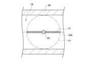
- the turbine housing 10 includes a communication passage wall 28 that defines a communication passage 18 that connects the two scroll passages 11 to each other, and a bypass passage wall 25 that defines a bypass passage 15 for directing exhaust gas flowing through the communication passage 18 to the exhaust passage 19, bypassing the turbine wheel 9.
- Both ends of the communicating passage wall 28 are connected to the communicating ports 11A (see FIG. 2) formed in the two scroll passages 11.
- an outlet 41 for guiding the exhaust gas flowing through the communicating passage 18 to the bypass passage 15 is formed in the communicating passage wall 28.
- the outlet 41 is located between the two communicating ports 11A and is located closer to the exhaust passage 19 than the turbine wheel 9. In this example, the outlet 41 penetrates the communicating passage wall 28 along the turbine radial direction.
- the turbine 5 further includes a valve device 30 configured to open and close each of the communication passage 18 and the bypass passage 15.
- the valve device 30 includes a valve rod 35 extending across the communication passage 18, a first opening and closing plate 31 attached to the valve rod 35, and a second opening and closing plate 32 attached to the valve rod 35 on the outlet 41 side of the first opening and closing plate 31. Both the first opening and closing plate 31 and the second opening and closing plate 32 are configured to rotate integrally with the valve rod 35.
- the valve rod 35 in this example has a first end 351 located on the opposite side of the communication passage 18 from the outlet 41, a second end 352 located on the outlet 41 side of the communication passage 18, and an extension 353 extending between the first end 351 and the second end 352. Both the first end 351 and the second end 352 are disposed outside the communication passage wall 28.
- the axis S of the valve rod 35 thus configured is substantially perpendicular to the communication passage center line 18A, which is the flow passage center line of the communication passage 18, and passes through the communication passage 18 and the outlet 41.
- the first opening and closing plate 31 attached to the extension portion 353 of the valve rod 35 extends along the axis S.
- the first opening and closing plate 31 is configured to open and close the communication passage 18 as the valve rod 35 rotates. More specifically, the first opening and closing plate 31 is configured to rotate between a first closed position (see FIG. 7A) in which the first opening and closing plate 31 closes the communication passage 18 in a position extending perpendicular to the communication passage center line 18A, and a first open position (see FIG. 7D) in which the first opening and closing plate 31 opens the communication passage 18 in a position extending parallel to the communication passage center line 18A. The first opening and closing plate 31 fully closes the communication passage 18 in the first closed position, and fully opens the communication passage 18 in the first open position.
- the second opening/closing plate 32 attached to the second end 352 of the valve rod 35 extends so as to intersect with the axis S, and is formed separately from the first opening/closing plate 31.
- the second opening/closing plate 32 is configured to open and close the bypass flow passage 15 in accordance with the rotation of the valve rod 35. More specifically, the second opening/closing plate 32 is configured to switch between a closed state (see FIGS. 8A and 8B) in which the bypass flow passage 15 is closed, and an open state (see FIGS. 8C and 8D) in which the bypass flow passage 15 is opened.
- FIGS. 8A and 8B a closed state in which the bypass flow passage 15 is closed
- an open state see FIGS. 8C and 8D
- the second opening/closing plate 32 extends so as to be substantially perpendicular to the axis S.
- the first opening/closing plate 31 and the second opening/closing plate 32 for opening and closing the communication passage 18 and the bypass passage 15, respectively, are constructed separately from each other, thereby realizing a turbine 5 that can freely open and close the communication passage 18 and the bypass passage 15.
- whether or not to open and close the bypass passage 15 at the timing of opening the communication passage 18 can be freely adjusted at the design stage of the turbine 5.
- the axial direction of the axis S of the valve rod 35 may be simply referred to as the "axial direction.”
- the radial direction and circumferential direction based on the axis S may be simply referred to as the "radial direction” and the “circumferential direction,” respectively.
- FIG. 4 is a schematic diagram of a valve device 30 according to an embodiment of the present disclosure
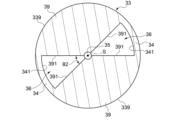
- FIG. 5 is a schematic diagram of an opposing plate 33 according to an embodiment of the present disclosure
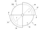
- FIG. 6 is a schematic diagram of a second opening/closing plate 32 according to an embodiment of the present disclosure.
- the turbine 5 further includes an opposing plate 33 that faces the second opening/closing plate 32 from the upstream side in the flow direction of the bypass flow passage 15.
- the opposing plate 33 formed in a circular shape is configured separately from the turbine housing 10 and is fixed to the inner surface of the turbine housing 10, for example, by welding.
- the outer peripheral surface 339 of the opposing plate 33 is fixed to the inner surface of the communicating flow passage wall 28 that defines the outlet 41.
- the opposing plate 33 also defines a passage port 36 through which the exhaust gas passes.
- the passage port 36 is a hole that is open in the axial direction.
- a pair of passage ports 36 are formed in the opposing plate 33 as openings.
- the opposing plate 33 includes a pair of main body parts 39 and a pair of connecting parts 34.
- Each of the pair of main body parts 39 formed symmetrically with respect to the axis S has a fan-shaped shape based on the axis S.
- the connecting part 34 extends in the circumferential direction and is connected to the radially outer end parts of the pair of main body parts 39.
- the passage port 36 is defined by an end face 391 in the circumferential direction of the main body part 39 and an inner peripheral surface 341 of the connecting part 34.
- the pair of passage ports 36 are arranged at equal intervals in the circumferential direction.
- Each of the passage ports 36 has a fan-shaped shape centered on the axis S.
- a valve rod 35 is inserted into a central hole formed in the center of the opposing plate 33.
- the opposing plate 33 may be formed with a single passage opening 36 as a through hole (not shown).
- the second opening and closing plate 32 has an outer peripheral surface 27 facing radially outward.
- the outer peripheral surface 27 extends parallel to the circumferential direction, and the second opening and closing plate 32 has a sector shape centered on the axis S.
- the diameter of the outer peripheral surface 27 is larger than the diameter of the inner peripheral surface 341 of the opposing plate 33.
- the maximum distance from the axis S of the valve rod 35 to the outer peripheral surface 27 is expressed as the dimension L1.
- the second opening and closing plate 32 defines an opening 29.
- the opening 29 is located in an inner region R1 of a first virtual circle 91 centered on the axis S and having a radius of the dimension L1.
- FIG. 1 the example of FIG.
- the opening 29 is defined by an end surface 321 in the circumferential direction of the second opening and closing plate 32, in other words, a plurality of second opening and closing plates 32 are arranged in the circumferential direction with the openings 29 spaced apart.
- a pair of second opening and closing plates 32 are arranged, and a pair of openings 29 are arranged at equal intervals in the circumferential direction.
- the central angle ( ⁇ 1) of the sector-shaped second opening/closing plate 32 is larger than the central angle ( ⁇ 2) of the sector-shaped passage opening 36 .
- the openings 29 may be formed as through holes in a single second opening/closing plate 32 (not shown). In this case, the openings 29 are defined by the openings formed in the second opening/closing plate 32.
- the number of openings 29 does not have to be the same as the number of passage openings 36, and the numbers of both may be different from each other.
- the second opening/closing plate 32 in this example is configured to open and close the bypass flow passage 15 by opening and closing the passage opening 36.
- the second opening/closing plate 32 is configured to rotate between a second closed position (see FIG. 8A) which is one end of the movable range and a second open position (see FIG. 8D) which is the other end of the movable range.
- a second closed position see FIG. 8A
- a second open position see FIG. 8D
- the passage opening 36 maintains a state of being closed by the second opening/closing plate 32 (see FIG. 8B).
- the opening 29 faces a part of the passage opening 36 in the axial direction (see FIG. 8C), and when the second opening/closing plate 32 reaches the second open position, the passage opening 36 is fully opened (see FIG. 8D).
- the position of the opening 29 defined by the second opening/closing plate 32 changes with the rotation of the valve rod 35, making it possible for the second opening/closing plate 32 to open and close the bypass flow passage 15.
- Whether the timing for opening and closing the communication flow passage 18 and the timing for opening and closing the bypass flow passage 15 are made to coincide or differ can be freely adjusted according to the shape of the second opening/closing plate 32, which is determined at the design stage of the turbine 5. This allows the communication flow passage 18 and the bypass flow passage 15 to be opened and closed with even more freedom.
- bypass flow passage 15 can be opened and closed simply by determining whether or not the opening 29 defined by the second opening/closing plate 32 faces the passage port 36, the structure of the valve device 30 can be simplified.
- the amount of rotation of the second opening/closing plate 32 required to open and close the bypass flow passage 15 can be reduced compared to a case in which the number of openings 29 is less than the number of passage openings 36. This allows the bypass flow passage 15 to be opened and closed quickly.
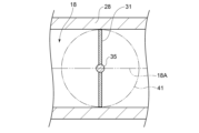
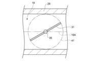
- FIGS. 7A to 7D are schematic diagrams showing an opening process of the communication flow passage 18 according to an embodiment of the present disclosure
- FIGS. 8A to 8D are schematic diagrams showing an opening process of the passage port 36 according to an embodiment of the present disclosure.
- FIGS. 7A and 8A show the state of the valve device 30 at the same time
- FIGS. 7B and 8B show the state of the valve device 30 at the same time.
- the same relationship is established between FIGS. 7C and 8C, and between FIGS. 7D and 8D.
- the radius of the second opening and closing plate 32 is illustrated to be larger than the radius of the opposing plate 33 for ease of viewing the drawings, but the second opening and closing plate 32 and the opposing plate 33 may have the same radius.
- the first opening and closing plate 31 rotates from the first open position in accordance with the rotation of the valve rod 35, and starts to open the communication flow path 18.
- the second opening and closing plate 32 also rotates from the second open position toward the second closed position, but since the central angle of the second opening and closing plate 32 is larger than the central angle of the passage port 36, the opening 29 remains shifted in the circumferential direction from the passage port 36. In other words, the second opening and closing plate 32 maintains the closed state.
- the first opening/closing plate 31 further rotates to further open the communication flow passage 18. That is, the opening of the communication flow passage 18 gradually increases. At this time, as shown in Fig.
- the opening 29 faces a part of the passage port 36 in the axial direction, and the second opening/closing plate 32 switches from the closed state to the open state.
- the communication flow path 18 is fully opened.
- the opening degree of the passage port 36 gradually increases. In other words, the opening degree of the bypass flow path 15 gradually increases.
- the opening 29 faces the entire passage port 36 in the axial direction, and the second opening/closing plate 32 fully opens the passage port 36. In other words, the bypass flow path 15 is fully opened.
- the second opening/closing plate 32 can maintain a closed state (see FIG. 8B). Furthermore, when the first opening/closing plate 31 fully opens the communication flow path 18 (see FIG. 7D), the second opening/closing plate 32 can also fully open the bypass flow path 15 (see FIG. 8D).
- the axis S of the valve rod 35 passes through an inner region R2 of the second virtual circle 92.
- the second virtual circle 92 is a virtual circle centered on the central axis C and having a diameter equal to or smaller than the outer diameter (diameter) of the turbine wheel 9.
- the diameter of the second virtual circle 92 may be, for example, 10% or more and 75% or less, or 10% or more and 50% or less of the outer diameter of the turbine wheel 9.
- the ratio may be 10% or more and 25% or less.
- the axis S in this example passes through the central axis C when viewed along the turbine axial direction.
- the two communication ports 11A (see FIG. 2) connected to both ends of the communication passage 18 are disposed at different positions in the turbine radial direction.
- the exhaust port 41 discharges the exhaust gas toward the central axis C of the turbine wheel 9, so the length of the bypass flow path 15 for guiding the exhaust gas to the exhaust flow path 19 can be shortened. This simplifies the configuration of the turbine housing 10.
- valve device 30 further includes an actuator 37 for driving the valve rod 35, and a connecting rod 38 connecting the actuator 37 to a first end 351 (see Fig. 3) of the valve rod 35.
- the actuator 37 is fixed to the compressor housing 7.
- the connecting rod 38 extends along the turbine axial direction and is configured to transmit the driving force of the actuator 37 to the valve rod 35.
- the valve rod 35 rotates in response to the driving of the actuator 37, thereby enabling the valve device 30 to open and close each of the communication passage 18 and the bypass passage 15.
- the actuator 37 is disposed in the compressor housing 7, rather than in the turbine housing 10, which is relatively prone to high temperatures, and this prevents the temperature of the actuator 37 and the connecting rod 38 from rising. This prevents the valve rod 35 from being thermally deformed, and therefore prevents the axis S of the valve rod 35 from shifting from the desired position.
- a double scroll turbine including a turbine housing (10) having two double scroll type scroll passages (11) configured to guide exhaust gas to a turbine wheel (9) and an exhaust passage (19) for exhausting the exhaust gas that has passed through the turbine wheel
- the turbine housing includes: a communication passage wall (28) defining a communication passage (18) that communicates the two scroll passages with each other; a bypass flow passage wall (25) defining a bypass flow passage (15) for directing the exhaust gas flowing through the communication flow passage to the exhaust flow passage, bypassing the turbine wheel;
- An outlet (41) is formed in the communication flow passage wall to guide the exhaust gas flowing through the communication flow passage to the bypass flow passage,
- the double scroll turbine further comprises a valve device (30);
- the valve device is A valve rod (35) extending across the communication flow passage, the axis (S) of the valve rod being provided so as to pass through the outlet;
- the first and second opening/closing plates for opening and closing the communicating passage and the bypass passage, respectively are configured separately from each other, realizing a double scroll turbine with improved freedom in opening and closing the communicating passage and the bypass passage.
- whether or not to open and close the bypass passage at the timing of opening the communicating passage can be freely adjusted at the design stage of the double scroll turbine.
- the second opening/closing plate defines an opening (29) located in an inner region (R1) of a first virtual circle (91) having a center on the axis and a radius equal to a maximum distance from the axis to an outer circumferential surface (27) of the second opening/closing plate,
- the second opening/closing plate is configured to switch, in association with rotation of the valve stem, between an open state in which the communication passage and the bypass passage are connected via the opening, and a closed state in which the bypass passage is closed.
- the position of the opening defined by the second opening/closing plate changes with the rotation of the valve stem, making it possible for the second opening/closing plate to open and close the bypass flow passage.
- Whether the timing for opening and closing the communication flow passage and the timing for opening and closing the bypass flow passage are made to coincide or differ can be freely adjusted according to the shape of the second opening/closing plate, which is determined at the design stage of the double scroll turbine. This allows the communication flow passage and the bypass flow passage to be opened and closed even more freely.
- the bypass passage is provided with an opposing plate (33) that faces the second opening/closing plate from the upstream side in the flow direction of the bypass passage and defines a passage opening (36) through which the exhaust gas passes, 3.
- the second opening/closing plate is configured to open the bypass passage by facing the opening to the passage port and to close the bypass passage by shifting the opening from the passage port.
- the configuration of 3) above provides an opposing plate that is separate from the turbine housing, making it possible to avoid making the shape of the turbine housing more complicated.
- the bypass flow path can be opened and closed simply by determining whether or not the opening defined by the second opening and closing plate faces the passage port, simplifying the configuration of the valve device.
- the double scroll turbine described in 3) above The passage openings are arranged at intervals in a circumferential direction based on the axis.
- the configuration of 4) above provides multiple passage openings, dispersing the locations through which the exhaust gas passes on the opposing plate, preventing excessive temperature rise in specific areas of the opposing plate.
- the double scroll turbine described in 4) above The plurality of passage openings are disposed at equal intervals in the circumferential direction, The openings defined by the second opening/closing plate are spaced apart in the circumferential direction and the number of the openings is the same as the number of the plurality of passage ports and are disposed at equal intervals.
- the configuration of 5) above makes it possible to reduce the amount of rotation of the second opening/closing plate required to open and close the bypass flow path, compared to when the number of openings is less than the number of passage ports. This allows the bypass flow path to be opened and closed quickly.
- the double scroll turbine according to any one of 1) to 5) above, When viewed along the axial direction of the turbine wheel (turbine axial direction), the axis of the valve rod passes through an inner region (R2) of a second imaginary circle (92) whose diameter, centered on the central axis (C) of the turbine wheel, is equal to or smaller than the outer diameter of the turbine wheel.
- a turbocharger (1) according to at least one embodiment of the present disclosure, A rotation axis (3), A double scroll turbine (5) according to any one of 1) to 5) above, including the turbine wheel (9) connected to one end (3A) of the rotating shaft; and a compressor (8) including a compressor wheel (6) connected to the other end (3B) of the rotating shaft.
- the compressor further includes a compressor housing (7) that houses the compressor wheel;
- the valve device is an actuator (37) for driving the valve stem; a connecting rod (38) connected to the actuator and the valve stem, the connecting rod being configured to transmit a driving force of the actuator to the valve stem; Further comprising:
- the actuator is disposed in the compressor housing.
- the configuration of 8) above prevents temperature rises in the actuator and connecting rod because the actuator is located in the compressor housing rather than in the turbine housing, which is prone to becoming hotter. This prevents thermal deformation of the valve rod 35, and prevents the axis of the valve rod from shifting from the desired position.
Landscapes
- Engineering & Computer Science (AREA)
- Mechanical Engineering (AREA)
- General Engineering & Computer Science (AREA)
- Chemical & Material Sciences (AREA)
- Combustion & Propulsion (AREA)
- Chemical Kinetics & Catalysis (AREA)
- General Chemical & Material Sciences (AREA)
- Supercharger (AREA)
Abstract
Description
タービンホイールに排ガスを導くように構成されたダブルスクロール型の2つのスクロール流路と、前記タービンホイールを通過した前記排ガスを排出するための排出流路とが形成されたタービンハウジングを備えるダブルスクロールタービンであって、
前記タービンハウジングは、
前記2つのスクロール流路を互いに連通させる連通流路を画定する連通流路壁と、
前記連通流路を流れる前記排ガスを、前記タービンホイールを迂回して前記排出流路に導くためのバイパス流路を画定するバイパス流路壁と
を含み、
前記連通流路壁には、前記連通流路を流れる前記排ガスを前記バイパス流路に導く導出口が形成されており、
前記ダブルスクロールタービンは、バルブ装置をさらに備え、
前記バルブ装置は、
前記連通流路を横切るように延在する弁棒であって、軸線が前記導出口を通過するように設けられる弁棒と、
前記軸線に沿って延在するように前記弁棒に取り付けられる第1開閉板であって、前記弁棒の回転に伴って前記連通流路を開閉するための第1開閉板と、
前記軸線と交差する方向に延在すると共に前記第1開閉板よりも前記導出口側で前記弁棒に取り付けられる第2開閉板であって、前記弁棒の回転に伴って前記バイパス流路を開閉するための第2開閉板と
を含む。
回転軸と、
前記回転軸の一端部に連結される前記タービンホイールを含む上記のダブルスクロールタービンと、
前記回転軸の他端部に連結されるコンプレッサホイールを含むコンプレッサと
を備える。
例えば、「ある方向に」、「ある方向に沿って」、「平行」、「直交」、「中心」、「同心」或いは「同軸」等の相対的或いは絶対的な配置を表す表現は、厳密にそのような配置を表すのみならず、公差、若しくは、同じ機能が得られる程度の角度や距離をもって相対的に変位している状態も表すものとする。
例えば、「同一」、「等しい」及び「均質」等の物事が等しい状態であることを表す表現は、厳密に等しい状態を表すのみならず、公差、若しくは、同じ機能が得られる程度の差が存在している状態も表すものとする。
例えば、四角形状や円筒形状等の形状を表す表現は、幾何学的に厳密な意味での四角形状や円筒形状等の形状を表すのみならず、同じ効果が得られる範囲で、凹凸部や面取り部等を含む形状も表すものとする。
一方、一の構成要素を「備える」、「含む」、又は、「有する」という表現は、他の構成要素の存在を除外する排他的な表現ではない。
なお、同様の構成については同じ符号を付し説明を省略することがある。
図1は、本開示の一実施形態に係るターボチャージャ1を示す概略図である。本例のターボチャージャ1は、例えば自動車に適用されてもよいエンジン12に搭載されている。ターボチャージャ1は、回転軸3と、回転軸3の一端部3Aに連結されるタービンホイール9を含むダブルスクロールタービン5と、回転軸3の他端部3Bに連結されるコンプレッサホイール6を含むコンプレッサ8とを備えている。
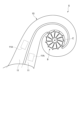
図2は、本開示の一実施形態に係るタービン5の概略図である。タービンハウジング10には、排ガスをタービンホイール9に導くための2つのスクロール流路11が形成されている。2つのスクロール流路11は、タービン軸方向において互いに同じ範囲に配置されており、なおかつ、タービン周方向において互いに異なる範囲でタービンホイール9に排ガスを供給するように構成されている。また、タービンハウジング10には、タービンホイール9を通過した排ガスを系外に排出するための排出流路19(図1参照)が形成されている。本例の排出流路19はタービン軸方向に沿って延在しており、タービンホイール9を通過した排ガスは排出流路19を経由して排気口102から排出されるようになっている。
図3に示すように、タービン5は、連通流路18とバイパス流路15の各々を開閉するように構成されたバルブ装置30をさらに備える。バルブ装置30は、連通流路18を横切るようにして延在する弁棒35と、弁棒35に取り付けられる第1開閉板31と、第1開閉板31よりも導出口41側で弁棒35に取り付けられる第2開閉板32とを含む。第1開閉板31と第2開閉板32はいずれも、弁棒35と一体的に回転するように構成されている。
図4は、本開示の一実施形態に係るバルブ装置30の概略図であり、図5は、本開示の一実施形態に係る対向板33の概略図であり、図6は本開示の一実施形態に係る第2開閉板32の概略図である。
なお、他の例では、対向板33に貫通孔としての単一の通過口36形成されていてもよい(図示外)。
なお、他の例では、単一の第2開閉板32に貫通孔としての開口29が形成されていてもよい(図示外)。この場合には、第2開閉板32に形成される開口部によって開口29が画定されることとなる。また、開口29の個数は通過口36の個数と同じでなくてもよく、両者の個数は互いに異なってもよい。
図7A~図7D、図8A~図8Dを参照し、連通流路18とバイパス流路15の各々の開閉タイミングを説明する。図7A~図7Dは、本開示の一実施形態に係る連通流路18の開放過程を示す概略図であり、図8A~図8Dは、本開示の一実施形態に係る通過口36の開放過程を示す概略図である。図7Aと図8Aは互いに同じ時点でのバルブ装置30の状態を示し、図7Bと図8Bは互いに同じ時点でのバルブ装置30の状態を示す。図7Cと図8Cの間、および、図7Dと図8Dの間においても、同様の関係が成立する。なお、図8A~図8Dでは、図面を見やすくする都合、第2開閉板32の半径が対向板33の半径よりも大きくなるよう図示しているが、第2開閉板32と対向板33は互いに同じ半径を有していてもよい。
図7B、図7Cに示すように、第1開閉板31がさらに回転して連通流路18をさらに開放する。つまり、連通流路18の開度は徐々に増大する。このとき、図8B、図8Cで示すように、開口29が通過口36の一部と軸方向に対向するようになり、第2開閉板32は閉状態から開状態に切り替わる。
図7C、図7Dに示すように、第1開閉板31がさらに回転して第1開位置に到達すると、連通流路18は全開される。このとき、図8C、図8Dで示すように、第2開閉板32は第2開位置に向けて回転するにつれて、通過口36の開度は徐々に増大する。つまり、バイパス流路15の開度は徐々に増大する。第2開閉板32が第2開位置に到達すると、開口29が通過口36の全体と軸方向に対向するようになり、第2開閉板32は通過口36を全開する。つまり、バイパス流路15は全開される。
図3に戻り本開示の幾つかの実施形態では、タービン軸方向に沿って視たとき、弁棒35の軸線Sは、第2仮想円92の内側領域R2を通過している。ここで、第2仮想円92とは、中心軸線Cを中心とした直径がタービンホイール9の外径(直径)以下となる仮想的な円である。第2仮想円92の直径は、タービンホイール9の外径に対して、例えば10%以上かつ75%以下であってもよいし、10%以上かつ50%以下であってもよいし、
10%以上かつ25%以下であってもよい。本例の軸線Sは、タービン軸方向に沿って視たとき、中心軸線Cを通過している。なお、このような構成が採用される場合、連通流路18の両端部と接続する2つの連通口11A(図2参照)は、タービン径方向において互いに異なる位置に配置されることとなる。
図1に戻り、バルブ装置30は、弁棒35を駆動するためのアクチュエータ37と、アクチュエータ37と弁棒35の第1端部351(図3参照)とを連結する連結ロッド38とをさらに含む。アクチュエータ37はコンプレッサハウジング7に固定される。連結ロッド38はタービン軸方向に沿って延在しており、アクチュエータ37の駆動力を弁棒35に伝達するように構成される。アクチュエータ37の駆動に伴い弁棒35が回転することで、バルブ装置30は連通流路18とバイパス流路15の各々を開閉することができる。
上述した幾つかの実施形態に記載の内容は、例えば以下のように把握される。
タービンホイール(9)に排ガスを導くように構成されたダブルスクロール型の2つのスクロール流路(11)と、前記タービンホイールを通過した前記排ガスを排出するための排出流路(19)とが形成されたタービンハウジング(10)を備えるダブルスクロールタービンであって、
前記タービンハウジングは、
前記2つのスクロール流路を互いに連通させる連通流路(18)を画定する連通流路壁(28)と、
前記連通流路を流れる前記排ガスを、前記タービンホイールを迂回して前記排出流路に導くためのバイパス流路(15)を画定するバイパス流路壁(25)と
を含み、
前記連通流路壁には、前記連通流路を流れる前記排ガスを前記バイパス流路に導く導出口(41)が形成されており、
前記ダブルスクロールタービンは、バルブ装置(30)をさらに備え、
前記バルブ装置は、
前記連通流路を横切るように延在する弁棒であって、軸線(S)が前記導出口を通過するように設けられる弁棒(35)と、
前記軸線に沿って延在するように前記弁棒に取り付けられる第1開閉板であって、前記弁棒の回転に伴って前記連通流路を開閉するための第1開閉板(31)と、
前記軸線と交差する方向に延在すると共に前記第1開閉板よりも前記導出口側で前記弁棒に取り付けられる第2開閉板であって、前記弁棒の回転に伴って前記バイパス流路を開閉するための第2開閉板(32)と
を含む。
前記第2開閉板は、前記軸線を中心としかつ前記軸線から前記第2開閉板の外周面(27)までの最大距離を半径とする第1仮想円(91)の内側領域(R1)に位置する開口(29)を画定しており、
前記第2開閉板は、前記開口を介して前記連通流路と前記バイパス流路とを連通させる開状態と、前記バイパス流路を閉止する閉状態との間で、前記弁棒の回転に伴い切り替わるように構成される。
前記バイパス流路の流れ方向において上流側から前記第2開閉板と対向する対向板であって、前記排ガスが通過するための通過口(36)を画定する対向板(33)をさらに備え、
前記第2開閉板は、前記開口を前記通過口に対向させることで前記バイパス流路を開放し、かつ、前記開口を前記通過口からずらすことで前記バイパス流路を閉止するように構成される
請求項2に記載のダブルスクロールタービン。
前記通過口は、前記軸線を基準とした周方向に間隔をあけて複数配置される。
前記複数の通過口は、前記周方向に等間隔に配置され、
前記第2開閉板によって画定される前記開口は、前記周方向に間隔をあけて、前記複数の通過口と同じ個数だけ等間隔に配置される。
前記タービンホイールの軸方向(タービン軸方向)に沿って視たとき、前記弁棒の前記軸線は、前記タービンホイールの中心軸線(C)を中心とした直径が前記タービンホイールの外径以下となる第2仮想円(92)の内側領域(R2)を通過する。
回転軸(3)と、
前記回転軸の一端部(3A)に連結される前記タービンホイール(9)を含む上記1)乃至5)のいずれか1項に記載のダブルスクロールタービン(5)と、
前記回転軸の他端部(3B)に連結されるコンプレッサホイール(6)を含むコンプレッサ(8)と
を備える。
前記コンプレッサは、前記コンプレッサホイールを収容するコンプレッサハウジング(7)をさらに含み、
前記バルブ装置は、
前記弁棒を駆動するためのアクチュエータ(37)と、
前記アクチュエータと前記弁棒とに連結される連結ロッドであって、前記アクチュエータの駆動力を前記弁棒に伝達するように構成される連結ロッド(38)と、
をさらに含み、
前記アクチュエータは、前記コンプレッサハウジングに配置される。
3 :回転軸
3A :一端部
3B :他端部
5 :ダブルスクロールタービン(タービン)
6 :コンプレッサホイール
7 :コンプレッサハウジング
8 :コンプレッサ
9 :タービンホイール
10 :タービンハウジング
11 :スクロール流路
15 :バイパス流路
18 :連通流路
18A :連通流路中心線
19 :排出流路
25 :バイパス流路壁
27 :外周面
28 :連通流路壁
29 :開口
30 :バルブ装置
31 :第1開閉板
32 :第2開閉板
33 :対向板
34 :連結部
35 :弁棒
36 :通過口
37 :アクチュエータ
38 :連結ロッド
39 :本体部
41 :導出口
91 :第1仮想円
92 :第2仮想円
339 :外周面
351 :第1端部
352 :第2端部
353 :延在部
C :中心軸線
L1 :寸法
R1,R2 :内側領域
Claims (8)
- タービンホイールに排ガスを導くように構成されたダブルスクロール型の2つのスクロール流路と、前記タービンホイールを通過した前記排ガスを排出するための排出流路とが形成されたタービンハウジングを備えるダブルスクロールタービンであって、
前記タービンハウジングは、
前記2つのスクロール流路を互いに連通させる連通流路を画定する連通流路壁と、
前記連通流路を流れる前記排ガスを、前記タービンホイールを迂回して前記排出流路に導くためのバイパス流路を画定するバイパス流路壁と
を含み、
前記連通流路壁には、前記連通流路を流れる前記排ガスを前記バイパス流路に導く導出口が形成されており、
前記ダブルスクロールタービンは、バルブ装置をさらに備え、
前記バルブ装置は、
前記連通流路を横切るように延在する弁棒であって、軸線が前記導出口を通過するように設けられる弁棒と、
前記軸線に沿って延在するように前記弁棒に取り付けられる第1開閉板であって、前記弁棒の回転に伴って前記連通流路を開閉するための第1開閉板と、
前記軸線と交差する方向に延在すると共に前記第1開閉板よりも前記導出口側で前記弁棒に取り付けられる第2開閉板であって、前記弁棒の回転に伴って前記バイパス流路を開閉するための第2開閉板と
を含む
ダブルスクロールタービン。 - 前記第2開閉板は、前記軸線を中心としかつ前記軸線から前記第2開閉板の外周面までの最大距離を半径とする第1仮想円の内側領域に位置する開口を画定しており、
前記第2開閉板は、前記開口を介して前記連通流路と前記バイパス流路とを連通させる開状態と、前記バイパス流路を閉止する閉状態との間で、前記弁棒の回転に伴い切り替わるように構成される。
請求項1に記載のダブルスクロールタービン。 - 前記バイパス流路の流れ方向において上流側から前記第2開閉板と対向する対向板であって、前記排ガスが通過するための通過口を画定する対向板をさらに備え、
前記第2開閉板は、前記開口を前記通過口に対向させることで前記バイパス流路を開放し、かつ、前記開口を前記通過口からずらすことで前記バイパス流路を閉止するように構成される
請求項2に記載のダブルスクロールタービン。 - 前記通過口は、前記軸線を基準とした周方向に間隔をあけて複数配置される
請求項3に記載のダブルスクロールタービン。 - 前記複数の通過口は、前記周方向に等間隔に配置され、
前記第2開閉板によって画定される前記開口は、前記周方向に間隔をあけて、前記複数の通過口と同じ個数だけ等間隔に配置される
請求項4に記載のダブルスクロールタービン。 - 前記タービンホイールの軸方向に沿って視たとき、前記弁棒の前記軸線は、前記タービンホイールの中心軸線を中心とした直径が前記タービンホイールの外径以下となる第2仮想円の内側領域を通過する
請求項1乃至3の何れか1項に記載のダブルスクロールタービン。 - 回転軸と、
前記回転軸の一端部に連結される前記タービンホイールを含む請求項1乃至3のいずれか1項に記載のダブルスクロールタービンと、
前記回転軸の他端部に連結されるコンプレッサホイールを含むコンプレッサと
を備えるターボチャージャ。 - 前記コンプレッサは、前記コンプレッサホイールを収容するコンプレッサハウジングをさらに含み、
前記バルブ装置は、
前記弁棒を駆動するためのアクチュエータと、
前記アクチュエータと前記弁棒とに連結される連結ロッドであって、前記アクチュエータの駆動力を前記弁棒に伝達するように構成される連結ロッドと、
をさらに含み、
前記アクチュエータは、前記コンプレッサハウジングに配置される
請求項7に記載のターボチャージャ。
Priority Applications (4)
| Application Number | Priority Date | Filing Date | Title |
|---|---|---|---|
| JP2025509577A JPWO2024201989A1 (ja) | 2023-03-31 | 2023-03-31 | |
| CN202380096000.3A CN120813756A (zh) | 2023-03-31 | 2023-03-31 | 双螺旋涡轮机及涡轮增压器 |
| DE112023005632.3T DE112023005632T5 (de) | 2023-03-31 | 2023-03-31 | Doppelschnecken-turbine und turbolader |
| PCT/JP2023/013507 WO2024201989A1 (ja) | 2023-03-31 | 2023-03-31 | ダブルスクロールタービン、および、ターボチャージャ |
Applications Claiming Priority (1)
| Application Number | Priority Date | Filing Date | Title |
|---|---|---|---|
| PCT/JP2023/013507 WO2024201989A1 (ja) | 2023-03-31 | 2023-03-31 | ダブルスクロールタービン、および、ターボチャージャ |
Publications (1)
| Publication Number | Publication Date |
|---|---|
| WO2024201989A1 true WO2024201989A1 (ja) | 2024-10-03 |
Family
ID=92904493
Family Applications (1)
| Application Number | Title | Priority Date | Filing Date |
|---|---|---|---|
| PCT/JP2023/013507 Ceased WO2024201989A1 (ja) | 2023-03-31 | 2023-03-31 | ダブルスクロールタービン、および、ターボチャージャ |
Country Status (4)
| Country | Link |
|---|---|
| JP (1) | JPWO2024201989A1 (ja) |
| CN (1) | CN120813756A (ja) |
| DE (1) | DE112023005632T5 (ja) |
| WO (1) | WO2024201989A1 (ja) |
Citations (4)
| Publication number | Priority date | Publication date | Assignee | Title |
|---|---|---|---|---|
| JP2017537259A (ja) * | 2014-12-12 | 2017-12-14 | ボーグワーナー インコーポレーテッド | バイパス弁及び流れ連結用組み合わせ型の調整装置を備えた排気ガスターボチャージャー |
| US20200263598A1 (en) * | 2019-02-15 | 2020-08-20 | Borgwarner Inc. | Method of controlling a valve of a dual volute turbocharger |
| JP2020143623A (ja) * | 2019-03-06 | 2020-09-10 | ボーグワーナー インコーポレーテッド | 多流式タービン用タービンハウジング |
| US20200318530A1 (en) * | 2016-05-12 | 2020-10-08 | Continental Automotive Gmbh | Turbine for an exhaust turbocharger having a two-channel turbine housing and a valve for channel connection |
-
2023
- 2023-03-31 WO PCT/JP2023/013507 patent/WO2024201989A1/ja not_active Ceased
- 2023-03-31 CN CN202380096000.3A patent/CN120813756A/zh active Pending
- 2023-03-31 DE DE112023005632.3T patent/DE112023005632T5/de active Pending
- 2023-03-31 JP JP2025509577A patent/JPWO2024201989A1/ja active Pending
Patent Citations (4)
| Publication number | Priority date | Publication date | Assignee | Title |
|---|---|---|---|---|
| JP2017537259A (ja) * | 2014-12-12 | 2017-12-14 | ボーグワーナー インコーポレーテッド | バイパス弁及び流れ連結用組み合わせ型の調整装置を備えた排気ガスターボチャージャー |
| US20200318530A1 (en) * | 2016-05-12 | 2020-10-08 | Continental Automotive Gmbh | Turbine for an exhaust turbocharger having a two-channel turbine housing and a valve for channel connection |
| US20200263598A1 (en) * | 2019-02-15 | 2020-08-20 | Borgwarner Inc. | Method of controlling a valve of a dual volute turbocharger |
| JP2020143623A (ja) * | 2019-03-06 | 2020-09-10 | ボーグワーナー インコーポレーテッド | 多流式タービン用タービンハウジング |
Also Published As
| Publication number | Publication date |
|---|---|
| DE112023005632T5 (de) | 2025-11-13 |
| CN120813756A (zh) | 2025-10-17 |
| JPWO2024201989A1 (ja) | 2024-10-03 |
Similar Documents
| Publication | Publication Date | Title |
|---|---|---|
| JP6542246B2 (ja) | 可変容量型過給機 | |
| JP3725287B2 (ja) | 可変容量ターボチャージャ | |
| CN102536434B (zh) | 具有涡轮的分开涡轮壳体和环形旋转旁通阀的涡轮增压器 | |
| JP5710452B2 (ja) | ターボチャージャ | |
| US20040244373A1 (en) | Controlled turbocharger with integrated bypass | |
| JP4797788B2 (ja) | ターボチャージャ | |
| JP7227050B2 (ja) | 制御バルブ | |
| US9028202B2 (en) | Variable geometry turbine | |
| JP4005025B2 (ja) | 一体化されたバイパスを備えた被制御ターボ過給機 | |
| JP6152049B2 (ja) | 可変ノズルユニット及び可変容量型過給機 | |
| JP7635844B2 (ja) | タービン及び過給機 | |
| WO2024201989A1 (ja) | ダブルスクロールタービン、および、ターボチャージャ | |
| JP7196994B2 (ja) | 可変容量型過給機 | |
| JP2005330973A (ja) | 可変容量ターボチャージャ | |
| JP7302738B2 (ja) | 可変容量型過給機 | |
| JPH03182628A (ja) | 内燃機関用の圧力交換器 | |
| CN114517732B (zh) | 涡轮增压器 | |
| US20260063041A1 (en) | Turbine and turbocharger | |
| JP2021161870A (ja) | 可変容量型過給機 | |
| WO2020050052A1 (ja) | 斜流タービンおよび過給機 | |
| JP2014169643A (ja) | 可変容量型過給機 | |
| WO2024201987A1 (ja) | 可変ノズル装置、および可変容量型排気ターボ過給機 | |
| JP2017025888A (ja) | ターボチャージャ | |
| JP2025059499A (ja) | ターボチャージャ | |
| WO2023139639A1 (ja) | 可変容量タービン及びこれを備えるターボチャージャー |
Legal Events
| Date | Code | Title | Description |
|---|---|---|---|
| 121 | Ep: the epo has been informed by wipo that ep was designated in this application |
Ref document number: 23930624 Country of ref document: EP Kind code of ref document: A1 |
|
| ENP | Entry into the national phase |
Ref document number: 2025509577 Country of ref document: JP Kind code of ref document: A |
|
| WWE | Wipo information: entry into national phase |
Ref document number: 2025509577 Country of ref document: JP |
|
| WWE | Wipo information: entry into national phase |
Ref document number: 112023005632 Country of ref document: DE Ref document number: 202380096000.3 Country of ref document: CN |
|
| WWP | Wipo information: published in national office |
Ref document number: 202380096000.3 Country of ref document: CN |
|
| 122 | Ep: pct application non-entry in european phase |
Ref document number: 23930624 Country of ref document: EP Kind code of ref document: A1 |