WO2024201871A1 - 車両構造 - Google Patents
車両構造 Download PDFInfo
- Publication number
- WO2024201871A1 WO2024201871A1 PCT/JP2023/013094 JP2023013094W WO2024201871A1 WO 2024201871 A1 WO2024201871 A1 WO 2024201871A1 JP 2023013094 W JP2023013094 W JP 2023013094W WO 2024201871 A1 WO2024201871 A1 WO 2024201871A1
- Authority
- WO
- WIPO (PCT)
- Prior art keywords
- vehicle
- base
- control unit
- electronic control
- width direction
- Prior art date
- Legal status (The legal status is an assumption and is not a legal conclusion. Google has not performed a legal analysis and makes no representation as to the accuracy of the status listed.)
- Ceased
Links
Images


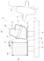







Classifications
-
- B—PERFORMING OPERATIONS; TRANSPORTING
- B62—LAND VEHICLES FOR TRAVELLING OTHERWISE THAN ON RAILS
- B62D—MOTOR VEHICLES; TRAILERS
- B62D25/00—Superstructure or monocoque structure sub-units; Parts or details thereof not otherwise provided for
- B62D25/08—Front or rear portions
-
- B—PERFORMING OPERATIONS; TRANSPORTING
- B62—LAND VEHICLES FOR TRAVELLING OTHERWISE THAN ON RAILS
- B62D—MOTOR VEHICLES; TRAILERS
- B62D25/00—Superstructure or monocoque structure sub-units; Parts or details thereof not otherwise provided for
- B62D25/20—Floors or bottom sub-units
Definitions
- the present invention relates to a vehicle structure.
- Patent Document 1 shows a mounting structure in which, in the event of a vehicle collision, the base plate portion of the mounting bracket to which the ECU is attached receives an upward force from the assist piece portion, and this upward force causes the mounting piece portion to move upward while bending in an approximately L-shape starting from a triangular fold bead.
- the ECU fixed to the base plate portion moves upward, avoiding interference between the ECU and the reversing transmission.
- the present invention aims to provide a vehicle structure that can effectively protect the electronic control unit while keeping costs down.
- the present invention comprises the following configurations.
- a first in-vehicle device an electronic control unit disposed rearward in a vehicle front-rear direction with respect to the first vehicle-mounted device and at least a portion of the electronic control unit disposed in a position shifted in a vehicle width direction; a base that is attached to a vehicle body with the first on-board device and the electronic control unit placed thereon; Equipped with Vehicle structure.
- the present invention provides a vehicle structure that effectively protects the electronic control unit while keeping costs down.
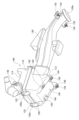
- FIG. 1 is a schematic plan view of the front part of a vehicle to which a vehicle structure according to an embodiment of the present invention is applied.
- FIG. 2 is a schematic plan view showing the positional relationship of on-vehicle components.
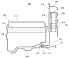
- FIG. 3 is a cross-sectional view taken along line III-III in FIG.
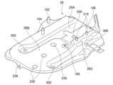
- FIG. 4 is a perspective view of the base.
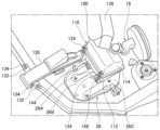
- FIG. 5 is a perspective view of the air cleaner mounted on the base as viewed from the front side of the vehicle.
- FIG. 6 is a perspective view of the air cleaner mounted on the base as viewed from the rear side of the vehicle.
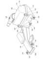
- FIG. 7 is a perspective view of the air cleaner.
- FIG. 8 is a perspective view of the air cleaner as viewed from below.
- FIG. 9 is a side view of the air cleaner.
- FIG. 1 is a schematic plan view of the front part of a vehicle to which a vehicle structure according to an embodiment of the present invention is applied.
- FIG. 2 is a schematic plan view showing the positional
- FIG. 10 is a perspective view of the battery mounted on the base as viewed from the front side of the vehicle.
- FIG. 11 is a perspective view of the battery mounted on the base as viewed from the rear side of the vehicle.
- FIG. 12 is a perspective view of the tray as seen from below.
- FIG. 13 is a perspective view of the electronic control unit mounted on the base.
- FIG. 14 is a perspective view of the electronic control unit mounted on the base as viewed from the outside in the vehicle width direction.
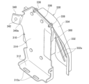
- FIG. 15 is a perspective view of the electronic control unit mounted on the mounting bracket.
- FIG. 16 is an exploded perspective view illustrating the mounting structure of the electronic control unit to the mounting bracket.
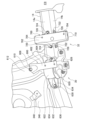
- FIG. 17 is a cross-sectional view taken along line XVII-XVII in FIG. FIG.
- FIG. 18 is a perspective view illustrating the mounting structure of the mounting bracket to the strut receiving portion.
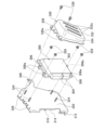
- FIG. 19 is a perspective view of the base attached to the side frame.
- FIG. 20 is an exploded perspective view showing the mounting structure of the base to the side frame.
- FIG. 21 is a perspective view of a first fixing member and a second fixing member that support the base.
- FIG. 22 is a perspective view of a first fixing member and a second fixing member that support the base.
- FIG. 23 is a perspective view of the first fixing member as viewed from one side in the vehicle width direction.
- FIG. 24 is a perspective view of the first fixing member as viewed from the other side in the vehicle width direction.
- FIG. 25 is a perspective view of the second fixing member as viewed from one side in the vehicle width direction.
- FIG. 26 is a perspective view of the second fixing member as viewed from the other side in the vehicle width direction.
- Fig. 1 is a schematic plan view of the front of a vehicle 10 to which a vehicle structure according to an embodiment of the present invention is applied.
- Fig. 2 is a schematic plan view showing the positional relationship of on-vehicle parts.
- Fig. 3 is a cross-sectional view taken along line III-III in Fig. 2.
- the vehicle structure according to this embodiment is applied to the internal structure of an engine room 12 provided at the front of a vehicle 10.
- an air cleaner (second on-board device) 100, a battery (first on-board device) 200, and an electronic control unit (ECU: Electronic Control Unit) 300 are arranged on one side in the vehicle width direction.
- the battery 200 is disposed forward of the air cleaner 100 in the vehicle's fore-and-aft direction.
- the electronic control unit 300 is disposed rearward of the battery 200 in the vehicle's fore-and-aft direction, and is further disposed at a position offset in the vehicle width direction from the battery 200. As a result, the electronic control unit 300 is disposed to the side of the air cleaner 100 in the vehicle width direction.
- the air cleaner 100, the battery 200, and the electronic control unit (ECU) 300 are disposed on top of a single base 26.
- the air cleaner 100, the battery 200, and the electronic control unit (ECU) 300 are mounted on a single base 26 and supported from below by this base 26.
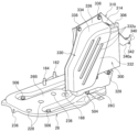
- FIG. 4 is a perspective view of the base 26.
- the base 26 has an air cleaner mounting portion 26A, a battery mounting portion 26B, and an ECU mounting portion 26C.
- the air cleaner 100 is mounted in the air cleaner mounting portion 26A
- the battery 200 is mounted in the battery mounting portion 26B
- the electronic control unit 300 is mounted in the ECU mounting portion 26C.
- the base 26 is attached to a side frame 14 that constitutes the chassis frame (vehicle body) of the vehicle 10 (see Figure 3).
- the chassis frame has a pair of side frames 14 that extend in the fore-and-aft direction of the vehicle and are spaced apart in the vehicle width direction, and these side frames 14 are connected to each other at multiple points spaced apart in the vehicle fore-and-aft direction by multiple cross members (not shown) that extend in the vehicle width direction.
- the base 26 is attached to one of the pair of side frames 14 (the left side) in the vehicle width direction in the engine compartment 12 at the front of the vehicle.
- the base 26 is attached to one of the side frames 14 by a first fixing member 30 and a second fixing member 32.
- the first fixing member 30 is disposed directly below the air cleaner 100 mounted on the air cleaner mounting portion 26A of the base 26, and the second fixing member 32 is disposed directly below the battery 200 mounted on the battery mounting portion 26B of the base 26.
- a master cylinder 16 is provided on the wall surface 12a on the passenger compartment side that constitutes the engine room 12. This master cylinder 16 is disposed rearward of the air cleaner 100 in the vehicle longitudinal direction. In other words, the air cleaner 100 and the battery 200 mounted on a base 26 are disposed in this order forward of the master cylinder 16 in the vehicle longitudinal direction. This master cylinder 16 is disposed rearward of the lower part of the air cleaner 100 in the vehicle longitudinal direction.
- FIG. 5 is a perspective view of the air cleaner 100 mounted on the base 26 as viewed from the vehicle front side.
- Fig. 6 is a perspective view of the air cleaner 100 mounted on the base 26 as viewed from the vehicle rear side.
- Fig. 7 is a perspective view of the air cleaner 100.
- Fig. 8 is a perspective view of the air cleaner 100 as viewed from below.
- Fig. 9 is a side view of the air cleaner 100.
- the air cleaner 100 is attached to the air cleaner mounting portion 26A of the base 26.
- the air cleaner 100 has a resin case 110.
- This case 110 is box-shaped and made up of a lower case 112 and an upper case 114.
- the case 110 has a filter 116 in its internal space, which divides the internal space of the case 110 into upper and lower sections (see Figure 3).
- the lower case 112 is provided with locking pieces 120 having locking holes 120a at two locations on its rear surface.
- the upper case 114 is provided with locking protrusions 122 at two locations on its rear surface.
- the upper case 114 is attached to cover the upper part of the lower case 112 by inserting the locking protrusions 122 into the locking holes 120a of the locking pieces 120 of the lower case 112 and placing it over the lower case 112.
- the lower case 112 and the upper case 114 also have locking portions 124 at two locations on their front surfaces.
- One end of a clip 126 is connected to the locking portion 124 on the lower case 112 side.
- the clip 126 is formed from an elastic metal plate, and the other free end can be locked to the upper case 114 side. In other words, by rotating this clip 126 and engaging the free end with the upper case 114, the upper case 114 is maintained in an assembled state with the lower case 112.
- the air cleaner 100 is equipped with an intake duct 130.
- the intake duct 130 is connected to the front side of the lower case 112.
- the intake duct 130 is connected to the lower case 112 at a position closer to the inside in the vehicle width direction, that is, at a position closer to the engine side opposite the outside in the vehicle width direction.
- the intake duct 130 extends forward in the vehicle front-rear direction.
- the intake duct 130 has a connection part 132 at its tip, and this connection part 132 is fastened and fixed to the vehicle body by a bolt 134.
- the air cleaner 100 also includes a connecting duct (duct) 136.
- the connecting duct 136 is connected to an inner corner in the vehicle width direction on the rear surface of the upper case 114. This connecting duct 136 extends in the vehicle width direction and is connected to the engine (not shown).
- air is drawn in through the intake port 130a at the end of the intake duct 130.
- the air drawn into the intake duct 130 passes through a filter 116 provided in the internal space of the case 110, and is then sent to the engine via the connecting duct 136. Note that even if water is drawn into the intake duct 130 along with the air, this water collects at the bottom of the lower case 112 of the air cleaner 100 and is not sent to the engine.
- the underside of the air cleaner 100 is the mounting portion 140, which is attached to the air cleaner mounting portion 26A of the base 26.
- the mounting portion 140 has engagement portions 142, 144, an abutment portion 146, and a fastening portion 148.
- the engagement portions 142, 144 are disposed on the inside of the vehicle width direction, which is the engine side of the air cleaner 100, and the abutment portion 146 and the fastening portion 148 are disposed on the outside of the vehicle width direction, which is the opposite side of the air cleaner 100 from the engine side.
- the engagement parts 142, 144 are provided with bushings 150 made of, for example, rubber or plastic.
- a buffer plate 152 made of, for example, a rubber sheet is attached to the abutment part 146.
- a bolt 154 is provided to the fastening part 148.
- Pins 162, 164 are erected on the air cleaner mounting portion 26A of the base 26 at positions corresponding to the engagement portions 142, 144, a smooth abutment surface 166 is provided at a position corresponding to the abutment portion 146, and a bolt hole 168 is provided at a position corresponding to the fastening portion 148 (see Figure 4).
- the air cleaner 100 is placed from above on the air cleaner mounting portion 26A of the base 26.
- the pins 162, 164 are inserted into and engaged with the bushings 150 of the engagement portions 142, 144, and the buffer plate 152 of the abutment portion 146 abuts against the abutment surface 166.
- the bolts 154 of the fastening portions 148 are screwed into the bolt holes 168 of the base 26 and fastened, whereby the air cleaner 100 is attached to the air cleaner mounting portion 26A of the base 26.
- the air cleaner 100 is engaged with the base 26 by the pins 162, 164 and the bush 150 on the inside in the vehicle width direction, which is the engine side. Furthermore, on the outside in the vehicle width direction, which is the opposite side to the engine side, the abutment portion 146 of the air cleaner 100 is abutted against the abutment surface 166 of the base 26 on the rear side in the vehicle longitudinal direction, and the fastening portion 148 is fastened to the base 26 by the bolt 154 on the front side in the vehicle longitudinal direction, and is firmly fixed.
- the air cleaner 100 is attached to the base 26 at its mounting portion 140 so that the engine side in the vehicle width direction can displace in response to external forces from the engine. Therefore, the mounting portion 140 of the air cleaner 100 on the base 26 can absorb external forces associated with engine roll and the like that are transmitted to the air cleaner 100 through the connecting duct 136.
- the case 110 is inclined toward the rear in the vehicle's fore-and-aft direction toward the top of the vehicle, and the filter 116 is disposed inside the case 110 with the rear side in the vehicle's fore-and-aft direction inclined downward (see FIG. 3). Therefore, the direction of the air flow sucked in from the front side in the vehicle's fore-and-aft direction through the intake duct 130 is gently changed and passed through the filter 116. This reduces the loss of air pressure in the air cleaner 100.
- a large space S1 can be secured between the air cleaner 100 and the master cylinder 16 arranged at the rear of the lower part of the air cleaner 100 in the vehicle longitudinal direction. This makes it possible to more effectively prevent contact between the air cleaner 100 and the master cylinder 16 arranged at the rear side of the air cleaner 100 in the vehicle longitudinal direction.
- a large space S2 can be secured above the air cleaner 100 and the battery 200.
- the fastening portion 148 of the air cleaner 100 is positioned so that it overlaps with the space S2 between the air cleaner 100 and the battery 200 when viewed from the top-bottom direction of the vehicle, so that the fastening portion 148 of the air cleaner 100 can be easily fastened to the base 26 by passing a tool through the space S2 and using the bolt 154.
- the case 110 of the air cleaner 100 is inclined rearward in the vehicle front-rear direction toward the top of the vehicle, when an external force caused by engine roll is transmitted to the air cleaner 100 through the connecting duct 136, the external force can be applied evenly to the upper part of the case 110. This makes it possible to prevent the opening at the joint between the lower case 112 and the upper case 114.
- Fig. 10 is a perspective view of the battery 200 mounted on the base 26 as viewed from the front side of the vehicle.
- Fig. 11 is a perspective view of the battery 200 mounted on the base 26 as viewed from the rear side of the vehicle.
- Fig. 12 is a perspective view of the tray 220 as viewed from below.
- the battery 200 is attached to the battery mounting portion 26B of the base 26.
- the battery 200 has a rectangular parallelepiped shape and has negative and positive terminals 212 on its top surface 210.
- the battery 200 When attached to the battery mounting section 26B of the base 26, the battery 200 is arranged with its front surface 214 and rear surface 216 facing forward and backward in the vehicle longitudinal direction, and both side surfaces 218 facing in the vehicle width direction.
- the battery 200 is attached to the battery mounting section 26B of the base 26 while placed on a tray 220.
- the tray 220 has a rectangular bottom surface 222 and a peripheral wall 224 standing upward from the outer edge of the bottom surface 222.
- the bottom of the battery 200 is fitted into the tray 220 from above.
- the tray 220 has two positioning protrusions 226 on its bottom surface, which fit into positioning holes 228 formed in the battery mounting portion 26B of the base 26 (see FIG. 4). As a result, the battery 200 mounted on the tray 220 is positioned in the battery mounting portion 26B of the base 26.
- the battery 200 is fixed to the base 26 by a stay 230 and a rod 232.
- the stay 230 is provided with a pressure plate portion 230a having holes (not shown) at both ends.
- the rod 232 is a rod body with a male thread formed on one end, and a hook 234 formed by bending the rod body is provided at the other end of the rod 232.
- a locking hole 236 is formed in the battery mounting portion 26B of the base 26, and the hook 234 of the rod 232 can be locked into the locking hole 236.
- the battery 200 is placed on the tray 220, which is positioned and placed on the battery mounting section 26B of the base 26. With the battery 200 placed on the battery mounting section 26B, the hooks 234 of the rods 232 are engaged with the engagement holes 236 of the base 26. One end of each of these rods 232 is then passed through the hole in the pressure plate section 230a of the stay 230, and the nut 238 is screwed onto one end of the rod 232 to fasten them together. As a result, the battery 200 is attached to the battery mounting section 26B of the base 26 while being pressed against the base 26 by the stay 230 and the rod 232.
- FIG. 13 is a perspective view of the electronic control unit 300 mounted on the pedestal 26.
- Fig. 14 is a perspective view of the electronic control unit 300 mounted on the pedestal 26, as viewed from the outside in the vehicle width direction.
- Fig. 15 is a perspective view of the electronic control unit 300 mounted on the mounting bracket 310.
- Fig. 16 is an exploded perspective view illustrating the mounting structure of the electronic control unit 300 to the mounting bracket 310.
- Fig. 17 is a cross-sectional view taken along line XVII-XVII in Fig. 2.
- Fig. 18 is a perspective view illustrating the mounting structure of the mounting bracket 310 to the strut housing portion 346.
- the electronic control unit 300 is mounted on the ECU mounting portion 26C of the base 26.
- the electronic control unit 300 is fixed to a mounting bracket 310, and is attached to the ECU mounting portion 26C of the base 26 by the mounting bracket 310.
- the mounting bracket 310 has a bottom portion 312 and a side portion 314, and the electronic control unit 300 is fixed to the side portion 314.
- the side portion 314 is bent upward from one side edge of the bottom portion 312 and stands upright, so that the mounting bracket 310 is formed into a roughly L-shape.
- the bottom portion 312 of the mounting bracket 310 is fixed to the base 26. Then, by fixing the bottom portion 312 to the base 26, the side portion 314 is positioned along the fore-and-aft direction of the vehicle.
- the mounting bracket 310 has a mounting surface 320 on the side 314 opposite the extension direction of the bottom 312, and the electronic control unit 300 is fixed to this mounting surface 320.
- a protective bracket 330 that protects the electronic control unit 300 is attached to the mounting surface 320 of this side 314.
- a number of stud bolts 324 are provided on the mounting surface 320 of the mounting bracket 310.
- a number of screw holes 326 are provided on the upper edge of the side portion 314 of the mounting bracket 310.
- the electronic control unit 300 has a unit body 302 and a connector portion 304.
- the connector portion 304 is provided on the front side of the unit body 302 in the vehicle front-rear direction.
- a connector (not shown) of a wire harness is connected to the connector portion 304.
- the unit body 302 is provided with a mounting flange 306 having multiple mounting holes 306a on its upper and lower edges.
- the electronic control unit 300 is placed on the mounting surface 320 of the side portion 314 by inserting the stud bolt 324 through the mounting hole 306a. In this state, the nut 328 is screwed onto the stud bolt 324 and tightened, thereby fixing the electronic control unit 300 to the side portion 314 of the mounting bracket 310.
- the protective bracket 330 is attached to the side portion 314 of the mounting bracket 310 so as to cover the electronic control unit 300 fixed to the side portion 314.
- This protective bracket 330 has a flat plate portion 332 and a side plate portion 334 that protrudes from the flat plate portion 332 towards the side portion 314.
- the side plate portion 334 is provided on the front side in the longitudinal direction of the vehicle and on the upper side of the vehicle.
- a flange portion 336 is formed on the edge of the side plate portion 334, and a plurality of holes 336a are formed on the upper side of the vehicle in this flange portion 336.
- This protective bracket 330 is placed against the side 314 of the mounting bracket 310 so as to cover the electronic control unit 300 fixed to the side 314. In this state, the protective bracket 330 is attached to the side 314 of the mounting bracket 310 by inserting the mounting screw 338 into the hole 336a and screwing it into the screw hole 326 and tightening it.
- the electronic control unit 300 fixed to the side 314 of the mounting bracket 310 is covered by the protective bracket 330 on the outer side in the vehicle width direction, the front side in the vehicle fore-and-aft direction, and the upper side of the vehicle.
- the protective bracket 330 may also be provided with side plate portions 334 on the rear side in the vehicle longitudinal direction and on the lower side of the vehicle. In this way, the entire periphery of the electronic control unit 300 fixed to the side portion 314 of the mounting bracket 310 can be covered and protected.
- the flat plate portion 332 of the protective bracket 330 has multiple ventilation holes 332a formed therein, ensuring good heat dissipation from the electronic control unit 300.
- the bottom 312 of the mounting bracket 310 has two mounting holes 312a aligned along the vehicle's fore-and-aft direction.
- Each of these mounting holes 312a is an elongated hole extending in the vehicle's fore-and-aft direction.
- Two stud bolts (bolts) 316 that can be inserted into the mounting holes 312a of the bottom 312 are arranged in the vehicle's fore-and-aft direction and stand upright on the ECU mounting portion 26C of the base 26 (see Figure 4).
- the mounting bracket 310 is fixed to the ECU mounting portion 26C of the base 26 by inserting the stud bolt 316 of the base 26 into the mounting hole 312a of the bottom 312 and then screwing and tightening the nut 318 onto the stud bolt 316.
- the mounting bracket 310 to which the electronic control unit 300 is fixed on the side portion 314, to the base 26, the electronic control unit 300 and the side portion 314 of the mounting bracket 310 are positioned along the vehicle front-rear direction on the outer side of the air cleaner 100 in the vehicle width direction.
- the electronic control unit 300 and the mounting bracket 310 are disposed rearward of the battery 200 in the vehicle longitudinal direction and outward in the vehicle width direction.
- the mounting bracket 310 and the electronic control unit 300 mounted on the mounting bracket 310 are disposed on the left side of the vehicle 10, which is outward in the vehicle width direction from a line SL that extends in the vehicle longitudinal direction along one side surface 218 of the battery 200 mounted on the base 26 in the vehicle width direction.
- the electronic control unit 300 may be disposed in a position where a part of it is shifted in the vehicle width direction relative to the battery 200. By adopting such a positional relationship, it is possible to prevent the battery 200 from coming into contact with the electronic control unit 300 even if the battery 200 is displaced rearward in the vehicle longitudinal direction during a vehicle collision or the like.
- the electronic control unit 300 mounted on the base 26 is positioned on the outer side (one end side) in the vehicle width direction, and is positioned adjacent to the air cleaner 100 in the vehicle width direction.
- the air cleaner 100 is positioned between the electronic control unit 300 and a power unit such as an engine or motor that is positioned in the center of the vehicle 10 in the vehicle width direction.
- the bottom 312 of the mounting bracket 310 is positioned between the base 26 and the air cleaner 100.
- the mounting bracket 310 has an extension 340 provided on its side 314.
- This extension 340 is provided on the rear edge of the side 314 in the vehicle longitudinal direction, and is formed integrally with the side 314.
- This extension 340 has a fastening hole 342 (see Figure 15).
- this extension 340 has a bent portion 340a formed midway in the extension direction. As a result, the extension direction of the extension 340 is changed at the bent portion 340a midway.
- This extension 340 is fixed to a fastening portion 348 provided in a strut housing portion 346 that covers the strut on the front wheel side of the body of the vehicle 10.
- the extension 340 is fixed to the strut housing portion 346 by fastening a bolt 344 passed through a fastening hole 342 to the fastening portion 348.
- FIG. 19 is a perspective view of the base 26 attached to the side frame 14.
- FIG. 20 is an exploded perspective view showing the mounting structure of the base 26 to the side frame 14.
- FIG. 21 is a perspective view of the first fixing member 30 and the second fixing member 32 that support the base 26.
- FIG. 22 is a perspective view of the first fixing member 30 and the second fixing member 32 that support the base 26.
- FIG. 23 is a perspective view of the first fixing member 30 as viewed from one side in the vehicle width direction.
- FIG. 24 is a perspective view of the first fixing member 30 as viewed from the other side in the vehicle width direction.
- FIG. 25 is a perspective view of the second fixing member 32 as viewed from one side in the vehicle width direction.
- FIG. 26 is a perspective view of the second fixing member 32 as viewed from the other side in the vehicle width direction.
- the base 26 is disposed above the side frame 14 on the outer side (one end side) in the vehicle width direction, and is fixed to the side frame 14 by a first fixing member 30 and a second fixing member 32.
- first fixing member 30 and second fixing member 32 are fixed to the side frame 14.
- the first fixing member 30 is disposed directly below the air cleaner 100 mounted on the air cleaner mounting portion 26A of the base 26
- the second fixing member 32 is disposed directly below the battery 200 mounted on the battery mounting portion 26B of the base 26.
- the first fixing member 30 has higher rigidity than the second fixing member 32.
- the base 26 has a pair of insertion holes 500 on the rear side in the vehicle's fore-and-aft direction, and a pair of insertion holes 502 on the front side in the vehicle's fore-and-aft direction (see FIG. 20).
- a bolt 504 is inserted into the insertion holes 500 and fastened to the first fixing member 30. This fixes the rear side of the base 26 in the vehicle's fore-and-aft direction to the first fixing member 30.
- a bolt 506 is inserted into the insertion holes 502 and fastened to the second fixing member 32. This fixes the front side of the base 26 in the vehicle's fore-and-aft direction to the second fixing member 32.
- the first fixing member 30 has a first bracket 600.
- the first bracket 600 has a fixing plate portion 602 extending in the vehicle width direction.
- the fixing plate portion 602 has a bolt hole 604 into which the bolt 504 is screwed.
- the fixing plate portion 602 has both edges protruding downward to form a U-shape in cross section.
- a joint piece portion 606 extending downward is formed on one edge of the fixing plate portion 602.
- the first bracket 600 has a connection portion 608 at one end.
- the connection portion 608 is fastened and fixed to an inner portion of a fender panel 612 of the vehicle 10 by a bolt 610.
- the base 26 is connected to the fender panel 612 of the vehicle 10 by the first bracket 600 of the first fixing member 30.
- This first bracket 600 is located below the electronic control unit 300, which is mounted on the base 26 adjacent to the air cleaner 100.
- the first fixing member 30 also has a mount member 620 that supports the first bracket 600 from below.
- This mount member 620 is, for example, a mount that supports a power unit such as an engine or a motor on the side frame 14.
- the mount member 620 has a mount body 622.
- the mount body 622 is formed in a cylindrical shape, and an elastic body 624 is housed inside.
- a pin 628 extending from a fixing seat 626 that is fixed to the engine or motor is inserted into the center of the elastic body 624.
- the cylindrical mount body 622 is a highly rigid member, and the underside of the first bracket 600 and the joint piece 606 are welded and firmly fixed to the circumferential surface of this mount body 622.
- the mount member 620 also has a fixed bracket 630.
- the fixed bracket 630 has a bottom surface portion 632 extending in the front-rear direction of the vehicle, and a pair of side surfaces 634 that stand upright from both edges of the bottom surface portion 632 in the vehicle width direction and are fixed by welding to the peripheral surface of the mount body 622.
- the bottom surface portion 632 of the fixed bracket 630 of the mount member 620 is fastened to the upper surface 14a of the side frame 14 by bolts 636 on both sides of the mount body 622. This fixes the mount member 620 to the upper surface 14a of the side frame 14.
- the second fixing member 32 is composed of a second bracket 700.
- This second bracket 700 has an upper surface portion 702 that extends in the vehicle width direction.
- the upper surface portion 702 is provided with a bolt hole 704 into which the bolt 506 is screwed.
- the second bracket 700 has a pair of side portions 706 extending downward from both edges of the upper surface portion 702 in the vehicle front-rear direction, and these side portions 706 are fixed to the side frame 14. In this way, the second bracket 700 has a pair of side portions 706 extending downward from both edges of the upper surface portion 702 in the vehicle front-rear direction, and is thus U-shaped in cross section when viewed from the vehicle width direction. This allows the second bracket 700 to have appropriate rigidity. In addition, each side portion 706 of the second bracket 700 has folded pieces 710 at the inner end in the vehicle width direction that extend in a direction approaching each other and overlap.
- each side portion 706 of the second bracket 700 has folded pieces 712 at the outer end in the vehicle width direction that extend in a direction approaching each other and overlap. These folded pieces 712 are spot welded to each other and joined. In this way, by forming the folded pieces 710, 712 on the side surface portion 706, the support strength of the base 26 by the second bracket 700 is increased.
- the second bracket 700 has an upper surface fixing portion 720 and a side surface fixing portion 722 at the bottom of each side surface portion 706.
- the upper surface fixing portion 720 is disposed on the upper surface 14a of the side frame 14 and is fastened and fixed to the upper surface 14a of the side frame 14 by a bolt 724.
- the side surface fixing portion 722 is disposed on the side surface 14b of the side frame 14 and is fastened and fixed to the side surface 14b of the side frame 14 by a bolt 726.
- the battery 200 and the electronic control unit 300 are mounted on the base 26, and the electronic control unit 300 is disposed rearward of the battery 200 in the vehicle longitudinal direction and offset in the vehicle width direction (see Figures 1 and 2).
- the battery 200 and the electronic control unit 300 are mounted on the common base 26, the positional relationship between the battery 200 and the electronic control unit 300 is maintained by the base 26 when an impact is applied, and contact of the battery 200 with the electronic control unit 300 can be suppressed.
- the electronic control unit 300 and the side 314 of the mounting bracket 310 are arranged along the vehicle front-rear direction on the outer side of the air cleaner 100 in the vehicle width direction, and the electronic control unit 300 and the mounting bracket 310 are arranged on the outer side in the vehicle width direction, rearward of the battery 200 in the vehicle front-rear direction (see FIG. 2).
- the electronic control unit 300 is arranged on the outer side of the battery 200 in the vehicle width direction together with the side 314 of the mounting bracket 310, so that damage to the electronic control unit 300 caused by the battery 200 moving backward can be more effectively prevented.
- the electronic control unit 300 can be easily attached to the ECU mounting portion 26C of the base 26 (see Figure 13).
- the mounting bracket 310 also has an extension 340 on the rear edge of the side 314 in the vehicle longitudinal direction, and this extension 340 is fastened to a strut housing 346 on the front wheel side of the body of the vehicle 10 (see FIG. 18). This reduces vibration and displacement of the side 314 of the mounting bracket 310, protecting the electronic control unit 300 from vibration, external forces, and the like. Additionally, the extension 340 can absorb impacts applied to the side 314 of the mounting bracket 310, reducing contact of the electronic control unit 300 with surrounding structures.
- the extension portion 340 of the side portion 314 has a bent portion 340a formed midway in the extension direction, and the extension direction is changed at this bent portion 340a (see FIG. 15).
- the bent portion 340a bends, thereby effectively absorbing the impact received by the side portion 314 and protecting the electronic control unit 300.
- the mounting holes 312a for fastening the mounting bracket 310 to the base 26 with stud bolts 316 and nuts 318 are elongated holes extending in the fore-aft direction of the vehicle (see FIG. 13). Therefore, when an impact is applied to the base 26, the fastening position between the base 26 and the bottom 312 of the mounting bracket 310 can be displaced in the longitudinal direction of the mounting holes 312a. This makes it possible to suppress the transmission of impact from the base 26 to the mounting bracket 310 to which the electronic control unit 300 is attached.
- the electronic control unit 300 is covered on the outer side in the vehicle width direction, the front side in the vehicle fore-and-aft direction, and the upper side of the vehicle by the protective bracket 330 (see Figures 15 and 16).
- the protective bracket 330 covers the outer side in the vehicle width direction, the front side in the vehicle fore-and-aft direction, and the upper side of the electronic control unit 300, which are likely to move and come into contact with surrounding structures in the event of a frontal collision of the vehicle 10, to be covered and protected by the protective bracket 330.
- the electronic control unit 300 can be protected by preventing cleaning fluid from being sprayed onto it.
- the connector portion 304 of the electronic control unit 300, to which the connector of the wire harness is connected can be effectively waterproofed.
- the mounting bracket 310 to which the electronic control unit 300 is attached has a bottom 312 that is fixed to the base 26 and is positioned between the base 26 and the air cleaner 100 (see FIG. 17). This allows the attachment location of the bottom 312 to the base 26 to be covered and hidden by the air cleaner 100.
- the mounting bracket 310 to which the electronic control unit 300 is attached is structured so that it cannot be easily removed from the base 26, which prevents the theft of the electronic control unit 300.
- the electronic control unit 300 mounted on the base 26 is disposed on the left side (one end) of the vehicle width, adjacent to the air cleaner 100 in the vehicle width direction (see Figures 1 and 2). This places the air cleaner 100 between the electronic control unit 300 and a power unit such as an engine or motor that is disposed in the center of the vehicle 10 in the vehicle width direction. Therefore, the air cleaner 100 can block the transmission of heat and vibration from the power unit of the vehicle 10 to the electronic control unit 300, reducing the effects of heat and vibration on the electronic control unit 300.
- the first bracket 600 of the first fixing member 30 is disposed below the electronic control unit 300 and extends in the vehicle width direction to connect the base 26 to the fender panel 612 of the vehicle 10, supporting the base 26 from below (see FIG. 20). Therefore, the electronic control unit 300 on the base 26 can be stably supported.
- the first bracket 600 is also supported from below by a mount member 620 fixed to the side frame 14 (see Figures 21 and 22). In this way, the first bracket 600 is supported from below by the high-rigidity mount member 620 that supports a power unit such as an engine or motor to the side frame 14. This increases the support strength of the first bracket 600, and reduces damage to the connection points between the first bracket 600 and the fender panel 612, etc., that may be caused by the load of the base 26 on which the air cleaner 100, battery 200, and electronic control unit 300 are mounted.
- the vehicle structure according to this embodiment further includes a second bracket 700 that is disposed below the battery 200, extends in the vehicle width direction, connects the base 26 to the side frame 14 of the vehicle 10, and supports the base 26 from below (see FIG. 20). This allows the base 26, on which the air cleaner 100, battery 200, and electronic control unit 300 are mounted, to be more firmly supported.
- the support strength of the base 26 can be increased (see FIG. 20). This makes it possible to suppress damage to the connection points between the second bracket 700 and the side frame 14, etc., that would be caused by the load of the base 26 on which the air cleaner 100, the battery 200, and the electronic control unit 300 are mounted.
- the present invention is not limited to the above-described embodiment, and the invention also contemplates the mutual combination of the various components of the embodiment, as well as modifications and applications by those skilled in the art based on the descriptions in the specification and well-known technology, and these are included in the scope of the protection sought.
- the present specification discloses the following: (1) a first in-vehicle device; an electronic control unit disposed rearward in a vehicle front-rear direction with respect to the first vehicle-mounted device and at least a portion of the electronic control unit disposed in a position shifted in a vehicle width direction; a base that is attached to a vehicle body with the first on-board device and the electronic control unit placed thereon;
- a vehicle structure comprising: According to this vehicle structure, the first in-vehicle device and the electronic control unit are mounted on a base, and the electronic control unit is disposed rearward in the vehicle front-rear direction relative to the first in-vehicle device, and at least a portion of the electronic control unit is disposed in a position shifted in the vehicle width direction.
- a mounting bracket for mounting the electronic control unit to the base is further provided.
- the mounting bracket further has an extension portion that extends from the side portion in a vehicle front-rear direction or a vehicle width direction and is attached to the vehicle body.
- the extension portion extending from the side of the mounting bracket is attached to the vehicle body, so vibration and displacement of the side of the mounting bracket can be suppressed, and the electronic control unit can be protected from vibration, external forces, etc.
- the extension portion can absorb impacts applied to the side of the mounting bracket, so contact of the electronic control unit with surrounding structures can be suppressed.
- the bottom portion of the mounting bracket has a mounting hole through which a bolt for fastening to the base is inserted
- the mounting hole is an elongated hole extending in a front-rear direction of the vehicle.
- the mounting hole for fastening the mounting bracket to the base with a bolt is an elongated hole extending in the fore-aft direction of the vehicle, so that when an impact is applied to the base, the fastening position of the bolt between the base and the bottom of the mounting bracket can be displaced in the longitudinal direction of the mounting hole, thereby suppressing the transmission of the impact from the base to the mounting bracket to which the electronic control unit is attached.
- a protective bracket attached to the mounting bracket and covering at least a front side of the electronic control unit in the vehicle longitudinal direction and an outer side in the vehicle width direction.
- a second in-vehicle device is placed on the base at a position adjacent to the electronic control unit in a vehicle width direction,
- the vehicle structure according to any one of (2) to (7), wherein the bottom of the mounting bracket is positioned between the base and the second vehicle-mounted device.
- the bottom of the mounting bracket attached to the base is disposed between the base and the second in-vehicle device, so that the attachment location of the bottom to the base can be covered and hidden by the second in-vehicle device.
- the mounting bracket to which the electronic control unit is attached cannot be easily removed from the base, which makes it possible to prevent theft of the electronic control unit.
- (10) The vehicle structure described in any one of (1) to (9), further comprising a first bracket disposed below the electronic control unit, extending in the vehicle width direction to connect the base and a fender panel of the vehicle, and supporting the base from below.
- the first bracket extends in the vehicle width direction below the electronic control unit, connects the base and the fender panel, and supports the base from below, thereby enabling stably supporting the electronic control unit on the base.
- the first bracket is supported from below by a high-rigidity mounting member that supports a power unit such as an engine or a motor on a vehicle body side frame, etc. This increases the support strength of the first bracket and suppresses damage to the connection between the first bracket and the fender panel, etc., that may be caused by the load of the base on which the first on-board device or the electronic control unit is placed.
- the second bracket extends in the vehicle width direction below the first vehicle-mounted equipment to connect the base and the side frame and support the base from below, thereby enabling the base to be supported more firmly.
- Vehicle 14 Side frame 14a Upper surface of side frame 14b Side surface of side frame 26 Base 100 Air cleaner (second vehicle-mounted device) 200 Battery (first vehicle-mounted device) 300 Electronic control unit 310 Mounting bracket 312 Bottom 312a Mounting hole 314 Side 316 Stud bolt (bolt) 330: Protective bracket 340: Extension portion 340a: Bent portion 346: Strut receiving portion (vehicle body) 600 First bracket 612 Fender panel 620 Mounting member 700 Second bracket
Landscapes
- Engineering & Computer Science (AREA)
- Chemical & Material Sciences (AREA)
- Combustion & Propulsion (AREA)
- Transportation (AREA)
- Mechanical Engineering (AREA)
- Body Structure For Vehicles (AREA)
Abstract
バッテリ(200)と、バッテリ(200)に対して、車両前後方向の後方側に配置され、かつ、少なくとも一部が車幅方向へずれた位置に配置された、電子制御ユニット(300)と、バッテリ(200)および電子制御ユニット(300)が載置された状態で車体を構成するサイドフレーム(14)に取り付けられる台座(26)と、を備える。
Description
本発明は、車両構造に関する。
特許文献1には、車両衝突時に、ECUが組付けられた取付ブラケットのベースプレート部がアシスト片部から押上力を受け、この押上力によって取付片部を、三角折れビードを起点として略くの字状に折れ曲げながら上方へ移動する取付構造が示されている。この取付構造では、車両衝突時に、ベースプレート部に固定したECUを上方へ移動させ、後退する変速機とECUとの干渉を回避している。
ところで、上記特許文献1に記載の車両構造では、フロントサイドフレームの上方への変位によって、ECUが組付けられた取付ブラケットのベースプレート部を上方へ移動させるために、三角折れビードを起点として略くの字状に折れ曲がる取付片部を備えた複雑構造となり、コストが嵩んでしまう。また、フロントサイドフレームが上方へ変位せず、例えば、車両幅方向へ変位した場合、ECUが組付けられた取付ブラケットのベースプレート部が上方へ移動されず、後退する変速機がECUに接触するおそれがある。
そこで本発明は、コストを抑えつつ、電子制御ユニットを良好に保護できる車両構造を提供することを目的とする。
本発明は下記構成からなる。
第1車載機器と、
前記第1車載機器に対して、車両前後方向の後方側に配置され、かつ、少なくとも一部が車幅方向へずれた位置に配置された、電子制御ユニットと、
前記第1車載機器および前記電子制御ユニットが載置された状態で車体に取り付けられる台座と、
を備える、
車両構造。
第1車載機器と、
前記第1車載機器に対して、車両前後方向の後方側に配置され、かつ、少なくとも一部が車幅方向へずれた位置に配置された、電子制御ユニットと、
前記第1車載機器および前記電子制御ユニットが載置された状態で車体に取り付けられる台座と、
を備える、
車両構造。
本発明によれば、コストを抑えつつ、電子制御ユニットを良好に保護できる車両構造を提供できる。
以下、本発明の実施の形態について、図面を参照して詳細に説明する。なお、図面において、符号FRは車両前方、符号UPは車両上方、符号HLは車幅方向を示す。
(全体構成)
まず、本実施の形態に係る車両構造の全体構成について説明する。
図1は、本発明の実施形態に係る車両構造が適用された車両10の前部における概略平面図である。図2は、車載部品の位置関係を示す概略平面図である。図3は、図2におけるIII-III線矢視断面図である。
(全体構成)
まず、本実施の形態に係る車両構造の全体構成について説明する。
図1は、本発明の実施形態に係る車両構造が適用された車両10の前部における概略平面図である。図2は、車載部品の位置関係を示す概略平面図である。図3は、図2におけるIII-III線矢視断面図である。
図1~図3に示すように、本実施形態に係る車両構造は、車両10の前部に設けられたエンジンルーム12の内部の構造に適用される。エンジンルーム12の内部には、車幅方向の一方寄りに、エアクリーナ(第2車載機器)100、バッテリ(第1車載機器)200および電子制御ユニット(ECU:Electronic Control Unit)300が配置されている。
バッテリ200は、エアクリーナ100に対して車両前後方向の前方側に配置されている。また、電子制御ユニット300は、バッテリ200に対して、車両前後方向の後方側に配置されており、さらに、バッテリ200に対して車幅方向へずれた位置に配置されている。これにより、電子制御ユニット300は、エアクリーナ100に対して車幅方向の側方に配置されている。
エアクリーナ100、バッテリ200および電子制御ユニット(ECU)300は、1つの台座26の上部に配置されている。つまり、エアクリーナ100、バッテリ200および電子制御ユニット(ECU)300は、1つの台座26に搭載された状態で、この台座26によって下方から支持されている。
図4は、台座26の斜視図である。
図4に示すように、台座26は、エアクリーナ搭載部26Aと、バッテリ搭載部26Bと、ECU搭載部26Cと、を有している。台座26には、エアクリーナ搭載部26Aにエアクリーナ100が搭載され、バッテリ搭載部26Bにバッテリ200が搭載され、ECU搭載部26Cに電子制御ユニット300が搭載される。
図4に示すように、台座26は、エアクリーナ搭載部26Aと、バッテリ搭載部26Bと、ECU搭載部26Cと、を有している。台座26には、エアクリーナ搭載部26Aにエアクリーナ100が搭載され、バッテリ搭載部26Bにバッテリ200が搭載され、ECU搭載部26Cに電子制御ユニット300が搭載される。
台座26は、車両10のシャシフレーム(車体)を構成するサイドフレーム14に取り付けられている(図3参照)。シャシフレームは、車幅方向に間隔をおいて車両前後方向に延在する一対のサイドフレーム14を備えており、これらのサイドフレーム14は、車両前後方向に間隔をおいた複数箇所で車幅方向に延在する複数のクロスメンバ(図示略)によって互いに連結されている。
台座26は、車両前方側のエンジンルーム12内において、一対のサイドフレーム14のうち、車幅方向の一方側(左側)のサイドフレーム14に取り付けられている。台座26は、第1固定部材30と、第2固定部材32と、によって一方のサイドフレーム14に取り付けられている。第1固定部材30は、台座26のエアクリーナ搭載部26Aに搭載されたエアクリーナ100の直下に配置され、第2固定部材32は、台座26のバッテリ搭載部26Bに搭載されたバッテリ200の直下に配置されている。
エンジンルーム12を構成する車室側の壁面12aには、マスタシリンダ16が設けられている。このマスタシリンダ16は、エアクリーナ100に対して車両前後方向の後方側に配置されている。つまり、マスタシリンダ16に対して、車両前後方向の前方側に、台座26に搭載されたエアクリーナ100およびバッテリ200が順に配置されている。このマスタシリンダ16は、エアクリーナ100の下部における車両前後方向の後方に配置されている。
次に、本実施の形態に係る車両構造の各部の構造について説明する。
(エアクリーナの取付構造)
図5は、台座26に搭載されたエアクリーナ100の車両前方側から見た斜視図である。図6は、台座26に搭載されたエアクリーナ100の車両後方側から見た斜視図である。図7は、エアクリーナ100の斜視図である。図8は、エアクリーナ100の下方から見た斜視図である。図9は、エアクリーナ100の側面図である。
(エアクリーナの取付構造)
図5は、台座26に搭載されたエアクリーナ100の車両前方側から見た斜視図である。図6は、台座26に搭載されたエアクリーナ100の車両後方側から見た斜視図である。図7は、エアクリーナ100の斜視図である。図8は、エアクリーナ100の下方から見た斜視図である。図9は、エアクリーナ100の側面図である。
図5および図6に示すように、エアクリーナ100は、台座26のエアクリーナ搭載部26Aに取り付けられる。
図7~図9に示すように、エアクリーナ100は、樹脂製のケース110を有している。このケース110は、下ケース112と、上ケース114と、から構成された箱型形状とされている。ケース110は、その内部空間に、フィルタ116を備えており、これにより、ケース110の内部空間がフィルタ116によって上下に区画されている(図3参照)。
下ケース112には、その後面側の2箇所に、係止孔120aを有する係止片120が設けられる。上ケース114には、その後面側の2箇所に、係止突起122が設けられている。上ケース114は、係止突起122を下ケース112の係止片120の係止孔120aへ挿し込みつつ下ケース112に被せることにより、下ケース112の上部を塞ぐように装着される。また、下ケース112および上ケース114は、その前面側の2箇所にロック部124を有している。このロック部124には、下ケース112側にクリップ126の一端が連結されている。このクリップ126は、弾性を有する金属板から形成されたもので、他端からなる自由端が上ケース114側に係止可能とされている。つまり、このクリップ126を回動させ、自由端を上ケース114側に係止させることにより、下ケース112に上ケース114が組付けられた状態に維持される。
エアクリーナ100は、吸気ダクト130を備えている。吸気ダクト130は、下ケース112における前面側に接続されている。この吸気ダクト130は、下ケース112において、車幅方向の内側に寄った位置、すなわち、車幅方向の外側と反対側のエンジン側に寄った位置、で接続されている。この吸気ダクト130は、車両前後方向の前方側へ延在されている。吸気ダクト130は、その先端に接続部132を有しており、この接続部132がボルト134によって車体に締結されて固定される。
また、エアクリーナ100は、コネクティングダクト(ダクト)136を備えている。コネクティングダクト136は、上ケース114の後面における車幅方向の内側の角部に接続されている。このコネクティングダクト136は、車幅方向へ延在され、エンジン(図示略)に接続される。
エアクリーナ100では、吸気ダクト130の端部の吸気口130aから空気が吸い込まれる。そして、この吸気ダクト130に吸い込まれた空気は、ケース110の内部空間に設けられたフィルタ116を通り、その後、コネクティングダクト136を介してエンジンへ送り込まれる。なお、吸気ダクト130に空気とともに水が吸い込まれても、この水は、エアクリーナ100の下ケース112の底部に溜まるため、エンジン側へ送り込まれることはない。
エアクリーナ100は、その下面側が取付部140とされており、この取付部140が台座26におけるエアクリーナ搭載部26Aに取り付けられる。
取付部140は、係合部142,144と、当接部146と、締結部148と、を有している。係合部142,144は、エアクリーナ100におけるエンジン側である車幅方向の内側に配置され、当接部146および締結部148は、エアクリーナ100におけるエンジン側と反対側である車幅方向の外側に配置されている。
係合部142,144は、例えば、ゴムやプラスチック等から形成されたブッシュ150を備えている。当接部146には、例えば、ゴムのシートからなる緩衝プレート152が貼り付けられている。締結部148には、ボルト154が設けられる。
台座26のエアクリーナ搭載部26Aには、係合部142,144に対応する位置に、ピン162,164が立設され、当接部146に対応する位置に、平滑面からなる当接面166が設けられ、さらに、締結部148に対応する位置に、ボルト孔168が設けられている(図4参照)。
エアクリーナ100は、台座26のエアクリーナ搭載部26Aに対して、その上部から載置される。エアクリーナ100をエアクリーナ搭載部26Aに載置させると、係合部142,144のブッシュ150にピン162,164が挿し込まれて係合され、当接部146の緩衝プレート152が当接面166に当接される。この状態において、締結部148のボルト154を台座26のボルト孔168へねじ込んで締結することにより、台座26に対して、そのエアクリーナ搭載部26Aに、エアクリーナ100が取り付けられる。
このように、エアクリーナ100は、エンジン側である車幅方向の内側では、ピン162,164とブッシュ150とによって台座26に係合される。さらに、エアクリーナ100は、エンジン側と反対側である車幅方向の外側において、車両前後方向の後方側では、台座26の当接面166に当接部146が当接され、車両前後方向の前方側では、締結部148がボルト154によって台座26に締結されて強固に固定されている。これにより、エアクリーナ100は、その取付部140において、車幅方向のエンジン側が、エンジンからの外力に追従して変位可能に台座26へ取り付けられる。したがって、コネクティングダクト136を通してエアクリーナ100に伝達されるエンジンロールなどに伴う外力を台座26におけるエアクリーナ100の取付部140で吸収できる。
エアクリーナ100は、ケース110が車両上方へ向かって車両前後方向の後方側へ傾斜し、さらに、フィルタ116は、車両前後方向の後方側が下がるように傾斜した状態でケース110の内部に配置されている(図3参照)。したがって、車両前後方向の前方側から吸気ダクト130を通して吸い込まれた空気の流れの向きが緩やかに変更されてフィルタ116へ通されることとなる。したがって、エアクリーナ100における空気の圧力損失が抑えられる。
また、エアクリーナ100のケース110が車両上方へ向かって車両前後方向の後方側へ傾斜されているので、エアクリーナ100と、エアクリーナ100の下部における車両前後方向の後方に配置されたマスタシリンダ16との間に大きなスペースS1を確保できる。したがって、エアクリーナ100と、このエアクリーナ100における車両前後方向の後方側に配置されたマスタシリンダ16との接触をより効果的に抑制できる。また、エアクリーナ100のケース110が車両上方へ向かって車両前後方向の後方側へ傾斜されていることにより、エアクリーナ100とバッテリ200との間では、その上部に大きなスペースS2を確保できる。これにより、バッテリ200に接続されるヒュージブルリンクやケーブルなどのワイヤハーネスWを、エアクリーナ100とバッテリ200との間のスペースS2へ良好に収容して配索できる。さらに、エアクリーナ100の締結部148は、エアクリーナ100とバッテリ200との間のスペースS2と、車両上下方向から視て重なる位置に配置されているので、スペースS2に工具を通し、ボルト154によってエアクリーナ100の締結部148を台座26へ容易に締結できる。
しかも、エアクリーナ100のケース110が車両上方へ向かって車両前後方向の後方側へ傾斜されていることで、コネクティングダクト136を通してエアクリーナ100にエンジンロールに伴う外力が伝達された際に、その外力をケース110の上部へ均一に作用させることができる。これにより、下ケース112と上ケース114との接合箇所での開きを抑えることができる。
(バッテリの取付構造)
図10は、台座26に搭載されたバッテリ200の車両前方側から見た斜視図である。図11は、台座26に搭載されたバッテリ200の車両後方側から見た斜視図である。図12は、トレイ220を下方から見た斜視図である。
図10は、台座26に搭載されたバッテリ200の車両前方側から見た斜視図である。図11は、台座26に搭載されたバッテリ200の車両後方側から見た斜視図である。図12は、トレイ220を下方から見た斜視図である。
図10および図11に示すように、バッテリ200は、台座26のバッテリ搭載部26Bに取り付けられる。
バッテリ200は、直方体形状を有しており、その上面210に負極と正極の端子212を有している。バッテリ200は、台座26のバッテリ搭載部26Bに取り付けられた状態で、前面214および後面216が車両前後方向における前方および後方へ向けられ、両側面218が車幅方向へ向けられた状態に配置される。バッテリ200は、トレイ220に載置された状態で台座26のバッテリ搭載部26Bに取り付けられる。
図12に示すように、トレイ220は、矩形状に形成された底面部222と、この底面部222の外縁から上方へ立設された周壁部224と、を有している。バッテリ200は、その底部がトレイ220に上方から嵌め込まれる。トレイ220は、その底面に、2つの位置決め突起226を有しており、これらの位置決め突起226は、台座26のバッテリ搭載部26Bに形成された位置決め穴228に嵌合される(図4参照)。これにより、トレイ220に搭載されたバッテリ200が、台座26におけるバッテリ搭載部26Bに位置決めされた状態で搭載される。
また、バッテリ200は、ステー230およびロッド232によって台座26に固定される。ステー230には、その両端に、孔部(図示略)を有する押圧板部230aが設けられている。ロッド232は、一端側に雄ネジが形成された棒体からなるもので、このロッド232の他端には、棒体を屈曲させることにより形成されたフック234が設けられている。台座26におけるバッテリ搭載部26Bには、係止孔236が形成されており、係止孔236には、ロッド232のフック234が係止可能とされている。
バッテリ200は、台座26のバッテリ搭載部26Bに位置決めされて配置されたトレイ220に載置される。バッテリ200をバッテリ搭載部26Bに載置させた状態において、台座26の係止孔236へロッド232のフック234を係止させる。そして、これらのロッド232の一端をステー230の押圧板部230aの孔部へ通し、ナット238をロッド232の一端に螺合させて締結させる。これにより、バッテリ200は、ステー230およびロッド232によって台座26へ押し付けられた状態で、台座26のバッテリ搭載部26Bに取り付けられる。
(電子制御ユニットの取付構造)
図13は、台座26に搭載された電子制御ユニット300の斜視図である。図14は、台座26に搭載された電子制御ユニット300の車幅方向の外側から見た斜視図である。図15は、取付ブラケット310に取り付けられた電子制御ユニット300の斜視図である。図16は、取付ブラケット310への電子制御ユニット300の取付構造を説明する分解斜視図である。図17は、図2におけるXVII-XVII線矢視断面図である。図18は、ストラット収容部346への取付ブラケット310の取付構造を説明する斜視図である。
図13は、台座26に搭載された電子制御ユニット300の斜視図である。図14は、台座26に搭載された電子制御ユニット300の車幅方向の外側から見た斜視図である。図15は、取付ブラケット310に取り付けられた電子制御ユニット300の斜視図である。図16は、取付ブラケット310への電子制御ユニット300の取付構造を説明する分解斜視図である。図17は、図2におけるXVII-XVII線矢視断面図である。図18は、ストラット収容部346への取付ブラケット310の取付構造を説明する斜視図である。
図13および図14に示すように、電子制御ユニット300は、台座26のECU搭載部26Cに搭載される。この電子制御ユニット300は、取付ブラケット310に固定されており、この取付ブラケット310によって台座26のECU搭載部26Cに取り付けられる。
図15および図16に示すように、取付ブラケット310は、底部312と、側部314と、を有しており、側部314に、電子制御ユニット300が固定される。側部314は、底部312の一側縁から上方へ屈曲されて立設されており、これにより、取付ブラケット310は、略L字状に形成されている。取付ブラケット310は、その底部312が台座26に固定される。そして、この底部312を台座26に固定することにより、側部314が車両前後方向に沿って配置される。
取付ブラケット310は、その側部314における底部312の延在方向と反対側の面が取付面320とされており、この取付面320に電子制御ユニット300が固定される。また、この側部314の取付面320には、電子制御ユニット300を保護する保護ブラケット330が取り付けられる。
取付ブラケット310の取付面320には、複数のスタッドボルト324が立設されている。また、取付ブラケット310の側部314には、その上縁部分に複数のネジ孔326が設けられている。
電子制御ユニット300は、ユニット本体302と、コネクタ部304と、を有している。コネクタ部304は、ユニット本体302における車両前後方向の前方側に設けられている。コネクタ部304には、ワイヤハーネスのコネクタ(図示略)が接続される。ユニット本体302には、その上縁および下縁に、複数の取付孔306aを有する取付フランジ306が設けられている。
電子制御ユニット300は、取付孔306aにスタッドボルト324を挿通させながら側部314の取付面320に宛がわれる。この状態で、スタッドボルト324にナット328を螺合させて締め付けることにより、電子制御ユニット300が取付ブラケット310の側部314に固定される。
保護ブラケット330は、取付ブラケット310の側部314に固定された電子制御ユニット300を覆うように、側部314に取り付けられる。この保護ブラケット330は、平板部332と、平板部332から側部314へ向かって張り出した側板部334と、を有している。側板部334は、車両前後方向の前方側および車両上方側にわたって設けられている。側板部334の縁部には、フランジ部336が形成されており、このフランジ部336における車両上方側には、複数の孔部336aが形成されている。
この保護ブラケット330は、取付ブラケット310の側部314に固定された電子制御ユニット300を覆うように、側部314に宛がわれる。この状態で、孔部336aに取付ネジ338を挿し込み、ネジ孔326にねじ込んで締め付けることにより、保護ブラケット330が取付ブラケット310の側部314に取り付けられる。
この保護ブラケット330を取付ブラケット310の側部314に取り付けることにより、取付ブラケット310の側部314に固定された電子制御ユニット300は、保護ブラケット330によって、車幅方向の外側、車両前後方向の前方側および車両上方側が覆われる。
なお、保護ブラケット330には、車両前後方向の後方側および車両下方側にも側板部334を設けてもよい。このようにすれば、取付ブラケット310の側部314に固定された電子制御ユニット300の周囲全体を覆って保護できる。なお、保護ブラケット330の平板部332には、複数の通気口332aが形成されており、電子制御ユニット300の良好な放熱性が確保される。
図13および図15に示すように、取付ブラケット310の底部312は、車両前後方向に沿って配列された2つの取付孔312aを有している。これらの取付孔312aは、それぞれ車両前後方向に延在する長孔である。台座26のECU搭載部26Cには、底部312の取付孔312aに挿通可能な2つのスタッドボルト(ボルト)316が、車両前後方向に配列されて立設されている(図4参照)。
取付ブラケット310は、その底部312の取付孔312aに、台座26のスタッドボルト316を挿通させ、この状態で、スタッドボルト316にナット318を螺合させて締め付けることにより、台座26のECU搭載部26Cに固定される。
このように、側部314に電子制御ユニット300を固定した取付ブラケット310を台座26に固定することにより、電子制御ユニット300および取付ブラケット310の側部314は、エアクリーナ100の車幅方向の外側において、車両前後方向に沿って配置される。
この取付状態で、前述したように、電子制御ユニット300および取付ブラケット310は、バッテリ200よりも車両前後方向の後方側において、車幅方向の外側に配置される。具体的には、図2に示すように、取付ブラケット310および取付ブラケット310に取り付けられた電子制御ユニット300は、台座26に搭載されたバッテリ200における車幅方向の一方側の側面218に沿って車両前後方向に延在するラインSLよりも車幅方向の外側である車両10の左側に配置される。なお、電子制御ユニット300は、バッテリ200に対して、その一部が車幅方向へずれた位置に配置されていてもよい。このような配置関係を採用することで、車両衝突時等にバッテリ200が車両前後方向の後方に変位した場合であっても、電子制御ユニット300に接触することを抑制できる。
また、この取付状態において、台座26に搭載される電子制御ユニット300は、車幅方向の外側(一端側)に配置され、エアクリーナ100に対して車幅方向に隣り合う位置に配置されている。これにより、車両10の車幅方向の中央に配置されるエンジンやモータなどのパワーユニット等と電子制御ユニット300との間にエアクリーナ100が配置される。
また、図17に示すように、エアクリーナ100が電子制御ユニット300に対して車幅方向に隣り合う位置に載置されて台座26に取り付けられた取付状態において、取付ブラケット310の底部312は、台座26とエアクリーナ100との間に配置される。
図18に示すように、取付ブラケット310は、その側部314に延在部340が設けられている。この延在部340は、側部314における車両前後方向の後方側の縁部に設けられ、側部314に一体に形成されている。この延在部340は、締結孔342を有している(図15参照)。また、この延在部340は、延在方向の途中に屈曲部340aが形成されている。これにより、延在部340は、その途中の屈曲部340aで延在方向が変更されている。
この延在部340は、車両10のボディにおける前輪側のストラットを覆うストラット収容部346に設けられた締結部348に固定されている。延在部340は、締結孔342に通したボルト344を締結部348に締結させることにより、ストラット収容部346に固定される。
(台座の固定構造)
図19は、サイドフレーム14に取り付けられた台座26の斜視図である。図20は、サイドフレーム14への台座26の取付構造を示す分解斜視図である。図21は、台座26を支持する第1固定部材30および第2固定部材32の斜視図である。図22は、台座26を支持する第1固定部材30および第2固定部材32の斜視図である。図23は、第1固定部材30の車幅方向の一方側から見た斜視図である。図24は、第1固定部材30の車幅方向の他方側から見た斜視図である。図25は、第2固定部材32の車幅方向の一方側から見た斜視図である。図26は、第2固定部材32の車幅方向の他方側から見た斜視図である。
図19は、サイドフレーム14に取り付けられた台座26の斜視図である。図20は、サイドフレーム14への台座26の取付構造を示す分解斜視図である。図21は、台座26を支持する第1固定部材30および第2固定部材32の斜視図である。図22は、台座26を支持する第1固定部材30および第2固定部材32の斜視図である。図23は、第1固定部材30の車幅方向の一方側から見た斜視図である。図24は、第1固定部材30の車幅方向の他方側から見た斜視図である。図25は、第2固定部材32の車幅方向の一方側から見た斜視図である。図26は、第2固定部材32の車幅方向の他方側から見た斜視図である。
図19~図22に示すように、台座26は、車幅方向の外側(一端側)のサイドフレーム14の上方に配置され、第1固定部材30と、第2固定部材32とによって、サイドフレーム14に固定されている。これらの第1固定部材30および第2固定部材32は、サイドフレーム14に固定されている。前述したように、第1固定部材30は、台座26のエアクリーナ搭載部26Aに搭載されたエアクリーナ100の直下に配置され、第2固定部材32は、台座26のバッテリ搭載部26Bに搭載されたバッテリ200の直下に配置されている。また、台座26をサイドフレーム14に固定する第1固定部材30および第2固定部材32に関して、第1固定部材30が第2固定部材32よりも高い剛性を有している。
台座26は、車両前後方向の後方側に一対の挿通孔500を有し、車両前後方向の前方側に一対の挿通孔502を有している(図20参照)。挿通孔500には、ボルト504が挿通され、第1固定部材30へ締結される。これにより、台座26における車両前後方向の後方側が第1固定部材30に固定される。また、挿通孔502には、ボルト506が挿通され、第2固定部材32へ締結される。これにより、台座26における車両前後方向の前方側が第2固定部材32に固定される。
図21~図24に示すように、第1固定部材30は、第1ブラケット600を有している。第1ブラケット600は、車幅方向に延在する固定板部602を有している。固定板部602には、ボルト504がねじ込まれるボルト孔604が設けられている。この固定板部602は、その両縁部が下方へ突設されて断面視U字状に形成されている。また、固定板部602の一方の縁部には、下方へ延在する接合片部606が形成されている。この第1ブラケット600は、その一端に、接続部608を有している。この接続部608は、ボルト610によって車両10のフェンダパネル612のインナ部分に締結固定されている。これにより、台座26は、第1固定部材30の第1ブラケット600によって、車両10のフェンダパネル612に接続されている。この第1ブラケット600は、エアクリーナ100に隣接して台座26に搭載される電子制御ユニット300の下方に配置されている。
また、第1固定部材30は、第1ブラケット600を下側から支持するマウント部材620を有している。このマウント部材620は、例えば、エンジンやモータなどのパワーユニットをサイドフレーム14に支持するマウントである。
マウント部材620は、マウント本体622を有している。マウント本体622は、円筒状に形成されており、その内部には、弾性体624が収容されている。弾性体624には、その中心に、エンジンやモータに固定される固定座626から延びるピン628が挿し込まれている。
円筒状のマウント本体622は、高剛性の部材であり、このマウント本体622の周面に、第1ブラケット600の下面および接合片部606が溶接されて強固に固定されている。
また、マウント部材620は、固定ブラケット630を有している。固定ブラケット630は、車両前後方向に延在する底面部632と、底面部632の車幅方向の両縁部からそれぞれ立設されてマウント本体622の周面に溶接されて固定される一対の側面部634と、を有している。マウント部材620は、マウント本体622の両側において、固定ブラケット630の底面部632が、ボルト636によってサイドフレーム14の上面14aに締結される。これにより、マウント部材620がサイドフレーム14の上面14aに固定される。
図21、図22、図25および図26に示すように、第2固定部材32は、第2ブラケット700から構成されている。この第2ブラケット700は、車幅方向に延在する上面部702を有している。上面部702には、ボルト506がねじ込まれるボルト孔704が設けられている。
第2ブラケット700は、上面部702の車両前後方向の両縁部からそれぞれ下方に延在する一対の側面部706を有しており、これらの側面部706がサイドフレーム14に固定される。このように、第2ブラケット700は、上面部702の車両前後方向の両縁部からそれぞれ下方に延在する一対の側面部706を有することにより、車幅方向から見て断面U字形状とされている。これにより、第2ブラケット700に適度な剛性を持たせることができる。また、第2ブラケット700のそれぞれの側面部706は、車幅方向の内側の端部に、互いに近接する方向へ延在して重ね合わされた折り返し片710を有している。さらに、第2ブラケット700のそれぞれの側面部706は、車幅方向の外側の端部に、互いに近接する方向へ延在して重ね合わされた折り返し片712を有している。これらの折り返し片712は、互いにスポット溶接されて接合されている。このように、側面部706に折り返し片710,712を形成することで、第2ブラケット700による台座26の支持強度が高められる。
第2ブラケット700は、それぞれの側面部706の下部に、上面固定部720および側面固定部722を有している。上面固定部720は、サイドフレーム14の上面14aに配置され、ボルト724によってサイドフレーム14の上面14aに締結固定される。側面固定部722は、サイドフレーム14の側面14bに配置され、ボルト726によってサイドフレーム14の側面14bに締結固定される。このように、第2ブラケット700をサイドフレーム14の上面14aおよび側面14bに固定することにより、サイドフレーム14への固定強度を高めることができる。
以上、説明したように、本実施形態に係る車両構造によれば、バッテリ200と電子制御ユニット300が台座26に載置され、電子制御ユニット300が、バッテリ200に対して車両前後方向の後方側に配置され、かつ、車幅方向へずれた位置に配置されている(図1および図2参照)。これにより、車両の前突時にバッテリ200が後退しても、このバッテリ200の後退に伴う電子制御ユニット300の損傷を抑制できる。特に、バッテリ200と電子制御ユニット300が共通の台座26に載置されているので、衝撃が付与された際のバッテリ200と電子制御ユニット300との位置関係を台座26によって維持し、電子制御ユニット300へのバッテリ200の接触を抑えられる。
電子制御ユニット300および取付ブラケット310の側部314は、具体的には、エアクリーナ100の車幅方向の外側において、車両前後方向に沿って配置され、しかも、電子制御ユニット300および取付ブラケット310が、バッテリ200よりも車両前後方向の後方側において、車幅方向の外側に配置される(図2参照)。このように、電子制御ユニット300が取付ブラケット310の側部314とともにバッテリ200の車幅方向外側に配置されるので、バッテリ200の後退に伴う電子制御ユニット300の損傷をより効果的に抑制できる。
また、電子制御ユニット300を取付ブラケット310の側部314に固定し、この取付ブラケット310の底部312を台座26に固定することにより、台座26におけるECU搭載部26Cへ電子制御ユニット300を容易に取り付けることができる(図13参照)。
また、取付ブラケット310は、側部314における車両前後方向の後方側の縁部に延在部340が設けられ、この延在部340が車両10のボディにおける前輪側のストラット収容部346に締結固定されている(図18参照)。これにより、取付ブラケット310の側部314の振動や変位を抑えて電子制御ユニット300を振動や外力等から保護できる。また、取付ブラケット310の側部314に付与される衝撃を延在部340によって吸収できるので、周辺の構造物への電子制御ユニット300の接触を抑えることができる。
また、側部314の延在部340は、延在方向の途中に屈曲部340aが形成され、この屈曲部340aで延在方向が変更されている(図15参照)。これにより、車両10の前突時や側突時などに取付ブラケット310の側部314が各方向から衝撃を受けた際に、屈曲部340aが折れ曲がることにより、側部314が受ける衝撃を良好に吸収させて電子制御ユニット300を保護できる。
また、取付ブラケット310をスタッドボルト316およびナット318によって台座26へ締結するための取付孔312aが車両前後方向に延在する長孔とされている(図13参照)。したがって、台座26に衝撃が付与された際に、台座26と取付ブラケット310の底部312との締結位置を取付孔312aの長手方向へ変位させることができる。これにより、電子制御ユニット300が取り付けられた取付ブラケット310への台座26からの衝撃の伝達を抑えることができる。
しかも、電子制御ユニット300は、保護ブラケット330によって、車幅方向の外側、車両前後方向の前方側および車両上方側が覆われる(図15および図16参照)。これにより、車両10の前突時に周辺の構造物が移動して接触しやすい電子制御ユニット300の車幅方向の外側、車両前後方向の前方側および車両上方側を保護ブラケット330で覆って保護することができる。また、エンジンルーム12内を高圧洗浄する際に、電子制御ユニット300への洗浄液の吹き付けを抑えて保護できる。特に、ワイヤハーネスのコネクタが接続される電子制御ユニット300のコネクタ部304を良好に防水できる。
また、電子制御ユニット300が取り付けられる取付ブラケット310は、台座26に固定される底部312が台座26とエアクリーナ100との間に配置される(図17参照)。これにより、台座26への底部312の取付箇所をエアクリーナ100によって覆って隠すことができる。つまり、電子制御ユニット300が取り付けられた取付ブラケット310を台座26から容易に取り外しできない構造となっており、電子制御ユニット300の盗難を抑止できる。
また、台座26に搭載される電子制御ユニット300は、車幅方向の左側(一端側)において、エアクリーナ100に対して車幅方向に隣り合う位置に配置されている(図1および図2参照)。これにより、車両10の車幅方向の中央に配置されるエンジンやモータなどのパワーユニット等と電子制御ユニット300との間にエアクリーナ100が配置される。したがって、車両10のパワーユニット等からの熱や振動の電子制御ユニット300への伝達をエアクリーナ100によって遮らせることができ、電子制御ユニット300への熱や振動の影響を低減できる。
また、本実施形態に係る車両構造によれば、第1固定部材30の第1ブラケット600が電子制御ユニット300の下方に配置され、車幅方向に延在して台座26と車両10のフェンダパネル612とを接続し、台座26を下方から支持している(図20参照)。したがって、台座26上の電子制御ユニット300を安定して支持することができる。
また、第1ブラケット600は、サイドフレーム14に固定されたマウント部材620によって下側から支持されている(図21および図22参照)。このように、第1ブラケット600は、エンジンやモータなどのパワーユニットをサイドフレーム14に支持する高剛性のマウント部材620によって下側から支持されている。これにより、第1ブラケット600による支持強度を高めることができ、エアクリーナ100、バッテリ200および電子制御ユニット300が搭載された台座26の荷重に伴う第1ブラケット600とフェンダパネル612との接続箇所などの破損を抑制できる。
また、本実施形態に係る車両構造では、バッテリ200の下方に配置され、車幅方向に延在して台座26と車両10のサイドフレーム14とを接続し、台座26を下方から支持する第2ブラケット700をさらに備える(図20参照)。したがって、エアクリーナ100、バッテリ200および電子制御ユニット300が搭載された台座26をより強固に支持することができる。
また、第2ブラケット700は、サイドフレーム14の上面14aおよび側面14bに固定されているので、台座26の支持強度を高めることができる(図20参照)。したがって、エアクリーナ100、バッテリ200および電子制御ユニット300が搭載された台座26の荷重に伴う第2ブラケット700とサイドフレーム14との接続箇所などの破損を抑制できる。
このように、本発明は上記の実施形態に限定されるものではなく、実施形態の各構成を相互に組み合わせることや、明細書の記載、並びに周知の技術に基づいて、当業者が変更、応用することも本発明の予定するところであり、保護を求める範囲に含まれる。
以上の通り、本明細書には次の事項が開示されている。
(1) 第1車載機器と、
前記第1車載機器に対して、車両前後方向の後方側に配置され、かつ、少なくとも一部が車幅方向へずれた位置に配置された、電子制御ユニットと、
前記第1車載機器および前記電子制御ユニットが載置された状態で車体に取り付けられる台座と、
を備える、車両構造。
この車両構造によれば、第1車載機器と電子制御ユニットが台座に載置され、電子制御ユニットが、第1車載機器に対して車両前後方向の後方側に配置され、かつ、少なくとも一部が車幅方向へずれた位置に配置されている。これにより、車両の前突時に第1車載機器が後退しても、この第1車載機器の後退に伴う電子制御ユニットの損傷を抑制できる。特に、第1車載機器と電子制御ユニットが共通の台座に載置されているので、衝撃が付与された際の第1車載機器と電子制御ユニットとの位置関係を台座によって維持し、電子制御ユニットへの第1車載機器の接触を抑えられる。
(1) 第1車載機器と、
前記第1車載機器に対して、車両前後方向の後方側に配置され、かつ、少なくとも一部が車幅方向へずれた位置に配置された、電子制御ユニットと、
前記第1車載機器および前記電子制御ユニットが載置された状態で車体に取り付けられる台座と、
を備える、車両構造。
この車両構造によれば、第1車載機器と電子制御ユニットが台座に載置され、電子制御ユニットが、第1車載機器に対して車両前後方向の後方側に配置され、かつ、少なくとも一部が車幅方向へずれた位置に配置されている。これにより、車両の前突時に第1車載機器が後退しても、この第1車載機器の後退に伴う電子制御ユニットの損傷を抑制できる。特に、第1車載機器と電子制御ユニットが共通の台座に載置されているので、衝撃が付与された際の第1車載機器と電子制御ユニットとの位置関係を台座によって維持し、電子制御ユニットへの第1車載機器の接触を抑えられる。
(2) 前記台座に対して前記電子制御ユニットを取り付ける取付ブラケットをさらに備え、
前記取付ブラケットは、前記台座に固定される底部と、前記底部から立設されて前記電子制御ユニットが固定される側部と、を有する、(1)に記載の車両構造。
この車両構造によれば、電子制御ユニットを取り付けた取付ブラケットの底部を台座に固定することにより、台座における決められた位置へ電子制御ユニットを容易に取り付けることができる。
前記取付ブラケットは、前記台座に固定される底部と、前記底部から立設されて前記電子制御ユニットが固定される側部と、を有する、(1)に記載の車両構造。
この車両構造によれば、電子制御ユニットを取り付けた取付ブラケットの底部を台座に固定することにより、台座における決められた位置へ電子制御ユニットを容易に取り付けることができる。
(3) 前記取付ブラケットは、前記側部から車両前後方向または車幅方向に延在し、前記車体に取り付けられる延在部をさらに有する、(2)に記載の車両構造。
この車両構造によれば、取付ブラケットの側部から延在する延在部が車体に取り付けられるので、取付ブラケットの側部の振動や変位を抑えて電子制御ユニットを振動や外力等から保護できる。また、取付ブラケットの側部に付与される衝撃を延在部によって吸収できるので、周辺の構造物への電子制御ユニットの接触を抑えることができる。
この車両構造によれば、取付ブラケットの側部から延在する延在部が車体に取り付けられるので、取付ブラケットの側部の振動や変位を抑えて電子制御ユニットを振動や外力等から保護できる。また、取付ブラケットの側部に付与される衝撃を延在部によって吸収できるので、周辺の構造物への電子制御ユニットの接触を抑えることができる。
(4) 前記延在部には、延在方向の途中に屈曲部が形成されている、(3)に記載の車両構造。
この車両構造によれば、延在部の途中に屈曲部が形成されている。これにより、車両の前突時や側突時などに取付ブラケットの側部に付与される各方向からの衝撃を受けた際、屈曲部が折れ曲がることにより当該衝撃を良好に吸収させて電子制御ユニットを保護できる。
この車両構造によれば、延在部の途中に屈曲部が形成されている。これにより、車両の前突時や側突時などに取付ブラケットの側部に付与される各方向からの衝撃を受けた際、屈曲部が折れ曲がることにより当該衝撃を良好に吸収させて電子制御ユニットを保護できる。
(5) 前記取付ブラケットの前記底部は、前記台座へ締結するボルトが挿通される取付孔を有し、
前記取付孔は、車両前後方向に延在する長孔である、(2)~(4)のいずれか1つに記載の車両構造。
この車両構造によれば、取付ブラケットをボルトによって台座へ締結するための取付孔が車両前後方向に延在する長孔とされている。したがって、台座に衝撃が付与された際に、台座と取付ブラケットの底部とのボルトによる締結位置を取付孔の長手方向へ変位させることができ、電子制御ユニットが取り付けられた取付ブラケットへの台座からの衝撃の伝達を抑えることができる。
前記取付孔は、車両前後方向に延在する長孔である、(2)~(4)のいずれか1つに記載の車両構造。
この車両構造によれば、取付ブラケットをボルトによって台座へ締結するための取付孔が車両前後方向に延在する長孔とされている。したがって、台座に衝撃が付与された際に、台座と取付ブラケットの底部とのボルトによる締結位置を取付孔の長手方向へ変位させることができ、電子制御ユニットが取り付けられた取付ブラケットへの台座からの衝撃の伝達を抑えることができる。
(6) 前記電子制御ユニットおよび前記取付ブラケットの前記側部は、前記第1車載機器よりも車幅方向の外側に配置されている、(2)~(5)のいずれか1つに記載の車両構造。
この車両構造によれば、電子制御ユニットが取付ブラケットの側部とともに第1車載機器の車幅方向外側に配置されているので、第1車載機器の後退に伴う電子制御ユニットの損傷をより効果的に抑制できる。
この車両構造によれば、電子制御ユニットが取付ブラケットの側部とともに第1車載機器の車幅方向外側に配置されているので、第1車載機器の後退に伴う電子制御ユニットの損傷をより効果的に抑制できる。
(7) 前記取付ブラケットに取り付けられて前記電子制御ユニットにおける少なくとも車両前後方向の前方側および車幅方向の外側を覆う保護ブラケットをさらに備える、(2)~(6)のいずれか1つに記載の車両構造。
この車両構造によれば、車両の前突時に周辺の構造物が移動して接触しやすい電子制御ユニットの少なくとも車両前後方向の前方側および車幅方向の外側を保護ブラケットで覆って保護することができる。また、エンジンルーム内を高圧洗浄する際に、電子制御ユニットへの洗浄液の吹き付けを抑えて保護できる。
この車両構造によれば、車両の前突時に周辺の構造物が移動して接触しやすい電子制御ユニットの少なくとも車両前後方向の前方側および車幅方向の外側を保護ブラケットで覆って保護することができる。また、エンジンルーム内を高圧洗浄する際に、電子制御ユニットへの洗浄液の吹き付けを抑えて保護できる。
(8) 前記台座には、前記電子制御ユニットに対して車幅方向に隣り合う位置に第2車載機器が載置され、
前記取付ブラケットの前記底部は、前記台座と前記第2車載機器との間に配置される、(2)~(7)のいずれか1つに記載の車両構造。
この車両構造によれば、台座に取り付けられる取付ブラケットの底部が、台座と第2車載機器との間に配置されるので、台座への底部の取付箇所を第2車載機器によって覆って隠すことができる。つまり、電子制御ユニットが取り付けられた取付ブラケットを台座から容易に取り外しできない構造とし、電子制御ユニットの盗難を抑止できる。
前記取付ブラケットの前記底部は、前記台座と前記第2車載機器との間に配置される、(2)~(7)のいずれか1つに記載の車両構造。
この車両構造によれば、台座に取り付けられる取付ブラケットの底部が、台座と第2車載機器との間に配置されるので、台座への底部の取付箇所を第2車載機器によって覆って隠すことができる。つまり、電子制御ユニットが取り付けられた取付ブラケットを台座から容易に取り外しできない構造とし、電子制御ユニットの盗難を抑止できる。
(9) 前記電子制御ユニットは、車幅方向の一端側であって、前記第2車載機器に対して車幅方向の外側に隣り合うように配置されている、(8)に記載の車両構造。
この車両構造によれば、電子制御ユニットが車幅方向の一端側に配置され、しかも、第2車載機器に対して車幅方向の外側に隣接して配置されている。したがって、通常、車幅方向の中央に配置されるエンジンやモータなどのパワーユニット等からの熱や振動の電子制御ユニットへの伝達を第2車載機器によって遮らせることができ、電子制御ユニットへの熱や振動の影響を低減できる。
この車両構造によれば、電子制御ユニットが車幅方向の一端側に配置され、しかも、第2車載機器に対して車幅方向の外側に隣接して配置されている。したがって、通常、車幅方向の中央に配置されるエンジンやモータなどのパワーユニット等からの熱や振動の電子制御ユニットへの伝達を第2車載機器によって遮らせることができ、電子制御ユニットへの熱や振動の影響を低減できる。
(10) 前記電子制御ユニットの下方に配置され、車幅方向に延在して前記台座と車両のフェンダパネルとを接続し、前記台座を下方から支持する第1ブラケットをさらに備える、(1)~(9)のいずれか1つに記載の車両構造。
この車両構造によれば、第1ブラケットが、電子制御ユニットの下方において車幅方向に延在して台座とフェンダパネルとを接続し、台座を下方から支持するので、台座上の電子制御ユニットを安定して支持することができる。
この車両構造によれば、第1ブラケットが、電子制御ユニットの下方において車幅方向に延在して台座とフェンダパネルとを接続し、台座を下方から支持するので、台座上の電子制御ユニットを安定して支持することができる。
(11) 前記第1ブラケットは、前記車体に固定されたマウント部材によって下側から支持されている、(10)に記載の車両構造。
この車両構造によれば、例えば、エンジンやモータなどのパワーユニットを車体のサイドフレームなどに支持する高剛性のマウント部材によって第1ブラケットを下側から支持している。これにより、第1ブラケットによる支持強度を高めることができ、第1車載機器や電子制御ユニットが載置された台座の荷重に伴う第1ブラケットとフェンダパネルとの接続箇所などの破損を抑制できる。
この車両構造によれば、例えば、エンジンやモータなどのパワーユニットを車体のサイドフレームなどに支持する高剛性のマウント部材によって第1ブラケットを下側から支持している。これにより、第1ブラケットによる支持強度を高めることができ、第1車載機器や電子制御ユニットが載置された台座の荷重に伴う第1ブラケットとフェンダパネルとの接続箇所などの破損を抑制できる。
(12) 前記第1車載機器の下方に配置され、車幅方向に延在して前記台座と車両のサイドフレームとを接続し、前記台座を下方から支持する第2ブラケットをさらに備える、(1)~(11)のいずれか1つに記載の車両構造。
この車両構造によれば、第2ブラケットが、第1車載機器の下方において車幅方向に延在して台座とサイドフレームとを接続し、台座を下方から支持するので、台座をより強固に支持することができる。
この車両構造によれば、第2ブラケットが、第1車載機器の下方において車幅方向に延在して台座とサイドフレームとを接続し、台座を下方から支持するので、台座をより強固に支持することができる。
(13) 前記第2ブラケットは、前記サイドフレームの上面および側面に固定されている、(12)に記載の車両構造。
この車両構造によれば、第2ブラケットをサイドフレームの上面および側面に固定することにより、台座の支持強度を高めることができ、また、第1車載機器や電子制御ユニットが載置された台座の荷重に伴う第2ブラケットとサイドフレームとの固定箇所などの破損を抑制できる。
この車両構造によれば、第2ブラケットをサイドフレームの上面および側面に固定することにより、台座の支持強度を高めることができ、また、第1車載機器や電子制御ユニットが載置された台座の荷重に伴う第2ブラケットとサイドフレームとの固定箇所などの破損を抑制できる。
10 車両
14 サイドフレーム
14a サイドフレームの上面
14b サイドフレームの側面
26 台座
100 エアクリーナ(第2車載機器)
200 バッテリ(第1車載機器)
300 電子制御ユニット
310 取付ブラケット
312 底部
312a 取付孔
314 側部
316 スタッドボルト(ボルト)
330 保護ブラケット
340 延在部
340a 屈曲部
346 ストラット収容部(車体)
600 第1ブラケット
612 フェンダパネル
620 マウント部材
700 第2ブラケット
14 サイドフレーム
14a サイドフレームの上面
14b サイドフレームの側面
26 台座
100 エアクリーナ(第2車載機器)
200 バッテリ(第1車載機器)
300 電子制御ユニット
310 取付ブラケット
312 底部
312a 取付孔
314 側部
316 スタッドボルト(ボルト)
330 保護ブラケット
340 延在部
340a 屈曲部
346 ストラット収容部(車体)
600 第1ブラケット
612 フェンダパネル
620 マウント部材
700 第2ブラケット
Claims (13)
- 第1車載機器と、
前記第1車載機器に対して、車両前後方向の後方側に配置され、かつ、少なくとも一部が車幅方向へずれた位置に配置された、電子制御ユニットと、
前記第1車載機器および前記電子制御ユニットが載置された状態で車体に取り付けられる台座と、
を備える、
車両構造。 - 前記台座に対して前記電子制御ユニットを取り付ける取付ブラケットをさらに備え、
前記取付ブラケットは、前記台座に固定される底部と、前記底部から立設されて前記電子制御ユニットが固定される側部と、を有する、
請求項1に記載の車両構造。 - 前記取付ブラケットは、前記側部から車両前後方向または車幅方向に延在し、前記車体に取り付けられる延在部をさらに有する、
請求項2に記載の車両構造。 - 前記延在部には、延在方向の途中に屈曲部が形成されている、
請求項3に記載の車両構造。 - 前記取付ブラケットの前記底部は、前記台座へ締結するボルトが挿通される取付孔を有し、
前記取付孔は、車両前後方向に延在する長孔である、
請求項2~4のいずれか1項に記載の車両構造。 - 前記電子制御ユニットおよび前記取付ブラケットの前記側部は、前記第1車載機器よりも車幅方向の外側に配置されている、
請求項2~5のいずれか1項に記載の車両構造。 - 前記取付ブラケットに取り付けられて前記電子制御ユニットにおける少なくとも車両前後方向の前方側および車幅方向の外側を覆う保護ブラケットをさらに備える、
請求項2~6のいずれか1項に記載の車両構造。 - 前記台座には、前記電子制御ユニットに対して車幅方向に隣り合う位置に第2車載機器が載置され、
前記取付ブラケットの前記底部は、前記台座と前記第2車載機器との間に配置される、
請求項2~7のいずれか1項に記載の車両構造。 - 前記電子制御ユニットは、車幅方向の一端側であって、前記第2車載機器に対して車幅方向の外側に隣り合うように配置されている、
請求項8に記載の車両構造。 - 前記電子制御ユニットの下方に配置され、車幅方向に延在して前記台座と車両のフェンダパネルとを接続し、前記台座を下方から支持する第1ブラケットをさらに備える、
請求項1~9のいずれか1項に記載の車両構造。 - 前記第1ブラケットは、前記車体に固定されたマウント部材によって下側から支持されている、
請求項10に記載の車両構造。 - 前記第1車載機器の下方に配置され、車幅方向に延在して前記台座と車両のサイドフレームとを接続し、前記台座を下方から支持する第2ブラケットをさらに備える、
請求項1~11のいずれか1項に記載の車両構造。 - 前記第2ブラケットは、前記サイドフレームの上面および側面に固定されている、
請求項12に記載の車両構造。
Priority Applications (1)
| Application Number | Priority Date | Filing Date | Title |
|---|---|---|---|
| PCT/JP2023/013094 WO2024201871A1 (ja) | 2023-03-30 | 2023-03-30 | 車両構造 |
Applications Claiming Priority (1)
| Application Number | Priority Date | Filing Date | Title |
|---|---|---|---|
| PCT/JP2023/013094 WO2024201871A1 (ja) | 2023-03-30 | 2023-03-30 | 車両構造 |
Publications (1)
| Publication Number | Publication Date |
|---|---|
| WO2024201871A1 true WO2024201871A1 (ja) | 2024-10-03 |
Family
ID=92903691
Family Applications (1)
| Application Number | Title | Priority Date | Filing Date |
|---|---|---|---|
| PCT/JP2023/013094 Ceased WO2024201871A1 (ja) | 2023-03-30 | 2023-03-30 | 車両構造 |
Country Status (1)
| Country | Link |
|---|---|
| WO (1) | WO2024201871A1 (ja) |
Citations (7)
| Publication number | Priority date | Publication date | Assignee | Title |
|---|---|---|---|---|
| JP2000186593A (ja) * | 1998-12-21 | 2000-07-04 | Nissan Motor Co Ltd | 燃料噴射制御ユニットの取付部構造 |
| JP2008037300A (ja) * | 2006-08-08 | 2008-02-21 | Mazda Motor Corp | 自動車の車載部品取付構造 |
| JP2008074304A (ja) * | 2006-09-22 | 2008-04-03 | Mazda Motor Corp | 自動車の制御ユニット取付構造 |
| JP2014182894A (ja) * | 2013-03-18 | 2014-09-29 | Mitsubishi Motors Corp | 車両用バッテリーの取付構造 |
| JP2016168910A (ja) * | 2015-03-12 | 2016-09-23 | 三菱自動車工業株式会社 | バッテリー取付構造 |
| JP2019059378A (ja) * | 2017-09-27 | 2019-04-18 | 三菱自動車工業株式会社 | 車両の前部構造 |
| CN213168294U (zh) * | 2020-08-20 | 2021-05-11 | 恩永(北京)科技股份有限公司 | 汽车前机舱模块化支架 |
-
2023
- 2023-03-30 WO PCT/JP2023/013094 patent/WO2024201871A1/ja not_active Ceased
Patent Citations (7)
| Publication number | Priority date | Publication date | Assignee | Title |
|---|---|---|---|---|
| JP2000186593A (ja) * | 1998-12-21 | 2000-07-04 | Nissan Motor Co Ltd | 燃料噴射制御ユニットの取付部構造 |
| JP2008037300A (ja) * | 2006-08-08 | 2008-02-21 | Mazda Motor Corp | 自動車の車載部品取付構造 |
| JP2008074304A (ja) * | 2006-09-22 | 2008-04-03 | Mazda Motor Corp | 自動車の制御ユニット取付構造 |
| JP2014182894A (ja) * | 2013-03-18 | 2014-09-29 | Mitsubishi Motors Corp | 車両用バッテリーの取付構造 |
| JP2016168910A (ja) * | 2015-03-12 | 2016-09-23 | 三菱自動車工業株式会社 | バッテリー取付構造 |
| JP2019059378A (ja) * | 2017-09-27 | 2019-04-18 | 三菱自動車工業株式会社 | 車両の前部構造 |
| CN213168294U (zh) * | 2020-08-20 | 2021-05-11 | 恩永(北京)科技股份有限公司 | 汽车前机舱模块化支架 |
Similar Documents
| Publication | Publication Date | Title |
|---|---|---|
| US8220576B2 (en) | Front end structure for automobile | |
| JP4292171B2 (ja) | 自動車の前部車体構造 | |
| WO2012090750A1 (ja) | 車体前部の構造 | |
| JP5195657B2 (ja) | バンパカバー支持構造 | |
| JP3283426B2 (ja) | バンパおよびヘッドランプの取付構造 | |
| CN100450854C (zh) | 支承座装置的安装构造 | |
| JP2000025466A (ja) | ラジエータ及びエアコン用のコンデンサの取付構造 | |
| WO2024201871A1 (ja) | 車両構造 | |
| US12291300B2 (en) | Vehicle front structure with headlight cowl brace | |
| JP4081739B2 (ja) | タンクの取付構造 | |
| JP2008037301A (ja) | 自動車の車載部品取付構造 | |
| WO2024201870A1 (ja) | 車両構造 | |
| JP2019059378A (ja) | 車両の前部構造 | |
| JP5857655B2 (ja) | 車両のハーネス配設構造 | |
| CN115431741B (zh) | 车辆的悬架支座结构 | |
| KR100383990B1 (ko) | 프론트 앤드 모듈 구조 | |
| JP7121935B2 (ja) | 車体前部構造 | |
| JP2004306776A (ja) | 自動車のトレーラヒッチ装置 | |
| JP3186985B2 (ja) | バンパガードの取付構造 | |
| JPH0580918U (ja) | 自動車用バンパにおけるワイヤハーネス配線構造 | |
| JP5477680B2 (ja) | 車体の前部構造 | |
| JP4992464B2 (ja) | リキッドタンクの取付構造 | |
| JP7782680B2 (ja) | 車両前部構造 | |
| JP3631046B2 (ja) | フェンダの取付構造 | |
| JPH03208780A (ja) | 自動車の前部車体構造及びその組立方法 |
Legal Events
| Date | Code | Title | Description |
|---|---|---|---|
| 121 | Ep: the epo has been informed by wipo that ep was designated in this application |
Ref document number: 23930509 Country of ref document: EP Kind code of ref document: A1 |
|
| DPE1 | Request for preliminary examination filed after expiration of 19th month from priority date (pct application filed from 20040101) | ||
| NENP | Non-entry into the national phase |
Ref country code: DE |
|
| 122 | Ep: pct application non-entry in european phase |
Ref document number: 23930509 Country of ref document: EP Kind code of ref document: A1 |