WO2024201770A1 - ガスタービンエンジンの制御装置、および移動体 - Google Patents
ガスタービンエンジンの制御装置、および移動体 Download PDFInfo
- Publication number
- WO2024201770A1 WO2024201770A1 PCT/JP2023/012780 JP2023012780W WO2024201770A1 WO 2024201770 A1 WO2024201770 A1 WO 2024201770A1 JP 2023012780 W JP2023012780 W JP 2023012780W WO 2024201770 A1 WO2024201770 A1 WO 2024201770A1
- Authority
- WO
- WIPO (PCT)
- Prior art keywords
- gas turbine
- turbine engine
- air flow
- control device
- impeller
- Prior art date
- Legal status (The legal status is an assumption and is not a legal conclusion. Google has not performed a legal analysis and makes no representation as to the accuracy of the status listed.)
- Ceased
Links
Images



Classifications
-
- F—MECHANICAL ENGINEERING; LIGHTING; HEATING; WEAPONS; BLASTING
- F02—COMBUSTION ENGINES; HOT-GAS OR COMBUSTION-PRODUCT ENGINE PLANTS
- F02C—GAS-TURBINE PLANTS; AIR INTAKES FOR JET-PROPULSION PLANTS; CONTROLLING FUEL SUPPLY IN AIR-BREATHING JET-PROPULSION PLANTS
- F02C7/00—Features, components parts, details or accessories, not provided for in, or of interest apart form groups F02C1/00 - F02C6/00; Air intakes for jet-propulsion plants
-
- F—MECHANICAL ENGINEERING; LIGHTING; HEATING; WEAPONS; BLASTING
- F04—POSITIVE - DISPLACEMENT MACHINES FOR LIQUIDS; PUMPS FOR LIQUIDS OR ELASTIC FLUIDS
- F04B—POSITIVE-DISPLACEMENT MACHINES FOR LIQUIDS; PUMPS
- F04B49/00—Control, e.g. of pump delivery, or pump pressure of, or safety measures for, machines, pumps, or pumping installations, not otherwise provided for, or of interest apart from, groups F04B1/00 - F04B47/00
- F04B49/10—Other safety measures
-
- F—MECHANICAL ENGINEERING; LIGHTING; HEATING; WEAPONS; BLASTING
- F04—POSITIVE - DISPLACEMENT MACHINES FOR LIQUIDS; PUMPS FOR LIQUIDS OR ELASTIC FLUIDS
- F04D—NON-POSITIVE-DISPLACEMENT PUMPS
- F04D27/00—Control, e.g. regulation, of pumps, pumping installations or pumping systems specially adapted for elastic fluids
Definitions
- This disclosure relates to a control device for a gas turbine engine and a vehicle such as a gas turbine engine vehicle that is equipped with this gas turbine engine and control device.
- Patent Document 1 In modern society, means of transportation are essential, and various vehicles, such as cars and aircraft, are used in daily life.
- various vehicles such as cars and aircraft, are used in daily life.
- Patent Document 1 there is a known vehicle that uses a gas turbine engine to drive a generator, and the electricity obtained by this generator is supplied to a drive system such as an electric motor.
- the present disclosure has been made in consideration of the above-mentioned problems as an example, and aims to provide a gas turbine engine control device that can determine the occurrence of reverse rotation of a rotating member when starting a gas turbine engine, while suppressing increases in costs and the computational load of the control device, and a mobile body equipped with this control device.
- a control device for a gas turbine engine having an impeller provided at an intake port and a turbine arranged downstream of the impeller, the control device comprising one or more processors and one or more memories communicably connected to the one or more processors, the processor drives the impeller, and based on the detection value of an air flow sensor installed in an air flow section continuing from the intake port, detects whether the air flow rate detected by the air flow sensor at the time of starting the impeller is within a range of a judgment reference value, thereby determining whether reverse rotation of a rotating member occurs at the time of starting the gas turbine engine.
- FIG. 1 is a schematic diagram showing an example of the configuration of a vehicle equipped with a gas turbine engine according to a first embodiment.
- FIG. FIG. 2 is a schematic diagram illustrating the configurations and functions of a vehicle according to the first embodiment.
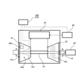
- 1 is a schematic diagram showing the configuration of a gas turbine engine and a control device according to a first embodiment.
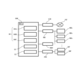
- FIG. 1 is a functional block diagram showing a configuration of a control device and its peripherals according to a first embodiment.
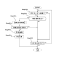
- FIG. 4 is a flowchart showing a rotation direction determining method for the gas turbine engine according to the first embodiment.
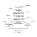
- 6 is a flowchart showing a rotation direction determination process of the rotation direction determination method for the gas turbine engine shown in FIG. 5 .
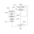
- 6 is a flowchart showing a rotation direction determining method for a gas turbine engine according to a second embodiment.
- 8 is a flowchart showing an equipment fault determination process in the method for determining the rotation direction of the gas turbine engine shown in FIG. 7 .
- FIGS. 1 and 2 are schematic diagrams showing a configuration example and functional blocks of a gas turbine engine vehicle GTV including a gas turbine 30 according to this embodiment and a control device 100 for the gas turbine 30.
- the gas turbine 30 and the control device 100 for the gas turbine 30 according to this embodiment can be applied to various known mobile bodies such as vehicles, aircraft, and ships. The following description will continue using a vehicle (gas turbine engine vehicle) as an example of the above-mentioned mobile body.
- the gas turbine engine vehicle GTV is configured as a four-wheel drive vehicle in which driving torque output from a driving force source 21 that generates driving torque for the vehicle is transmitted to a left front wheel 3LF, a right front wheel 3RF, a left rear wheel 3LR, and a right rear wheel 3RR (hereinafter collectively referred to as "wheels 3" unless a distinction is required).
- a known electric motor disposed on the front wheel side can be used as the driving force source 21.
- the driving force source 21 outputs a driving torque that is transmitted to the front wheel drive shaft 2F and the rear wheel drive shaft 2R via a transmission, a front wheel differential mechanism 5F, and a rear wheel differential mechanism 5R (not shown).
- the electric motors serving as the driving force source 21 in this embodiment may be arranged one on each of the front and rear wheels, or one electric motor may be arranged on each wheel 3.
- the gas turbine engine vehicle GTV in this embodiment is configured as a four-wheel drive vehicle, but it may also be a two-wheel drive vehicle in which the electric motor drives either the front or rear wheels.
- the driving force source 21 may further include a known internal combustion engine such as a gasoline engine or a diesel engine.
- the power supply system that supplies the desired power to such a driving force source 21 includes, for example, a gas turbine 30 described below, a known fuel supply mechanism 40 that supplies fuel to the gas turbine 30, a known generator 45 that receives driving force from the gas turbine 30 and generates power, a known secondary battery 50 such as a lithium ion secondary battery or a lead storage battery that can store the power generated by the generator 45, a known converter 22, and a control device 100 that controls these.
- the gas turbine 30 is connected to a load including the driving force source 21 (electric motor) via the generator 45 and converter 22 described above.
- the fuel supply mechanism 40 may also be configured to include a known fuel supply valve 41 that can adjust the amount of fuel supplied to the gas turbine 30 under the control of the control device 100.
- the converter 22 includes a known AC/DC converter that converts direct current to alternating current, and a known DC/DC converter that adjusts the voltage of the direct current to a desired voltage. Therefore, the power generated by the gas turbine 30 and the generator 45 can be converted via the converter 22 and then stored, for example, in the secondary battery 50 or supplied to the driving force source 21.
- the gas turbine engine vehicle GTV of this embodiment also includes the above-mentioned driving force source 21, electric steering device 8, and brake devices 4LF, 4RF, 4LR, and 4RR (hereinafter collectively referred to as "brake device 4" unless a distinction is required) as equipment used for driving control.
- the front wheel drive shaft 2F is provided with an electric steering device 8.
- the electric steering device 8 includes an electric motor and a gear mechanism (not shown), and is controlled by the vehicle drive control device 20 to adjust the steering angle of the left front wheel 3LF and the right front wheel 3RF.
- the vehicle drive control device 20 includes one or more known electronic control devices (ECU: Electronic Control Unit) that control the drive of the drive force source 21 that outputs the drive torque of the gas turbine engine vehicle GTV, the steering wheel 9, the electric steering device 8 that controls the steering angle of the steering wheels, and the brake device 4 that controls the braking force of the gas turbine engine vehicle GTV.
- the vehicle drive control device 20 may also have a function of controlling the drive of a transmission that changes the speed of the output output from the drive force source 21 and transmits it to the wheels 3.
- the control device 100 is configured to include one or more processors (CPUs (Central Processing Units)) and one or more memories communicatively connected to the one or more processors.
- the control device 100 is configured to have the function of controlling a gas turbine 30 including an impeller 31c provided at an intake port 31a (described later) and a turbine 32 arranged downstream of the impeller 31c.
- the control device 100 also functions as a determination device 10 that determines the rotation direction of the gas turbine 30 (described later).
- the control device 100 may be configured to be connectable to a known external network NT such as the Internet via a known communication device CD that can be mounted on a vehicle.
- Such a control device 100 is electrically connected to the above-mentioned communication device CD, sensors SR including an air flow sensor SR1 described later, a known storage device MD such as a hard disk, a presentation device PD including a known in-vehicle speaker SP and a display DP, etc., directly or via communication means such as a CAN (Controller Area Network) or LIN (Local Inter Net).
- sensors SR applicable to this embodiment include a known outside air temperature sensor SR2 capable of detecting the outside air temperature around the gas turbine engine vehicle GTV, a known air pressure sensor SR3 capable of detecting the air pressure around the gas turbine engine vehicle GTV, and various other known in-vehicle sensors such as an angular velocity sensor.
- the gas turbine 30 includes a compressor 31 having an impeller 31c at an intake port 31a, a turbine 32 arranged downstream of a combustor 35, a drive shaft 33 connecting the compressor 31 and the turbine 32, an output shaft 34 arranged coaxially with the turbine 32, and a combustor 35 arranged downstream of the compressor 31.
- the compressor 31 is configured to have the function of taking in outside air (air) through an air intake port 31a for taking in air, and compressing the taken-in air through an impeller 31c.
- a known air flow sensor SR1 capable of measuring the flow rate of air taken in through the air intake port 31a is provided in an air flow section 31b at the front stage of the impeller 31c continuing from the air intake port 31a . Therefore, the control device 100 is capable of detecting the flow rate of air flowing into the compressor 31 through the air flow sensor SR1 described above.
- the turbine 32 includes a rotor 32a connected to a drive shaft 33 connected to the impeller 31c.
- the rotor 32a can be started by a known starter motor such as a three-phase AC motor (not shown). Since the rotor 32a is connected to the impeller 31c via the drive shaft 33, the impeller 31c can rotate in synchronization with the drive of the rotor 32a.
- a known starter motor such as a three-phase AC motor (not shown). Since the rotor 32a is connected to the impeller 31c via the drive shaft 33, the impeller 31c can rotate in synchronization with the drive of the rotor 32a.
- the gas turbine 30 of this embodiment configured as described above, when the drive shaft 33 equipped with the rotor 32a and the impeller 31c is started (rotated) by the starter motor under the control of the control device 100, the air taken in by the compressor 31 is compressed by the rotation of the impeller 31c and supplied to a known combustor 35.
- control device 100 supplies fuel from the fuel supply mechanism 40 via the fuel supply valve 41 to the combustor 35 and combusts the fuel, supplying the combusted high-speed gas to the turbine 32.
- This high-speed gas rotates the rotor 32a inside the turbine 32, transmitting driving force (rotation) to the generator 45 via the output shaft 34, which causes the generator 45 to generate the desired electricity.
- the determination device 10 for determining whether or not reverse rotation has occurred at the start of the gas turbine engine in this embodiment will be described with reference to FIG. That is, it has been found that, for example, due to incorrect wiring of a three-phase AC motor or incorrect wiring of an inverter during the assembly process of a gas turbine engine, the above-mentioned reverse rotation may occur instead of normal rotation when the gas turbine engine is started. If such reverse rotation occurs, and appropriate countermeasures are not taken in time, damage to the gas turbine engine may occur.
- the determination device 10 of this embodiment drives the impeller 31c (or the rotor 32a) via the starter motor described above, and detects whether the air flow rate detected by the air flow sensor SR1 at the time of starting the impeller 31c is within the range of the determination reference value based on the detection value of the air flow sensor SR1 .
- the control device 100 judges whether reverse rotation of the rotating member occurs when the gas turbine engine is started based on whether this air flow rate is within the range of the judgment reference value.
- the "rotating member" in this embodiment can be exemplified by at least one of the impeller 31c of the compressor 31 and the rotor 32a of the turbine 32.
- the determination device 10 of this embodiment includes an air flow rate measurement unit 10A, an environmental factor measurement unit 10B, and a rotation direction determination unit 10C. As described above, the determination device 10 is configured as one function executed by the control device 100 of this embodiment. As shown in FIG. 4, the control device 100 may include a drive control unit 11 and a presentation control unit 12.
- the air flow rate measuring unit 10A is configured to have a function of measuring the flow rate of air taken in through the intake port 31a of the compressor 31 and flowing through the air flow section 31b. More specifically, the air flow rate measuring unit 10A can measure the flow rate of air flowing through the air flow section 31b via the air flow sensor SR1 .
- the environmental factor measuring unit 10B is configured to have a function of measuring environmental factors such as temperature and air pressure around the gas turbine 30.
- the "environmental factor” in this embodiment refers to parameters around the gas turbine that can affect the output of the gas turbine engine, such as the above-mentioned temperature and air pressure.
- the environmental factor measurement unit 10B can measure the outside air temperature around the vehicle via the above-mentioned outside air temperature sensor SR 2.
- the environmental factor measurement unit 10B can measure the air pressure around the vehicle via the above-mentioned air pressure sensor SR 3.
- the above description has been given taking the outside air temperature and air pressure as examples of environmental factors, other well-known parameters, such as the humidity around the vehicle, may be added as examples of environmental factors.
- the rotation direction determination unit 10C is configured to have a function of detecting reverse rotation of the rotating members (at least one of the impeller 31c and the rotor 32a) at the start of the gas turbine engine based on the detection value of the above - mentioned air flow sensor SR 1. More specifically, the rotation direction determination unit 10C can determine whether reverse rotation of the above-mentioned rotating members occurs by detecting whether the air flow rate detected by the air flow sensor SR 1 at the start of the impeller 31c is within a range of a determination reference value.
- the above-mentioned range of the judgment criteria can be calculated in advance by experiments or simulations based on the scale and rated output of the gas turbine 30.
- the range of the judgment criteria in this embodiment can be 10.0 g/s to 15.0 g/s.
- the rotation direction determination unit 10C may vary the above-mentioned reference value for the air flow rate based on environmental factors (such as temperature and air pressure) at the start of the gas turbine engine. More specifically, the control device 100 may refer to reference information for the reference value that is predefined for each outside temperature and air pressure. Such reference information for the reference value may be stored in advance in the above-mentioned storage device MD or an external server (not shown), for example, as table information in which optimal values in the range of the above-mentioned reference value are defined for each outside temperature and air pressure. For example, the reference information may be set so that the flow rate of the determination reference value decreases as the outside temperature increases. Conversely, the reference information may be set so that the flow rate of the determination reference value increases as the outside temperature decreases.
- the reference information may be set so that the flow rate of the judgment reference value decreases as the air pressure decreases, or conversely, the reference information may be set so that the flow rate of the judgment reference value increases as the air pressure increases.
- Such table information can be calculated in advance by measuring optimal values for each of the outside air temperature and atmospheric pressure divided into predetermined ranges through experiments or simulations.
- the drive control unit 11 is configured to have the function of controlling the drive of the gas turbine engine vehicle GTV based on the determination result of the rotation direction determination unit 10C described above. More specifically, when the rotation direction determination unit 10C determines that the rotating member is rotating in the reverse direction, the drive control unit 11 may, for example, perform control to stop the drive of the gas turbine 30.
- the presentation control unit 12 executes a process of presenting various information, such as the operating state of the gas turbine engine including the gas turbine 30 described above and the above-mentioned determination results, via a presentation device PD including a publicly known in-vehicle speaker SP and display DP.
- the presentation control unit 12 may present the above-mentioned various information to the occupant via the presentation device PD mounted in the vehicle, or may access and present the information on an external terminal such as a smartphone carried by the occupant.
- a method for determining the direction of rotation at the start of a gas turbine which can be executed by a control device 100 including the determination device 10 in this embodiment, will be described with reference to Figures 5 and 6.
- the method for determining the direction of rotation may be used as an algorithm of a computer-readable program.
- a program having such an algorithm may be distributed, for example, via a known network so as to be downloadable to a gas turbine engine vehicle GTV, or may be distributed in the form of being stored on a recording medium.
- a user gets into a gas turbine engine vehicle GTV, starts up the system, and starts driving.
- step 10A the control device 100 detects whether or not the gas turbine engine including the gas turbine 30 described above has started. If the gas turbine engine has not yet started in step 10A, it is determined in step 100 described below whether or not the system has been turned off, and if the system has not been turned off, the process returns to step 10A and is repeated.
- step 10A If it is determined in step 10A that the gas turbine engine has started, then in the following step 20A, it is detected whether or not a determination condition for determining the rotation direction at the time of gas turbine start-up is satisfied.
- a determination condition may be set, for example, based on whether the gas turbine engine is ready to produce rated power. That is, an example of the determination condition is whether the rotation speed of the rotor 32a of the gas turbine 30 has fallen into a predetermined range (for example, within a range of 5,000 rpm to 10,000 rpm) due to the start-up by the starter motor described above.
- the range of the rotational speed is 5,000 to 10,000 rpm, but such a predetermined range may be set appropriately depending on the scale and rated output of the turbine. If the determination condition is not satisfied in step 20A due to some factor (No in step 20A), the process proceeds to step 100 and the same process as described above is executed. On the other hand, if the determination condition is satisfied in step 20A (Yes in step 20A), the process proceeds to step 30A and the process of determining the rotation direction at the start of the gas turbine engine is executed.
- the control device 100 checks the rotation speed of the rotor 32a started by the starter motor via a known rotation speed detection sensor (not shown).
- the above-mentioned memory device MD etc. stores in advance information on the range of air flow rates corresponding to the rotation speed of the rotor 32a.
- step 32 the air flow measurement unit 10A of the control device 100 measures the flow rate of air flowing through the air circulation unit 31b at the start of the impeller 31c via the above-mentioned air flow sensor SR 1.
- the environmental factor measurement unit 10B of the control device 100 may measure the outside air temperature around the vehicle via, for example, the above-mentioned outside air temperature sensor SR 2 .
- the rotation direction determination unit 10C of the control device 100 detects whether the air flow rate detected by the air flow sensor SR1 at the start of the impeller 31c is within the range of the judgment reference value based on the detection value (the flow rate of air flowing through the air flow unit 31b) of the air flow measurement unit 10A. More specifically, the rotation direction determination unit 10C of the control device 100 obtains the range information of the air flow rate based on the rotation speed of the rotor 32a obtained in step 31, and can determine whether the air flow rate is within the range of the judgment reference value (for example, the above-mentioned 10.0 g/s to 15.0 g/s) included in this range information.
- the judgment reference value for example, the above-mentioned 10.0 g/s to 15.0 g/s
- the rotation direction determination unit 10C of the control device 100 may adjust the judgment reference value (for example, change at least one of the upper limit and the lower limit) based on the value of this environmental factor.
- the rotation direction determination unit 10C determines in the following step 34A that the gas turbine engine is rotating in reverse, and completes step 30A.
- the rotation direction determination unit 10C determines in the following step 34B that the gas turbine engine is rotating in the forward direction (i.e., proper rotation), and completes step 30A.
- step 40A the control device 100 determines whether the rotation direction of the gas turbine engine is normal (forward rotation) or not, and if it is normal (i.e., forward rotation), proceeds to step 100. On the other hand, if it is determined in step 40A that the rotation direction is not normal, the presentation control unit 12 of the control device 100 can present to the user, via the presentation device PD, the operating status of the gas turbine engine including the gas turbine 30 and warning information such as the occurrence of reverse rotation.
- the drive control unit 11 of the control device 100 can perform control to emergency stop the drive of the gas turbine 30 in the following step 60A. This makes it possible to prevent damage to the gas turbine engine at an early stage.
- the rotation direction determination method of this embodiment is completed after step 60A. However, for example, after step 60A, the method may proceed to step 100 to determine whether the system is turned off.
- the method for determining the direction of rotation during gas turbine startup described above correlates the air flow rate during startup of the gas turbine engine with the direction of rotation of the engine, and can detect the occurrence of reverse rotation of rotating parts (impeller 31c and rotor 32a) during startup of the gas turbine engine, thereby reducing damage to the gas turbine engine due to, for example, the above-mentioned assembly errors.
- a gas turbine engine control device 100 according to a second embodiment will be described below with reference to Figures 7 and 8.
- the occurrence of reverse rotation of a rotating member at the start of the gas turbine engine was determined based on the detection value of the air flow sensor.
- the control device 100 of the second embodiment is characterized in that it further distinguishes between a failure of the air flow sensor and the reverse rotation of the rotating member, based on the determination process in the first embodiment.
- control device 100 determines the rotation direction at the start of the gas turbine engine by going through steps 10A to 30A already described in the first embodiment.
- step 40B the control device 100 checks whether the gas turbine engine is rotating in reverse or not. If the gas turbine engine is not rotating in reverse but in forward rotation (No in step 40B), the control device 100 proceeds to step 100 described above.
- step 40B determines that the gas turbine engine is rotating in reverse (Yes in step 40B)
- the control device 100 proceeds to step 50B and executes the equipment failure determination process described below.
- the control device 100 first detects the rotation speed of the rotor 32a via a known rotation speed detection sensor (not shown) in step 51.
- step 52 the control device 100 measures the flow rate (first time) of air flowing through the air flow section 31b at the start of the impeller 31c via the air flow sensor SR1 . Note that since the process in step 52 is the same as the process in step 32 described above, this step 52 may be omitted as appropriate.
- step 53 the control device 100 controls the starter motor to drive the rotor 32a in the reverse direction to the initial rotation direction.
- the control device 100 measures the flow rate of air flowing through the air circulation portion 31b (for the second time) via the air flow sensor SR1 .
- the control device 100 detects whether or not the air flow rate detected by the air flow sensor SR1 is within the range of the judgment reference value in the next step 55. More specifically, the control device 100 can obtain the above-mentioned range information of the air flow rate based on the rotation speed of the rotor 32a in the same manner as in step 31, and determine whether or not the air flow rate is within the range of the judgment reference value included in this range information.
- step 56B the failure judgment process of this embodiment is completed and the process proceeds to step 60B.
- step 56A determines that the equipment (the air flow sensor SR1 in this example) may be malfunctioning. After determining in step 56A that the equipment may be malfunctioning, the control device 100 completes the malfunction judgment process of this embodiment and proceeds to step 60B.
- control device 100 of this embodiment rotates the rotor 32a and impeller 31c in a forward direction (positive rotation) and then in a reverse direction (reverse rotation), and based on the measurement value of the air flow sensor SR1 detected during this period, it is possible to clearly distinguish between a failure of this equipment (air flow sensor SR1 ) and reverse rotation of the rotating member.
- the control device 100 can present to the user, via the presentation device PD described above, warning information such as whether reverse rotation has occurred in the gas turbine engine including the gas turbine 30, or whether there may be a fault in an equipment item (in this example, the air flow sensor).
- control device 100 can perform control to emergency stop the operation of the gas turbine 30, as in the first embodiment described above. This makes it possible to distinguish between equipment failure and incorrect assembly of rotating parts, while preventing damage to the gas turbine engine at an early stage.
- the air flow sensor SR1 is shown as an example of equipment mounted on a gas turbine engine, but the present disclosure is not limited to the above example.
- the above-described equipment failure determination process may be applied to a failure of another part, such as a pressure sensor capable of measuring the pressure inside a turbine, as an example of equipment.
- the computer program that realizes each function of the above-mentioned determination device is a computer program applied to a control device that controls a gas turbine engine having an impeller provided at an intake port and a turbine arranged downstream of the impeller, and can cause one or more processors to execute processes including driving the impeller (or rotor) via a starter motor, detecting whether or not the air flow rate detected by the air flow sensor at the time of starting the impeller is within a range of a determination reference value based on the detection value of an air flow sensor installed in an air flow section continuing from the intake port, and determining the occurrence of reverse rotation of a rotating member (at least one of the impeller and the rotor) at the time of starting the gas turbine engine based on whether or not the air flow rate is within the range of the determination reference value.
- the computer program realizing each function of the control device including the determination device can further execute, in addition to the above-mentioned algorithms, ( ⁇ ) varying the above-mentioned air flow rate determination reference value based on environmental factors (such as temperature and air pressure) at the start of the gas turbine engine, and ( ⁇ ) rotating the impeller in a forward direction (forward rotation) and then in a reverse direction (reverse rotation), and distinguishing between a failure of the air flow sensor and the reverse rotation of the above-mentioned rotating member based on the measurement value of the air flow sensor detected during this period.
- environmental factors such as temperature and air pressure
- Such a computer program may be stored, for example, on a publicly known recording medium as described above, or may be downloaded from a publicly known server, such as the cloud, to the gas turbine engine vehicle GTV via a communication device CD.
Landscapes
- Engineering & Computer Science (AREA)
- Mechanical Engineering (AREA)
- General Engineering & Computer Science (AREA)
- Chemical & Material Sciences (AREA)
- Combustion & Propulsion (AREA)
- Combined Controls Of Internal Combustion Engines (AREA)
Abstract
Description
すなわち、ガスタービンエンジンが組み付けミスなど何らかの要因で通常の回転方向とは逆に回転(以下、「逆回転」とも称する)した場合、吸気口に流入すべき空気が乱れて通常の燃焼が起こらない。このような場合において、そのまま燃焼動作が継続された場合には、ガスタービンエンジンの内部で異常が発生し、場合によってはガスタービンエンジンの破損に帰結してしまう。
<ガスタービンエンジン車GTV>
図1及び図2は、本実施形態に係るガスタービン30とその制御装置100を含むガスタービンエンジン車GTVの構成例と機能ブロックをそれぞれ示す模式図である。なお本実施形態のガスタービン30とその制御装置100は、例えば車両、航空機あるいは船舶など公知の種々の移動体に対して適用が可能である。以下、上記した移動体の一例として車両(ガスタービンエンジン車)を例にして説明を継続する。
駆動力源21は、本実施形態では前輪側に配置された公知の電動モータが例示できる。この駆動力源21は、図示しない変速機や前輪差動機構5F及び後輪差動機構5Rを介して前輪駆動軸2F及び後輪駆動軸2Rに伝達される駆動トルクを出力し得る。
この制御装置100は、車載可能な公知の通信装置CDを介してインターネットなどの公知の外部ネットワークNTと接続可能に構成されていてもよい。
次に図3を参照しつつ、ガスタービン30と燃料供給機構40を含む本実施形態のガスタービンエンジンについて説明する。
同図に示すように、ガスタービン30は、吸気口31aにインペラ31cを備えた圧縮機31、燃焼器35の後段に配置されたタービン32、圧縮機31とタービン32とを連結する駆動軸33、タービン32と同軸に配置された出力軸34、および、圧縮機31の後段に配置された燃焼器35などを含んで構成されている。
以上のとおり構成された本実施形態のガスタービン30では、制御装置100による制御の下でスタータモータによってロータ32a及びインペラ31cを備えた駆動軸33が始動(回転)すると、このインペラ31cの回転によって圧縮機31で取り込まれた空気が圧縮されて公知の燃焼器35へ供給される。
次に図4を用いて、本実施形態におけるガスタービンエンジンの始動時における逆回転の発生有無を判定する判定装置10について説明する。
すなわち、例えばガスタービンエンジンの組み立て工程における三相交流モータの配線ミスやインバータの配線ミスなどによって、ガスタービンエンジンの始動時に正規の回転でなく上記した逆回転が発生し得ることが判明した。かような逆回転が発生した場合には、適切な対処が遅れた場合にはガスタービンエンジンの損傷などが発生し得る。
これに対して本実施形態の判定装置10は、上述したスタータモータを介してインペラ31c(又はロータ32a)を駆動し、空気流量センサSR1の検出値に基づいてインペラ31cの始動時に空気流量センサSR1で検出された空気流量が判定基準値の範囲にあるか否かを検出する。
より具体的に環境因子計測部10Bは、上記した外気温センサSR2を介して車両周囲の外気温を計測することができる。また、環境因子計測部10Bは、上記した気圧センサSR3を介して車両周囲の気圧を計測することができる。なお上記では環境因子の一例として外気温と気圧を例にして説明したが、環境因子の例として例えば車両周囲の湿度など他の公知のパラメータを追加してもよい。
一例として、上記した参照情報は、外気温が高くなるほど判定基準値の流量が下がるように設定されていてもよい。逆に言えば上記した参照情報は、外気温が低くなるほどに判定基準値の流量が上がるように設定することができる。
また、他の一例として、上記した参照情報は、気圧が低くなるほど判定基準値の流量が下がるように設定されていてもよい。逆に言えば上記した参照情報は、気圧が高くなるほどに判定基準値の流量が上がるように設定することができる。
かようなテーブル情報は、所定の範囲で区分けされた外気温や気圧ごとに実験又はシミュレーションを行って最適値をそれぞれ測定することで、予め算出できる。
次に図5及び図6も参照しつつ、本実施形態における判定装置10を含む制御装置100によって実行可能な、ガスタービン始動時における回転方向判定方法について説明する。なお、当該回転方向判定方法は、コンピュータが読み取り可能なプログラムのアルゴリズムとして用いられてもよい。かようなアルゴリズムを有するプログラムは、例えば公知のネットワークを介してガスタービンエンジン車GTVにダウンロード可能に流通したり、記録媒体に格納された形で流通し得る。
以下では、例えばユーザがガスタービンエンジン車GTVに搭乗してシステムを起動して走行を開始したときを例にして説明する。
ステップ20Aにおいて何らかの要因で判定条件が成立しない場合(ステップ20AでNo)には、ステップ100に移行して上記と同様の処理が実行される。一方でステップ20Aにおいて上記した判定条件が成立した場合(ステップ20AでYes)には、次いでステップ30Aへ移行してガスタービンエンジンの始動時における回転方向の判定処理が実行される。
一方でステップ40Aにおいて上記回転方向が正常でないと判定された場合、制御装置100の提示制御部12は、上記した提示装置PDを介して、ガスタービン30を含むガスタービンエンジンの駆動状態や、逆回転が発生しているなどの警告情報をユーザに対して提示することができる。
なお、図示されるとおり、ステップ60Aの後で本実施形態の回転方向判定方法が完了するが、例えばステップ60Aの後はステップ100に移行してシステムがOFFとなったか否かを判定してもよい。
以下、図7及び図8を用いて第2実施形態に係るガスタービンエンジンの制御装置100について説明する。上述した第1実施形態においては、空気流量センサの検出値に基づいてガスタービンエンジンの始動時における回転部材の逆回転の発生を判定していた。これに対して第2実施形態の制御装置100では、第1実施形態における判定処理をベースとして、前記した空気流量センサの故障と前記した回転部材の逆回転とをさらに峻別する点に主とした特徴がある。
次いでステップ40Bにおいて、制御装置100は、ガスタービンエンジンが逆回転しているか否かを確認する。そしてガスタービンエンジンが逆回転しておらず順回転である場合(ステップ40BでNo)には、既述したステップ100へ移行する。
すなわち、図8に示すように、制御装置100は、まずステップ51において公知の回転数検出センサ(不図示)を介してロータ32aの回転数を検出する。次いでステップ52において、制御装置100は、上記した空気流量センサSR1を介して、インペラ31cの始動時において空気流通部31bを流れる空気の流量(1回目)を計測する。なお、ステップ52における処理は上述したステップ32における処理と同様であることから、このステップ52は適宜省略してもよい。
従って、制御装置100は、ステップ5において検出された空気流量が上記した判定基準値の範囲にあれば、ステップ56Bに移行してガスタービンエンジンが逆回転していると判定できる。そしてステップ56Bにおいてガスタービンエンジンが逆回転していることを判定した後は、本実施形態の故障判定処理を完了してステップ60Bに移行する。
なお上記した判定装置の各機能を実現するコンピュータプログラムは、吸気口に設けられるインペラと前記インペラの後段に配置されたタービンを備えたガスタービンエンジンを制御する制御装置に適用されるコンピュータプログラムであって、一つ又は複数のプロセッサに、スタータモータを介してインペラ(又はロータ)を駆動させること、吸気口から続く空気流通部に設置された空気流量センサの検出値に基づいてインペラの始動時に空気流量センサで検出された空気流量が判定基準値の範囲にあるか否かを検出すること、及び、前記空気流量が判定基準値の範囲にあるか否かに基づいてガスタービンエンジンの始動時における回転部材(インペラ及びロータの少なくとも一方)の逆回転の発生を判定すること、を含む処理を実行させ得る。
20 車両駆動制御装置
30 ガスタービン
40 燃料供給機構
45 発電機
100 制御装置
GTV ガスタービン車
Claims (4)
- 吸気口に設けられるインペラと前記インペラの後段に配置されたタービンを備えたガスタービンエンジンを制御する制御装置であって、
一つ又は複数のプロセッサと、前記一つ又は複数のプロセッサと通信可能に接続された一つ又は複数のメモリと、を備え、
前記プロセッサは、
前記インペラを駆動し、
前記吸気口から続く空気流通部に設置された空気流量センサの検出値に基づいて、前記インペラの始動時に前記空気流量センサで検出された空気流量が判定基準値の範囲にあるか否かを検出することで、前記ガスタービンエンジンの始動時における回転部材の逆回転の発生を判定する、
ガスタービンエンジンの制御装置。 - 前記プロセッサは、
前記始動時における環境因子に基づいて、前記空気流量の判定基準値を可変させる、
請求項1に記載のガスタービンエンジンの制御装置。 - 前記プロセッサは、
前記インペラを順方向に回転させた後で逆方向に回転させて、この間に検出される前記空気流量センサの測定値に基づいて、前記空気流量センサの故障と前記回転部材の逆回転とを峻別する、
請求項2に記載のガスタービンエンジンの制御装置。 - 吸気口にインペラを備えた圧縮機と、前記インペラの前段における空気流通部に設置された空気流量センサと、前記圧縮機の後段に配置された燃焼器と、前記燃焼器の後段に配置されたロータを備えたタービンと、前記タービンと同軸に配置された出力軸と、を備えたガスタービンエンジンと、
前記ガスタービンエンジンを制御する請求項1~3のいずれか一項に記載のガスタービンエンジンの制御装置と、
を備えたガスタービンエンジン車。
Priority Applications (2)
| Application Number | Priority Date | Filing Date | Title |
|---|---|---|---|
| PCT/JP2023/012780 WO2024201770A1 (ja) | 2023-03-29 | 2023-03-29 | ガスタービンエンジンの制御装置、および移動体 |
| JP2025509386A JPWO2024201770A1 (ja) | 2023-03-29 | 2023-03-29 |
Applications Claiming Priority (1)
| Application Number | Priority Date | Filing Date | Title |
|---|---|---|---|
| PCT/JP2023/012780 WO2024201770A1 (ja) | 2023-03-29 | 2023-03-29 | ガスタービンエンジンの制御装置、および移動体 |
Publications (1)
| Publication Number | Publication Date |
|---|---|
| WO2024201770A1 true WO2024201770A1 (ja) | 2024-10-03 |
Family
ID=92903607
Family Applications (1)
| Application Number | Title | Priority Date | Filing Date |
|---|---|---|---|
| PCT/JP2023/012780 Ceased WO2024201770A1 (ja) | 2023-03-29 | 2023-03-29 | ガスタービンエンジンの制御装置、および移動体 |
Country Status (2)
| Country | Link |
|---|---|
| JP (1) | JPWO2024201770A1 (ja) |
| WO (1) | WO2024201770A1 (ja) |
Citations (6)
| Publication number | Priority date | Publication date | Assignee | Title |
|---|---|---|---|---|
| JPS543603U (ja) * | 1977-06-11 | 1979-01-11 | ||
| JPS6180394U (ja) * | 1984-10-30 | 1986-05-28 | ||
| JPS62168708U (ja) * | 1986-04-16 | 1987-10-26 | ||
| JP2012013075A (ja) * | 2010-06-30 | 2012-01-19 | General Electric Co <Ge> | 急タービン減速のためのシステム及び方法 |
| US20150292359A1 (en) * | 2014-04-11 | 2015-10-15 | United Technologies Corporation | Lubricating a rotating component during forward and/or reverse rotation |
| US20150354407A1 (en) * | 2014-04-10 | 2015-12-10 | United Technologies Corporation | Lubricating fluid damped anti-rotational systems |
-
2023
- 2023-03-29 JP JP2025509386A patent/JPWO2024201770A1/ja active Pending
- 2023-03-29 WO PCT/JP2023/012780 patent/WO2024201770A1/ja not_active Ceased
Patent Citations (6)
| Publication number | Priority date | Publication date | Assignee | Title |
|---|---|---|---|---|
| JPS543603U (ja) * | 1977-06-11 | 1979-01-11 | ||
| JPS6180394U (ja) * | 1984-10-30 | 1986-05-28 | ||
| JPS62168708U (ja) * | 1986-04-16 | 1987-10-26 | ||
| JP2012013075A (ja) * | 2010-06-30 | 2012-01-19 | General Electric Co <Ge> | 急タービン減速のためのシステム及び方法 |
| US20150354407A1 (en) * | 2014-04-10 | 2015-12-10 | United Technologies Corporation | Lubricating fluid damped anti-rotational systems |
| US20150292359A1 (en) * | 2014-04-11 | 2015-10-15 | United Technologies Corporation | Lubricating a rotating component during forward and/or reverse rotation |
Also Published As
| Publication number | Publication date |
|---|---|
| JPWO2024201770A1 (ja) | 2024-10-03 |
Similar Documents
| Publication | Publication Date | Title |
|---|---|---|
| JP3167935B2 (ja) | ハイブリッド車両の制御装置 | |
| JP5949899B2 (ja) | ハイブリッド駆動電気自動車の駆動制御装置及び駆動制御方法 | |
| JP4511873B2 (ja) | ガスタービン・エンジンのセンサ故障検知装置 | |
| JP3805648B2 (ja) | エンジン用吸気量制御装置 | |
| CN101346252B (zh) | 动力输出设备及其控制单元和方法、以及包括其的车辆 | |
| JP4064650B2 (ja) | ターボコンパウンド内燃エンジン | |
| CN102514570B (zh) | 一种串联式混合动力车及其发动机启停控制方法、系统 | |
| JP2994590B2 (ja) | ハイブリッド車両の制御装置 | |
| CN104245453B (zh) | 车辆的控制装置 | |
| WO2015072269A1 (ja) | 原動機の駆動制御装置 | |
| JP6115560B2 (ja) | 負圧センサ異常検出装置及び内燃機関の制御装置 | |
| JP2012131435A (ja) | 車両用動力制御装置 | |
| US20130124025A1 (en) | Method of operating a hybrid powertrain | |
| JP2007120334A (ja) | 車両駆動システムの異常診断装置 | |
| JP5153801B2 (ja) | 電動過給機の制御装置 | |
| KR102233170B1 (ko) | 마일드 하이브리드 차량의 모터 진단 방법 | |
| JP5208257B2 (ja) | 電動過給機の異常検出装置と検出方法 | |
| JP7449889B2 (ja) | 過給機異常予兆判定装置及び過給機異常予兆判定方法 | |
| JP4495706B2 (ja) | ハイブリッド車両 | |
| JP7622612B2 (ja) | 監視装置 | |
| JP3721987B2 (ja) | 内燃機関の始動制御装置 | |
| CN116717346B (zh) | 一种发动机控制系统及保护策略 | |
| WO2024201630A1 (ja) | ガスタービンエンジンの制御装置、および移動体 | |
| CN103047040B (zh) | 发动机的存储控制装置及发动机的存储控制方法 | |
| US12077149B2 (en) | Control method for series hybrid vehicle and control device for series hybrid vehicle |
Legal Events
| Date | Code | Title | Description |
|---|---|---|---|
| 121 | Ep: the epo has been informed by wipo that ep was designated in this application |
Ref document number: 23930410 Country of ref document: EP Kind code of ref document: A1 |
|
| ENP | Entry into the national phase |
Ref document number: 2025509386 Country of ref document: JP Kind code of ref document: A |
|
| WWE | Wipo information: entry into national phase |
Ref document number: 2025509386 Country of ref document: JP |
|
| NENP | Non-entry into the national phase |
Ref country code: DE |
|
| 122 | Ep: pct application non-entry in european phase |
Ref document number: 23930410 Country of ref document: EP Kind code of ref document: A1 |