WO2024201630A1 - ガスタービンエンジンの制御装置、および移動体 - Google Patents
ガスタービンエンジンの制御装置、および移動体 Download PDFInfo
- Publication number
- WO2024201630A1 WO2024201630A1 PCT/JP2023/012088 JP2023012088W WO2024201630A1 WO 2024201630 A1 WO2024201630 A1 WO 2024201630A1 JP 2023012088 W JP2023012088 W JP 2023012088W WO 2024201630 A1 WO2024201630 A1 WO 2024201630A1
- Authority
- WO
- WIPO (PCT)
- Prior art keywords
- gas turbine
- supply mechanism
- turbine engine
- fuel supply
- control device
- Prior art date
- Legal status (The legal status is an assumption and is not a legal conclusion. Google has not performed a legal analysis and makes no representation as to the accuracy of the status listed.)
- Ceased
Links
Images




Classifications
-
- F—MECHANICAL ENGINEERING; LIGHTING; HEATING; WEAPONS; BLASTING
- F02—COMBUSTION ENGINES; HOT-GAS OR COMBUSTION-PRODUCT ENGINE PLANTS
- F02C—GAS-TURBINE PLANTS; AIR INTAKES FOR JET-PROPULSION PLANTS; CONTROLLING FUEL SUPPLY IN AIR-BREATHING JET-PROPULSION PLANTS
- F02C9/00—Controlling gas-turbine plants; Controlling fuel supply in air- breathing jet-propulsion plants
- F02C9/26—Control of fuel supply
- F02C9/28—Regulating systems responsive to plant or ambient parameters, e.g. temperature, pressure, rotor speed
Definitions
- This disclosure relates to a control device for a gas turbine engine and a vehicle such as a gas turbine engine vehicle that is equipped with this gas turbine engine and control device.
- Patent Document 1 a vehicle is known that uses a gas turbine to drive a generator, and the electricity obtained by this generator is supplied to the drive system, such as the vehicle drive motor.
- Patent Document 2 discloses that when an electrical load is applied, feedback control of the fuel flow rate is performed so that the gas turbine rotation speed increases according to the magnitude of the load. More specifically, Patent Document 2 proposes looking up a map from the electrical load to determine the target rotation speed, and PID controlling the fuel flow rate so that the actual gas turbine rotation speed matches this target rotation speed.
- JP 2015-218711 A Japanese Patent Application Publication No. 06-178599 Japanese Patent Application Publication No. 05-106469 JP 2018-138784 A
- a gas turbine engine is mounted on a vehicle
- the gas turbine engine may be installed in an engine room near peripheral devices such as a radiator fan, a cooling pump, etc.
- peripheral devices such as a radiator fan, a cooling pump, etc.
- a fuel supply mechanism associated with the gas turbine engine is driven by power supplied from an auxiliary battery mounted on the vehicle.
- the voltage of the auxiliary battery will fluctuate due to changes in current when the peripheral devices described above are operated.
- the inrush current immediately after the peripheral devices are started up has a large current value, and there is concern that the amount of fuel injected by the fuel supply mechanism will vary when such an inrush current occurs.
- the fuel injection amount of the fuel supply mechanism can be corrected by referring to a voltage map.
- the fuel injection amount will deviate from the expected amount in response to sudden changes such as the above-mentioned inrush current, resulting in large variations in the fuel injection amount.
- the present disclosure has been made in consideration of the above-mentioned problems as an example, and aims to provide a gas turbine engine control device and a mobile body equipped with this control device that can suppress variation in the fuel injection amount in the fuel supply mechanism even when a sudden change in the drive voltage occurs in the fuel supply mechanism due to, for example, an inrush current generated in a peripheral device.
- a control device for controlling a gas turbine engine having a fuel supply mechanism that injects fuel into compressed air comprising one or more processors and one or more memories communicably connected to the one or more processors, the processor temporarily increasing the gain of the PID control that controls the fuel supply mechanism relative to a basic constant when the drive voltage of the fuel supply mechanism fluctuates due to a sudden change in the input current input to the fuel supply mechanism.
- FIG. 1 is a schematic diagram showing an example of the configuration of a vehicle equipped with a gas turbine engine according to an embodiment
- FIG. 2 is a schematic diagram illustrating the configurations and functions of a vehicle according to an embodiment.
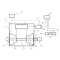
- 1 is a schematic diagram showing the configuration of a gas turbine engine and a control device according to an embodiment of the present invention
- FIG. 2 is a functional block diagram showing a configuration of a control device and its peripherals according to the embodiment.
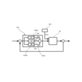
- FIG. 2 is a control block diagram that can be executed by a PID control unit of the control device according to the embodiment.
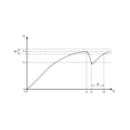
- 5 is a schematic diagram showing an example of a change over time in a drive voltage in a fuel supply mechanism
- FIG. 1 is a flowchart illustrating a method for controlling a gas turbine engine.
- ⁇ Gas turbine engine vehicle GTV> 1 and 2 are schematic diagrams showing a configuration example and functional blocks of a gas turbine engine vehicle GTV including a gas turbine 30 according to this embodiment and a control device 100 for the gas turbine 30.
- the gas turbine 30 and the control device 100 for the gas turbine 30 according to this embodiment can be applied to various known mobile bodies such as vehicles, aircraft, and ships. The following description will continue using a vehicle (gas turbine engine vehicle) as an example of the above-mentioned mobile body.
- the gas turbine engine vehicle GTV is configured as a four-wheel drive vehicle in which driving torque output from a driving force source 21 that generates driving torque for the vehicle is transmitted to a left front wheel 3LF, a right front wheel 3RF, a left rear wheel 3LR, and a right rear wheel 3RR (hereinafter collectively referred to as "wheels 3" unless a distinction is required).
- the driving force source 21 may be, for example, a known electric motor for driving a vehicle, which is disposed on the front wheel side.
- the driving force source 21 outputs a driving torque that is transmitted to the front drive shaft 2F and the rear drive shaft 2R via a transmission, a front wheel differential mechanism 5F, and a rear wheel differential mechanism 5R (not shown).
- the electric motors serving as the driving force source 21 in this embodiment may be arranged one on each of the front and rear wheels, or one electric motor may be arranged on each wheel 3.
- the gas turbine engine vehicle GTV in this embodiment is configured as a four-wheel drive vehicle, but it may also be a two-wheel drive vehicle in which the electric motor drives either the front or rear wheels.
- the driving force source 21 may further include a known internal combustion engine such as a gasoline engine or a diesel engine.
- the power supply system that supplies the desired power to such a driving force source 21 includes, for example, a gas turbine 30 described below, a fuel supply mechanism 40 having a known fuel injection nozzle capable of supplying fuel to the gas turbine 30, a generator 45 such as a known power generating motor that receives driving force from the gas turbine 30 and generates power, a known secondary battery BT2 such as a lithium ion secondary battery or lead storage battery that can store the power generated by the generator 45, a known converter 22, and a control device 100 that controls these.
- a gas turbine 30 described below
- a generator 45 such as a known power generating motor that receives driving force from the gas turbine 30 and generates power
- a known secondary battery BT2 such as a lithium ion secondary battery or lead storage battery that can store the power generated by the generator 45
- a known converter 22 such as a lithium ion secondary battery or lead storage battery that can store the power generated
- the gas turbine 30, the fuel supply mechanism 40, and the generator 45 are arranged in a known engine room together with the peripheral device 10.
- the engine room that houses the gas turbine engine is provided on the front side of the vehicle, but the engine room may be provided on the rear side. 1 and 2, the fuel supply mechanism 40 and the peripheral device 10 are electrically connected to a known auxiliary battery BT1 installed in, for example, an engine room. This allows the fuel supply mechanism 40 and the peripheral device 10 to receive the power required for operation from the auxiliary battery BT1.
- the fuel supply mechanism 40 of this embodiment is also connected to a fuel tank FL via a known supply pipe.
- the peripheral device 10 is a known vehicle-mounted device that is installed in the engine compartment and receives power from the auxiliary battery BT1.
- Examples of the peripheral device 10 include a radiator fan 10A, a water pump 10B for circulating coolant, and a power steering motor 10C for the electric steering device 8 described below.
- the gas turbine 30 is connected to a load including the driving force source 21 (electric motor) via the generator 45 and the converter 22 described above. Therefore, the control device 100 can execute fuel injection control via the fuel supply mechanism 40 equipped with a known fuel injection nozzle in order to achieve a desired target rotation speed of the gas turbine 30.
- the control device 100 may hold a correction map, for example, as shown in Patent Document 2, and correct the drive voltage of the fuel supply mechanism 40 based on this correction map so as to achieve the target rotation speed.
- the converter 22 includes a known AC/DC converter that converts direct current to alternating current, and a known DC/DC converter that adjusts the voltage of the direct current to a desired voltage. Therefore, the power generated by the gas turbine 30 and the generator 45 can be converted via the converter 22 and then stored, for example, in the secondary battery 50 or supplied to the driving force source 21.
- the gas turbine engine vehicle GTV of this embodiment is equipped with the above-mentioned driving force source 21, electric steering device 8, and brake devices 4LF, 4RF, 4LR, 4RR (hereinafter collectively referred to as "brake device 4" unless a distinction is required) as equipment used for driving control.
- the front-wheel drive shaft 2F is provided with an electric steering device 8.
- the electric steering device 8 includes an electric motor and a gear mechanism (not shown), and is controlled by a vehicle drive control device 20 to adjust the steering angles of the left front wheel 3LF and the right front wheel 3RF.
- the vehicle drive control device 20 includes one or more known electronic control devices (ECU: Electronic Control Unit) that control the drive of a drive force source 21 that outputs drive torque for the gas turbine engine vehicle GTV, a steering wheel 9, an electric steering device 8 that controls the steering angle of the steering wheels, and a brake device 4 that controls the braking force of the gas turbine engine vehicle GTV.
- the vehicle drive control device 20 may also have a function of controlling the drive of a transmission that changes the speed of the output output from the drive force source 21 and transmits it to the wheels 3.
- the vehicle drive control device 20 of this embodiment may be configured as an electronic control device integrated with the control device 100 described later.
- the control device 100 is configured to include one or more processors (CPUs (Central Processing Units)) and one or more memories communicatively connected to the one or more processors.
- the control device 100 may be configured to be connectable to a known external network NT, such as the Internet, via a known communication device CD that can be mounted on a vehicle.
- a known external network NT such as the Internet
- the control device 100 of this embodiment is configured to have a function of controlling a gas turbine 30 including an impeller 31b provided at an intake port 31a and a turbine 32 disposed downstream of the impeller 31b.
- the control device 100 of this embodiment is also configured to have a function of PID control of the fuel injection amount in the fuel supply mechanism 40 described above.
- Such a control device 100 is electrically connected, either directly or via communication means such as CAN (Controller Area Network) or LIN (Local Inter Net), to the above-mentioned communication device CD, sensors SR, known memory devices MD such as a hard disk, and presentation devices PD including known in-vehicle speakers SP and displays DP.
- the sensors SR of this embodiment include a rotation speed sensor SR1 , a current sensor SR2 , and a voltage sensor SR3 .
- An example of the rotation speed sensor SR1 is a known rotation speed sensor having a function of detecting the rotation speed of a gas turbine engine.
- An example of the current sensor SR2 is a known current sensor having a function of measuring the value of an input current input to the above-mentioned fuel supply mechanism 40.
- An example of the voltage sensor SR3 is a known current sensor having a function of measuring the value of a drive voltage in the above-mentioned fuel supply mechanism 40.
- the sensors SR may further include various known in-vehicle sensors such as an acceleration sensor and an angular velocity sensor.
- the gas turbine 30 includes a compressor 31 having an intake port 31a, a turbine 32 arranged downstream of a combustor 35, a drive shaft 33 connecting the compressor 31 and the turbine 32, an output shaft 34 arranged coaxially with the turbine 32, and a combustor 35 arranged downstream of the compressor 31.
- the compressor 31 is configured to have the function of taking in outside air (air) from an air intake port 31a through which air can be taken in, and compressing the taken-in air via an impeller 31b.
- the turbine 32 includes a rotor 32a connected to a drive shaft 33 connected to the impeller 31b.
- the rotor 32a can be started by a known starter motor such as a three-phase AC motor (not shown). Since the rotor 32a is connected to the impeller 31b via the drive shaft 33, the impeller 31b can rotate in synchronization with the drive of the rotor 32a.
- the gas turbine 30 of this embodiment is provided with the above-mentioned rotation speed sensor SR1 capable of detecting the rotation speed of the rotor 32a.
- the fuel supply mechanism 40 is configured to have a function of injecting fuel supplied from a fuel tank FL into the compressed air through a fuel injection nozzle installed in the combustor 35 under the control of the control device 100.
- the fuel supply mechanism 40 of the present embodiment can be driven by known PWM (Pulse Width Modulation) control via the control device 100.
- PWM Pulse Width Modulation
- the gas turbine 30 configured as described above, when the drive shaft 33 equipped with the rotor 32a and the impeller 31b is started (rotated) by the starter motor under the control of the control device 100, the air taken in by the compressor 31 is compressed by the rotation of the impeller 31b and supplied to the combustor 35.
- the control device 100 adjusts the amount of fuel injected via a fuel supply valve in the fuel supply mechanism 40, thereby combusting the fuel injected into the compressed air in the combustor 35.
- high-speed gas generated by the combustion is supplied to the turbine 32.
- This high-speed gas rotates the rotor 32a in the turbine 32, and a driving force (rotation) is transmitted to the generator 45 via the output shaft 34, thereby generating the desired amount of electricity.
- the control device 100 can adjust the amount of fuel injected via the fuel supply mechanism 40 based on the detection value of the rotation speed sensor SR1 so that the rotor 32a rotates at a desired speed.
- control device 100 capable of controlling the fuel injection amount of the gas turbine engine in this embodiment will be described with reference to FIGS. That is, as described above, a predetermined amount of fuel is injected into the combustor 35 of the gas turbine engine via the fuel supply mechanism 40 in accordance with the rotation speed of the rotor 32a in the turbine 32. As disclosed in the above-mentioned patent document, the control device 100 adjusts the amount of fuel injected into the combustor 35 by PID control of the drive voltage of the fuel supply mechanism 40, and controls the rotation speed of the rotor 32a in the gas turbine 30 to a desired value (target rotation speed).
- the fuel supply mechanism 40 receives the necessary power from the auxiliary battery BT1, but in the peripheral device 10 that also receives power from the auxiliary battery BT1, an inrush current may occur, for example, during startup.
- an inrush current occurs in the peripheral device 10 that receives power from the auxiliary battery BT1
- a sudden change occurs in the power (input current and voltage) supplied from the auxiliary battery BT1 to the fuel supply mechanism 40 due to the occurrence of this inrush current.
- a change in the input current or voltage from the auxiliary battery BT1 to the fuel supply mechanism 40 caused by an inrush current generated in another peripheral device 10 that shares a power source with the fuel supply mechanism 40 is defined as a "sudden change.”
- the control device 100 of this embodiment measures the input current input to the fuel supply mechanism 40, and when the drive voltage of the fuel supply mechanism 40 fluctuates due to a sudden change in this input current, executes control to temporarily increase the gain of the PID control that controls the fuel supply mechanism 40 relative to the basic constant.
- the control device 100 of this embodiment includes a rotation speed measurement unit 101, a power supply parameter measurement unit 102, a PID gain adjustment unit 103, a PID control unit 104, and a display control unit 105. Each of these units is configured as a function executed by the control device 100 of this embodiment.
- the rotation speed measurement unit 101 has a function of detecting the rotation speed of the rotor 32a in the turbine 32 via the above-mentioned rotation speed sensor SR1 .
- the rotation speed sensor SR1 may be configured to detect the rotation speed of the impeller 31b of the gas turbine engine.
- the power supply parameter measuring unit 102 is configured to have a function of measuring the value of the input current input from the auxiliary battery BT1 to the fuel supply mechanism 40 via the above-mentioned current sensor SR2 .
- the power supply parameter measuring unit 102 of this embodiment is configured to have a function of measuring the drive voltage of the fuel supply mechanism 40 via the voltage sensor SR3 .
- the PID gain adjustment unit 103 is configured to have the function of adjusting the gain in the above-mentioned PID control performed by the control device 100. As shown in FIG. 5, the PID gain adjustment unit 103 can adjust the value of the gain Kp in the P (proportional) control of the PID control. The PID gain adjustment unit 103 can also adjust the value of the gain Ki in the I (integral) control of the PID control. Furthermore, the PID gain adjustment unit 103 can adjust the value of the gain Kd in the D (differential) control of the PID control.
- the PID control unit 104 is configured to have a function of PID control of the duty value (duty instruction value) used in the PWM (Pulse Width Modulation) control for driving the fuel supply mechanism 40. More specifically, as shown in FIG. 5, the PID control unit 104 includes a P control unit 104pc capable of performing a known proportional control, an I control unit 104ic capable of performing a known integral control, and a D control unit 104dc capable of performing a known differential control. In addition, the set values of gains (Kp, Ki, and kd) in the PID control performed by the PID control unit 104 are calculated in advance by experiment or simulation as basic constants.
- the PID control unit 104 can perform control to inject a desired fuel injection amount from the fuel injection nozzle by PID controlling the above-mentioned duty instruction value of the fuel supply mechanism 40.
- the PID control unit 104 in this embodiment PID controls the on-time width (duty) in the above-mentioned PWM control as the instruction value of the controlled object, but the PID control may also be performed using the value of the drive voltage of the fuel supply mechanism 40 itself as the control instruction value.
- the presentation control unit 12 executes a process of presenting various information, such as the operating state of the gas turbine engine including the gas turbine 30, via a presentation device PD including a publicly known in-vehicle speaker SP and display DP.
- the presentation control unit 12 may present the various information to the occupant via the presentation device PD mounted in the vehicle, or may access and present the information on an external terminal such as a smartphone carried by the occupant.
- the gas turbine engine control method may be used as an algorithm of a computer-readable program.
- a program having such an algorithm may be distributed, for example, via a known network so as to be downloadable to a gas turbine engine vehicle GTV, or may be distributed in the form of being stored on a recording medium.
- step 1 the control device 100 detects whether or not a gas turbine engine including the gas turbine 30 has started in response to a power generation demand inside the gas turbine engine vehicle. If the gas turbine engine has not started in step 1, it is determined in step 7 (described later) whether or not the system has been turned off, and if the system has not been turned off, the process returns to step 1 and is repeated.
- the control device 100 detects whether or not the gas turbine engine is operating stably in the following step 2.
- a criterion for determining whether or not the gas turbine engine is operating stably for example, whether or not the rotation speed of the rotor 32a is within a predetermined range (e.g., tens of thousands of rpm or more) may be used. The rotation speed required for such stable operation can be determined in advance by experiment or simulation depending on the size and rated output of the gas turbine engine. As an example, in this embodiment, whether or not the rotation speed of the rotor 32a of the gas turbine 30 exceeds 10,000 rpm due to starting by the starter motor is used as the criterion for determination in step 2.
- step 2 If the judgment condition is not met for some reason in step 2 (No in step 2), the process moves to step 1 and the same process as above is executed. On the other hand, if the judgment condition is met in step 2 and the turbine engine is operating stably (Yes in step 2), the process moves to step 3 and it is determined whether the fluctuation in the drive voltage in the fuel supply mechanism 40 has reached a predetermined value or more.
- the fuel supply mechanism 40 is PID-controlled so as to be driven at a drive voltage V1 via the accessory battery BT1.
- a 12V accessory battery BT1 is used, so the control device 100 PID-controls the drive voltage of the fuel supply mechanism 40 so that the drive voltage becomes V1 (12V).
- V1 12V
- the control device 100 detects whether the fluctuation of the drive voltage in the fuel supply mechanism 40 is equal to or greater than a predetermined value, for example, via the voltage sensor SR3 described above.
- the control device 100 may set an appropriate range AR within, for example, 10% of the target value V1 (12V in this example) of the controlled object (the drive voltage). If the drive voltage of the fuel supply mechanism 40 falls outside the appropriate range AR, the control device 100 determines in step 3 that the fluctuation of the drive voltage is equal to or greater than a predetermined value.
- the appropriate range AR is set to a fluctuation range within 10% of the target value, but such an appropriate range AR may be calculated by experiment or simulation.
- step 4 the control device 100 executes the gain adjustment process of the PID control described above. More specifically, the PID gain adjustment unit 103 of the control device 100 executes a process to increase the value of the gain Kp used in the P control unit 104pc, while maintaining the values of the gains Ki and Kd in the I control unit 104ic and the D control unit 104dc.
- control device 100 executes control to temporarily increase the gain (Kp) in the proportional control of the PID control.
- the rate at which the gain Kp is increased by the PID gain adjustment unit 103 can be specified in advance by experiment or simulation.
- the PID gain adjustment unit 103 of this embodiment executes control to temporarily increase the value of Kp by 10% of the basic constant (initial setting value) in step 4.
- step 5 the control device 100 determines whether the drive voltage of the fuel supply mechanism 40 has returned to a predetermined level.
- the control device 100 may determine whether the drive voltage is within the above-mentioned appropriate range AR.
- the control device 100 may determine whether a predetermined time has elapsed since the gain adjustment in step 4 was performed. Note that the specific value of the above-mentioned "predetermined time" can be determined in advance by experiment or simulation.
- step 5 If the drive voltage is not within the appropriate range AR in step 5 or the specified time has not elapsed (No in step 5), the process returns to step 4 and the above-mentioned processing is repeated. On the other hand, if the drive voltage is within the appropriate range AR in step 5 or the specified time has elapsed (Yes in step 5), the control device 100 executes processing in the following step 6 to return the temporarily increased value of gain Kp to the basic constant.
- control device 100 can execute control to cancel this temporary increase in gain and return the gain value to the basic constant based on either the degree of recovery in the drive voltage described above or the time elapsed since the control to temporarily increase the gain Kp described above was started.
- the above-mentioned sudden change occurs at time t1, and at time t2 the drive voltage V of the fuel supply mechanism 40 falls out of the appropriate range AR, causing the drive voltage to fluctuate to a predetermined value or more, but during the period ⁇ from time t2 to time t3, the value of the gain Kp described above is temporarily increased from the basic constant. That is, during the period ⁇ , the control device 100 is able to execute PID control with the value of Kp temporarily increased. This makes it possible to stably drive the fuel supply mechanism 40 by temporarily increasing the gain Kp in the P control to quickly follow the above-mentioned sudden change.
- the gain in the PID control is temporarily increased, improving the response to this fluctuation and suppressing the variation in the fuel injection amount in the fuel supply mechanism 40, making it possible to quickly return the drive voltage to within the appropriate range AR.
- the control device 100 may vary the amount of increase in the gain Kp to be temporarily increased based on the degree of fluctuation in the drive voltage of the fuel supply mechanism 40 described above. More specifically, for example, the fluctuation range of the drive voltage of the fuel supply mechanism 40 due to the sudden change UEC described above may be divided into several stages, and the increase range of the gain Kp to be temporarily increased may be set to be larger as the fluctuation range becomes larger according to this stage. This makes it possible to further improve the ability to follow the fluctuation caused by this sudden change and quickly return the drive voltage of the fuel supply mechanism 40 to within the appropriate range AR.
- the computer program that realizes each function of the above-mentioned determination device is a computer program applied to a control device that controls a gas turbine engine equipped with a fuel supply mechanism that injects fuel into compressed air, and can cause one or more processors to execute processing including measuring an input current input to the fuel supply mechanism, and temporarily increasing the gain of the PID control that controls the fuel supply mechanism relative to a basic constant when the drive voltage of the fuel supply mechanism fluctuates due to a sudden change in this input current.
- the computer program for realizing each function of the control device can further execute, in the above-mentioned algorithm, ( ⁇ ) executing control to temporarily increase the gain Kp in the proportional control among the gains of the above-mentioned PID control, ( ⁇ ) canceling this temporary increase in gain and restoring the gain value to the basic constant based on either the degree of recovery in the above-mentioned drive voltage or the elapsed time since the start of the control to temporarily increase the gain Kp, and (c) varying the amount of increase in the temporarily increased gain Kp based on the degree of fluctuation in the above-mentioned drive voltage.
- Such a computer program may be stored, for example, on a publicly known recording medium as described above, or may be downloaded from a publicly known server, such as the cloud, to the gas turbine engine vehicle GTV via a communication device CD.
Landscapes
- Engineering & Computer Science (AREA)
- Chemical & Material Sciences (AREA)
- Combustion & Propulsion (AREA)
- Mechanical Engineering (AREA)
- General Engineering & Computer Science (AREA)
- Control Of Eletrric Generators (AREA)
Abstract
Description
すなわち、例えば車両にガスタービンエンジンが搭載されることを想定した場合、このガスタービンエンジンは、例えばエンジンルームにおいてラジエータファンや冷却ポンプなどの周辺装置の近傍に設置され得る。このとき上記周辺装置と同様に、ガスタービンエンジンに付随する燃料供給機構は、車載された補機用バッテリーから電力が供給されて駆動する。
図1及び図2は、本実施形態に係るガスタービン30とその制御装置100を含むガスタービンエンジン車GTVの構成例と機能ブロックをそれぞれ示す模式図である。なお本実施形態のガスタービン30とその制御装置100は、例えば車両、航空機あるいは船舶など公知の種々の移動体に対して適用が可能である。以下、上記した移動体の一例として車両(ガスタービンエンジン車)を例にして説明を継続する。
駆動力源21は、本実施形態では前輪側に配置された公知の車両駆動用の電動モータが例示できる。この駆動力源21は、図示しない変速機や前輪差動機構5F及び後輪差動機構5Rを介して前輪駆動軸2F及び後輪駆動軸2Rに伝達される駆動トルクを出力し得る。
これらの燃料供給機構40及び周辺装置10は、図1及び図2などに示すように、例えばエンジンルーム内に設置された公知の補機用バッテリーBT1と電気的に接続される。これにより燃料供給機構40及び周辺装置10は、駆動に必要な電力を補機用バッテリーBT1から受けることが可能となっている。また、本実施形態の燃料供給機構40は、公知の供給配管を介して燃料タンクFLと接続されている。
従って制御装置100は、ガスタービン30を所望の目標回転数にするために公知の燃料噴射ノズルを備えた燃料供給機構40を介して燃料の噴射制御を実行し得る。なお制御装置100は、例えば特許文献2にも示される補正マップを保持し、この補正マップに基づいて目標回転数となるように燃料供給機構40の駆動電圧を補正してもよい。
前輪駆動軸2Fには電動ステアリング装置8が設けられている。電動ステアリング装置8は図示しない電動モータやギヤ機構を含み、車両駆動制御装置20により制御されることによって左前輪3LF及び右前輪3RFの操舵角を調節する。
なお本実施形態の車両駆動制御装置20は、後述する制御装置100と統合された電子制御装置として構成されていてもよい。
かような制御装置100には、直接的に又はCAN(Controller Area Network)やLIN(Local Inter Net)等の通信手段を介して、上記した通信装置CD、センサ類SR、ハードディスクなど公知の記憶装置MD、公知の車載スピーカSPやディスプレイDPを含む提示装置PDなどが電気的に接続されている。
なおセンサ類SRとしては、上記したセンサの他にも、例えば加速度センサや角速度センサなど公知の種々の車載センサがさらに例示できる。
次に図3を参照しつつ、ガスタービン30と燃料供給機構40を含む本実施形態のガスタービンエンジンについて説明する。
同図に示すように、ガスタービン30は、吸気口31aを備えた圧縮機31、燃焼器35の後段に配置されたタービン32、圧縮機31とタービン32とを連結する駆動軸33、タービン32と同軸に配置された出力軸34、および、圧縮機31の後段に配置された燃焼器35などを含んで構成されている。
タービン32は、上記したインペラ31bと連結された駆動軸33と接続されるロータ32aを備えて構成される。また、ロータ32aは、不図示の三相交流モータなどの公知のスタータモータによって始動することが可能となっている。このときロータ32aはインペラ31bと駆動軸33を介して連結されていることから、ロータ32aの駆動に応じてインペラ31bも同調して回転し得る。本実施形態のガスタービン30には、ロータ32aの回転数を検出可能な上記した回転数センサSR1が設けられている。
以上のとおり構成されたガスタービン30では、制御装置100による制御の下でスタータモータによってロータ32a及びインペラ31bを備えた駆動軸33が始動(回転)すると、このインペラ31bの回転によって圧縮機31で取り込まれた空気が圧縮されて燃焼器35へ供給される。
次に図4及び図5を用いて、本実施形態におけるガスタービンエンジンの燃料噴射量を制御可能な制御装置100について説明する。
すなわち、上述したとおり、ガスタービンエンジンの燃焼器35には、タービン32におけるロータ32aの回転数に応じて所定量の燃料が燃料供給機構40を介して噴射される。そして上記した特許文献にも開示されるように、制御装置100は、燃料供給機構40の駆動電圧をPID制御することで燃焼器35への燃料噴射量を調整し、ガスタービン30におけるロータ32aの回転数が所望の値(目標回転数)となるように制御する。
本実施形態では、このような燃料供給機構40と電源を共通する他の周辺装置10で生じた突入電流に起因する、補機用バッテリーBT1から燃料供給機構40への入力電流や電圧の変化を「突発的変化」と定義する。
これに対して本実施形態の制御装置100は、燃料供給機構40に入力される入力電流を計測し、この入力電流の突発的変化によって燃料供給機構40の駆動電圧が変動したとき、燃料供給機構40を制御するPID制御のゲインを基本定数に対して一時的に増加する制御を実行する。
なお本実施形態のPID制御部104は、上述のとおり制御対象の指示値として上記PWM制御におけるオンの時間幅(Duty)をPID制御しているが、燃料供給機構40の駆動電圧の値そのものを制御指示値としてPID制御してもよい。
次に図5~図7を参照しつつ、本実施形態における制御装置100によって実行可能なガスタービンエンジンの制御方法について説明する。なお、当該ガスタービンエンジンの制御方法は、コンピュータが読み取り可能なプログラムのアルゴリズムとして用いられてもよい。かようなアルゴリズムを有するプログラムは、例えば公知のネットワークを介してガスタービンエンジン車GTVにダウンロード可能に流通したり、記録媒体に格納された形で流通し得る。
図7に示すように、まずステップ1で、制御装置100は、例えばガスタービンエンジン車内の発電需要に応じて上記したガスタービン30を含むガスタービンエンジンが始動したか否かを検出する。なおステップ1でガスタービンエンジンが未だ始動していない場合には、後述するステップ7においてシステムがOFFとなったか否かが判定されると共に、システムがOFFとなっていない場合にはこのステップ1に戻って処理が繰り返される。
なお一例として、本実施形態では、上記したスタータモータによる始動によってガスタービン30のロータ32aにおける回転数が10000rpmを超えたか否かを、ステップ2における判定基準として用いている。
このとき図5に示すように、周辺装置10の起動によって突入電流が発生すると、補機用バッテリーBT1から燃料供給機構40への入力電流に突発的変化UECが発生し、これにより燃料供給機構40の駆動電圧が変動する。
なお上記した判定装置の各機能を実現するコンピュータプログラムは、圧縮空気に対して燃料を噴射する燃料供給機構を備えたガスタービンエンジンを制御する制御装置に適用されるコンピュータプログラムであって、一つ又は複数のプロセッサに、燃料供給機構に入力される入力電流を計測すること、及び、この入力電流の突発的変化によって燃料供給機構の駆動電圧が変動したときに燃料供給機構を制御するPID制御のゲインを基本定数に対して一時的に増加すること、を含む処理を実行させ得る。
20 車両駆動制御装置
30 ガスタービン
40 燃料供給機構
45 発電機
100 制御装置
GTV ガスタービン車
Claims (5)
- 圧縮空気に対して燃料を噴射する燃料供給機構を備えたガスタービンエンジンを制御する制御装置であって、
一つ又は複数のプロセッサと、前記一つ又は複数のプロセッサと通信可能に接続された一つ又は複数のメモリと、を備え、
前記プロセッサは、
前記燃料供給機構に入力される入力電流の突発的変化によって前記燃料供給機構の駆動電圧が変動したとき、前記燃料供給機構を制御するPID制御のゲインを基本定数に対して一時的に増加する、
ガスタービンエンジンの制御装置。 - 前記プロセッサは、
前記PID制御のうち、比例制御におけるゲイン(Kp)を一時的に増やす制御を実行する、
請求項1に記載のガスタービンエンジンの制御装置。 - 前記プロセッサは、
前記駆動電圧における復帰の度合いと、前記Kpを一時的に増やす制御を開始してからの経過時間と、のいずれかに基づいて、前記一時的な前記ゲインの増加を解除して前記基本定数に前記ゲイン値を復帰させる制御を実行する、
請求項2に記載のガスタービンエンジンの制御装置。 - 前記プロセッサは、
前記駆動電圧における変動の度合いに基づいて、前記ゲイン(Kp)の増加幅を可変させる、
請求項2に記載のガスタービンエンジンの制御装置。 - 圧縮機と、前記圧縮機の後段に配置される燃焼器と、前記圧縮機で圧縮されて前記燃焼器を流通する圧縮空気に対して燃料を噴射する燃料噴射ノズルを備えた供給機構と、を含むガスタービンエンジンと、
前記ガスタービンエンジンを制御する請求項1~4のいずれか一項に記載のガスタービンエンジンの制御装置と、
を備えた移動体。
Priority Applications (2)
| Application Number | Priority Date | Filing Date | Title |
|---|---|---|---|
| JP2025509263A JPWO2024201630A1 (ja) | 2023-03-27 | 2023-03-27 | |
| PCT/JP2023/012088 WO2024201630A1 (ja) | 2023-03-27 | 2023-03-27 | ガスタービンエンジンの制御装置、および移動体 |
Applications Claiming Priority (1)
| Application Number | Priority Date | Filing Date | Title |
|---|---|---|---|
| PCT/JP2023/012088 WO2024201630A1 (ja) | 2023-03-27 | 2023-03-27 | ガスタービンエンジンの制御装置、および移動体 |
Publications (1)
| Publication Number | Publication Date |
|---|---|
| WO2024201630A1 true WO2024201630A1 (ja) | 2024-10-03 |
Family
ID=92904109
Family Applications (1)
| Application Number | Title | Priority Date | Filing Date |
|---|---|---|---|
| PCT/JP2023/012088 Ceased WO2024201630A1 (ja) | 2023-03-27 | 2023-03-27 | ガスタービンエンジンの制御装置、および移動体 |
Country Status (2)
| Country | Link |
|---|---|
| JP (1) | JPWO2024201630A1 (ja) |
| WO (1) | WO2024201630A1 (ja) |
Citations (5)
| Publication number | Priority date | Publication date | Assignee | Title |
|---|---|---|---|---|
| JPH0371302A (ja) * | 1989-08-11 | 1991-03-27 | Toyota Motor Corp | 通電デューティ制御装置 |
| JPH07229577A (ja) * | 1994-02-17 | 1995-08-29 | Toyota Motor Corp | 電流制御型電磁弁の制御装置 |
| JPH10176549A (ja) * | 1996-12-17 | 1998-06-30 | Aisan Ind Co Ltd | スロットルバルブ制御装置 |
| JP2012149628A (ja) * | 2011-01-21 | 2012-08-09 | Toyota Motor Corp | レンジエクステンダ |
| JP2022145067A (ja) * | 2021-03-19 | 2022-10-03 | 株式会社Subaru | タービン発電制御装置 |
-
2023
- 2023-03-27 JP JP2025509263A patent/JPWO2024201630A1/ja active Pending
- 2023-03-27 WO PCT/JP2023/012088 patent/WO2024201630A1/ja not_active Ceased
Patent Citations (5)
| Publication number | Priority date | Publication date | Assignee | Title |
|---|---|---|---|---|
| JPH0371302A (ja) * | 1989-08-11 | 1991-03-27 | Toyota Motor Corp | 通電デューティ制御装置 |
| JPH07229577A (ja) * | 1994-02-17 | 1995-08-29 | Toyota Motor Corp | 電流制御型電磁弁の制御装置 |
| JPH10176549A (ja) * | 1996-12-17 | 1998-06-30 | Aisan Ind Co Ltd | スロットルバルブ制御装置 |
| JP2012149628A (ja) * | 2011-01-21 | 2012-08-09 | Toyota Motor Corp | レンジエクステンダ |
| JP2022145067A (ja) * | 2021-03-19 | 2022-10-03 | 株式会社Subaru | タービン発電制御装置 |
Also Published As
| Publication number | Publication date |
|---|---|
| JPWO2024201630A1 (ja) | 2024-10-03 |
Similar Documents
| Publication | Publication Date | Title |
|---|---|---|
| US8418789B2 (en) | Cooling system, vehicle equipped with the cooling system, and method for controlling the cooling system | |
| US7228841B2 (en) | Fuel switching for dual fuel engine | |
| US8666633B2 (en) | Engine systems with efficient start control logic | |
| JP2738819B2 (ja) | ハイブリッド車両の発電制御装置 | |
| JP5949906B2 (ja) | 車両の制御装置 | |
| CN110901415B (zh) | 一种增程器起动控制方法及系统 | |
| WO2010074043A1 (ja) | 排熱回収システムを搭載した船舶の制御装置及びその制御装置を備える船舶 | |
| JP2005163780A (ja) | ハイブリッド電気車両のためのマニホルド絶対圧力制御システム及び方法 | |
| WO2007142012A1 (ja) | 電気駆動ダンプトラックの駆動システム | |
| US20090063028A1 (en) | Engine flare management system and method | |
| JP5944037B1 (ja) | 過給機付き内燃機関の制御装置 | |
| US20090163317A1 (en) | Power Output Apparatus, Vehicle Provided With the Same, and Method of Controlling the Same | |
| JP6197828B2 (ja) | 車両の制御装置 | |
| JP5307851B2 (ja) | エンジンの燃料ポンプ制御装置 | |
| US20060137651A1 (en) | Control device for engine driven vehicle incorporating generator | |
| KR101776768B1 (ko) | 림프홈 모드에서의 마일드 하이브리드 차량 제어 방법 및 장치 | |
| JP4635938B2 (ja) | 内燃機関の燃料噴射量制御装置 | |
| US20110172860A1 (en) | Method of operating a hybrid powertrain | |
| JP3852421B2 (ja) | エンジンのアイドル制御装置 | |
| US7873462B2 (en) | Method and device for air pilot control in speed-controlled internal combustion engines | |
| JP6623506B2 (ja) | 車両の制御装置 | |
| JP6289901B2 (ja) | 車両の発進制御装置、発進制御方法、及び、過給機付ハイブリッドエンジン | |
| JP3797120B2 (ja) | 内燃機関の運転制御装置 | |
| JP7006779B2 (ja) | 電動機の制御方法及び電動機の制御装置 | |
| JP3721987B2 (ja) | 内燃機関の始動制御装置 |
Legal Events
| Date | Code | Title | Description |
|---|---|---|---|
| 121 | Ep: the epo has been informed by wipo that ep was designated in this application |
Ref document number: 23930270 Country of ref document: EP Kind code of ref document: A1 |
|
| ENP | Entry into the national phase |
Ref document number: 2025509263 Country of ref document: JP Kind code of ref document: A |
|
| WWE | Wipo information: entry into national phase |
Ref document number: 2025509263 Country of ref document: JP |
|
| NENP | Non-entry into the national phase |
Ref country code: DE |
|
| 122 | Ep: pct application non-entry in european phase |
Ref document number: 23930270 Country of ref document: EP Kind code of ref document: A1 |