WO2024201610A1 - スクロール式流体機械 - Google Patents
スクロール式流体機械 Download PDFInfo
- Publication number
- WO2024201610A1 WO2024201610A1 PCT/JP2023/011992 JP2023011992W WO2024201610A1 WO 2024201610 A1 WO2024201610 A1 WO 2024201610A1 JP 2023011992 W JP2023011992 W JP 2023011992W WO 2024201610 A1 WO2024201610 A1 WO 2024201610A1
- Authority
- WO
- WIPO (PCT)
- Prior art keywords
- casing
- scroll
- bearing
- leg
- reinforcing rib
- Prior art date
- Legal status (The legal status is an assumption and is not a legal conclusion. Google has not performed a legal analysis and makes no representation as to the accuracy of the status listed.)
- Ceased
Links
Images


Classifications
-
- F—MECHANICAL ENGINEERING; LIGHTING; HEATING; WEAPONS; BLASTING
- F04—POSITIVE - DISPLACEMENT MACHINES FOR LIQUIDS; PUMPS FOR LIQUIDS OR ELASTIC FLUIDS
- F04C—ROTARY-PISTON, OR OSCILLATING-PISTON, POSITIVE-DISPLACEMENT MACHINES FOR LIQUIDS; ROTARY-PISTON, OR OSCILLATING-PISTON, POSITIVE-DISPLACEMENT PUMPS
- F04C18/00—Rotary-piston pumps specially adapted for elastic fluids
- F04C18/02—Rotary-piston pumps specially adapted for elastic fluids of arcuate-engagement type, i.e. with circular translatory movement of co-operating members, each member having the same number of teeth or tooth-equivalents
- F04C18/0207—Rotary-piston pumps specially adapted for elastic fluids of arcuate-engagement type, i.e. with circular translatory movement of co-operating members, each member having the same number of teeth or tooth-equivalents both members having co-operating elements in spiral form
- F04C18/0215—Rotary-piston pumps specially adapted for elastic fluids of arcuate-engagement type, i.e. with circular translatory movement of co-operating members, each member having the same number of teeth or tooth-equivalents both members having co-operating elements in spiral form where only one member is moving
-
- F—MECHANICAL ENGINEERING; LIGHTING; HEATING; WEAPONS; BLASTING
- F01—MACHINES OR ENGINES IN GENERAL; ENGINE PLANTS IN GENERAL; STEAM ENGINES
- F01C—ROTARY-PISTON OR OSCILLATING-PISTON MACHINES OR ENGINES
- F01C21/00—Component parts, details or accessories not provided for in groups F01C1/00 - F01C20/00
- F01C21/10—Outer members for co-operation with rotary pistons; Casings
-
- F—MECHANICAL ENGINEERING; LIGHTING; HEATING; WEAPONS; BLASTING
- F01—MACHINES OR ENGINES IN GENERAL; ENGINE PLANTS IN GENERAL; STEAM ENGINES
- F01C—ROTARY-PISTON OR OSCILLATING-PISTON MACHINES OR ENGINES
- F01C17/00—Arrangements for drive of co-operating members, e.g. for rotary piston and casing
- F01C17/06—Arrangements for drive of co-operating members, e.g. for rotary piston and casing using cranks, universal joints or similar elements
- F01C17/063—Arrangements for drive of co-operating members, e.g. for rotary piston and casing using cranks, universal joints or similar elements with only rolling movement
-
- F—MECHANICAL ENGINEERING; LIGHTING; HEATING; WEAPONS; BLASTING
- F04—POSITIVE - DISPLACEMENT MACHINES FOR LIQUIDS; PUMPS FOR LIQUIDS OR ELASTIC FLUIDS
- F04C—ROTARY-PISTON, OR OSCILLATING-PISTON, POSITIVE-DISPLACEMENT MACHINES FOR LIQUIDS; ROTARY-PISTON, OR OSCILLATING-PISTON, POSITIVE-DISPLACEMENT PUMPS
- F04C2240/00—Components
- F04C2240/30—Casings or housings
-
- F—MECHANICAL ENGINEERING; LIGHTING; HEATING; WEAPONS; BLASTING
- F04—POSITIVE - DISPLACEMENT MACHINES FOR LIQUIDS; PUMPS FOR LIQUIDS OR ELASTIC FLUIDS
- F04C—ROTARY-PISTON, OR OSCILLATING-PISTON, POSITIVE-DISPLACEMENT MACHINES FOR LIQUIDS; ROTARY-PISTON, OR OSCILLATING-PISTON, POSITIVE-DISPLACEMENT PUMPS
- F04C2240/00—Components
- F04C2240/50—Bearings
-
- F—MECHANICAL ENGINEERING; LIGHTING; HEATING; WEAPONS; BLASTING
- F04—POSITIVE - DISPLACEMENT MACHINES FOR LIQUIDS; PUMPS FOR LIQUIDS OR ELASTIC FLUIDS
- F04C—ROTARY-PISTON, OR OSCILLATING-PISTON, POSITIVE-DISPLACEMENT MACHINES FOR LIQUIDS; ROTARY-PISTON, OR OSCILLATING-PISTON, POSITIVE-DISPLACEMENT PUMPS
- F04C2270/00—Control; Monitoring or safety arrangements
- F04C2270/12—Vibration
- F04C2270/125—Controlled or regulated
Definitions
- the present invention relates to scroll-type fluid machines such as scroll-type compressors and scroll-type vacuum pumps.
- Scroll-type fluid machines generally include a fixed scroll and a revolving scroll facing the fixed scroll.
- the fixed scroll and the revolving scroll each have a disk-shaped end plate and a spiral wrap standing on the end plate.
- the fixed scroll and the revolving scroll form multiple compression chambers by overlapping the spiral wraps on each other.
- the orbiting scroll orbits with a constant orbital radius relative to the fixed scroll, and sequentially performs the suction stroke in which gas is sucked into the compression chamber, the compression stroke in which the gas is compressed in the compression chamber, and the discharge stroke in which the compressed gas in the compression chamber is discharged to the outside.
- scroll-type fluid machines are machines that apply force to the fluid by the orbiting of the orbiting scroll, vibrations are generated due to the orbiting of the orbiting scroll and the movement of the fluid that accompanies the orbiting.
- Patent Document 1 The technology described in Patent Document 1 is known as a method for reducing such vibrations in scroll-type fluid machinery.
- the compressor described in Patent Document 1 includes a front case with an opening at one end, a rear case fixed to the front case with the opening of the front case closed, and a fixed scroll housed in the front case and fixed to the rear case.
- a rib extending approximately radially on the rear case, an annular rib along the outer periphery of the rear case, a rib extending axially on the outer periphery of the front case, or a rib extending approximately radially on the other end face of the front case is provided.
- Patent Document 1 The compressor described in Patent Document 1 is intended for use in a vehicle air conditioning system. Based on the configuration, structure, and intended use of the compressor, it is believed that the other end of the front case (the side opposite the fixed side of the rear case and through which the drive shaft passes) is configured to be fixed to a specific device in the vehicle air conditioning system. In other words, it is believed that the compressor has fixing legs attached to the axial end of the front case.
- this compressor employs an Oldham ring as a mechanism for preventing the rotation of the orbiting scroll when it orbits.
- the Oldham ring is, for example, an annular member having multiple keys.
- the keys of the Oldham ring engage with key grooves provided in the orbiting scroll and key grooves provided in the front case.
- This mechanism prevents the orbiting scroll from rotating on its axis by sliding the Oldham ring along the key grooves of the orbiting scroll and the key grooves of the front case when the orbiting scroll orbits.
- fixing legs may be provided on a part of the outer peripheral edge (the radially outer peripheral edge) rather than on the axial end of the casing (rear case and front case).
- an auxiliary crank mechanism may be employed as a mechanism to prevent the orbiting scroll from rotating.
- the auxiliary crank mechanism is, for example, interposed between the orbiting scroll and the casing, and multiple auxiliary crank mechanisms are arranged at intervals in the circumferential direction of the orbiting scroll.
- the auxiliary crank mechanism also has the function of receiving thrust loads (fluid forces) acting on the orbiting scroll.
- the present invention was made to solve the above problems, and its purpose is to provide a scroll-type fluid machine that can suppress axial vibration of the casing with the fixing legs as the fulcrum.
- a scroll-type fluid machine includes an orbiting scroll that performs an orbital motion, a drive shaft that drives the orbiting scroll, a rotation prevention mechanism that prevents the orbiting scroll from rotating about its axis, a casing that houses the orbiting scroll and the rotation prevention mechanism, legs that are disposed on the radially outer edge of the casing and support the casing, and reinforcing ribs that extend on the legs in the axial direction of the drive shaft, the rotation prevention mechanism being constituted by a number of auxiliary crank mechanisms that are interposed between the orbiting scroll and the casing and that are spaced apart in the circumferential direction of the orbiting scroll, and each of the plurality of auxiliary crank mechanisms is
- the drive shaft includes a first bearing disposed on the orbiting scroll side, a second bearing disposed on the casing side, and an auxiliary crank connected to the first bearing and the second bearing
- the casing includes a bearing boss that houses the second bearing
- the bearing boss has an outer peripheral
- the rigidity of the leg and the bearing boss in the axial direction can be increased, and therefore the axial vibration of the casing with the leg as a fulcrum can be suppressed.
- FIG. 1 is a perspective view showing the appearance of a scroll compressor as a scroll-type fluid machine according to a first embodiment of the present invention
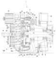
- 2 is a vertical sectional view of the scroll compressor according to the first embodiment shown in FIG. 1 .
- 2 is a side view showing a casing that constitutes a part of the scroll compressor according to the first embodiment shown in FIG. 1
- 4 is a perspective view of a casing of the scroll compressor according to the first embodiment shown in FIG. 3, as viewed from one axial side.
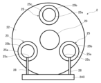
- FIG. 4 is a perspective view of a casing of the scroll compressor according to the first embodiment shown in FIG. 3, as viewed from the other axial side.
- 3A and 3B are diagrams illustrating an excitation force (cause of vibration) acting on the scroll compressor according to the first embodiment.
- FIG. 6 is a side view showing a casing that constitutes a part of a scroll-type fluid machine according to a second embodiment of the present invention.
- FIG. 11 is a bottom view showing a scroll-type fluid machine according to a third embodiment of the present invention.
- FIG. 11 is a schematic diagram showing an example of a leg portion supporting a casing in a scroll-type fluid machine according to another embodiment of the present invention.
- FIG. 11 is a schematic diagram showing an example of an arrangement of bearing bosses of a casing in a scroll-type fluid machine according to another embodiment of the present invention.
- Fig. 1 is a perspective view showing the appearance of a scroll compressor as a scroll type fluid machine according to the first embodiment.
- Fig. 2 is a vertical sectional view of the scroll compressor according to the first embodiment shown in Fig. 1.
- scroll compressor 1 as a scroll type fluid machine is, for example, a scroll type air compressor, and is fixed to an installation surface 100.
- Scroll compressor 1 includes a casing 2 that is open on one axial side (left side in FIG. 2), a fixed scroll 3 fixed to the open side of casing 2, an orbiting scroll 4 housed in casing 2 facing fixed scroll 3, a drive shaft 5 that drives orbiting scroll 4, and a rotation prevention mechanism 6 that prevents orbiting scroll 4 from rotating.
- Drive shaft 5 is rotatably supported by casing 2 via bearings 7 and 8, and is connected to orbiting scroll 4 via orbiting bearing 9.
- rotation prevention mechanism 6 is composed of multiple auxiliary crank mechanisms.
- the casing 2 forms the outer shell of the scroll compressor 1 and has a storage space that houses the orbiting scroll 4 and multiple auxiliary crank mechanisms 6 (only one is shown in FIG. 2). The configuration and structure of the casing 2 will be described in detail later.
- the fixed scroll 3 is attached to the opening end (left end in FIG. 2) of the casing 2's accommodating cylindrical portion 21, which will be described later.
- the fixed scroll 3 has a substantially circular mirror plate 31, a spiral wrap 32 erected on the first surface of the mirror plate 31, which is the surface facing the orbiting scroll 4 (right side in FIG. 2), a heat dissipation fin 33 erected on the second surface of the mirror plate 31, which is the surface opposite the first surface (left side in FIG. 2), and an attachment support portion 34 that is provided on the outer peripheral edge of the mirror plate 31 so as to surround the wrap 32 from the radial outside and is attached to the flange surface of the opening end of the casing 2 (accommodating cylindrical portion 21, which will be described later).
- the fixed scroll 3 is arranged so that its center coincides with the center line O1, which will be described later, of the drive shaft 5.
- the orbiting scroll 4 is arranged in the casing 2 (the accommodating cylindrical portion 21 described later) so as to be rotatable in the axial direction opposite to the fixed scroll 3.
- the orbiting scroll 4 has a substantially circular mirror plate 41, a spiral wrap 42 erected on a first surface of the mirror plate 41 that faces the fixed scroll 3 (left side in FIG. 2), a heat dissipation fin 43 erected on a second surface of the mirror plate 41 that faces the opposite side to the first surface (right side in FIG. 2), and a connection plate 44 attached to the tip side of the heat dissipation fin 43.
- the connection plate 44 is a part that connects the orbiting scroll 4 to the drive shaft 5, and has a cylindrical first bearing boss 46 that houses (places) the orbiting bearing 9.
- connection plate 44 further has a cylindrical second bearing boss 47 that houses (places) a scroll side bearing 61 of the auxiliary crank mechanism 6 described later.
- the first bearing boss 46 is disposed so that its center is radially eccentric by a predetermined dimension (turning radius) set in advance with respect to a center line O1 (described later) of the drive shaft 5.
- Multiple second bearing bosses 47 are disposed at intervals in the circumferential direction of the connection plate 44 according to the arrangement of the multiple auxiliary crank mechanisms 6.
- the fixed scroll 3 and the orbiting scroll 4 are arranged so that their wraps 32, 42 overlap when viewed from the radial direction.
- the spaces sandwiched between the opposing mirror plate 31 of the fixed scroll 3 and mirror plate 41 of the orbiting scroll 4, and the wraps 32 of the fixed scroll 3 and wraps 42 of the orbiting scroll 4 that overlap in the radial direction, are formed as multiple compression chambers C.
- a groove 32a is provided at the tip of the wrap 32 of the fixed scroll 3, and a chip seal 36 is disposed in the groove 32a of the wrap 32.
- a groove 42a is provided at the tip of the wrap 42 of the orbiting scroll 4, and a chip seal 49 is disposed in the groove 42a of the wrap 42.
- a circular groove 34a is provided in the portion of the mounting support 34 of the fixed scroll 3 that faces the end plate 41 of the orbiting scroll 4 (the portion radially outward from the outermost periphery of the multiple compression chambers C), and a circular face seal 37 is disposed in the groove 34a of the mounting support 34.
- the face seal 37 slides relative to the end plate 41 of the orbiting scroll 4 to prevent dust from entering the compression chambers C.
- an intake passage 11 is formed for drawing gas into the compression chamber C.
- one intake passage 11 is disposed on the upper side of the fixed scroll 3.
- An intake filter 12 is disposed at the inlet of the intake passage 11.
- a discharge port 13 for discharging compressed gas is formed in the radial center of the end plate 31 of the fixed scroll 3.
- a discharge pipe 14 is connected to the discharge port 13 to guide the compressed gas to a storage tank (not shown) or the like.
- the drive shaft 5 transmits the rotational power of a rotary drive source (not shown) such as an electric motor to the orbiting scroll 4.
- the drive shaft 5 has a shaft body 51 rotatably supported by bearings 7 and 8, and a crank 52 integrally provided at one end (left end in FIG. 2) of the shaft body 51.
- the shaft body 51 is configured to rotate around a center line O1, and the other axial side (right side in FIG. 2) opposite to the position of the crank 52 protrudes outside the casing 2 and is connected to a rotary drive source (not shown).
- the crank 52 is formed so that its center line O2 is radially eccentric by a predetermined dimension (orbiting radius) set in advance with respect to the center line O1 of the shaft body 51.
- the crank 52 is provided with a balance weight 53 for stabilizing the orbiting operation of the orbiting scroll 4.
- the drive shaft 5 and the balance weight 53 rotate integrally.
- the crank portion 52 of the drive shaft 5 is connected to an orbiting bearing 9 housed in a first bearing boss 46 in the connection plate 44 of the orbiting scroll 4.
- the rotation of the drive shaft 5 is converted into orbital motion of the orbiting scroll 4 via the orbiting bearing 9 due to the eccentricity of the center O2 of the crank portion 52 relative to the center line O1 of the shaft body portion 51.
- the orbiting bearing 9 supports the orbiting scroll 4 so that it can orbit, and ensures that the orbiting scroll 4 orbits with a predetermined orbital radius relative to the center line O1 of the drive shaft 5.
- the multiple auxiliary crank mechanisms 6 serving as rotation prevention mechanisms are interposed between the orbiting scroll 4 and the casing 2, and are spaced apart in the circumferential direction of the orbiting scroll 4.
- the multiple auxiliary crank mechanisms 6 are arranged in the casing 2 at a position closer to a bottom 22 (described later) of the casing 2 than the orbiting scroll 4 (on the rear side opposite the facing side of the fixed scroll 3).
- the rotation prevention mechanism is composed of, for example, three auxiliary crank mechanisms 6, and is arranged at equal intervals of approximately 120° in the circumferential direction (see the bearing bosses 25 for the auxiliary crank mechanisms 6 in Figures 4 and 5 described later). At least three auxiliary crank mechanisms 6 must be arranged in order to provide a rotation prevention function that also serves as a thrust load support.
- the auxiliary crank mechanism 6 has a scroll-side bearing 61 disposed on the orbiting scroll 4 side, a casing-side bearing 62 disposed on the casing 2 side, and an auxiliary crank 63 connected to the scroll-side bearing 61 at one end and to the casing-side bearing 62 at the other end.
- the scroll-side bearing 61 is accommodated in a second bearing boss 47 in the connection plate 44 of the orbiting scroll 4.
- the casing-side bearing 62 is accommodated in a bearing boss 25 of the casing 2, which will be described later.
- the auxiliary crank mechanisms 6 have one end of each auxiliary crank 63 connected to the orbiting scroll 4 via the scroll-side bearing 61, and the other end of each auxiliary crank 63 connected to the casing 2 via the casing-side bearing 62.
- the auxiliary crank mechanisms 6 In addition to the function of preventing the orbiting scroll 4 from rotating, the auxiliary crank mechanisms 6 have the function of receiving the thrust load from the orbiting scroll 4 on the casing 2 (bottom 22, described later) side
- a pulley 16 is provided on the portion of the drive shaft 5 that protrudes outside the casing 2 (the other end of the shaft body 51 located opposite the crank portion 52).
- a belt (not shown) is stretched between the pulley 16 of the scroll compressor 1 and a pulley (not shown) provided on the rotary drive source side.
- the rotary drive force of the rotary drive source is transmitted to the drive shaft 5 via the pulley 16, causing the drive shaft 5 to rotate, and the orbiting scroll 4 to orbit relative to the fixed scroll 3.
- the drive shaft 5 of the scroll compressor 1 and the rotary shaft of the rotary drive source can be connected using a coupling or the like instead of the pulley 16 and belt described above, or the two shafts can be integrated.
- a cooling fan 17 is attached to the other end (right end in FIG. 2) of the drive shaft 5, which is located opposite the crank portion 52.
- the cooling fan 17 is configured to rotate integrally with the drive shaft 5.
- the cooling air generated by the cooling fan 17 is supplied to the fixed scroll 3 and the orbiting scroll 4 via a fan duct 18.
- the fan duct 18 extends from the cooling fan 17 to a position radially outward of the fixed scroll 3 and the orbiting scroll 4.
- the fan duct 18 has a throttling section (not shown) near the opposing position of the fixed scroll 3 and the orbiting scroll 4, and is configured to split the cooling air between the fixed scroll 3 side and the orbiting scroll 4 side due to the fluid resistance of the throttling section.
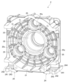
- FIG. 3 is a side view showing a casing constituting a part of the scroll compressor according to the first embodiment shown in Fig. 1.
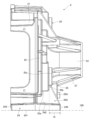
- Fig. 4 is a perspective view of the casing of the scroll compressor according to the first embodiment shown in Fig. 3, viewed from one axial side.
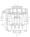
- Fig. 5 is a perspective view of the casing of the scroll compressor according to the first embodiment shown in Fig. 3, viewed from the other axial side.
- the casing 2 of the scroll compressor 1 is formed as a bottomed cylindrical body that is open on one axial side (the left side in Figure 2, the front side of the paper in Figure 4) and closed on the other axial side (the right side in Figure 2, the front side of the paper in Figure 5).
- the casing 2 has a storage cylindrical portion 21 that is open on one axial side, an annular bottom portion 22 that is integrally formed with the end portion on the other axial side of the storage cylindrical portion 21 and extends radially inward, and a cylindrical bearing mounting portion 23 that extends in the axial direction (left and right directions in Figures 2 and 4) from the inner peripheral portion of the bottom portion 22 toward the opposite side of the storage cylindrical portion 21.
- the casing 2 is provided with legs 24 for fixing the casing 2 (scroll compressor 1) to the installation surface 100. As shown in FIG. 2, the legs 24 support the casing 2 so that the axial direction (center line O1) of the drive shaft 5 is parallel to the installation surface 100.
- the orbiting scroll 4 is disposed inside the accommodating cylindrical portion 21, and the crank portion 52 of the drive shaft 5 and the balance weight 53 are also disposed inside the accommodating cylindrical portion 21.
- multiple auxiliary crank mechanisms 6 are interposed between the connection plate 44 (back surface) of the orbiting scroll 4 inside the accommodating cylindrical portion 21 and the bottom portion 22 of the casing 2.
- the bottom 22 of the casing 2 is provided with bearing bosses 25 that house the casing-side bearings 62 of the auxiliary crank mechanisms 6.
- the bearing bosses 25 are arranged at intervals in the circumferential direction on the bottom 22 of the casing 2 according to the arrangement of the auxiliary crank mechanisms 6.
- the rotation prevention mechanism is composed of three auxiliary crank mechanisms 6, as shown in Figures 4 and 5, three bearing bosses 25 are arranged at a predetermined interval in the circumferential direction.
- the bearing bosses 25 are arranged, for example, at a first position located directly above the bearing attachment portion 23 (drive shaft 5) and at a second position located below the bearing attachment portion 23 (drive shaft 5) and on both the left and right sides of the bearing attachment portion 23 (drive shaft 5) when viewed from the axial direction of the drive shaft 5.
- the bearing boss 25, as shown in Figs. 1, 3, and 5, has a shape that bulges from the bottom 22 in the axial direction of the drive shaft 5.
- the bearing boss 25 has an outer peripheral surface 25a and an end surface 25b that constitute a part of the outer surface of the casing 2.
- the outer peripheral surface 25a of the bearing boss 25 is located radially outside the casing side bearing 62 of the auxiliary crank mechanism 6, and is a surface that faces the radially outward direction of the casing side bearing 62.
- the end surface 25b of the bearing boss 25 extends from the periphery of the outer peripheral surface 25a to the radially inward direction of the casing side bearing 62, and is a surface that faces the axial direction of the casing side bearing 62 (drive shaft 5).
- the end surface 25b of the bearing boss 25 has an opening 25c that allows access to the casing side bearing 62.
- the opening 25c of the bearing boss 25 is closed by a plug 26, as shown in Fig. 2.
- the bearing attachment portion 23 has a bearing 7 disposed on one axial side (left side in FIG. 2) and a bearing 8 disposed on the other axial side (right side in FIG. 2).
- the bearing attachment portion 23 rotatably accommodates and supports the shaft body portion 51 of the drive shaft 5 via the bearings 7 and 8.
- the legs 24 are disposed on the radially outer edge of the accommodating tubular portion 21 (casing 2).
- the legs 24 can be, for example, configured as an integral structure with the accommodating tubular portion 21 or can be attached to the accommodating tubular portion 21 by welding or the like.
- the legs 24 are thick plate-like members extending along the axial direction of the drive shaft 5, and are disposed on both the left and right sides of the outer peripheral edge of the accommodating tubular portion 21 when viewed from the axial direction of the drive shaft 5.
- the legs 24 are positioned so that the bearing boss 25 is located approximately directly above them.
- the leg 24 has a bottom surface 241 that contacts the installation surface 100, an upper surface 242 facing the opposite side of the bottom surface 241, a first end surface 243 on one axial side (left side in FIGS. 1 and 3) facing in the opposite direction to the end surface 25b of the bearing boss 25, and a second end surface 244 on the other axial side (right side in FIGS. 1 and 3) facing in the same direction as the end surface 25b of the bearing boss 25.
- the first end surface 243 and the second end surface 244 are provided with notches for attaching fastening members (such as bolts) for fixing the scroll compressor 1 (casing 2) to the installation surface 100.
- the casing 2 provided with the legs 24 is provided with a first reinforcing rib 27 extending from the legs 24 to the bearing attachment portion 23, and a second reinforcing rib 28 extending from the legs 24 to the bearing boss 25.
- the first reinforcing rib 27 and the second reinforcing rib 28 improve the rigidity of both the casing 2 and the legs 24.
- the first reinforcing rib 27 and the second reinforcing rib 28 can be integral with the casing 2 and the legs 24, or can be attached to the casing 2 and the legs 24 by welding or other methods.
- the first reinforcing rib 27 extends along the extension direction of the bearing mounting portion 23 (axial direction of the drive shaft 5) and extends from the leg 24 to the bearing mounting portion 23 so as to connect to the inner side surface of the leg 24 and the outer peripheral surface of the bearing mounting portion 23.
- the first reinforcing rib 27 extends from the outer peripheral surface of the bearing mounting portion 23 radially outward from the bearing mounting portion 23 and is connected to the leg 24.
- the first reinforcing rib 27 is intended to increase the radial rigidity of the bearing mounting portion 23 of the casing 2.
- the second reinforcing rib 28 is intended to suppress axial vibration of the casing 2 with the leg 24 (described below) as a fulcrum, and is configured to extend along the axial direction of the drive shaft 5 on the leg 24 as shown in Figures 1, 3, and 5.
- the second reinforcing rib 28 extends from the position of the bottom 22 of the casing 2 in the axial direction on the upper surface 242 of the leg 24 to the position of the second end surface 244 of the leg 24, for example as shown in Figures 1 and 3.
- the second reinforcing rib 28 is configured to extend from each leg 24 to the bearing boss 25 closest to each leg 24.
- the second reinforcing rib 28 extends from the leg 24 to the bearing boss 25 so as to connect to the upper surface 242 of the leg 24 and the outer peripheral surface 25a and end surface 25b of the bearing boss 25.
- the second reinforcing rib 28 is erected so as to be approximately perpendicular to the upper surface 242 of the leg 24, as shown in FIG. 5, for example, and extends to the bearing boss 25 located approximately directly above the leg 24.
- the second reinforcing rib 28 extends from the leg 24 to the outer peripheral surface 25a of the bearing boss 25 so as to be the shortest distance.
- the second reinforcing rib 28 has a constant thickness, for example.
- the axial tip edge 29 of the second reinforcing rib 28 has a bent shape formed by two sides, for example as shown in Fig. 3.
- the axial tip edge 29 of the second reinforcing rib 28 is formed by a linear first tip edge 291 that rises from the upper surface 242 of the leg 24 so as to be perpendicular to the axial direction of the drive shaft 5, and a linear second tip edge 292 that is inclined relative to the first tip edge 291 so as to connect the end of the first tip edge 291 and the end face 25b of the bearing boss 25.
- Figure 6 is a diagram that explains the excitation force (cause of vibration) that acts on the scroll compressor according to the first embodiment.
- the driving force of a rotary drive source (not shown) is transmitted to the drive shaft 5 via a pulley 16 to drive the orbiting scroll 4.
- the orbiting scroll 4 orbits relative to the fixed scroll 3 by the crank portion 52 of the drive shaft 5 in a state where its rotation is restricted by a plurality of auxiliary crank mechanisms 6.
- gas loads act on the orbiting scroll 4 in the tangential, radial, and axial directions from the compressed air.
- centrifugal force radial force
- a load due to the driving force of the rotational drive source acts on the drive shaft 5 via the pulley 16.
- the load acting on the orbiting scroll 4 is transmitted to the bottom 22 of the casing 2 via the auxiliary crank mechanism 6 (orbiting scroll side bearing 61, auxiliary crank 63, and casing side bearing 62).
- the load acting on the drive shaft 5 is transmitted to the bearing mounting portion 23 of the casing 2 via bearings 7 and 8.
- vibrations occur in the casing 2 of the scroll compressor 1 as the load acting on the orbiting scroll 4 is transmitted via the auxiliary crank mechanism 6, and the load acting on the drive shaft 5 is transmitted via the bearings 7 and 8.
- the main factor in vibration of the casing 2 was a vibration mode in which the casing 2 oscillates in the radial direction due to the load caused by the driving force of the rotary drive source and the orbiting motion of the orbiting scroll 4.
- the analysis results show that the main vibration of the casing 2 is a vibration mode in which the casing 2 oscillates in the forward and backward directions about the legs 24 fixed to the installation surface 100 as shown in FIG. 3.
- a scroll compressor 1 configured in this way, it is necessary to reduce not only the radial vibration components generated in the casing 2, but also the axial vibration components.
- a second reinforcing rib 28 is provided that increases the rigidity of each leg 24 in the axial direction of the scroll compressor 1.
- the second reinforcing rib 28 extends in the axial direction on the leg 24 and also extends from the leg 24 to the bearing boss 25 so as to connect the leg 24 to the outer peripheral surface 25a and end face 25b of the bearing boss 25.
- Axial deformation is suppressed by improving the rigidity of the leg 24.
- axial deformation is suppressed by improving the rigidity of the end face 25b of the bearing boss 25.
- the bearing boss 25 houses the casing side bearing 62 of the auxiliary crank mechanism 6 that has the function of receiving the thrust load from the orbiting scroll 4, and therefore can suppress excitation of a vibration mode in which the casing 2 oscillates in the forward and backward directions with the leg 24 as a fulcrum.
- the rotation prevention mechanism 6 is composed of a plurality of auxiliary crank mechanisms interposed between the orbiting scroll 4 and the casing 2 and arranged at intervals in the circumferential direction of the orbiting scroll 4, and each of the auxiliary crank mechanisms 6 has a scroll-side bearing 61 (first bearing) arranged on the orbiting scroll 4 side, a casing-side bearing 62 (second bearing) arranged on the casing 2 side, and an auxiliary crank 63 connected to the scroll-side bearing 61 (first bearing) and connected to the casing-side bearing 62 (second bearing) on the other side.
- the casing 2 includes a bearing boss 25 that houses the casing-side bearing 62 (second bearing), and the bearing boss 25 has an outer peripheral surface 25a that constitutes a part of the outer surface of the casing 2 and is located radially outward of the casing-side bearing 62 (second bearing), and an end surface 25b that constitutes a part of the outer surface of the casing 2 and extends radially inward from the periphery of the outer peripheral surface 25a and faces the axial direction.
- the second reinforcing rib 28 extends from the leg 24 to the bearing boss 25 so as to connect the leg 24 to the outer peripheral surface 25a and end surface 25b of the bearing boss 25.
- the second reinforcing rib 28 (reinforcing rib) extending in the axial direction extends from the leg 24 to the bearing boss 25 so as to connect to the leg 24 and the outer peripheral surface 25a and end surface 25b of the bearing boss 25, thereby increasing the rigidity of the leg 24 and the bearing boss 25 in the axial direction. Therefore, the axial vibration of the casing 2 with the leg 24 as the fulcrum can be suppressed.
- the auxiliary crank mechanism 6 including the casing side bearing 62 (second bearing) housed in the bearing boss 25 has the function of receiving the thrust load acting on the orbiting scroll 4, so that the rigidity of the end surface 25b of the bearing boss 25 is increased to suppress axial deformation, thereby suppressing the axial vibration of the casing 2.
- the second reinforcing rib 28 (reinforcing rib) is configured to extend to the tip of the leg 24 on the axial side of the bearing boss 25.
- the axial length of the second reinforcing rib 28 (reinforcing rib) on the leg 24 is the longest, so the axial rigidity of the leg 24 can be further increased. Therefore, axial vibration of the casing 2 with the leg 24 as a fulcrum can be further suppressed.
- the axial tip edge 29 of the second reinforcing rib 28 (reinforcing rib) is composed of a linear first tip edge 291 that rises perpendicular to the axial direction from the leg 24, and a linear second tip edge 292 that is inclined relative to the first tip edge 291 so as to connect the end of the first tip edge 291 and the end face 25b of the bearing boss 25.
- the second tip edge 292 which is inclined relative to the first tip edge 291, makes it possible to suppress deterioration of maintainability, such as deterioration of access to the bearing boss 25, which is caused by the installation of the second reinforcing rib 28 (reinforcing rib).
- the casing 2 has a storage tubular portion 21 (storage portion) in which the orbiting scroll 4 is disposed, and an annular bottom portion 22 provided at one axial end of the storage tubular portion 21 (storage portion) and with a bearing boss 25 disposed circumferentially.
- the legs 24 are configured to be disposed on both the left and right sides of the radial outer edge of the storage tubular portion 21 (storage portion) when viewed from the axial direction. When the legs 24 are positioned on the lower side, one bearing boss is disposed directly above the legs 24, and the second reinforcing rib 28 (reinforcing rib) extends from the legs 24 to the outer peripheral surface 25a of the bearing boss 25 at the shortest distance.
- the volume of the second reinforcing rib 28 (reinforcing rib) is reduced, which makes it possible to suppress the increase in weight due to the second reinforcing rib 28 (reinforcing rib) and also to suppress the deterioration of maintainability due to the placement of the second reinforcing rib 28 (reinforcing rib).
- Fig. 7 is a side view showing a casing that constitutes a part of the scroll type fluid machine according to the second embodiment.
- the scroll type fluid machine according to the second embodiment differs from the scroll compressor according to the first embodiment (see FIG. 3) in that the shape of the second reinforcing rib 28A is different.
- the rest of the structure of the scroll type fluid machine according to the second embodiment is similar to that of the first embodiment, and a description thereof will be omitted.
- the second reinforcing rib 28A shown in FIG. 7 extends from the position of the bottom 22 of the casing 2 in the axial direction on the upper surface 242 of the leg 24 to the position of the second end surface 244 of the leg 24, similar to the second reinforcing rib 28 of the first embodiment. Also, the second reinforcing rib 28A extends from each leg 24 to the bearing boss 25 so as to be connected to the upper surface 242 of each leg 24 and the outer peripheral surface 25a and end surface 25b of the bearing boss 25 closest to each leg 24, similar to the second reinforcing rib 28 of the first embodiment (see FIG. 3).
- the axial tip edge 29A of the second reinforcing rib 28A has a linear shape formed by one side, unlike the second reinforcing rib 28 of the first embodiment.
- the tip edge 29A extends from the position of the second end face 244 on the upper surface 242 of the leg 24 to the end face 25b of the bearing boss 25, and is an edge that is inclined with respect to a plane perpendicular to the axial direction.
- the position of the axial tip of the second reinforcing rib 28A on the leg 24 can be set arbitrarily within the range Rt shown in FIG. 7, that is, in the range from a position closer to the second end face 244 than the position of the end face 25b of the bearing boss 25 to the position of the second end face 244.
- the second reinforcing rib 28A can be configured so that the position of the axial tip of the second reinforcing rib 28A on the leg 24 is midway between the position of the second end face 244 of the leg 24 and the axial position of the end face 25b of the bearing boss 25. This is a condition that makes it possible to extend the second reinforcing rib 28A from the leg 24 to the bearing boss 25 so as to be connected to the leg 24 and the end face 25b of the bearing boss 25.
- the second reinforcing rib 28A (reinforcing rib) extending in the axial direction extends from the leg 24 to the bearing boss 25 so as to connect to the outer peripheral surface 25a and end surface 25b of the leg 24 and the bearing boss 25, thereby increasing the rigidity of the leg 24 and the bearing boss 25 in the axial direction. Therefore, axial vibration of the casing 2 with the leg 24 as a fulcrum can be suppressed.
- the second reinforcing rib 28A is configured so that the axial tip position on the leg 24 is midway between the axial tip of the leg 24 and the axial position of the end face 25b of the bearing boss 25.
- the volume of the second reinforcing rib 28A is smaller than that of the second reinforcing rib 28 of the first embodiment, which extends to the axial tip of the leg 24. Therefore, the second reinforcing rib 28A is lighter in weight than the second reinforcing rib 28 of the first embodiment.
- the second reinforcing rib 28A has a shorter axial length than the second reinforcing rib 28 of the first embodiment, which makes it possible to avoid interference with other components and improve workability during assembly.
- the axial tip edge 29A of the second reinforcing rib 28A has a straight line shape formed by one side.
- the volume of the second reinforcing rib 28A is smaller than that of the second reinforcing rib 28 of the first embodiment, in which the axial tip edge 29 has a bent shape formed by two sides. Therefore, the second reinforcing rib 28A is lighter in weight than the second reinforcing rib 28 of the first embodiment. In addition, the second reinforcing rib 28A occupies a smaller area than the second reinforcing rib 28 of the first embodiment, which makes it possible to avoid interference with other components and improve workability during assembly.
- Fig. 8 is a bottom view showing the scroll type fluid machine according to the third embodiment.
- the scroll type fluid machine according to the third embodiment differs from the scroll compressor 1 according to the first embodiment in that the structure of the legs 24B that support the casing 2 is different.
- the rest of the structure of the scroll type fluid machine according to the third embodiment is similar to that of the first embodiment, and a description thereof will be omitted.
- the leg 24B supporting the casing 2 has a plurality of cutouts 241a and one positioning hole 241b on its bottom surface 241.
- the cutouts 241a are recesses formed to a depth that does not penetrate from the bottom surface 241 of the leg 24B to the top surface 242, and are provided in multiple locations to avoid the positioning hole 241b.
- the multiple cutouts 241a are arranged to form lattice-shaped ribs 241c.
- the weight of the leg 24B is reduced by the cutouts 241a.
- the strength reduction of the leg 24B due to the cutouts 241a is suppressed by the ribs 241c formed between the multiple cutouts 241a.
- the bottom surface 241 of the leg 24B is finished to a flat surface to reduce rattling against the installation surface 100.
- the area of the bottom surface 241 that is subjected to finishing processing is reduced. Therefore, the number of steps required for finishing processing can be reduced.
- the leg 24B has a hollowed-out portion 241a on the bottom surface 241 that comes into contact when installed.
- the hollowed-out portion 241a of the leg 24B can reduce the weight of the leg 24B.
- the leg 24B has a plurality of hollowed-out portions 241a, which are arranged so as to define lattice-shaped ribs 241c on the bottom surface 241 of the leg 24B.
- This configuration makes it possible to reduce the weight of the leg 24B and also to suppress the loss of strength that accompanies the weight reduction.
- the present invention is not limited to the above-described embodiment, and includes various modified examples.
- the above-described embodiment has been described in detail to easily explain the present invention, and is not necessarily limited to those having all of the configurations described. It is possible to replace a part of the configuration of one embodiment with the configuration of another embodiment, and it is also possible to add the configuration of another embodiment to the configuration of one embodiment. It is also possible to add, delete, or replace a part of the configuration of each embodiment with another configuration.
- leg 24, 24B supporting the casing 2 are disposed on both the left and right sides of the radially outer edge of the casing 2 when viewed from the axial direction.
- leg 24C can also be configured as a single pedestal disposed on the underside of the casing 2, as shown in Figure 9.
- Figure 9 is a schematic diagram showing an example of legs supporting a casing in a scroll-type fluid machine according to another embodiment of the present invention.
- the second reinforcing rib 28 is configured to extend from the leg 24C to the bearing boss 25 so as to be connected to the outer peripheral surface 25a and end surface 25b of the bearing boss 25 that is closest to the leg 24C among the multiple bearing bosses 25 of the casing 2. Even in this leg 24C, it is possible to suppress axial vibration of the casing 2 with the leg 24B as a fulcrum.
- FIG. 10 is a schematic diagram showing an example of the arrangement of the bearing bosses of the casing in a scroll-type fluid machine according to another embodiment of the present invention.
- the bottom 22 of the casing 2D is provided with two bearing bosses 25D located above the bearing mounting portion 23 and located on both the left and right sides of the bearing mounting portion 23 when viewed from the axial direction, and one bearing boss 25D located below the bearing mounting portion 23 and closest to the two legs 24.
- the second reinforcing rib 28D is configured to be connected from each leg 24 to one of the multiple bearing bosses 25D that is closest to the corresponding leg 24.
- the second reinforcing rib 28D is configured to extend from each leg 24 to the bearing boss 25D so as to be connected to the upper surface 242 of each leg 24 and the outer circumferential surface 25a and end surface 25b of one bearing boss 25D located below the bearing mounting portion 23.
- the rigidity of the leg 24 and the bearing boss 25D can be increased in the axial direction by extending the second reinforcing rib 28D (reinforcing rib) from the leg 24 to the bearing boss 25D so as to connect to the leg 24 and the outer peripheral surface 25a and end surface 25b of the bearing boss 25D. Therefore, the axial vibration of the casing 2D with the leg 24 as the fulcrum can be suppressed.
- 1...Scroll compressor (scroll type fluid machine), 2, 2D...Casing, 4...Orbiting scroll, 5...Drive shaft, 6...Auxiliary crank mechanism (rotation prevention mechanism), 21...Accommodating tubular part (accommodating part), 22...Bottom, 24, 24B, 24C...Leg, 241...Bottom surface, 241a...Lightening part, 241c...Rib, 25, 25D...Bearing boss, 25a...Outer periphery, 25b...End surface, 28, 28A, 28D...Second reinforcing rib (reinforcing rib), 29, 29A...Tip edge, 291...First tip edge, 292...Second tip edge, 61...Scroll side bearing (first bearing), 62...Casing side bearing (second bearing), 63...Auxiliary crank
Landscapes
- Engineering & Computer Science (AREA)
- Mechanical Engineering (AREA)
- General Engineering & Computer Science (AREA)
- Rotary Pumps (AREA)
Priority Applications (5)
| Application Number | Priority Date | Filing Date | Title |
|---|---|---|---|
| JP2025509246A JP7830764B2 (ja) | 2023-03-24 | 2023-03-24 | スクロール式流体機械 |
| EP23930251.6A EP4692552A1 (en) | 2023-03-24 | 2023-03-24 | Scroll-type fluid machine |
| US19/104,732 US20260055766A1 (en) | 2023-03-24 | 2023-03-24 | Scroll-Type Fluid Machine |
| PCT/JP2023/011992 WO2024201610A1 (ja) | 2023-03-24 | 2023-03-24 | スクロール式流体機械 |
| CN202380060710.0A CN119731435A (zh) | 2023-03-24 | 2023-03-24 | 涡旋式流体机械 |
Applications Claiming Priority (1)
| Application Number | Priority Date | Filing Date | Title |
|---|---|---|---|
| PCT/JP2023/011992 WO2024201610A1 (ja) | 2023-03-24 | 2023-03-24 | スクロール式流体機械 |
Publications (1)
| Publication Number | Publication Date |
|---|---|
| WO2024201610A1 true WO2024201610A1 (ja) | 2024-10-03 |
Family
ID=92904110
Family Applications (1)
| Application Number | Title | Priority Date | Filing Date |
|---|---|---|---|
| PCT/JP2023/011992 Ceased WO2024201610A1 (ja) | 2023-03-24 | 2023-03-24 | スクロール式流体機械 |
Country Status (5)
| Country | Link |
|---|---|
| US (1) | US20260055766A1 (https=) |
| EP (1) | EP4692552A1 (https=) |
| JP (1) | JP7830764B2 (https=) |
| CN (1) | CN119731435A (https=) |
| WO (1) | WO2024201610A1 (https=) |
Citations (4)
| Publication number | Priority date | Publication date | Assignee | Title |
|---|---|---|---|---|
| JPH10506161A (ja) * | 1994-04-05 | 1998-06-16 | ネルコー ピューリタンベネット インコーポレイテッド | スクロール圧縮機 |
| JP2008202522A (ja) | 2007-02-21 | 2008-09-04 | Mitsubishi Heavy Ind Ltd | 圧縮機 |
| JP2012196045A (ja) * | 2011-03-16 | 2012-10-11 | Yazaki Corp | 固定脚構造及び電気接続箱の固定脚構造 |
| WO2016038694A1 (ja) * | 2014-09-10 | 2016-03-17 | 株式会社日立産機システム | スクロール式流体機械 |
-
2023
- 2023-03-24 JP JP2025509246A patent/JP7830764B2/ja active Active
- 2023-03-24 US US19/104,732 patent/US20260055766A1/en active Pending
- 2023-03-24 WO PCT/JP2023/011992 patent/WO2024201610A1/ja not_active Ceased
- 2023-03-24 CN CN202380060710.0A patent/CN119731435A/zh active Pending
- 2023-03-24 EP EP23930251.6A patent/EP4692552A1/en active Pending
Patent Citations (4)
| Publication number | Priority date | Publication date | Assignee | Title |
|---|---|---|---|---|
| JPH10506161A (ja) * | 1994-04-05 | 1998-06-16 | ネルコー ピューリタンベネット インコーポレイテッド | スクロール圧縮機 |
| JP2008202522A (ja) | 2007-02-21 | 2008-09-04 | Mitsubishi Heavy Ind Ltd | 圧縮機 |
| JP2012196045A (ja) * | 2011-03-16 | 2012-10-11 | Yazaki Corp | 固定脚構造及び電気接続箱の固定脚構造 |
| WO2016038694A1 (ja) * | 2014-09-10 | 2016-03-17 | 株式会社日立産機システム | スクロール式流体機械 |
Also Published As
| Publication number | Publication date |
|---|---|
| JPWO2024201610A1 (https=) | 2024-10-03 |
| JP7830764B2 (ja) | 2026-03-16 |
| CN119731435A (zh) | 2025-03-28 |
| EP4692552A1 (en) | 2026-02-11 |
| US20260055766A1 (en) | 2026-02-26 |
Similar Documents
| Publication | Publication Date | Title |
|---|---|---|
| JP6587636B2 (ja) | 電動スクロール圧縮機 | |
| EP3926171B1 (en) | Scroll compressor, vehicle air conditioner and vehicle | |
| JP7620557B2 (ja) | スクロール圧縮機 | |
| JPH04365902A (ja) | スクロール型流体機械 | |
| US5435707A (en) | Scroll-type compressor with an elastically deformable top plate or end plate | |
| US4512729A (en) | Drive bearing device for a fluid displacement apparatus | |
| US20190376514A1 (en) | Compressor | |
| US7559750B2 (en) | Overheating protection apparatus of scroll compressor | |
| US6190147B1 (en) | Rotation balancing mechanism for orbiting scrolls of scroll-type compressors | |
| WO2024201610A1 (ja) | スクロール式流体機械 | |
| CN107882738B (zh) | 压缩机 | |
| KR20040007673A (ko) | 밀폐형 압축기 | |
| CN115126694B (zh) | 电动压缩机 | |
| JP7267119B2 (ja) | クランクシャフト、及びロータリ圧縮機 | |
| JP2006017013A (ja) | スクロール式流体機械 | |
| JP2011231687A (ja) | スクロール圧縮機 | |
| JP5409065B2 (ja) | 圧縮機 | |
| JP2025514483A (ja) | スパイラル原理に基づく容積型機械 | |
| JP2023004889A (ja) | スクロール圧縮機 | |
| JPH04234591A (ja) | スクロ−ル形圧縮機 | |
| WO2024042984A1 (ja) | スクロール圧縮機 | |
| JP2025144863A (ja) | スクロール圧縮機 | |
| JP2004263604A (ja) | スクロール式流体機械 | |
| KR20250044559A (ko) | 스크롤 압축기 | |
| JPH051503A (ja) | スクロール式流体機械 |
Legal Events
| Date | Code | Title | Description |
|---|---|---|---|
| 121 | Ep: the epo has been informed by wipo that ep was designated in this application |
Ref document number: 23930251 Country of ref document: EP Kind code of ref document: A1 |
|
| WWE | Wipo information: entry into national phase |
Ref document number: 2025509246 Country of ref document: JP |
|
| WWE | Wipo information: entry into national phase |
Ref document number: 202380060710.0 Country of ref document: CN |
|
| WWE | Wipo information: entry into national phase |
Ref document number: 202517022342 Country of ref document: IN |
|
| WWP | Wipo information: published in national office |
Ref document number: 202517022342 Country of ref document: IN Ref document number: 202380060710.0 Country of ref document: CN |
|
| WWE | Wipo information: entry into national phase |
Ref document number: 2023930251 Country of ref document: EP |
|
| NENP | Non-entry into the national phase |
Ref country code: DE |
|
| ENP | Entry into the national phase |
Ref document number: 2023930251 Country of ref document: EP Effective date: 20251024 |
|
| ENP | Entry into the national phase |
Ref document number: 2023930251 Country of ref document: EP Effective date: 20251024 |
|
| ENP | Entry into the national phase |
Ref document number: 2023930251 Country of ref document: EP Effective date: 20251024 |
|
| ENP | Entry into the national phase |
Ref document number: 2023930251 Country of ref document: EP Effective date: 20251024 |
|
| ENP | Entry into the national phase |
Ref document number: 2023930251 Country of ref document: EP Effective date: 20251024 |
|
| ENP | Entry into the national phase |
Ref document number: 2023930251 Country of ref document: EP Effective date: 20251024 |
|
| ENP | Entry into the national phase |
Ref document number: 2023930251 Country of ref document: EP Effective date: 20251024 |
|
| ENP | Entry into the national phase |
Ref document number: 2023930251 Country of ref document: EP Effective date: 20251024 |
|
| WWP | Wipo information: published in national office |
Ref document number: 2023930251 Country of ref document: EP |