WO2024201565A1 - 表示装置 - Google Patents
表示装置 Download PDFInfo
- Publication number
- WO2024201565A1 WO2024201565A1 PCT/JP2023/011809 JP2023011809W WO2024201565A1 WO 2024201565 A1 WO2024201565 A1 WO 2024201565A1 JP 2023011809 W JP2023011809 W JP 2023011809W WO 2024201565 A1 WO2024201565 A1 WO 2024201565A1
- Authority
- WO
- WIPO (PCT)
- Prior art keywords
- screen
- mode
- switch
- displayed
- operated
- Prior art date
- Legal status (The legal status is an assumption and is not a legal conclusion. Google has not performed a legal analysis and makes no representation as to the accuracy of the status listed.)
- Ceased
Links
Images






Classifications
-
- B—PERFORMING OPERATIONS; TRANSPORTING
- B60—VEHICLES IN GENERAL
- B60K—ARRANGEMENT OR MOUNTING OF PROPULSION UNITS OR OF TRANSMISSIONS IN VEHICLES; ARRANGEMENT OR MOUNTING OF PLURAL DIVERSE PRIME-MOVERS IN VEHICLES; AUXILIARY DRIVES FOR VEHICLES; INSTRUMENTATION OR DASHBOARDS FOR VEHICLES; ARRANGEMENTS IN CONNECTION WITH COOLING, AIR INTAKE, GAS EXHAUST OR FUEL SUPPLY OF PROPULSION UNITS IN VEHICLES
- B60K23/00—Arrangement or mounting of control devices for vehicle transmissions, or parts thereof, not otherwise provided for
Definitions
- This case concerns a display device that displays information related to the vehicle's drive mode and driving mode.
- a display device that is applied to a vehicle equipped with a transfer device that changes the drive state of the front and rear wheels, and displays information related to the drive mode and driving mode.
- the drive mode means a mode that is set according to the state of the transfer device.
- the driving mode means a control mode that is set according to the driving conditions of the vehicle.
- Patent Document 1 discloses a display device (display control unit) that displays on the same screen a drive mode selected from among multiple drive modes and a driving mode selected from among multiple driving modes.
- Patent Document 1 describes a technology that allows the driving mode to be set appropriately off-road, and simply displays only the selected drive mode and the selected driving mode.
- recent display devices may display a variety of information in addition to information related to the drive mode and driving mode. Displaying such a variety of information can improve the convenience of the display device.
- the device disclosed in Patent Document 1 has room for improvement in terms of appropriately displaying a variety of information including the drive mode and driving mode.
- This invention was conceived in consideration of these problems, and one of its objectives is to appropriately display a variety of information, including information related to drive modes and driving modes. However, this objective is not the only objective. Another objective of this invention is to achieve effects that cannot be obtained with conventional technology, which are derived from the configurations shown in the "Mode for carrying out the invention" described below.
- the disclosed display device can be realized as the aspects (application examples) disclosed below, which solve at least part of the above problems.
- Each of the aspects from aspect 2 onwards is an aspect that can be selected additionally as appropriate, and each of the aspects can be omitted. None of the aspects from aspect 2 onwards discloses an essential aspect or configuration for the present case.
- the display device disclosed is a display device mounted on a vehicle equipped with a transfer device that changes the drive state of the front and rear wheels, a first switch that switches between a plurality of drive modes corresponding to the operating state of the transfer device to select one, and a second switch that switches between a plurality of driving modes that implement control according to the driving environment to select one, and includes a content screen that displays content information related to the vehicle, a first screen that is switched from the content screen to be displayed when the first switch is operated by an occupant while the content screen is being displayed, and a second screen that is switched from the content screen to be displayed when the second switch is operated by the occupant while the content screen is being displayed.
- the first screen has a status display unit that displays the operating state of the transfer device in a driving mode selected from among the plurality of driving modes.
- the second screen has a driving mode display unit that displays the plurality of driving modes side by side and displays the selected driving mode in a recognizable manner, and a driving mode display unit that displays the driving modes selectable in the selected driving mode side by side and displays the selected driving mode in a recognizable manner.
- the display device displays the second screen when the second switch is operated while the first screen is being displayed, and displays the first screen when the first switch is operated while the second screen is being displayed.
- the vehicle is provided with a third switch that is operated by the occupant.
- the display device displays the content screen when the second switch is not operated again within a predetermined time after the second switch is operated while the second screen is being displayed, and displays the content screen when the first switch is not operated again after the first switch is operated while the first screen is being displayed and switching of the operating state of the transfer device is completed or when the third switch is operated.
- the display device when the display device displays the content screen in response to the operation of the third switch, it is preferable that the display device redisplays the first screen when switching of the operating state of the transfer device is completed, and displays the content screen if the first switch is not operated within the predetermined time after the redisplay or if the third switch is operated.
- the status display unit displays an icon indicating parts including the front wheels and the rear wheels in a lit or unlit state depending on the selected drive mode.
- the icon the display state of which changes before and after the switchover, flashes until the switchover of the operating state of the transfer device is completed, and is displayed in a lit or unlit state after the switchover is completed.
- the first screen has a selected mode display section that displays the selected driving mode.
- the multiple driving modes are provided with a common driving mode that can be selected regardless of the selected drive mode, and it is preferable that when the first switch is operated while the second screen is being displayed, the common driving mode is selected as the selected driving mode while the first screen is being displayed.
- the content screen includes a vehicle status display screen having the status display section and a yaw status display section that displays the status of yaw control for the vehicle.
- the yaw status display section is not displayed on the first screen.
- the disclosed display device can appropriately display a variety of information, including information related to drive modes and driving modes.
- FIG. 1 is a schematic diagram showing a drive system device of a vehicle to which a display device according to an embodiment is applied;
- FIG. 2 is a perspective view showing the periphery of a driver's seat and a passenger seat of the vehicle shown in FIG. 1 .
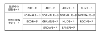
- 4 is a table showing an example of driving modes that can be selected in each drive mode.
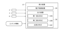
- 1 is a block diagram of a display device according to an embodiment.
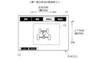
- FIG. 13 is a diagram showing an example of a first screen displayed in a first display format.
- FIG. 13 is a diagram showing another example of the first screen displayed in the first display format.
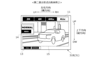
- FIG. 13 is a diagram showing an example of a second screen displayed in a second display format.
- FIG. 13 is a diagram showing another example of the second screen displayed in the second display format.
- FIG. 13 is a diagram showing an example of a content screen displayed in a main display format.
- FIG. 13 is a diagram showing another example of a content screen displayed in the main display format.
- 11A and 11B are diagrams illustrating an example of a flow of switching between a content screen and a first screen.
- FIG. 13A and 13B are diagrams illustrating another example of the flow of switching between the content screen and the first screen.
- 14 is a diagram for explaining the flow of switching between the content screen and the first screen after the flow of FIG. 13.
- FIG. 11A and 11B are diagrams illustrating an example of a flow of switching between a content screen and a second screen.
- FIG. 11 is a diagram for explaining an example of a flow of switching from a first screen to a second screen.
- FIG. 11 is a diagram for explaining an example of a flow for switching from the second screen to the first screen.
- the forward direction of the vehicle is referred to as the forward direction (front of the vehicle), and the opposite direction is referred to as the rearward direction (rear of the vehicle).
- Left and right are defined based on the state in which the vehicle is facing forward.
- the left and right direction is perpendicular to the fore-aft direction of the vehicle.
- the left and right direction is also referred to as the "vehicle width direction”
- the fore-aft direction of the vehicle is simply referred to as the "fore-aft direction”.
- the direction perpendicular to both the vehicle width direction and the fore-aft direction is defined as the up-down direction.
- FR stands for front
- RR stands for rear
- RH stands for right
- LH stands for left
- UP stands for up
- DW stands for down.
- Vehicle configuration] 1 is a schematic diagram showing a drive system (powertrain) of a vehicle 1 according to an embodiment.
- the vehicle 1 is capable of changing the drive state of front wheels FW and rear wheels RW.
- the vehicle 1 is provided with a drive source 4 and a transfer device 5 interposed on a power transmission path between the drive source 4 and the front and rear wheels FW, RW.
- the vehicle 1 may be provided with a transmission AT (automatic transmission) that is connected to the output shaft of the drive source 4 and whose gear ratio is set in response to a shift operation by the driver.
- the vehicle 1 may also be provided with a front differential FD that absorbs the rotation difference between the left and right front wheels FW and distributes and transmits the driving force transmitted from the transfer device 5 to the left and right front wheels FW.
- the vehicle 1 may also be provided with a rear differential RD that absorbs the rotation difference between the left and right rear wheels RW and distributes and transmits the driving force transmitted from the transfer device 5 to the left and right rear wheels RW.
- the transmission AT, front differential FD, and rear differential RD are not essential.
- the driving source 4 is, for example, an internal combustion engine (e.g., a gasoline engine, a diesel engine, etc.) that uses gasoline or diesel as fuel.
- the driving source 4 may also be a motor generator that functions as both an electric motor and a generator.
- the vehicle 1 may be a hybrid vehicle (HEV, Hybrid Electric Vehicle) or a plug-in hybrid vehicle (PHEV, Plug-in Hybrid Electric Vehicle) that has both an internal combustion engine and a motor generator as the driving source 4.
- a plug-in hybrid vehicle is a hybrid vehicle that allows external charging of the battery or external power supply from the battery.
- a plug-in hybrid vehicle is provided with a charging port (inlet) for inserting a charging cable that supplies power from an external charging facility and an outlet (outlet) for external power supply.
- the transfer device 5 is a device that changes (or maintains) the drive state of the front wheels FW and rear wheels RW, and includes a center differential 5A (hereafter referred to as "center differential 5A") and a switching mechanism 5B.
- the transfer device 5 of this embodiment further includes a locking mechanism 5C that locks the differential of the center differential 5A, and a sub-transmission mechanism 5D that changes the drive force input to the center differential 5A.
- the center differential 5A absorbs the difference in rotation between the front wheels FW and the rear wheels RW and distributes and transmits driving force.
- the center differential 5A is composed of, for example, a planetary gear mechanism.
- the switching mechanism 5B switches the connection state between the center differential 5A and the front wheels FW.
- the switching mechanism 5B is composed of, for example, multiple clutch gears and coupling sleeves connected to the center differential 5A.
- the switching mechanism 5B disconnects the center differential 5A from the front wheels FW, thereby realizing a two-wheel drive state (2H state) in which only the rear wheels RW are driven as drive wheels. Also, the switching mechanism 5B connects the center differential 5A to the front wheels FW, thereby absorbing the rotational difference between the front wheels FW and the rear wheels RW, and realizing a four-wheel drive state (4H state) in which both the front wheels FW and the rear wheels RW are driven as drive wheels.
- the locking mechanism 5C locks the differential of the center differential 5A when the center differential 5A and the front wheels FW are connected by the switching mechanism 5B.
- the locking mechanism 5C is composed of, for example, multiple clutch gears and a coupling sleeve connected to the center differential 5A.
- the sub-transmission mechanism 5D is a high/low switching mechanism that changes the driving force input to the center differential 5A (changes the rotation) when the differential of the center differential 5A is locked by the locking mechanism 5C.
- the sub-transmission mechanism 5D is composed of, for example, multiple gears, a countershaft, and a coupling sleeve.
- the sub-transmission mechanism 5D has a high gear position and a low gear position, and the high gear position and the low gear position are switched by changing the meshing of the elements that make up the sub-transmission mechanism 5D.
- the differential of the center differential 5A is locked by the lock mechanism 5C, and the sub-transmission mechanism 5D is placed in the high gear position, thereby realizing a four-wheel drive state (4HLc state) that is different from the 4H state.
- 4HLc state the rotation input to the sub-transmission mechanism 5D is directly transmitted to the center differential 5A.
- the rotation (driving force) transmitted to the center differential 5A is not differentially distributed, but is equally distributed to the front wheels FW and rear wheels RW, and both the front wheels FW and rear wheels RW are driven as drive wheels.
- the differential of the center differential 5A is locked by the lock mechanism 5C, and the sub-transmission mechanism 5D is placed in the low gear position, thereby realizing a four-wheel drive state (4LLc state) that is different from the 4H state and the 4HLc state.
- 4LLc state unlike the 4HLc state, the rotation input to the sub-transmission mechanism 5D is decelerated and transmitted to the center differential 5A.
- the rotation (driving force) transmitted to the center differential 5A is not differentially distributed, but is equally distributed to the front wheels FW and rear wheels RW, and both the front wheels FW and rear wheels RW are driven as drive wheels.
- Vehicle 1 is provided with multiple drive modes according to the operating state of transfer device 5 described above (i.e., the drive state achieved by transfer device 5), and is also provided with a first switch 2 for switching between the multiple drive modes and selecting one, as shown in FIG. 2.
- Vehicle 1 is further provided with a second switch 3 and a third switch 6.
- Second switch 3 is a switch for setting a driving mode separate from the drive mode. The driving modes will be described later.
- Each of switches 2, 3, and 6 is a physical switch that is operated by an occupant (mainly the driver).
- 2H mode There are four driving modes: 2H mode, 4H mode, 4HLc mode, and 4LLc mode, which correspond to the operating states of the transfer device 5 described above.
- 2H mode the transfer device 5 realizes the 2H state
- 4H mode the transfer device 5 realizes the 4H state
- 4HLc mode the transfer device 5 realizes the 4HLc state
- 4LLc mode the transfer device 5 realizes the 4LLc state.
- the first switch 2 is a drive mode switch that switches between these four drive modes to select one of them.
- the first switch 2 is a rotary switch located on the top surface of the center console 1C.
- the center console 1C is a panel that extends in the front-rear direction and in the vehicle width direction between the driver's seat 1A and the passenger seat 1B.
- the first switch 2 is provided with a disk portion 2A and a frame portion 2B.
- the disk portion 2A is fixed to the center console 1C and is a cylindrical or columnar member with a circular end face that faces in the same direction as the top surface of the center console 1C (i.e., upward).
- the end face of the disk portion 2A is marked with words indicating each drive mode.
- the words "2H” indicating 2H mode, "4H” indicating 4H mode, "4HLc” indicating 4HLc mode, and "4LLc” indicating 4LLc mode are marked in this order from the left in the circumferential direction on the front part of the disk portion 2A.
- the frame 2B is a cylindrical member that surrounds the outer periphery of the disk portion 2A, and is configured to be rotatable counterclockwise or clockwise with respect to the disk portion 2A, as shown by the dashed arrow in Figure 2.
- a scale is engraved at one point on the circumference of the frame 2B.
- the first switch 2 is operated by the occupant when the frame 2B is rotated counterclockwise or clockwise so that the scale on the frame 2B points to one of the words written on the disk portion 2A. This allows one of the four drive modes to be alternatively selected as the "selected drive mode".
- vehicle 1 is provided with multiple driving modes that implement control according to the driving environment of vehicle 1.
- seven driving modes are provided: NORMAL mode, ECO mode, GRAVEL mode, SNOW mode, MUD mode, SAND mode, and ROCK mode.
- NORMAL mode is a mode in which preset standard control is implemented.
- ECO mode is a mode in which control is implemented that places more emphasis on fuel economy and power consumption than NORMAL mode (eco-friendly driving).
- GRAVEL mode is a mode in which control is implemented that is suitable for driving on gravel roads.
- SNOW mode is a mode in which control is implemented that is suitable for driving on snowy roads, and MUD mode is a mode in which control is implemented that is suitable for driving on muddy roads.
- SAND mode is a mode in which control is implemented that is suitable for driving on sand, and ROCK mode is a mode in which control is implemented that is suitable for driving on rocky roads.
- the driving modes are set so that two or more of these seven driving modes can be selected alternatively for each selected drive mode, and one of the selectable driving modes is selected as the "selected driving mode.”
- NORMAL mode is set as a common driving mode that can be selected in any drive mode.
- the on-board devices for example, the drive source 4, the transmission AT, or a braking device (not shown)
- the on-board devices are appropriately controlled according to the selected driving mode.
- the second switch 3 is a driving mode switch that switches between multiple driving modes selectable in the selected drive mode and selects one driving mode.
- the second switch 3 is, for example, a push switch located on the top surface of the center console 1C.
- the second switch 3 is provided with a push button 3A that can be pressed downward.
- the second switch 3 switches the selected driving mode when the occupant presses the push button 3A downward.
- the push button 3A returns to its original position after being pressed.
- the driving operation switch 3 is a momentary push switch.
- the selected driving mode is switched, for example, in accordance with the up and down direction in the table of FIG. 3. For example, if the selected drive mode is "4H mode” and the selected driving mode is "GRAVEL mode”, pressing push button 3A switches the selected driving mode from “GRAVEL mode” to the "SNOW mode” below. Also, if the selected driving mode is "SNOW mode”, pressing push button 3A switches the selected driving mode to "NORMAL mode" in the top row of the "4H mode” column.
- the NORMAL mode which is a common drive mode
- the selected drive mode is selected as the selected drive mode.
- the drive mode selected in the drive mode before the switch is switched to the common drive mode when the drive mode is switched.
- the selected drive mode can be switched (i.e. automatically) even when the second switch 3 is not operated.
- the selected drive mode is automatically switched to the common drive mode, making it easier for the occupant to understand which drive mode is selected after the drive mode is switched.
- the third switch 6 is a switch for switching from a first screen 31A (described later) to a content screen 31C (described later). As shown in FIG. 2, the third switch 6 is, for example, a momentary push switch located on the handle 1H.
- [1-2. Display device] 4 is a block diagram showing a configuration of a display device 10 according to an embodiment.
- the display device 10 displays information about the vehicle 1 including information about the drive mode and the running mode (hereinafter, also referred to as "content information").
- the display screen is switched appropriately in response to the operation of at least the switches 2 and 3.
- the display device 10 has the function of helping the occupant understand each of the drive modes and driving modes while responding to the desire to check a variety of information.
- a first switch 2 and a second switch 3 are connected to the input side of the display device 10.
- a third switch 6 may also be connected to the input side of the display device 10. Operation information of these switches 2, 3, and 6 is transmitted to the display device 10 at any time.
- the content information may include information related to the drive mode and driving mode as well as vehicle speed information of the vehicle 1.
- the content information may also include information related to yaw control (active yaw control (AYC)).
- the content information may include information related to the driving state of the vehicle 1.
- Specific examples of content information related to the driving state of the vehicle 1 include information such as the shift position, the reduction ratio of the AT transmission, driving distance, estimated remaining driving distance, fuel efficiency, electricity efficiency, remaining battery capacity, roll rate, pitch rate, longitudinal acceleration, lateral acceleration, road surface inclination angle, tire pressure, driving direction (azimuth), altitude, temperature, and road surface friction coefficient.
- the content information may include information related to the operating status of the in-vehicle equipment.
- Content information representing the operating status of the in-vehicle equipment may include audio information, car navigation information, lighting status information, cruise control related information, vehicle distance information, various websites, etc.
- the display device 10 may be connected to the smartphone of the occupant (user) and display content information representing the operating status of the smartphone (for example, call information, email sending/receiving information, etc.).
- Information related to the drive mode is generated or acquired, for example, by the first switch 2 and transmitted to the display device 10.
- the information may be generated or acquired by an ECU (not shown) based on operation information of the first switch 2 and transmitted to the display device 10.
- information related to the driving mode is generated or acquired, for example, by the second switch 3 and transmitted to the display device 10.
- the information may be generated or acquired by an ECU (not shown) based on operation information of the second switch 3 and transmitted to the display device 10.
- Other information is generated or acquired, for example, by various ECUs, various in-vehicle devices, various sensors, etc. (none of which are shown) and transmitted to the display device 10.
- the display device 10 comprises an electronic control device 20 and an output device 30.
- the electronic control device 20 is a computer for controlling the content displayed on the output device 30, and has a built-in processor (arithmetic processing unit) and memory (storage device).
- the processing content (program) of the electronic control device 20 is stored in the memory, and is executed by loading the content into the processor as appropriate.
- the electronic control device 20 may be formed integrally with the output device 30 (built-in to the output device 30), or may be provided separately from the output device 30.
- the output device 30 is a device that displays information related to the vehicle 1, and is, for example, a liquid crystal display, an organic EL (Electro-Luminescence) display, or a projector.
- the display or projector screen on which information is displayed is also referred to as the display screen 31 (screen, see Figure 5, etc.). All information displayed on the display screen 31 is controlled by the electronic control unit 20.
- the shape of the display screen 31 (the shape of the area in which information is displayed) is not particularly limited, but is, for example, rectangular. As shown in FIG. 2, the shape of the display screen 31 in this embodiment is rectangular with short sides along the up-down direction and long sides along the left-right direction. Hereinafter, the direction in which the short sides of the display screen 31 extend is also referred to as the vertical direction, and the direction in which the long sides extend is also referred to as the horizontal direction.
- the position in which the output device 30 is disposed is not particularly limited, but is preferably disposed in a position that is easy for the driver to see. In this embodiment, the output device 30 (display screen 31) is disposed in front of the driver (in front of the steering wheel 1H).
- the display device 10 has three display formats (first display format 10A, second display format 10B, and main display format 10C) for displaying information on the output device 30.
- the first display format 10A is a format for displaying information related to a drive mode when the first switch 2 is operated.
- the second display format 10B is a format for displaying information related to a driving mode when the second switch 3 is operated.
- the main display format 10C is a format for displaying content information in cases other than the above two cases. The switching between these display formats 10A to 10C will be described later.
- the first display format 10A is a format for displaying information related to the driving mode, and has a first screen 31A, as shown in specific examples in Figures 5 and 6. 6 shows a case where the driving mode is the 4LLc mode. Also, FIG. 6 shows a case where the first switch 2 is operated in the state shown in FIG. 5, and the selected driving mode is changed from the 4LLc mode to the 4HLc mode. .
- the first screen 31A has a status display section 12.
- the first screen 31A further has a drive mode display section 11 and a selected mode display section 13.
- the status display section 12 is a section that displays the operating state of the transfer device 5 in a drive mode that is selected from among multiple drive modes.
- the drive mode display section 11 is a section that displays multiple drive modes side by side and also displays the selected drive mode in a recognizable manner.
- the selected mode display section 13 is a section that displays the selected driving mode.
- the status display unit 12 as a section that displays information related to the drive mode
- the characteristics of the selected drive mode can be grasped. This helps the occupant to understand the drive mode.
- the drive mode display unit 11 as a section that displays information related to the drive mode
- the occupant can grasp not only the selected drive mode but also the selectable drive modes at a glance. This helps the occupant to understand the drive mode further.
- the occupant can also understand the selected driving mode.
- the drive mode display unit 11 has, for example, a plurality of drive modes arranged in a direction corresponding to the operation direction of the first switch 2 (i.e., horizontal direction). As described above, in this embodiment, four drive modes are provided: 2H mode, 4H mode, 4HLc mode, and 4LLc mode.
- the first switch 2 displays the words indicating each drive mode in the order of "2H", “4H”, “4HLc”, and "4LLc" from the left in the circumferential direction.
- the drive mode display unit 11 displays the words “2H”, “4H”, “4HLc", and "4LLc” indicating each drive mode in this order from the left.
- the order of the drive modes displayed on the drive mode display unit 11 corresponds (matches) to the order of the drive modes selected by the first switch 2, so that when it is desired to switch the selected drive mode, it becomes easier to intuitively understand the direction in which to operate the first switch 2.
- the driving mode display unit 11 displays the tab indicating the selected driving mode (here, 4LLc mode) in a different color than the tabs indicating the other driving modes, thereby making the selected driving mode recognizable.
- the selected driving mode is switched from 4LLc mode to 4HLc mode by operating the first switch 2 to the left
- the selected driving mode is switched to the left.
- the tab indicating 4HLc mode which is located to the left of the tab indicating 4LLc mode, is switched so that it is highlighted in a different color than the other driving modes. Since the selected driving mode is highlighted in this way in the driving mode display unit 11, the selected driving mode can be known at a glance.
- FIGs. 7(a)-(d) are diagrams showing specific examples of the status display unit 12. Note that Figs. 7(a)-(d) show cases where the selected drive modes are 2H mode, 4H mode, 4HLc mode, and 4LLc mode, respectively. As shown in Figs. 7(a)-(d), the status display unit 12 displays an image that imitates the powertrain of the vehicle 1.
- the image includes icons 12a-12d that indicate parts included in the powertrain.
- a front wheel icon 12a that imitates the front wheels FW
- a rear wheel icon 12b that imitates the rear wheels RW
- a lock icon 12c that imitates the transfer device 5 (lock mechanism 5C) are shown as examples.
- the status display unit 12 may also include a low icon 12d [see Fig. 7(d)] that indicates that the subtransmission mechanism 5D is in a low gear position.
- these icons 12a to 12d are displayed either lit or unlit depending on the selected drive mode.
- a white icon indicates that the icon is lit, and a black icon indicates that the icon is unlit.
- the low icon 12d is not displayed (hidden) when the icon is unlit.
- the selected drive mode is the 2H mode, as shown in FIG. 7(a), the rear wheel icon 12b is displayed lit, and the other icons 12a, 12c, and 12d are displayed unlit.
- the operating state of the transfer device 5 is the 2H state in which only the rear wheels RW are the drive wheels.
- the selected drive mode is the 4H mode, as shown in FIG. 7(b)
- the front wheel icon 12a and the rear wheel icon 12b are displayed lit, and the other icons 12c and 12d are displayed unlit. This indicates that the operating state of the transfer device 5 is the 4H state in which both the front wheels FW and the rear wheels RW are the drive wheels.
- the selected drive mode is the 4HLc mode
- the front wheel icon 12a, rear wheel icon 12b, and lock icon 12c are lit, and the low icon 12d is turned off.
- the operating state of the transfer device 5 is the 4HLc state in which the differential of the center differential 5A is locked in the four-wheel drive state.
- the selected drive mode is the 4LLc mode
- all icons 12a to 12d are lit. This indicates that the operating state of the transfer device 5 is the 4LLc state in which the differential of the center differential 5A is locked in the four-wheel drive state, and the sub-transmission mechanism 5D is in the low gear position.
- icons 12a to 12d are displayed in a flashing manner until the switching of the operation state of the transfer device 5 is completed.
- the operation state of the transfer device 5 is switched by mechanically switching the state of each of the mechanisms 5B to 5D. Therefore, by displaying icons 12a to 12d in a flashing manner while the operation state of the transfer device 5 is being switched, the occupant can be notified that the selected drive mode is being switched. Furthermore, by changing the display in this manner according to the operation state of the transfer device 5, the occupant can be given the sensation of controlling (operating) the transfer device 5 through the operation of the first switch 2.
- the front wheel icon 12a (see FIG. 7(a)), which was previously displayed as off, flashes until the switching of the operating state of the transfer device 5 is completed (i.e., until the center differential 5A and the front wheels FW are connected by the switching mechanism 5B). Then, when the switching of the operating state of the transfer device 5 is completed, the front wheel icon 12a is displayed as on as shown in FIG. 7(b). Conversely, when the selected drive mode is switched from 4H mode to 2H mode, the front wheel icon 12a (see FIG. 7(b)), which was previously displayed as on, flashes until the switching of the operating state of the transfer device 5 is completed, and is displayed as off after the switching is completed (see FIG. 7(a)).
- the selected mode display unit 13 displays tabs containing words indicating the selected driving mode. For example, if the selected driving mode is ROCK mode, a tab containing the word "ROCK” indicating ROCK mode is displayed as shown in Figure 5. If the selected driving mode is NORMAL mode, a tab containing the word "NORMAL” indicating NORMAL mode is displayed as shown in Figure 6.
- the selected mode display unit 13 of this embodiment further displays tabs containing words indicating the selected driving mode. In the selected mode display unit 13, for example, these tabs are displayed side by side in the horizontal direction.
- the positions of the drive mode display unit 11, status display unit 12, and selected mode display unit 13 within the first screen 31A are not particularly limited, but since these display units 11 to 13 are displayed simultaneously within the same display screen 31, it is preferable that they do not overlap with each other.
- the drive mode display unit 11 is located at the top of the first screen 31A
- the status display unit 12 is located in the center of the first screen 31A (below the drive mode display unit 11)
- the selected mode display unit 13 is located at the bottom of the first screen 31A (below the status display unit 12).
- the second display format 10B is a format for displaying information related to the driving mode, and has a second screen 31B as shown in specific examples in Figs. 8 and 9.
- Fig. 8 shows a screen for displaying the driving mode information related to the selected driving mode.
- FIG. 9 shows a case where the drive mode is the 4LLc mode and the selected running mode is the ROCK mode.
- FIG. 9 shows a case where the second switch 3 is operated in the state shown in FIG. This shows the case where the mode is switched from ROCK mode to NORMAL mode.
- the second screen 31B has the drive mode display section 11 and the driving mode display section 14 described above.
- the first screen 31A of this embodiment further has an image display section 15 and the selected mode display section 13 described above.
- the driving mode display section 14 is a section that displays multiple driving modes selectable for the selected drive mode side by side, and also displays the selected driving mode in a recognizable manner.
- the image display section 15 is a section that displays an image that represents the selected driving mode.
- the driving mode display unit 14 as information related to the driving mode, it is possible to grasp not only the selected driving mode but also the selectable driving modes. Also, by displaying the drive mode display unit 11, it is possible to grasp the relationship between the selected driving mode and the multiple driving modes selectable for the selected drive mode. Furthermore, in this embodiment, by displaying the image display unit 15 as information related to the driving mode, it is possible to grasp the characteristics of the selected driving mode that cannot be understood only from the information displayed on the drive mode display unit 14. This helps the occupant understand the driving modes.
- the driving mode display unit 14 displays a plurality of driving modes selectable in the selected drive mode in a direction corresponding to the operation direction of the second switch 3 (i.e., vertical direction).
- two modes NORMAL mode and ROCK mode
- NORMAL mode and ROCK mode are provided as a plurality of driving modes selectable when the selected drive mode is the 4LLc mode.
- the selected driving mode is switched in the up-down direction of the table of FIG. 3. Therefore, the word "NORMAL" indicating the NORMAL mode and the word "ROCK” indicating the ROCK mode are displayed in this order from the top to the bottom on the driving mode display unit 14.
- the arrangement direction (display direction) of the plurality of driving modes displayed on the driving mode display unit 14 and the operation direction of the second switch 3 correspond (match) to each other, so that it becomes easier to intuitively understand that the selected driving mode can be switched by the second switch 3.
- the tab indicating the selected driving mode (here, ROCK mode) is highlighted in a different color and larger than the tabs indicating the other driving modes in the driving mode display unit 14, so that the selected driving mode can be easily recognized.
- the selected driving mode is switched from ROCK mode to NORMAL mode by operating the second switch 3 downward, the selected driving mode is switched upward.
- the tab indicating NORMAL mode located above the tab indicating ROCK mode is switched so as to be highlighted in a different color and size than the tabs indicating the other driving modes.
- the selected driving mode is highlighted in the driving mode display unit 14, so that the selected driving mode can be grasped at a glance.
- the selected driving mode is switched downward as a result of this operation, as shown in FIG. 8.
- the image display unit 15 displays, for example, an image of the vehicle 1 driving in a driving environment (location and road conditions) suitable for the selected driving mode. For example, if the selected driving mode is ROCK mode, the image display unit 15 displays an image of the vehicle 1 driving over rocky ground, as shown in FIG. 8. If the selected driving mode is NORMAL mode, the image display unit 15 displays an image of the vehicle 1 driving in an urban area, as shown in FIG. 9.
- a driving environment location and road conditions
- the display device 10 is provided with a number of images representing each driving mode, and an image representing the selected driving mode is displayed appropriately on the image display unit 15. This allows the occupant to intuitively recognize what driving environment (what location and road conditions) the selected driving mode is suited to. This makes it possible to encourage the occupant to select a more appropriate driving mode.
- the positions in the second screen 31B where the drive mode display section 11, the driving mode display section 14, the image display section 15, and the selected mode display section 13 are provided are not particularly limited. However, since these display sections 11, 13 to 15 are simultaneously displayed in the same display screen 31, it is preferable that they do not overlap with each other.
- the drive mode display section 11 is disposed at the top of the second screen 31B, similar to the first screen 31A.
- the driving mode display section 14 is disposed below and to the left of the drive mode display section 11.
- the image display section 15 is disposed in an area below the drive mode display section 11 excluding the area where the driving mode display section 14 is displayed.
- the selected mode display section 13 is disposed at the bottommost part of the second screen 31B, similar to the first screen 31A.
- the main display format 10C is a format for displaying content information, and has a content screen 31C as shown in Fig. 10 and Fig. 11.
- the content screen 31C includes at least a first screen 31A and a second screen 31B.
- Content information (hereinafter, also referred to as "optional information") that is not displayed on each of the screens 31B is displayed.
- the display device 10 can provide a variety of information to the occupant. can.
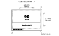
- FIG. 10 is a diagram showing a specific example of a first content screen 31CA included in the content screen 31C.
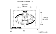
- FIG. 11 is a diagram showing a specific example of a second content screen 31CB (vehicle state display screen) included in the content screen 31C.
- the second content screen 31CB displays optional information that is different from the optional information displayed on the first content screen 31CA.
- the content screen 31C may include multiple screens that display different optional information. Of these multiple screens, the screen that contains the optional information that the occupant wants to check may be alternatively selected, for example, by an in-vehicle switch (not shown), and displayed as the content screen 31C.
- the first content screen 31CA is a screen that displays vehicle speed information and audio information as optional information, and has a first display unit 16, for example, as shown in FIG. 10.
- the first content screen 31CA may have a selection mode display unit 13.
- the first display unit 16 is a portion that displays vehicle speed information and audio information, and for example, the vehicle speed information and audio information are displayed side by side vertically.
- the positions at which the first display unit 16 and the selected mode display unit 13 are provided in the first content screen 31CA are not particularly limited, but since these display units 13 and 16 are simultaneously displayed in the same display screen 31, it is preferable that they do not overlap with each other.
- the first display unit 16 is widely arranged over almost the entire area of the first content screen 31CA, and the selected mode display unit 13 is arranged at the bottom of the first content screen 31CA (below the first display unit 16).
- the second content screen 31CB is a screen that displays the state of yaw control for the vehicle 1 as optional information, and displays the state of the yaw control and the operating state of the transfer device 5 in the selected drive mode as AWC information.
- the second content screen 31CB has a state display section 12 and a yaw state display section 17.
- the second content screen 31CB may also have a selected mode display section 13.
- the yaw state display section 17 is a section that displays the state of yaw control.
- the yaw state display section 17 displays, for example, four gauges that divide an ellipse vertically and horizontally. In the yaw state display section 17, each gauge is turned on or off depending on the direction of the yaw moment controlled by the operation of the yaw control function, and the scale of each gauge expands or contracts depending on the strength of the yaw moment.
- the positions at which the status display unit 12, yaw status display unit 17, and selected mode display unit 13 are provided within the second content screen 31CB are not particularly limited, but since these display units 12, 13, and 17 are displayed simultaneously within the same display screen 31, it is preferable that they do not overlap with each other.
- the status display unit 12 is disposed approximately in the center of the second content screen 31CB
- the yaw status display unit 17 is disposed so as to surround the status display unit 12
- the selected mode display unit 13 is disposed at the very bottom of the second content screen 31CB (below the yaw status display unit 17).
- First route Rt1 When the first switch 2 is operated, a route for switching from the content screen 31C to the first screen 31A at the time of operation.
- Second route Rt2 A route for switching from the first screen 31A to the content screen 31C when the first switch 2 is not operated again after the operation of the first switch 2 and switching of the operating state of the transfer device 5 is completed.
- Third route Rt3 A route for switching from the first screen 31A to the content screen 31C due to the third switch 6 being operated before the display screen 31 is switched on the second route Rt2.
- Route 4 After the content screen 31C is displayed on the third route Rt3, when the switching of the operating state of the transfer device 5 is completed, the content screen 31C is switched to the first screen 31A (the first screen 31A is redisplayed).
- Route 5 After the first screen 31A is redisplayed on the fourth route Rt4, when the first switch 2 is not operated within a predetermined time (e.g., 4 seconds) or when the third switch 6 is operated, the first screen 31A is switched to the content screen 31C.
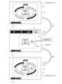
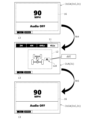
- Figure 12 is a diagram showing the flow of switching from the content screen 31C to the first screen 31A on the first route Rt1, and returning from the first screen 31A to the content screen 31C on the second route Rt2.
- the second content screen 31CB is shown as an example of the content screen 31C, but the type of content screen 31C is not important.
- the display switches from the content screen 31C (top of the figure) to the first screen 31A (center of the figure) (first route Rt1).
- the selected drive mode switches, for example, from 4HLc mode to 4LLc mode. In this way, when the selected drive mode switches, the screen transitions from the content screen 31C to the first screen 31A.
- the drive mode display section 11 and status display section 12 of the first screen 31A (center of the figure) display information related to the drive mode, which can help the occupant understand the drive mode.
- the yaw status display section 17 provided on the second content screen 31CB is not displayed on the first screen 31A (center of the figure). By not displaying the option information, the information related to the drive mode can be displayed more clearly to the occupant.
- the low icon 12d flashes until the operation state of the transfer device 5 is switched over completely, and then lights up after the switching is complete. This allows the occupant to recognize that the operation state of the transfer device 5 is being switched over and that the switching has been completed. Note that if the first switch 2 is operated again after switching to the first screen 31A and before going to the next second route Rt2, the first screen 31A will continue to be displayed.
- the first screen 31A (center in the figure) displayed on the first route Rt1 is switched to the content screen 31C (bottom in the figure) at the completion point, as indicated by the outlined arrow Rt2 in the figure (second route Rt2).
- the screen switching condition on the second route Rt2 is that the switching of the operation state of the transfer device 5 is completed without the first switch 2 being operated again.
- the display screen 31 does not need to be switched at the point of completion of the switching of the operation state of the transfer device 5 (i.e., immediately after the low icon 12d is lit).
- the display screen 31 may be switched when a predetermined time (e.g., 4 seconds) has elapsed after the switching of the operation state of the transfer device 5 is completed. In this way, when there is no switch operation, the display screen 31 returns to the content screen 31C as appropriate, so that optional information that the occupant wants to check can be displayed. This improves the usability of the display device 10.
- a predetermined time e.g. 4 seconds
- the selected driving mode when the selected drive mode is switched, the selected driving mode automatically (without operating the second switch 3) switches to the common drive mode (NORMAL mode).
- NVMAL mode the common drive mode
- the selected driving mode is switched from SAND mode to NORMAL mode when the drive mode is switched (operation of the first switch 2).
- the word "NORMAL" is displayed on the selected mode display section 13 of the first screen 31A (center of the figure), so the occupant can understand the selected driving mode.
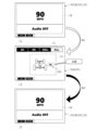
- FIG. 13 is a diagram showing a flow of switching from content screen 31C to first screen 31A on the first route Rt1, and returning from first screen 31A to content screen 31C on the third route Rt3. Note that in FIG. 13, first content screen 31CA is shown as an example of content screen 31C, but the type of content screen 31C is not important.
- the content screen 31C (top of the figure) is switched to the first screen 31A (center of the figure) as shown by the outlined arrow Rt1 in FIG. 13 (first route Rt1).
- the selected drive mode is switched, for example, from 4HLc mode to 4LLc mode.
- the third switch 6 is operated before the switching condition for the second route Rt2 is met (for example, while the low icon 12d is flashing), as shown by the black arrow Rt3 in FIG. 13, the screen is switched from the first screen 31A (center in the figure) to the content screen 31C (bottom in the figure) (third route Rt3).
- the third switch 6 is operated before the switching of the operating state of the transfer device 5 is completed, the screen is forcibly returned to the content screen 31C. This makes it possible to display optional information that the occupant wants to check, making the display device 10 easier to use.
- the third switch 6 is a switch that is operated when the driver has completed selecting the drive mode and no longer needs to look at the first screen 31A (when confirming the drive mode).
- FIG. 14 is a diagram showing the flow of switching from the content screen 31C (bottom of FIG. 13) displayed via the third route Rt3 in FIG. 13 to the first screen 31A via the fourth route Rt4, and then returning from the first screen 31A to the content screen 31C via the fifth route Rt5.
- the content screen 31C (top in FIG. 14), which is switched and displayed via the third route Rt3, is switched to the first screen 31A (center in the figure) as indicated by the solid black arrow Rt4 in the figure when switching of the operating state of the transfer device 5 is complete (fourth route Rt4).
- the first screen 31A it is possible to notify the occupant that the mechanical switching (switching of the driving mode) of the transfer device 5 is complete. It is also possible to make the occupant aware of the operating state of the transfer device 5 after switching. Note that while the first screen 31A is being redisplayed, the switching of the operating state of the transfer device 5 has been completed, and therefore the low icon 12d is displayed as lit.
- the redisplayed first screen 31A (center in the figure) is switched to the content screen 31C (bottom in the figure) as indicated by the black arrow Rt5 in the figure (fifth route Rt5).
- the screen switches to the content screen 31C, making the display device 10 easier to use. Note that if the first switch 2 is operated again within a specified time after the redisplay, the first screen 31A continues to be displayed, and then switches to the content screen 31C via the second route Rt2 or the third route Rt3.
- Sixth route Rt6 A route for switching from the content screen 31C to the second screen 31B at the time of operation of the second switch 3 when the second switch 3 is operated.
- Seventh route Rt7 A route for switching from the second screen 31B to the content screen 31C when the second switch 3 is not operated again within a predetermined time (e.g., 4 seconds) after the operation of the second switch 3.
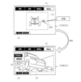
- Figure 15 is a diagram showing the flow of switching from the content screen 31C to the second screen 31B on the sixth route Rt6, and returning from the second screen 31B to the content screen 31C on the seventh route Rt7. Note that Figure 15 shows the first content screen 31CA as an example of the content screen 31C, but the type of content screen 31C is not important.
- the second switch 3 When the second switch 3 is operated by the occupant while the content screen 31C is displayed, as shown by the outlined arrow Rt6 in the figure, the content screen 31C (top of the figure) is switched to the second screen 31B (center of the figure) (sixth route Rt6).
- the selected driving mode is switched, for example, from NORMAL mode to ROCK mode. In this way, when the selected driving mode is switched, the content screen 31C transitions to the second screen 31B.
- the driving mode display section 14 and image display section 15 of the second screen 31B (center of the figure) display information related to the driving mode, which helps the occupant understand the driving mode.
- the second screen 31B is provided with a drive mode display section 11, which allows the occupant to grasp the relationship between the selected drive mode and the drive modes that can be selected for the selected drive mode.
- the second screen 31B (center in the figure) displayed on the sixth route Rt6 is switched to the content screen 31C (bottom in the figure) as indicated by the white arrow Rt7 in the figure (seventh route Rt7) if a predetermined time has passed after the second switch 3 is operated without the second switch 3 being operated again. In this way, if there is no switch operation, the content screen 31C is appropriately returned to, making the display device 10 easier to use. Note that if the second switch 3 is operated again after switching to the second screen 31B before going to the next seventh route Rt7, the second screen 31B will continue to be displayed. Then, if a predetermined time has passed after the second switch 3 is operated again without the second switch 3 being operated again, it will switch to the content screen 31C on the seventh route Rt7.
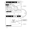
- Fig. 16 is a diagram showing the flow of switching from the first screen 31A to the second screen 31B on the eighth route Rt8.
- Fig. 17 is a diagram showing the flow of switching from the second screen 31B to the first screen 31A on the ninth route Rt9.
- Fig. 16 shows the case where the second switch 3 is operated while the first screen 31A (center in the figure) is displayed, which is switched and displayed on the first route Rt1 in Fig. 12 or Fig. 13.
- Fig. 17 shows the case where the first switch 2 is operated while the second screen 31B (bottom in the figure) is displayed, which is switched and displayed in Fig. 16.
- the display switches from the first screen 31A (top of the figure) to the second screen 31B (bottom of the figure) as shown by the outlined arrow Rt8 in the figure (eighth route Rt8).
- the selected driving mode switches, for example, from NORMAL mode to ROCK mode.
- the display switches from the second screen 31B (top of the figure) to the first screen 31A (bottom of the figure) as indicated by the outlined arrow Rt9 in the figure (ninth route Rt9).
- the selected drive mode switches, for example, from 4LLc mode to 4HLc mode.
- the low icon 12d in the status display section 12 of the first screen 31A flashes until the switching of the operating state of the transfer device 5 is completed, and is then turned off.
- the display screen 31 is appropriately switched in response to the operation of the most recent switches 2 and 3, so that it is possible to visually recognize whether the first switch 2 and the second switch 3 relate to the setting of the drive mode or the traveling mode. This improves the usability of the display device 10.
- the selected driving mode is ROCK mode
- operating the first switch 2 switches the selected driving mode to NORMAL mode.
- the word "NORMAL” is displayed in the selected mode display section 13 on the first screen 31A (bottom of the figure), so the occupant can understand the selected driving mode.
- the display device 10 described above includes a content screen 31C, a first screen 31A, and a second screen 31B.
- the first screen 31A is displayed by switching from the content screen 31C when the occupant operates the first switch 2 while the content screen 31C is being displayed (first route Rt1).
- the second screen 31B is displayed by switching from the content screen 31C when the occupant operates the second switch 3 while the content screen 31C is being displayed (sixth route Rt6).
- the display device 10 appropriately switches between the screens 31A to 31C in response to the operation of the switches 2 and 3, and thus can appropriately display a variety of information including the drive mode and the traveling mode.
- the first screen 31A is provided with a status display section 12. This allows the characteristics of the selected drive mode to be grasped at a glance. This helps the occupant to understand the drive modes. Ultimately, it can encourage the occupant to select a more appropriate drive mode.
- the second screen 31B also has a drive mode display section 11 and a driving mode display section 14. This allows the driver to see at a glance the currently selected driving mode, the selectable driving modes, and the relationship between the currently selected driving mode and the driving modes selectable in this driving mode. This helps the driver understand the driving modes. This in turn encourages the driver to select an appropriate driving mode.
- the display device 10 When the second switch 3 is operated while the first screen 31A is displayed, the display device 10 described above displays the second screen 31B (eighth route Rt8), and when the first switch 2 is operated while the second screen 31B is displayed, the display device 10 displays the first screen 31A (ninth route Rt9). In this way, by switching to screens 31A and 31B that display information related to the mode set by switches 2 and 3 in response to the operation of switches 2 and 3, the display device 10 can prompt the occupant to select an appropriate mode.
- the display device 10 described above displays the content screen 31C if the second switch 3 is not operated again for a predetermined time while the second screen 31B is displayed (seventh route Rt7). Furthermore, the display device 10 displays the content screen 31C if the first switch 2 is not operated again before the operation state of the transfer device 5 is completely switched while the first screen 31A is displayed (second route Rt2). In this way, when the switches 2 and 3 are not operated, the display device 10 can return to the content screen 31C as appropriate, thereby displaying the information that the occupant wants to check. This makes it possible to improve the convenience of the display device 10.
- the display device 10 displays the content screen 31C (third route Rt3). In this way, by forcibly returning to the content screen 31C in response to the operation of the third switch 6, it is possible to display the information that the occupant wants to confirm. Therefore, even when it takes time to switch the operating state of the transfer device 5, for example, while the vehicle 1 is stopped, it is possible to display the information that the occupant wants to confirm. In other words, when the display device 10 determines that the selection of the drive mode has been confirmed by the occupant operating the third switch 6, it determines that there is no need to display the first screen 31A, and displays the content screen 31C. This makes it possible to display the information that the occupant wants to confirm, thereby improving the convenience of the display device 10.
- the display device 10 described above displays the content screen 31C in response to the operation of the third switch 6, it redisplays the first screen 31A when the switching of the operating state of the transfer device 5 is complete (fourth route Rt4). Furthermore, if the first switch 2 is not operated within a predetermined time after the redisplay, or if the third switch 6 is operated, it displays the content screen 31C (fifth route Rt5). In this way, it is possible to notify the completion of switching of the operating information of the transfer device 5. Furthermore, by appropriately returning to the content screen 31C, it is possible to increase the convenience of the display device 10.
- the icons 12a to 12d are displayed either lit or unlit depending on the selected drive mode. Furthermore, while the operating state of the transfer device 5 is being switched, the icons 12a to 12d, whose display state changes before and after the switch, are displayed flashing. This allows the occupant to recognize that the operating state of the transfer device 5 is being mechanically switched and that the switch has been completed. Furthermore, the sense of controlling the transfer device 5 through the operation of the first switch 2 is further enhanced.
- the display device 10 described above switches to display the first screen 31A (ninth route Rt9).
- the NORMAL mode which is a common driving mode
- the selected driving mode is displayed in the selected mode display section 13 of the first screen 31A.
- the common driving mode is commonly selected, and the selected driving mode can be visually confirmed on the first screen 31A, so that it is possible to prevent the occupant from becoming unaware of the selected driving mode.
- the second content screen 31CB has a status display section 12 and a yaw status display section 17.
- the status display section 12 and the yaw status display section 17 are simultaneously displayed on the same screen, allowing the occupant to understand the status of the vehicle 1.
- the yaw status display section 17 is not displayed on the first screen 31A, information related to the drive mode can be displayed in a more easily understandable manner.
- the above-described display device 10 is merely an example, and is not limited to the above. Furthermore, the vehicle 1 to which the above-described display device 10 is applied is also merely an example, and is not limited to the above.
- the drive modes need to have at least two or more modes corresponding to the operating state of the transfer device 5, and are not limited to the four modes of 2H mode, 4H mode, 4HLc mode, and 4LLc mode. For example, a mode different from the above four modes may be provided. Also, depending on the configuration of the transfer device 5, at least one of the above four modes may be omitted. For example, if the transfer device 5 does not have a switching mechanism 5B, the 2H mode may be omitted. Also, if the transfer device 5 does not have a sub-reduction mechanism 5D, the 4LLc mode may be omitted.
- the driving modes need only have at least two or more modes for implementing control according to the driving environment, and are not limited to the seven driving modes described above.
- the driving modes may have a driving mode different from the seven driving modes described above.
- at least one of the seven driving modes described above may be omitted.
- the driving modes do not need to have a common mode, and even if a common mode is provided, it does not need to be a NORMAL mode.
- the driving modes that can be selected in each drive mode are not limited to the example in the table of FIG. 3.
- At least the first route Rt1 and the sixth route Rt6 may be provided for switching the display screen 31.
- a route may be provided for switching from the first screen 31A to the content screen 31C if the first switch 2 is not operated again within a predetermined time (e.g., 4 seconds) after the first switch 2 is operated.
- a route may be provided for switching from the second screen 31B to the content screen 31C when the third switch 6 is operated before the display screen 31 is switched on the seventh route Rt7.
- the first screen 31A may have at least the status display section 12, and the drive mode display section 11 and the selected mode display section 13 may be omitted.
- the first screen 31A may also have other display sections.
- the second screen 31B may have at least the drive mode display section 11 and the driving mode display section 14, and the image display section 15 and the selected mode display section 13 may be omitted.
- the second screen 31B may have other display sections.
- the content screen 31C may include screens other than the first content screen 31CA and the second content screen 31CB.
- the driving mode display unit 11 only needs to display at least the selected driving mode in a recognizable manner, and the selected driving mode does not need to be highlighted.
- the driving mode display unit 14 only needs to display at least the selected driving mode in a recognizable manner, and the selected driving mode does not need to be highlighted.
- the driving mode display unit 14 may display the selected driving mode in a recognizable manner by displaying multiple selectable driving modes side-by-side, with the selected driving mode always at the front (top).
- the placement of the switches 2, 3, and 6 is not limited to the above positions, but may be any position that allows an occupant (mainly the driver) to operate them.
- the first switch 2 does not have to be a rotary switch, and the second switch 3 does not have to be a push switch.
- the second switch 3 may be, for example, a toggle switch with an operating lever that can be tilted forwards or backwards.
- the third switch 6 may be omitted.
- This invention can be used in the manufacturing industry of display devices mounted on vehicles, and also in the manufacturing industry of vehicles equipped with such display devices.
Landscapes
- Engineering & Computer Science (AREA)
- Chemical & Material Sciences (AREA)
- Combustion & Propulsion (AREA)
- Transportation (AREA)
- Mechanical Engineering (AREA)
- Arrangement And Driving Of Transmission Devices (AREA)
Abstract
複数の駆動モードを切り替えて一つを選択する第一スイッチ(2)と、複数の走行モードを切り替えて一つを選択する第二スイッチ(3)と、を具備した車両に搭載される表示装置(10)は、車両に関するコンテンツ情報を表示するコンテンツ画面と、第一スイッチ(2)が操作されることでコンテンツ画面から切り替えられて表示される第一画面と、第二スイッチ(3)が操作されることでコンテンツ画面から切り替えられて表示される第二画面と、を備える。第一画面は、選択中の駆動モードにおけるトランスファ装置の作動状態を表示する状態表示部を有する。第二画面は、複数の駆動モードを並べて表示するとともに選択中の駆動モードを認識可能に表示する駆動モード表示部と、選択中の駆動モードで選択可能な前記走行モードを並べて表示するとともに選択中の走行モードを認識可能に表示する走行モード表示部と、を有する。
Description
本件は、車両の駆動モード及び走行モードに係る情報を表示する表示装置に関する。
従来、前輪及び後輪の駆動状態を変更するトランスファ装置を具備した車両に適用されて、駆動モード及び走行モードに係る情報を表示する表示装置が知られている。ここで、駆動モードとは、トランスファ装置の状態に応じて設定されるモードを意味する。また、走行モードとは、車両の走行状況に応じて設定される制御上のモードを意味する。例えば、特許文献1には、複数の駆動モードのうち選択中の駆動モードと複数の走行モードのうち選択中の走行モードとを同一画面に表示させる表示装置(表示制御部)が開示されている。
特許文献1は、オフロードでの走行モードを適切に設定できるようにした技術であり、選択中の駆動モード及び選択中の走行モードのみがシンプルに表示される。しかし、近年の表示装置では、駆動モードや走行モードに係る情報だけでなく多様な情報が表示されることがある。このような多様な情報が表示されることで表示装置の利便性が向上し得る。一方で、各モードの選択時には、選択されるモードに係る情報が表示されることが望ましい。これにより、選択されたモードに対する乗員の理解を援ける効果が期待できるとともに、より最適なモード選択を乗員に対して促す効果が期待できる。つまり、特許文献1に開示の装置では、駆動モード及び走行モードを含む多様な情報を適切に表示するうえで改善の余地がある。
本件は、このような課題に鑑み創案されたものであり、駆動モード及び走行モードに係る情報を含む多様な情報を適切に表示することを目的の一つとする。なお、この目的に限らず、後述する「発明を実施するための形態」に示す各構成から導き出される作用効果であって、従来の技術では得られない作用効果を奏することも、本件の他の目的である。
開示の表示装置は、以下に開示する態様(適用例)として実現でき、上記の課題の少なくとも一部を解決する。態様2以降の各態様は、何れもが付加的に適宜選択されうる態様であって、何れもが省略可能な態様である。態様2以降の各態様は、何れもが本件にとって必要不可欠な態様や構成を開示するものではない。
態様1.開示する表示装置は、前輪及び後輪の駆動状態を変更するトランスファ装置と、前記トランスファ装置の作動状態に応じた複数の駆動モードを切り替えて一つを選択する第一スイッチと、走行環境に応じた制御を実施する複数の走行モードを切り替えて一つを選択する第二スイッチと、を具備した車両に搭載される表示装置であって、前記車両に関するコンテンツ情報を表示するコンテンツ画面と、前記コンテンツ画面の表示中に、乗員により前記第一スイッチが操作されることで前記コンテンツ画面から切り替えられて表示される第一画面と、前記コンテンツ画面の表示中に、前記乗員により前記第二スイッチが操作されることで前記コンテンツ画面から切り替えられて表示される第二画面と、を備える。前記第一画面は、前記複数の駆動モードのうち選択中の駆動モードにおける前記トランスファ装置の作動状態を表示する状態表示部を有する。前記第二画面は、前記複数の駆動モードを並べて表示するとともに前記選択中の駆動モードを認識可能に表示する駆動モード表示部と、前記選択中の駆動モードで選択可能な前記走行モードを並べて表示するとともに選択中の走行モードを認識可能に表示する走行モード表示部と、を有する。
態様2.上記の態様1において、表示装置は、前記第一画面の表示中に、前記第二スイッチが操作された場合には前記第二画面を表示し、前記第二画面の表示中に、前記第一スイッチが操作された場合には前記第一画面を表示することが好ましい。
態様3.上記の態様1又は2において、前記車両には、前記乗員によって操作される第三スイッチが設けられることが好ましい。この場合、表示装置は、前記第二画面の表示中に、前記第二スイッチの操作後の所定時間内に前記第二スイッチが再操作されなかった場合には前記コンテンツ画面を表示し、前記第一画面の表示中に、前記第一スイッチの操作後に前記第一スイッチが再操作されずに前記トランスファ装置の作動状態の切り替えが完了した場合、又は、前記第三スイッチが操作された場合に、前記コンテンツ画面を表示することが好ましい。
態様4.上記の態様3において、表示装置は、前記第三スイッチの操作に伴い前記コンテンツ画面を表示した場合に、前記トランスファ装置の作動状態の切り替えが完了したら、前記第一画面を再表示し、当該再表示後の前記所定時間内に前記第一スイッチが操作されなかった場合、又は、前記第三スイッチが操作された場合に、前記コンテンツ画面を表示することが好ましい。
態様5.上記の態様1~4の何れかにおいて、前記状態表示部には、前記選択中の駆動モードに応じて、前記前輪及び前記後輪を含む部品を示すアイコンが点灯表示又は消灯表示されることが好ましい。この場合、前記選択中の駆動モードが切り替えられた場合には、切り替え前後で表示状態が変化する前記アイコンが、前記トランスファ装置の作動状態の切り替え完了まで点滅し、前記切り替え完了後に点灯表示又は消灯表示されることが好ましい。
態様6.上記の態様2を含む態様において、前記第一画面は、前記選択中の走行モードを表示する選択中モード表示部を有することが好ましい。この場合、前記複数の走行モードには、前記選択中の駆動モードに依らずに選択可能な共通走行モードが設けられており、前記第二画面の表示中に、前記第一スイッチが操作された場合には前記第一画面を表示しつつ、前記選択中の走行モードとして前記共通走行モードが選択されることが好ましい。
態様7.上記の態様1~6の何れかにおいて、前記コンテンツ画面には、前記状態表示部と前記車両に対するヨー制御の状態を表示するヨー状態表示部とを有する車両状態表示画面が含まれることが好ましい。この場合、前記第一画面では、前記ヨー状態表示部が非表示であることが好ましい。
開示の表示装置によれば、駆動モード及び走行モードに係る情報を含む多様な情報を適切に表示することができる。
図面を参照して、実施例形態としての表示装置について説明する。以下に示す実施形態はあくまでも例示に過ぎず、以下の実施形態で明示しない種々の変形や技術の適用を排除する意図はない。各実施形態の構成は、それらの趣旨を逸脱しない範囲で種々変形して実施することができる。また、必要に応じて取捨選択することができ、あるいは適宜組み合わせることができる。
以下の説明では、車両の前進方向を前方(車両前方)とし、この反対方向を後方(車両後方)とする。また、車両の前方を向いた状態を基準にして左右を定める。なお、左右方向は車両前後方向と直交する。以下、左右方向を「車幅方向」ともいい、車両前後方向を単に「前後方向」という。車幅方向及び前後方向の双方に直交する方向を上下方向と定義する。図面において、FRは前、RRは後ろ、RHは右、LHは左、UPは上、DWは下を表す。
[1.構成]
はじめに、図1~図3を参照して、本実施形態の表示装置10が適用される車両1の構成の一例を説明する。その後、本実施形態の表示装置10について詳述する。
はじめに、図1~図3を参照して、本実施形態の表示装置10が適用される車両1の構成の一例を説明する。その後、本実施形態の表示装置10について詳述する。
[1-1.車両構成]
図1は、実施例としての車両1が備える駆動系の装置(パワートレイン)を示す模式図である。車両1は、前輪FW及び後輪RWの駆動状態を変更可能である。車両1には、駆動源4、及び、駆動源4と前後車輪FW,RWとの動力伝達経路上に介装されたトランスファ装置5が設けられる。
図1は、実施例としての車両1が備える駆動系の装置(パワートレイン)を示す模式図である。車両1は、前輪FW及び後輪RWの駆動状態を変更可能である。車両1には、駆動源4、及び、駆動源4と前後車輪FW,RWとの動力伝達経路上に介装されたトランスファ装置5が設けられる。
図1に示すように、車両1には、駆動源4の出力軸に接続されて、ドライバによるシフト操作に応じて変速比が設定される変速機AT(自動変速機)が設けられてよい。また、車両1には、左右の前輪FWの回転差を吸収するとともに、トランスファ装置5から伝達された駆動力を左右の前輪FWに分配,伝達するフロントデファレンシャルFDが設けられてよい。さらに、車両1には、左右の後輪RWの回転差を吸収するとともに、トランスファ装置5から伝達された駆動力を左右の後輪RWに分配,伝達するリアデファレンシャルRDが設けられてよい。なお、変速機AT,フロントデファレンシャルFD,リアデファレンシャルRDは必須ではない。
駆動源4は、例えば、ガソリンや軽油を燃料とする内燃機関(例えばガソリンエンジン,ディーゼルエンジンなど)である。駆動源4は、電動機としての機能と発電機としての機能とを兼ね備えた電動発電機(モータ・ジェネレータ)であってもよい。或いは、車両1は、駆動源4として、内燃機関と電動発電機との双方を備えたハイブリッド自動車(ハイブリッド電気自動車,HEV,Hybrid Electric Vehicle)またはプラグインハイブリッド自動車(プラグインハイブリッド電気自動車,PHEV,Plug-in Hybrid Electric Vehicle)であってもよい。プラグインハイブリッド自動車とは、バッテリに対する外部充電またはバッテリからの外部給電が可能なハイブリッド自動車を意味する。プラグインハイブリッド自動車には、外部充電設備からの電力が送給される充電ケーブルを差し込むための充電口(インレット)や外部給電用のコンセント(アウトレット)が設けられる。
トランスファ装置5は、前輪FW及び後輪RWの駆動状態を変更(又は維持)する装置であり、センターデファレンシャル5A(以下、「センターデフ5A」とよぶ)と切替機構5Bとを備える。本実施例のトランスファ装置5は、さらに、センターデフ5Aの差動をロックするロック機構5Cとセンターデフ5Aに入力される駆動力を変更する副変速機構5Dとを備える。
センターデフ5Aは、前輪FW及び後輪RWの回転差を吸収するとともに駆動力を分配,伝達するものである。センターデフ5Aは、例えば、遊星歯車機構で構成される。切替機構5Bは、センターデフ5Aと前輪FWとの接続状態を切り替えるものである。切替機構5Bは、例えば、センターデフ5Aに連結された複数のクラッチギヤとカップリングスリーブとから構成される。
トランスファ装置5では、切替機構5Bにより、センターデフ5Aと前輪FWとの接続が切り離されることで、後輪RWのみが駆動輪として駆動される二輪駆動状態(2H状態)が実現される。また、切替機構5Bにより、センターデフ5Aと前輪FWとが接続されることで、前輪FWと後輪RWとの回転差を吸収しつつ、前輪FW及び後輪RWの双方が駆動輪として駆動される四輪駆動状態(4H状態)が実現される。
ロック機構5Cは、切替機構5Bによりセンターデフ5Aと前輪FWとが接続されているときに、センターデフ5Aの差動をロックするものである。ロック機構5Cは、例えば、センターデフ5Aに連結された複数のクラッチギヤとカップリングスリーブとから構成される。副変速機構5Dは、ロック機構5Cによりセンターデフ5Aの差動がロックされているときに、センターデフ5Aに入力される駆動力を変更(回転を変速)するハイロー切替機構である。副変速機構5Dは、例えば、複数のギヤとカウンタシャフトとカップリングスリーブとから構成される。副変速機構5Dは、ハイギヤ位置とローギヤ位置とを有し、副変速機構5Dを構成する要素の噛み合いが変更されることで、ハイギヤ位置とローギヤ位置とが切り替えられる。
トランスファ装置5では、ロック機構5Cによりセンターデフ5Aの差動がロックされ、副変速機構5Dがハイギヤ位置とされることで、4H状態とは別の四輪駆動状態(4HLc状態)が実現される。4HLc状態では、副変速機構5Dに入力された回転がセンターデフ5Aに直接的に伝達される。さらに、センターデフ5Aに伝達された回転(駆動力)が差動されることなく、前輪FW及び後輪RWに等配分されて、前輪FW及び後輪RWの双方が駆動輪として駆動される。
また、トランスファ装置5では、ロック機構5Cによりセンターデフ5Aの差動がロックされ、副変速機構5Dがローギヤ位置とされることで、4H状態及び4HLc状態とは別の四輪駆動状態(4LLc状態)が実現される。4LLc状態では、4HLc状態とは異なり、副変速機構5Dに入力された回転が減速されてセンターデフ5Aに伝達される。さらに、センターデフ5Aに伝達された回転(駆動力)が差動されることなく、前輪FW及び後輪RWに等配分されて、前輪FW及び後輪RWの双方が駆動輪として駆動される。
車両1には、上述のトランスファ装置5の作動状態(すなわち、トランスファ装置5が実現する駆動状態)に応じた複数の駆動モードが設けられるとともに、図2に示すように、複数の駆動モードを切り替えて一つを選択する第一スイッチ2が設けられる。さらに、車両1には、第二スイッチ3と第三スイッチ6とが設けられる。第二スイッチ3は、駆動モードとは別の走行モードを設定するためのスイッチである。走行モードについては後述する。各スイッチ2,3,6は、いずれも、乗員(主に、ドライバ)によって操作される物理スイッチである。
駆動モードには、上述のトランスファ装置5の作動状態に対応して、2Hモード,4Hモード,4HLcモード及び4LLcモードの四つが設けられる。2Hモードでは、トランスファ装置5が2H状態を実現し、4Hモードでは、トランスファ装置5が4H状態を実現する。また、4HLcモードでは、トランスファ装置5が4HLc状態を実現し、4LLcモードでは、トランスファ装置5が4LLc状態を実現する。
第一スイッチ2は、これら四つの駆動モードを切り替えて、一つの駆動モードを選択する駆動モードスイッチである。本実施形態において、第一スイッチ2は、センターコンソール1Cの上面に配置されたロータリスイッチとされる。センターコンソール1Cは、運転席1Aと助手席1Bとの間で前後方向且つ車幅方向に沿って展開されたパネルである。
第一スイッチ2には、図2に示すように、円盤部2Aと枠部2Bとが設けられる。円盤部2Aは、センターコンソール1Cに固定されて、センターコンソール1Cの上面と同じ方向(すなわち、上方)を向く円形の端面を持つ円筒状又は円柱状の部材である。円盤部2Aの端面には、各駆動モードを示す語句が表記されている。ここでは、2Hモードを示す「2H」,4Hモードを示す「4H」,4HLcモードを示す「4HLc」及び4LLcモードを示す「4LLc」の語句が、円盤部2Aにおける前側部分において、周方向の左からこの順に表記されている。
枠部2Bは、円盤部2Aの外周面を囲う円筒状の部材であり、図2に破線矢印で示すように、円盤部2Aに対して左回り又は右回りに回転操作可能に構成される。枠部2Bの周方向の一箇所には目盛が刻まれている。第一スイッチ2は、乗員により、枠部2Bが左回り又は右回りに回動されて、枠部2Bの目盛が円盤部2Aに表記されたいずれか一つの語句を指すように操作される。これにより、四つの駆動モードのうちの一つが「選択中の駆動モード」として択一的に選択される。
車両1には、上記の駆動モードとは別であって、車両1の走行環境に応じた制御を実施する複数の走行モードが設けられる。本実施例の走行モードには、NORMALモード,ECOモード,GRAVELモード,SNOWモード,MUDモード,SANDモード及びROCKモードの七つが設けられている。
NORMALモードは、予め設定された標準的な制御が実施されるモードである。ECOモードは、NORMALモードよりも燃費や電費を重視した制御(エコな走り)が実施されるモードである。GRAVELモードは、砂利道での走行に適した制御が実施されるモードである。SNOWモードは、雪道での走行に適した制御が実施されるモードであり、MUDモードは、泥道での走行に適した制御が実施されるモードである。SANDモードは、砂地での走行に適した制御が実施されるモードであり、ROCKモードは、岩道での走行に適した制御が実施されるモードである。
走行モードは、選択中の駆動モードごとに、これら七つの走行モードのうち二つ以上の走行モードが択一的に選択可能となるように設定されており、選択可能な複数の走行モードの一つが「選択中の走行モード」として選択される。
具体的には、図3の表に示すように、選択中の駆動モードが2Hモードである場合には、NORMALモードとECOモードとの二つのうちのどちらか一つが選択可能とされる。また、4Hモードでは、NORMALモードとGRAVELモードとSNOWモードとの三つのうちのいずれか一つが選択可能とされる。4HLcモードでは、NORMALモードとMUDモードとSANDモードの三つのうちのいずれか一つが選択可能とされる。4LLcモードでは、NORMALモードとROCKモードとの二つのうちのどちらか一つが選択可能とされる。なお、本実施例において、NORMALモードは、どの駆動モードでも選択可能な共通走行モードとして設定されている。
このように駆動モードごとに選択可能な走行モードが設定されることで、トランスファ装置5の作動状態に適した走行を実現することができる。車両1では、選択中の走行モードに応じて車載装置(例えば、駆動源4や変速機AT,或いは図示しない制動装置)が適宜制御される。
第二スイッチ3は、選択中の駆動モードで選択可能な複数の走行モードを切り替えて、一つの走行モードを選択する走行モードスイッチである。第二スイッチ3は、図2に示すように、例えば、センターコンソール1Cの上面に配置されたプッシュスイッチとされる。第二スイッチ3には、下方向に押圧操作可能なプッシュボタン3Aが設けられる。第二スイッチ3は、乗員により当該プッシュボタン3Aが下方向に押圧操作されることで、選択中の走行モードが切り替えられる。なお、プッシュボタン3Aは、押圧操作後にもとの位置に復帰する。つまり、走行操作スイッチ3は、モーメンタリ式のプッシュスイッチである。
選択中の走行モードの切り替えは、例えば、図3の表の上下方向に対応して実施される。例えば、選択中の駆動モードが「4Hモード」であり、選択中の走行モードが「GRAVELモード」である場合に、プッシュボタン3Aが押圧操作されると、選択中の走行モードが、「GRAVELモード」からその下段の「SNOWモード」に切り替わる。また、選択中の走行モードが「SNOWモード」である場合に、プッシュボタン3Aが押圧操作されると、選択中の走行モードは、「4Hモード」の列の最も上段の「NORMALモード」に切り替わる。
なお、本実施例では、選択中の駆動モードが切り替わった場合に、選択中の走行モードとして、共通走行モードであるNORMALモードが選択される。つまり、切り替え前の駆動モードで選択されていた走行モードが、駆動モードの切り替えに伴って共通走行モードに切り替えられる。このように、本実施例では、選択中の走行モードが、第二スイッチ3が操作されていない場合にも(すなわち自動的に)切り替えられ得る。選択中の駆動モードが切り替わった場合に、選択中の走行モードが自動的に共通走行モードに切り替えられることで、駆動モードの切り替え後における選択中の走行モードが、どの走行モードであるかを乗員が理解しやすくなる。
第三スイッチ6は、後述する第一画面31Aから後述するコンテンツ画面31Cに切り替えるためのスイッチである。第三スイッチ6は、図2に示すように、例えば、ハンドル1Hに配置されたモーメンタリ式のプッシュスイッチとされる。
[1-2.表示装置]
図4は、実施形態としての表示装置10の構成を示すブロック図である。この表示装置10は、上記の駆動モード及び走行モードに係る情報を含む車両1に関する情報(以下、「コンテンツ情報」ともよぶ)を表示する装置であり、少なくとも各スイッチ2,3の操作に伴って、画面を適宜切り替えて表示するものである。
図4は、実施形態としての表示装置10の構成を示すブロック図である。この表示装置10は、上記の駆動モード及び走行モードに係る情報を含む車両1に関する情報(以下、「コンテンツ情報」ともよぶ)を表示する装置であり、少なくとも各スイッチ2,3の操作に伴って、画面を適宜切り替えて表示するものである。
表示装置10は、このように、スイッチ操作に伴い画面を切り替えることで、多様な情報を確認したいという要求に応えつつ、駆動モード及び走行モードのそれぞれについての乗員の理解を援ける機能を持つ。図4に示すように、表示装置10の入力側には、第一スイッチ2及び第二スイッチ3が接続される。また、表示装置10の入力側には、第三スイッチ6が接続されてよい。表示装置10には、これらのスイッチ2,3,6の操作情報が随時伝達される。
コンテンツ情報には、駆動モード及び走行モードに係る情報の他に、車両1の車速情報が含まれてよい。また、コンテンツ情報には、ヨー制御〔アクティブヨーコントロール(AYC)〕に係る情報が含まれていてもよい。
これに加えて、コンテンツ情報には、車両1の走行状態に係る情報が含まれてよい。車両1の走行状態に係るコンテンツ情報の具体例としては、シフトポジション,変速機ATの減速比,走行距離,推定走行可能距離,燃費,電費,バッテリ残容量,ロールレート,ピッチレート,前後加速度,横加速度,路面傾斜角度,タイヤ空気圧,走行方向(方位),標高,気温,路面摩擦係数といった情報が挙げられる。
さらに、コンテンツ情報には、車載機器の作動状態に係る情報が含まれてよい。車載機器の作動状態を表すコンテンツ情報には、オーディオ情報,カーナビゲーション情報,照明状態情報,クルーズコントロール関連情報,車間距離情報,各種ウェブサイトなどが挙げられる。また、表示装置10は、乗員(ユーザ)のスマートフォンと接続され、スマートフォンの作動状態を表すコンテンツ情報(例えば、通話情報やメールの送受信情報など)を表示してもよい。
駆動モードに係る情報は、例えば、第一スイッチ2で生成又は取得され、表示装置10に伝達される。或いは、当該情報は、第一スイッチ2の操作情報を基に図示しないECUで生成又は取得され、表示装置10に伝達されてもよい。同様に、走行モードに係る情報は、例えば、第二スイッチ3で生成又は取得され、表示装置10に伝達される。或いは、当該情報は、第二スイッチ3の操作情報を基に図示しないECUで生成又は取得され、表示装置10に伝達されてもよい。その他の情報は、例えば、各種ECU,各種車載機器,各種センサなど(いずれも図示せず)で生成又は取得され、表示装置10に伝達される。
表示装置10は電子制御装置20と出力装置30とを備える。電子制御装置20は、出力装置30に表示される内容を制御するためのコンピュータであり、プロセッサ(演算処理装置)及びメモリ(記憶装置)を内蔵する。電子制御装置20の処理内容(プログラム)はメモリに保存され、その内容がプロセッサに適宜読み込まれることによって実行される。なお、電子制御装置20は、出力装置30と一体に形成(出力装置30に内蔵)されていてもよいし、出力装置30とは別体に設けられていてもよい。
出力装置30は、車両1に関する情報を表示する装置であり、例えば液晶ディスプレイや有機EL(Electro-Luminescence)ディスプレイやプロジェクタなどである。以下、情報が表示されるディスプレイやプロジェクタスクリーンのことを表示画面31(画面,図5など参照)ともよぶ。表示画面31に表示されるすべての情報は、電子制御装置20によって制御される。
表示画面31の形状(情報が表示される領域の形状)は特に限定されないが、例えば矩形形状である。本実施形態の表示画面31の形状は、図2に示すように、上下方向に沿う短辺と左右方向に沿う長辺とを有する矩形形状とされる。以下、表示画面31の短辺が延びる方向を縦方向ともよび、長辺が延びる方向を横方向ともよぶ。出力装置30が配置される位置は、特に限定されないが、好ましくはドライバが見やすい位置に配置される。本実施形態において、出力装置30(表示画面31)は、ドライバの前方(ハンドル1Hの前方)に配置される。
[2.表示形式の詳細]
表示装置10は、出力装置30に表示される情報の表示形式として、三種類の表示形式(第一表示形式10A,第二表示形式10B,主表示形式10C)を備える。第一表示形式10Aは、第一スイッチ2が操作された場合に、駆動モードに係る情報を表示する形式である。第二表示形式10Bは、第二スイッチ3が操作された場合に、走行モードに係る情報を表示する形式である。主表示形式10Cは、上記二つの場合以外の場合に、コンテンツ情報を表示する形式である。これらの表示形式10A~10Cの切り替わりについては後述する。
表示装置10は、出力装置30に表示される情報の表示形式として、三種類の表示形式(第一表示形式10A,第二表示形式10B,主表示形式10C)を備える。第一表示形式10Aは、第一スイッチ2が操作された場合に、駆動モードに係る情報を表示する形式である。第二表示形式10Bは、第二スイッチ3が操作された場合に、走行モードに係る情報を表示する形式である。主表示形式10Cは、上記二つの場合以外の場合に、コンテンツ情報を表示する形式である。これらの表示形式10A~10Cの切り替わりについては後述する。
[2-1.第一表示形式]
第一表示形式10Aは、上述の通り、駆動モードに係る情報を表示する形式であり、図5及び図6に具体例で示すように、第一画面31Aを有する。図5は、選択中の駆動モードが4LLcモードである場合を示す。また、図6は、図5の状態で第一スイッチ2が操作されたことで、選択中の駆動モードが4LLcモードから4HLcモードに切り替わった場合を示す。
第一表示形式10Aは、上述の通り、駆動モードに係る情報を表示する形式であり、図5及び図6に具体例で示すように、第一画面31Aを有する。図5は、選択中の駆動モードが4LLcモードである場合を示す。また、図6は、図5の状態で第一スイッチ2が操作されたことで、選択中の駆動モードが4LLcモードから4HLcモードに切り替わった場合を示す。
図5及び図6に示すように、第一画面31Aは、状態表示部12を有する。本実施形態の第一画面31Aは、さらに、駆動モード表示部11と選択中モード表示部13とを有する。状態表示部12は、複数の駆動モードのうち選択中の駆動モードにおけるトランスファ装置5の作動状態を表示する部位である。駆動モード表示部11は、複数の駆動モードを並べて表示するとともに、選択中の駆動モードを認識可能に表示する部位である。選択中モード表示部13は、選択中の走行モードを表示する部位である。
このように、駆動モードに係る情報を表示する部位として、状態表示部12が設けられることで、選択中の駆動モードの特性を把握することができる。よって、駆動モードに対する乗員の理解を援けることができる。さらに、本実施形態では、駆動モードに係る情報を表示する部位として、駆動モード表示部11が設けられることで、選択中の駆動モードだけでなく、選択可能な駆動モードを、乗員がひと目で把握することができる。よって、駆動モードに対する乗員の理解をさらに援けることができる。また、選択中モード表示部13に選択中の走行モードが表示されることで、選択中の走行モードについても把握することができる。
詳述すると、駆動モード表示部11には、例えば、複数の駆動モードが、第一スイッチ2の操作方向に対応する方向(すなわち、横方向)に並べて配置される。上述のとおり、本実施形態では、2Hモード,4Hモード,4HLcモード及び4LLcモードの四つの駆動モードが設けられている。また、第一スイッチ2では、図2に示すように、周方向の左から「2H」,「4H」,「4HLc」及び「4LLc」の順に各駆動モードを示す語句が表記される。これに対応して、駆動モード表示部11には、各駆動モードを示す「2H」,「4H」,「4HLc」及び「4LLc」の語句が左からこの順で表示される。このように、駆動モード表示部11に表示される各駆動モードの並び順と、第一スイッチ2で選択される各駆動モードの並び順とが互いに対応(一致)しているので、選択中の駆動モードを切り替えたい場合に、第一スイッチ2を操作する方向が直感的に理解しやすくなる。
さらに、図5に示すように、駆動モード表示部11には、選択中の駆動モード(ここでは、4LLcモード)を示すタブが、他の駆動モードを示すタブと異なる色で強調表示されることで、選択中の駆動モードが認識可能に表示される。また、図6に示すように、第一スイッチ2の左方向への操作に伴って、選択中の駆動モードが4LLcモードから4HLcモードに切り替えられると、選択中の駆動モードが左方向へ切り替え表示される。つまり、4LLcモードを示すタブの左隣りに位置する4HLcモードを示すタブが、他の駆動モードとは異なる色で強調表示されるように切り替わる。駆動モード表示部11では、このように選択中の駆動モードが強調表示されるので、選択中の駆動モードを一目で把握することができる。
図7(a)~(d)は、状態表示部12の具体例を示す図である。なお、図7(a)~(d)はそれぞれ、選択中の駆動モードが、2Hモード,4Hモード,4HLcモード,4LLcモードである場合を示す。図7(a)~(d)に示すように、状態表示部12には、車両1のパワートレインを模した画像が表示される。当該画像には、パワートレインに含まれる部品を示すアイコン12a~12dが含まれる。ここでは、前輪FWを模した前輪アイコン12a,後輪RWを模した後輪アイコン12b及びトランスファ装置5(ロック機構5C)を模したロックアイコン12cを例示する。状態表示部12には、副変速機構5Dがローギヤ位置であることを示すローアイコン12d〔図7(d)参照〕が含まれてもよい。
状態表示部12では、これらのアイコン12a~12dが、選択中の駆動モードに応じて点灯表示又は消灯表示される。なお、図7(a)~(d)において、白塗りのアイコンは、当該アイコンが点灯表示されていることを示し、黒塗りのアイコンは、当該アイコンが消灯表示されていることを示す。ローアイコン12dは、消灯表示時には表示されない(非表示となる)。
例えば、選択中の駆動モードが2Hモードである場合には、図7(a)に示すように、後輪アイコン12bが点灯表示され、その他のアイコン12a,12c,12dが消灯表示される。これにより、トランスファ装置5の作動状態が、後輪RWのみが駆動輪となる2H状態であることが表現される。また、選択中の駆動モードが4Hモードである場合には、図7(b)に示すように、前輪アイコン12a及び後輪アイコン12bが点灯表示され、その他のアイコン12c,12dが消灯表示される。これにより、トランスファ装置5の作動状態が、前輪FW及び後輪RWの双方が駆動輪となる4H状態であることが表現される。
選択中の駆動モードが4HLcモードである場合には、図7(c)に示すように、前輪アイコン12a,後輪アイコン12b及びロックアイコン12cが点灯表示され、ローアイコン12dが消灯表示される。これにより、トランスファ装置5の作動状態が、四輪駆動状態のうちセンターデフ5Aの差動がロックされる4HLc状態であることが表現される。選択中の駆動モードが4LLcモードである場合には、図7(d)に示すように、全てのアイコン12a~12dが点灯表示される。これにより、トランスファ装置5の作動状態が、四輪駆動状態のうちセンターデフ5Aの差動がロックされ、且つ、副変速機構5Dがローギヤ位置とされる4LLc状態であることが表現される。
また、状態表示部12では、トランスファ装置5の作動状態の切り替え中に、切り替え前後で表示状態が変化するアイコン12a~12dが、トランスファ装置5の作動状態の切り替え完了まで点滅表示される。上述の通り、トランスファ装置5は、各機構5B~5Dの状態が機械的に切り替わることで、その作動状態が切り替わる。このため、トランスファ装置5の作動状態の切り替え中にアイコン12a~12dを点滅表示させることで、選択中の駆動モードの切り替え中であることを乗員に報知できる。また、トランスファ装置5の作動状態に応じて、このように表示が変化することで、第一スイッチ2の操作を介して、トランスファ装置5を制御(操作)している感覚を、乗員に持たせることができる。
例えば、選択中の駆動モードが2Hモードから4Hモードに切り替えられた場合について説明する。この場合、消灯表示されていた前輪アイコン12a〔図7(a)参照〕が、トランスファ装置5の作動状態の切り替えが完了するまで(すなわち、切替機構5Bにより、センターデフ5Aと前輪FWとが接続されるまで)点滅表示される。そして、トランスファ装置5の作動状態の切り替えが完了すると、図7(b)に示すように、前輪アイコン12aが点灯表示される。反対に、選択中の駆動モードが4Hモードから2Hモードに切り替えられた場合には、点灯表示されていた前輪アイコン12a〔図7(b)参照〕が、トランスファ装置5の作動状態の切り替えが完了するまで点滅表示され、当該切り替え完了後に、消灯表示〔図7(a)参照〕される。
図5及び図6に示すように、選択中モード表示部13には、選択中の走行モードを示す語句を含むタブが表示される。例えば、選択中の走行モードがROCKモードである場合には、図5に示すように、ROCKモードを示す「ROCK」の語句を含むタブが表示される。また、選択中の走行モードがNORMALモードである場合には、図6に示すように、NORMALモードを示す「NORMAL」の語句を含むタブが表示される。本実施形態の選択中モード表示部13には、さらに、選択中の駆動モードを示す語句を含むタブも表示される。選択中モード表示部13では、例えば、これらのタブが横方向に並んで表示される。
なお、第一画面31A内において駆動モード表示部11,状態表示部12及び選択中モード表示部13が設けられる位置は、特に限定されないが、これらの表示部11~13は同一の表示画面31内に同時に表示されることから、互いに重複しないことが好ましい。本実施形態では、駆動モード表示部11が第一画面31Aの上部に配置され、状態表示部12が第一画面31Aの中央(駆動モード表示部11の下方)の領域に配置され、選択中モード表示部13が第一画面31Aの最も下部(状態表示部12の下方)に配置される。
[2-2.第二表示形式]
第二表示形式10Bは、上述の通り、走行モードに係る情報を表示する形式であり、図8及び図9に具体例で示すように、第二画面31Bを有する。図8は、選択中の駆動モードが4LLcモードであり、選択中の走行モードがROCKモードである場合を示す。また、図9は、図8の状態で第二スイッチ3が操作されたことで、選択中の走行モードがROCKモードからNORMALモードに切り替わった場合を示す。
第二表示形式10Bは、上述の通り、走行モードに係る情報を表示する形式であり、図8及び図9に具体例で示すように、第二画面31Bを有する。図8は、選択中の駆動モードが4LLcモードであり、選択中の走行モードがROCKモードである場合を示す。また、図9は、図8の状態で第二スイッチ3が操作されたことで、選択中の走行モードがROCKモードからNORMALモードに切り替わった場合を示す。
図8及び図9に示すように、第二画面31Bは、上述の駆動モード表示部11と走行モード表示部14とを有する。本実施形態の第一画面31Aは、さらに、イメージ表示部15と上述の選択中モード表示部13とを有する。走行モード表示部14は、選択中の駆動モードで選択可能な複数の走行モードを並べて表示するとともに、選択中の走行モードを認識可能に表示する部位である。イメージ表示部15は、選択中の走行モードをイメージした画像を表示する部位である。
このように、走行モードに係る情報として、走行モード表示部14が表示されることで、選択中の走行モードだけでなく、選択可能な走行モードを把握することができる。また、駆動モード表示部11が表示されることで、選択中の駆動モードと、選択中の駆動モードで選択可能な複数の走行モードとの関係を把握することができる。さらに、本実施形態では、走行モードに係る情報として、イメージ表示部15が表示されることで、走行モード表示部14に表示された情報からだけではわからない、選択中の走行モードの特性を把握することができる。よって、走行モードに対する乗員の理解を援けることができる。
詳述すると、走行モード表示部14には、選択中の駆動モードで選択可能な複数の走行モードが、第二スイッチ3の操作方向に対応する方向(すなわち、縦方向)に並べて配置される。図3の表に示すように、本実施形態では、選択中の駆動モードが4LLcモードのときに選択可能な複数の走行モードとして、NORMALモードとROCKモードとの二つのモードが設けられる。また、選択中の走行モードの切り替えが、図3の表の上下方向に対応して実施される。このため、走行モード表示部14には、NORMALモードを示す「NORMAL」の語句とROCKモードと示す「ROCK」の語句とが上からこの順で表示される。このように、走行モード表示部14に表示される複数の走行モードの並び方向(表示方向)と、第二スイッチ3の操作方向とが互いに対応(一致)しているので、選択中の走行モードの切り替えが第二スイッチ3で切り替えられることを直感的に理解しやすくなる。
さらに、図8に示すように、走行モード表示部14には、選択中の走行モード(ここでは、ROCKモード)を示すタブが、他の走行モードを示すタブと異なる色で且つ他の走行モードを示すタブよりも大きく強調表示されることで、選択中の走行モードが認識可能に表示される。また、図9に示すように、第二スイッチ3の下方向への操作に伴って、選択中の走行モードがROCKモードからNORMALモードに切り替えられると、選択中の走行モードが上方向へ切り替え表示される。つまり、ROCKモードを示すタブの上側に位置するNORMALモードを示すタブが、他の走行モードを示すタブとは異なる色や大きさで強調表示されるように切り替わる。走行モード表示部14では、このように選択中の走行モードが強調表示されるので、選択中の走行モードを一目で把握することができる。なお、図9に示す状態で、第二スイッチ3が再度下方向に操作された場合には、この操作に伴い選択中の走行モードが、図8に示すように下方向へ切り替え表示される。
イメージ表示部15には、例えば、選択中の走行モードに適した走行環境(どのような場所や路面状況)を車両1が走行している画像が表示される。例えば、選択中の走行モードがROCKモードである場合、イメージ表示部15には、図8に示すように、車両1が岩場を走行している画像が表示される。また、選択中の走行モードがNORMALモードである場合、イメージ表示部15には、図9に示すように、車両1が市街地を走行しているイメージ画像が表示される。
このように、表示装置10には、各走行モードをイメージした複数の画像が用意されており、選択中の走行モードをイメージした画像が適宜イメージ表示部15に表示される。これにより、選択中の走行モードがどのような走行環境(どのような場所や路面状況)に適したモードであるかを、乗員に対して直感的に認識させられる。よって、より適切な走行モードの選択を乗員に促すことができる。
なお、第二画面31B内において駆動モード表示部11,走行モード表示部14,イメージ表示部15及び選択中モード表示部13が設けられる位置は、特に限定されない。但し、これらの表示部11,13~15は同一の表示画面31内に同時に表示されることから、互いに重複しないことが好ましい。本実施形態では、駆動モード表示部11が、第一画面31Aと同じく第二画面31Bの上部に配置される。また、走行モード表示部14は、駆動モード表示部11の下方且つ左寄りの位置に配置される。イメージ表示部15は、駆動モード表示部11の下方で走行モード表示部14が表示される領域を除く領域に配置される。選択中モード表示部13は、第一画面31Aと同じく第二画面31Bの最も下部に配置される。
[2-3.主表示形式]
主表示形式10Cは、上述の通り、コンテンツ情報を表示する形式であり、図10及び図11に示すように、コンテンツ画面31Cを有する。コンテンツ画面31Cには、少なくとも、第一画面31A及び第二画面31Bのそれぞれで表示されないコンテンツ情報(以下、「オプション情報」ともよぶ)が表示される。表示装置10は、このようなコンテンツ画面31Cを備えることで、多様な情報を乗員に提供することができる。
主表示形式10Cは、上述の通り、コンテンツ情報を表示する形式であり、図10及び図11に示すように、コンテンツ画面31Cを有する。コンテンツ画面31Cには、少なくとも、第一画面31A及び第二画面31Bのそれぞれで表示されないコンテンツ情報(以下、「オプション情報」ともよぶ)が表示される。表示装置10は、このようなコンテンツ画面31Cを備えることで、多様な情報を乗員に提供することができる。
図10は、コンテンツ画面31Cに含まれる第一コンテンツ画面31CAの具体例を示す図である。図11は、コンテンツ画面31Cに含まれる第二コンテンツ画面31CB(車両状態表示画面)の具体例を示す図である。第二コンテンツ画面31CBでは、第一コンテンツ画面31CAで表示されるオプション情報とは異なるオプション情報が表示される。コンテンツ画面31Cには、このように、異なるオプション情報を表示する複数の画面が含まれてよい。これら複数の画面のうち、乗員の確認したいオプション情報が含まれる画面が、例えば図示しない車載スイッチにより択一的に選択されて、コンテンツ画面31Cとして表示されてよい。
第一コンテンツ画面31CAは、オプション情報として、車速情報とオーディオ情報とを表示する画面であり、例えば、図10に示すように、第一表示部16を有する。なお、第一コンテンツ画面31CAは、選択モード表示部13を有していてもよい。第一表示部16は、車速情報とオーディオ情報とを表示する部位であり、例えば、車速情報とオーディオ情報とが縦方向に並べて表示される。なお、第一コンテンツ画面31CA内において第一表示部16及び選択中モード表示部13が設けられる位置は、特に限定されないが、これらの表示部13,16は同一の表示画面31内に同時に表示されることから、互いに重複しないことが好ましい。本実施形態では、第一表示部16が第一コンテンツ画面31CAのほぼ全領域に広く配置され、選択中モード表示部13が第一コンテンツ画面31CAの最も下部(第一表示部16の下方)に配置される。
第二コンテンツ画面31CBは、オプション情報として、車両1に対するヨー制御の状態を表示する画面であり、当該ヨー制御の状態と選択中の駆動モードにおけるトランスファ装置5の作動状態とをAWC情報として表示する画面である。第二コンテンツ画面31CBは、図11に示すように、状態表示部12とヨー状態表示部17とを有する。なお、第二コンテンツ画面31CBは、選択モード表示部13を有していてもよい。ヨー状態表示部17は、ヨー制御の状態を表示する部位である。ヨー状態表示部17には、例えば、楕円を縦方向及び横方向に分割した四つのゲージが表示される。ヨー状態表示部17では、ヨー制御機能の働きにより制御されたヨーモーメントの方向に応じて各ゲージが点灯表示又は消灯表示され、当該ヨーモーメントの強さに応じて各ゲージの目盛が伸縮する。
なお、第二コンテンツ画面31CB内において状態表示部12,ヨー状態表示部17及び選択中モード表示部13が設けられる位置は、特に限定されないが、これらの表示部12,13,17は同一の表示画面31内に同時に表示されることから、互いに重複しないことが好ましい。本実施形態では、状態表示部12が第二コンテンツ画面31CBのほぼ中央に配置され、状態表示部12を囲むようにヨー状態表示部17が配置され、選択中モード表示部13が第二コンテンツ画面31CBの最も下部(ヨー状態表示部17の下方)に配置される。
[3.表示形式の切り替え]
以下、表示装置10で実施される第一表示形式10A,第二表示形式10B及び主表示形式10Cの切り替え(第一画面31A,第二画面31B及びコンテンツ画面31Cの画面遷移)について詳述する。
以下、表示装置10で実施される第一表示形式10A,第二表示形式10B及び主表示形式10Cの切り替え(第一画面31A,第二画面31B及びコンテンツ画面31Cの画面遷移)について詳述する。
[3-1.コンテンツ画面と第一画面との間の切り替え]
コンテンツ画面31Cと第一画面31Aとの間の切り替えには、少なくとも、第一スイッチ2が操作された場合に、コンテンツ画面31Cから第一画面31Aに切り替えられる第一ルートRt1が設けられる。本実施形態では、この切り替えにおいて、上記の第一ルートRt1を含む以下の五つのルートが設けられる。
コンテンツ画面31Cと第一画面31Aとの間の切り替えには、少なくとも、第一スイッチ2が操作された場合に、コンテンツ画面31Cから第一画面31Aに切り替えられる第一ルートRt1が設けられる。本実施形態では、この切り替えにおいて、上記の第一ルートRt1を含む以下の五つのルートが設けられる。
・第一ルートRt1:第一スイッチ2が操作された場合に、操作時点でコンテンツ画面31Cから第一画面31Aに切り替えられるルート
・第二ルートRt2:第一スイッチ2の操作後に第一スイッチ2が再操作されずにトランスファ装置5の作動状態の切り替えが完了した場合に、第一画面31Aからコンテンツ画面31Cに切り替えられるルート
・第三ルートRt3:第二ルートRt2で表示画面31が切り替わる前に、第三スイッチ6が操作されたことで、第一画面31Aからコンテンツ画面31Cに切り替えられるルート
・第四ルートRt4:第三ルートRt3でコンテンツ画面31Cが表示された後、トランスファ装置5の作動状態の切り替えが完了した場合に、コンテンツ画面31Cから第一画面31Aに切り替えられる(第一画面31Aが再表示される)ルート
・第五ルートRt5:第四ルートRt4で第一画面31Aが再表示された後、所定時間(例えば、4秒)以内に第一スイッチ2が操作されなかった場合、又は、第三スイッチ6が操作された場合に、第一画面31Aからコンテンツ画面31Cに切り替えられるルート
・第二ルートRt2:第一スイッチ2の操作後に第一スイッチ2が再操作されずにトランスファ装置5の作動状態の切り替えが完了した場合に、第一画面31Aからコンテンツ画面31Cに切り替えられるルート
・第三ルートRt3:第二ルートRt2で表示画面31が切り替わる前に、第三スイッチ6が操作されたことで、第一画面31Aからコンテンツ画面31Cに切り替えられるルート
・第四ルートRt4:第三ルートRt3でコンテンツ画面31Cが表示された後、トランスファ装置5の作動状態の切り替えが完了した場合に、コンテンツ画面31Cから第一画面31Aに切り替えられる(第一画面31Aが再表示される)ルート
・第五ルートRt5:第四ルートRt4で第一画面31Aが再表示された後、所定時間(例えば、4秒)以内に第一スイッチ2が操作されなかった場合、又は、第三スイッチ6が操作された場合に、第一画面31Aからコンテンツ画面31Cに切り替えられるルート
図12~図14を参照して各ルートRt1~Rt5で表示画面31が切り替わる流れについて詳述する。図12は、第一ルートRt1でコンテンツ画面31Cから第一画面31Aに切り替わり、第二ルートRt2で第一画面31Aからコンテンツ画面31Cに戻る流れを示した図である。なお、図12では、コンテンツ画面31Cとして、第二コンテンツ画面31CBを例示しているが、コンテンツ画面31Cの種類は不問である。
コンテンツ画面31Cの表示中に、乗員により第一スイッチ2が操作されると、図中の白抜き矢印Rt1で示すように、コンテンツ画面31C(図中上)から第一画面31A(図中中央)に切り替え表示される(第一ルートRt1)。この画面切り替えとともに、選択中の駆動モードが、例えば、4HLcモードから4LLcモードに切り替わる。このように、選択中の駆動モードが切り替わるときに、コンテンツ画面31Cから第一画面31Aに遷移する。
第一画面31A(図中中央)の駆動モード表示部11及び状態表示部12には、駆動モードに係る情報が表示されるので、駆動モードに対する乗員の理解を援けることができる。加えて、第一画面31A(図中中央)では、第二コンテンツ画面31CBに設けられていたヨー状態表示部17が非表示となる。オプション情報を非表示とすることで、乗員に対して、駆動モードに係る情報をより分かりやすく表示することができる。
状態表示部12では、ローアイコン12dが、トランスファ装置5の作動状態の切り替え完了まで点滅し、切り替え完了後に点灯表示される。よって、トランスファ装置5の作動状態の切り替え中であることや、当該切り替えが完了したことを、乗員に認識させることができる。なお、第一画面31Aに切り替えられた状態で、次の第二ルートRt2に行く前に第一スイッチ2が再操作された場合は、第一画面31Aが継続して表示される。
第一ルートRt1で表示された第一画面31A(図中中央)は、第一スイッチ2が再操作されずにトランスファ装置5の作動状態の切り替えが完了すると、図中の白抜き矢印Rt2で示すように、完了時点でコンテンツ画面31C(図中下)に切り替えられる(第二ルートRt2)。つまり、第二ルートRt2における画面の切り替え条件は、第一スイッチ2が再操作されずにトランスファ装置5の作動状態の切り替えが完了したこととなる。なお、第二ルートRt2では、トランスファ装置5の作動状態の切り替え完了時点(すなわち、ローアイコン12dの点灯表示直後)に表示画面31の切り替えが行われなくてもよい。例えば、トランスファ装置5の作動状態の切り替え完了後、所定時間(例えば、4秒)が経過したら表示画面31が切り替えられてもよい。このように、スイッチ操作がない場合には、コンテンツ画面31Cに適宜戻るので、乗員の確認したいオプション情報を表示することができる。よって、表示装置10の使い勝手がよりよくなる。
なお、上述の通り、本実施形態では、選択中の駆動モードが切り替わった場合に、選択中の走行モードが自動的に(第二スイッチ3の操作なく)共通走行モード(NORMALモード)に切り替わる。例えば、図12の上及び中央に示すように、選択中の走行モードは、駆動モードの切り替え(第一スイッチ2の操作)に伴って、SANDモードからNORMALモードに切り替えられる。このとき、第一画面31A(図中中央)には、「NORMAL」の語句が選択中モード表示部13に表示されるので、乗員が選択中の走行モードを把握できる。
図13は、第一ルートRt1でコンテンツ画面31Cから第一画面31Aに切り替わり、第三ルートRt3で第一画面31Aからコンテンツ画面31Cに戻る流れを示した図である。なお、図13では、コンテンツ画面31Cとして、第一コンテンツ画面31CAが例示されているが、コンテンツ画面31Cの種類は不問である。
図12と同様、コンテンツ画面31Cの表示中に、乗員により第一スイッチ2が操作されると、図13中の白抜き矢印Rt1で示すように、コンテンツ画面31C(図中上)から第一画面31A(図中中央)に切り替え表示される(第一ルートRt1)。この画面切り替えとともに、選択中の駆動モードが、例えば、4HLcモードから4LLcモードに切り替わる。
その後、第二ルートRt2の切り替え条件が成立する前(例えば、ローアイコン12dの点滅中)に、第三スイッチ6が操作されると、図13中の黒塗り矢印Rt3で示すように、第一画面31A(図中中央)からコンテンツ画面31C(図中下)に切り替えられる(第三ルートRt3)。つまり、トランスファ装置5の作動状態の切り替え完了前に第三スイッチ6が操作されると、強制的にコンテンツ画面31Cに戻る。これにより、乗員の確認したいオプション情報を表示することができ、表示装置10の使い勝手がよりよくなる。このように、第三スイッチ6は、ドライバが駆動モードの選択を完了した際に、第一画面31Aを見る必要がなくなった場合(駆動モードを確定する場合)に操作されるスイッチである。
図14は、図13の第三ルートRt3で切り替え表示されたコンテンツ画面31C(図13中の下)から第四ルートRt4で第一画面31Aに切り替わり、第五ルートRt5で第一画面31Aからコンテンツ画面31Cに戻る流れを示した図である。
第三ルートRt3で切り替え表示されたコンテンツ画面31C(図14中の上)は、トランスファ装置5の作動状態の切り替えが完了すると、図中の黒塗り矢印Rt4で示すように、第一画面31A(図中中央)に切り替えられる(第四ルートRt4)。このように、第一画面31Aが再表示されることで、トランスファ装置5の機械的な切り替え(駆動モードの切り替え)が完了したことを報知できる。また、切り替え後のトランスファ装置5の作動状態を乗員に認識させることができる。なお、第一画面31Aの再表示中では、トランスファ装置5の作動状態の切り替えが完了しているため、ローアイコン12dは点灯表示とされる。
再表示された第一画面31A(図中中央)は、再表示後の所定時間内に第一スイッチ2が再操作されなかった場合、又は、第三スイッチ6が操作された場合には、図中の黒塗り矢印Rt5で示すように、コンテンツ画面31C(図中下)に切り替えられる(第五ルートRt5)。このように、再表示から所定時間が経過すると、或いは、所定時間の経過前に第三スイッチ6が操作されると、コンテンツ画面31Cに切り替わるので、表示装置10の使い勝手がよりよくなる。なお、再表示後の所定時間内に第一スイッチ2が再操作された場合には、第一画面31Aが継続して表示され、その後、第二ルートRt2又は第三ルートRt3でコンテンツ画面31Cに切り替わる。
[3-2.コンテンツ画面と第二画面との間の切り替え]
コンテンツ画面31Cと第二画面31Bとの間の切り替えには、少なくとも、第二スイッチ3が操作された場合に、コンテンツ画面31Cから第二画面31Bに切り替えられる第六ルートRt6が設けられる。本実施形態では、この切り替えにおいて、上記の第六ルートRt6を含む以下の二つのルートが設けられる。
コンテンツ画面31Cと第二画面31Bとの間の切り替えには、少なくとも、第二スイッチ3が操作された場合に、コンテンツ画面31Cから第二画面31Bに切り替えられる第六ルートRt6が設けられる。本実施形態では、この切り替えにおいて、上記の第六ルートRt6を含む以下の二つのルートが設けられる。
・第六ルートRt6:第二スイッチ3が操作された場合に、操作時点でコンテンツ画面31Cから第二画面31Bに切り替えられるルート
・第七ルートRt7:第二スイッチ3の操作後の所定時間(例えば、4秒)内に第二スイッチ3が再操作されなかった場合に、第二画面31Bからコンテンツ画面31Cに切り替えられるルート
・第七ルートRt7:第二スイッチ3の操作後の所定時間(例えば、4秒)内に第二スイッチ3が再操作されなかった場合に、第二画面31Bからコンテンツ画面31Cに切り替えられるルート
図15を参照して各ルートRt6,Rt7で表示画面31が切り替わる流れについて詳述する。図15は、第六ルートRt6でコンテンツ画面31Cから第二画面31Bに切り替わり、第七ルートRt7で第二画面31Bからコンテンツ画面31Cに戻る流れを示した図である。なお、図15では、コンテンツ画面31Cとして、第一コンテンツ画面31CAを例示しているが、コンテンツ画面31Cの種類は不問である。
コンテンツ画面31Cの表示中に、乗員により第二スイッチ3が操作されると、図中の白抜き矢印Rt6で示すように、コンテンツ画面31C(図中上)から第二画面31B(図中中央)に切り替え表示される(第六ルートRt6)。この画面切り替えとともに、選択中の走行モードが、例えば、NORMALモードからROCKモードに切り替わる。このように、選択中の走行モードが切り替わるときに、コンテンツ画面31Cから第二画面31Bに遷移する。
第二画面31B(図中中央)の走行モード表示部14及びイメージ表示部15には、走行モードに係る情報が表示されるので、走行モードに対する乗員の理解を援けることができる。これとともに、第二画面31Bには、駆動モード表示部11が設けられるので、選択中の駆動モードと選択中の駆動モードで選択可能な走行モードとの関係を把握することができる。
第六ルートRt6で表示された第二画面31B(図中中央)は、第二スイッチ3の操作後に第二スイッチ3が再操作されないまま所定時間が経過すると、図中の白抜き矢印Rt7で示すように、コンテンツ画面31C(図中下)に切り替えられる(第七ルートRt7)。このように、スイッチ操作がない場合には、コンテンツ画面31Cに適宜戻るので、表示装置10の使い勝手がよりよくなる。なお、第二画面31Bに切り替えられた状態で、次の第七ルートRt7に行く前に第二スイッチ3が再操作された場合は、第二画面31Bが継続して表示される。そして、当該再操作後に第二スイッチ3がさらに再操作されないまま所定時間が経過すると、第七ルートRt7でコンテンツ画面31Cに切り替わる。
[3-3.第一画面と第二画面との間の切り替え]
第一画面31Aと第二画面31Bとの間の切り替えには、以下の第八ルートRt8及び第九ルートRt9の二つのルートが設けられる。
・第八ルートRt8:第一画面31Aの表示中に第二スイッチ3が操作された場合に、操作時点で第一画面31Aから第二画面31Bに切り替えられるルート
・第九ルートRt9:第二画面31Bの表示中に第一スイッチ2が操作された場合に、操作時点で第二画面31Bから第一画面31Aに切り替えられるルート
第一画面31Aと第二画面31Bとの間の切り替えには、以下の第八ルートRt8及び第九ルートRt9の二つのルートが設けられる。
・第八ルートRt8:第一画面31Aの表示中に第二スイッチ3が操作された場合に、操作時点で第一画面31Aから第二画面31Bに切り替えられるルート
・第九ルートRt9:第二画面31Bの表示中に第一スイッチ2が操作された場合に、操作時点で第二画面31Bから第一画面31Aに切り替えられるルート
図16及び図17を参照して各ルートRt8,Rt9で表示画面31が切り替わる流れについて詳述する。図16は、第八ルートRt8で第一画面31Aから第二画面31Bに切り替わる流れを示した図である。図17は、第九ルートRt9で第二画面31Bから第一画面31Aに切り替わる流れを示した図である。なお、図16では、図12又は図13の第一ルートRt1で切り替え表示された第一画面31A(図中中央)の表示中に、第二スイッチ3が操作された場合を示す。また、図17では、図16で切り替え表示された第二画面31B(図中下)の表示中に、第一スイッチ2が操作された場合を示す。
図16に示すように、第一画面31Aの表示中(例えば、ローアイコン12dの点滅中)に、第二スイッチ3が操作されると、図中に白抜き矢印Rt8で示すように、第一画面31A(図中上)から第二画面31B(図中下)に切り替え表示される(第八ルートRt8)。この画面切り替えとともに、選択中の走行モードが、例えば、NORMALモードからROCKモードに切り替わる。
また、図17に示すように、第二画面31Bの表示中に、第一スイッチ2が操作されると、図中に白抜き矢印Rt9で示すように、第二画面31B(図中上)から第一画面31A(図中下)に切り替え表示される(第九ルートRt9)。この画面切り替えとともに、選択中の駆動モードが、例えば、4LLcモードから4HLcモードに切り替わる。なお、画面切り替え後の第一画面31Aの状態表示部12では、ローアイコン12dが、トランスファ装置5の作動状態の切り替え完了まで点滅し、切り替え完了後に消灯表示される。
このように、直近の各スイッチ2,3の操作に応じて、表示画面31が適宜切り替えられることで、第一スイッチ2及び第二スイッチ3のそれぞれが駆動モードと走行モードとのどちらの設定に係るものかを視覚的に認識することができる。よって、表示装置10の使い勝手がよくなる。
なお、図17に示すように、選択中の走行モードがROCKモードである場合に、第一スイッチ2が操作されると、選択中の走行モードがNORMALモードに切り替わる。このとき、第一画面31A(図中下)には、「NORMAL」の語句が選択中モード表示部13に表示されるので、乗員が選択中の走行モードを把握できる。
[4.効果]
(1)上述した表示装置10は、コンテンツ画面31Cと第一画面31Aと第二画面31Bとを備える。第一画面31Aは、コンテンツ画面31Cの表示中に、乗員により第一スイッチ2が操作されることで、コンテンツ画面31Cから切り替えられて表示される(第一ルートRt1)。また、第二画面31Bは、コンテンツ画面31Cの表示中に、乗員により第二スイッチ3が操作されることで、コンテンツ画面31Cから切り替えて表示される(第六ルートRt6)。このように、表示装置10では、各スイッチ2,3の操作に応じて各画面31A~31Cが適宜切り替えて表示されるので、駆動モード及び走行モードを含む多様な情報を適切に表示することができる。
(1)上述した表示装置10は、コンテンツ画面31Cと第一画面31Aと第二画面31Bとを備える。第一画面31Aは、コンテンツ画面31Cの表示中に、乗員により第一スイッチ2が操作されることで、コンテンツ画面31Cから切り替えられて表示される(第一ルートRt1)。また、第二画面31Bは、コンテンツ画面31Cの表示中に、乗員により第二スイッチ3が操作されることで、コンテンツ画面31Cから切り替えて表示される(第六ルートRt6)。このように、表示装置10では、各スイッチ2,3の操作に応じて各画面31A~31Cが適宜切り替えて表示されるので、駆動モード及び走行モードを含む多様な情報を適切に表示することができる。
第一画面31Aには、状態表示部12が設けられる。これにより、選択中の駆動モードの特性を一目で把握することができる。よって、駆動モードに対する乗員の理解を援けることができる。延いては、より適切な駆動モードの選択を乗員に促すことができる。
また、第二画面31Bには、駆動モード表示部11と走行モード表示部14とが設けられる。これにより、選択中の走行モードと、選択可能な走行モードと、選択中の駆動モード及びこの駆動モードで選択可能な走行モードの関係とを一目で把握することができる。よって、走行モードに対する乗員の理解を援けることができる。延いては、適切な走行モードの選択を乗員に促すことができる。
(2)上述した表示装置10は、第一画面31Aの表示中に第二スイッチ3が操作された場合には、第二画面31Bを表示し(第八ルートRt8)、第二画面31Bの表示中に第一スイッチ2が操作された場合には、第一画面31Aを表示する(第九ルートRt9)。このように、スイッチ2,3の操作に応じて、当該スイッチ2,3で設定されるモードに係る情報を表示する画面31A,31Bに切り替えられることで、乗員に対して適切なモード選択を促すことができる。
(3)上述した表示装置10は、第二画面31Bの表示中、所定時間のあいだ第二スイッチ3が再操作されなかった場合にはコンテンツ画面31Cを表示する(第七ルートRt7)。また、表示装置10は、第一画面31Aの表示中、トランスファ装置5の作動状態の切り替えが完了するまでに第一スイッチ2が再操作されなかった場合にはコンテンツ画面31Cを表示する(第二ルートRt2)。このように、スイッチ2,3の操作がない場合には、適宜コンテンツ画面31Cに戻ることで、乗員の確認したい情報を表示することができる。よって、表示装置10の利便性を高めることができる。
また、表示装置10は、第一画面31Aの表示中に、第三スイッチ6が操作された場合には、コンテンツ画面31Cを表示する(第三ルートRt3)。このように、第三スイッチ6の操作に応じて、強制的にコンテンツ画面31Cに戻ることで、乗員の確認したい情報を表示することができる。このため、例えば、車両1の停車中など、トランスファ装置5の作動状態の切り替えに時間がかかるような場合でも、乗員の確認したい情報を表示することができる。言い換えれば、表示装置10は、乗員により第三スイッチ6が操作されたことで、駆動モードの選択が確定したと判断した場合には、第一画面31Aを表示する必要がないと判断して、コンテンツ画面31Cを表示する。これにより、乗員の確認したい情報を表示することができるので、表示装置10の利便性を高めることができる。
(4)上述した表示装置10は、第三スイッチ6の操作に伴いコンテンツ画面31Cを表示した場合に、トランスファ装置5の作動状態の切り替えが完了したら、第一画面31Aを再表示する(第四ルートRt4)。また、当該再表示後の所定時間内に第一スイッチ2が操作されなかった場合、又は、第三スイッチ6が操作された場合に、コンテンツ画面31Cを表示する(第五ルートRt5)。これらにより、トランスファ装置5の作動情報の切り替え完了を報知できる。また、コンテンツ画面31Cに適宜戻ることで、表示装置10の利便性を高めることができる。
(5)状態表示部12では、選択中の駆動モードに応じて各アイコン12a~12dが点灯表示又は消灯表示される。また、トランスファ装置5の作動状態の切り替え中は、この切り替えの前後において表示状態が変化するアイコン12a~12dが点滅表示される。これらにより、トランスファ装置5の作動状態が機械的に切り替え中であることや当該切り替えが完了したことを、乗員が認識することができる。また、第一スイッチ2の操作を介してトランスファ装置5を制御している感覚をより演出できる。
(6)上述した表示装置10は、第二画面31Bの表示中に第一スイッチ2が操作された場合には、第一画面31Aを切り替え表示する(第九ルートRt9)。この画面切り替えとともに、共通走行モードであるNORMALモードが、選択中の走行モードとして選択され、当該選択中の走行モードが第一画面31Aの選択中モード表示部13に表示される。このように、第一スイッチ2が操作された場合には、共通して、共通走行モードが選択されるとともに、第一画面31Aでは、選択中の走行モードを視認することができるので、選択中の走行モードを乗員がわからなくなることを抑制できる。
(7)第二コンテンツ画面31CBは、状態表示部12とヨー状態表示部17とを有する。このように、状態表示部12とヨー状態表示部17とが同一画面に同時に表示されることで、車両1の状態を乗員が把握することができる。また、第一画面31Aでは、ヨー状態表示部17が非表示とされるので、駆動モードに係る情報をより分かりやすく表示することができる。
[5.その他]
上述した表示装置10は一例であって、上述したものに限られない。また、上述した表示装置10が適用される車両1も一例であって、上述したものに限らない。
上述した表示装置10は一例であって、上述したものに限られない。また、上述した表示装置10が適用される車両1も一例であって、上述したものに限らない。
駆動モードには、少なくとも、トランスファ装置5の作動状態に応じた二つ以上のモードが設けられていればよく、2Hモード,4Hモード,4HLcモード及び4LLcモードの四つに限らない。例えば、上記の四つのモードとは異なるモードが設けられていてもよい。また、トランスファ装置5の構成によっては、上記の四つのモードの少なくとも一つが省略されてもよい。例えば、トランスファ装置5が切替機構5Bを備えない場合には、2Hモードは省略されてもよい。また、トランスファ装置5が副減速機構5Dを備えない場合には、4LLcモードは省略されてもよい。
走行モードには、少なくとも、走行環境に応じた制御を実施するための二つ以上のモードが設けられていればよく、上述の七つの走行モードに限らない。例えば、走行モードには、上述の七つの走行モードとは異なる走行モードが設けられていてもよい。また、上述の七つの走行モードの少なくとも一つが省略されてもよい。走行モードには、共通モードが設けられていなくてもよく、共通モードが設けられる場合であっても、それがNORMALモードでなくてもよい。また、各駆動モードで選択可能な走行モードは、図3の表の例に限らない。
表示画面31の切り替えには、上記のルートRt1~Rt9のうち、少なくとも、第一ルートRt1と第六ルートRt6とが設けられていればよい。例えば、第二ルートRt2に代えて、第一スイッチ2の操作後の所定時間(例えば、4秒)内に第一スイッチ2が再操作されなかった場合に、第一画面31Aからコンテンツ画面31Cに切り替えられるルートが設けられてもよい。また、第七ルートRt7に加えて、第七ルートRt7で表示画面31が切り替わる前に、第三スイッチ6が操作されたことで、第二画面31Bからコンテンツ画面31Cに切り替えられるルートが設けられていてもよい。
第一画面31Aには、少なくとも、状態表示部12が設けられていればよく、駆動モード表示部11や選択中モード表示部13は省略されてもよい。また、第一画面31Aには、他の表示部が設けられていてもよい。同様に、第二画面31Bには、少なくとも、駆動モード表示部11と走行モード表示部14とが設けられていればよく、イメージ表示部15や選択中モード表示部13は省略されてもよい。第二画面31Bには、他の表示部が設けられていてもよい。コンテンツ画面31Cには、第一コンテンツ画面31CA及び第二コンテンツ画面31CB以外の画面が含まれていてもよい。
駆動モード表示部11では、少なくとも、選択中の駆動モードが認識可能に表示されていればよく、選択中の駆動モードが強調表示されなくてもよい。同様に、走行モード表示部14では、少なくとも、選択中の走行モードが認識可能に表示されていればよく、選択中の走行モードが強調表示されなくてもよい。例えば、走行モード表示部14では、選択中の走行モードを強調表示することに代えて、選択中の走行モードが常に先頭(最も上側)となるように選択可能な複数の走行モードを並べて表示することで、選択中の走行モードを認識可能に表示してもよい。
各スイッチ2,3,6の配置は、上記の位置に限らず、乗員(主にドライバ)が操作可能な位置に設けられていればよい。第一スイッチ2は、ロータリスイッチでなくてもよく、第二スイッチ3は、プッシュスイッチでなくてもよい。第二スイッチ3は、例えば、前後方向に傾倒操作可能な操作レバーを有するトグルスイッチであってもよい。第三スイッチ6は、省略されてもよい。
本件は、車両に搭載される表示装置の製造産業に利用可能であり、その表示装置を搭載した車両の製造産業にも利用可能である。
1 車両
2 第一スイッチ
3 第二スイッチ
5 トランスファ装置
6 第三スイッチ
10 表示装置
11 駆動モード表示部
12 状態表示部
12a 前輪アイコン(アイコン)
12b 後輪アイコン(アイコン)
12c ロックアイコン(アイコン)
12d ローアイコン(アイコン)
13 選択中モード表示部
14 走行モード表示部
15 イメージ表示部
16 第一表示部
17 ヨー状態表示部
31 表示画面
31A 第一画面
31B 第二画面
31C コンテンツ画面
31CB 第二コンテンツ画面(車両状態表示画面)
FW 前輪
RW 後輪
2 第一スイッチ
3 第二スイッチ
5 トランスファ装置
6 第三スイッチ
10 表示装置
11 駆動モード表示部
12 状態表示部
12a 前輪アイコン(アイコン)
12b 後輪アイコン(アイコン)
12c ロックアイコン(アイコン)
12d ローアイコン(アイコン)
13 選択中モード表示部
14 走行モード表示部
15 イメージ表示部
16 第一表示部
17 ヨー状態表示部
31 表示画面
31A 第一画面
31B 第二画面
31C コンテンツ画面
31CB 第二コンテンツ画面(車両状態表示画面)
FW 前輪
RW 後輪
Claims (7)
- 前輪及び後輪の駆動状態を変更するトランスファ装置と、前記トランスファ装置の作動状態に応じた複数の駆動モードを切り替えて一つを選択する第一スイッチと、走行環境に応じた制御を実施する複数の走行モードを切り替えて一つを選択する第二スイッチと、を具備した車両に搭載される表示装置であって、
前記車両に関するコンテンツ情報を表示するコンテンツ画面と、
前記コンテンツ画面の表示中に、乗員により前記第一スイッチが操作されることで前記コンテンツ画面から切り替えられて表示される第一画面と、
前記コンテンツ画面の表示中に、前記乗員により前記第二スイッチが操作されることで前記コンテンツ画面から切り替えられて表示される第二画面と、を備え、
前記第一画面は、前記複数の駆動モードのうち選択中の駆動モードにおける前記トランスファ装置の作動状態を表示する状態表示部を有し、
前記第二画面は、前記複数の駆動モードを並べて表示するとともに前記選択中の駆動モードを認識可能に表示する駆動モード表示部と、前記選択中の駆動モードで選択可能な前記走行モードを並べて表示するとともに選択中の走行モードを認識可能に表示する走行モード表示部と、を有する
ことを特徴とする、表示装置。 - 前記第一画面の表示中に、前記第二スイッチが操作された場合には前記第二画面を表示し、
前記第二画面の表示中に、前記第一スイッチが操作された場合には前記第一画面を表示する
ことを特徴とする、請求項1に記載の表示装置。 - 前記車両には、前記乗員によって操作される第三スイッチが設けられ、
前記第二画面の表示中に、前記第二スイッチの操作後の所定時間内に前記第二スイッチが再操作されなかった場合には前記コンテンツ画面を表示し、
前記第一画面の表示中に、前記第一スイッチの操作後に前記第一スイッチが再操作されずに前記トランスファ装置の作動状態の切り替えが完了した場合、又は、前記第三スイッチが操作された場合に、前記コンテンツ画面を表示する
ことを特徴とする、請求項1又は2に記載の表示装置。 - 前記第三スイッチの操作に伴い前記コンテンツ画面を表示した場合に、前記トランスファ装置の作動状態の切り替えが完了したら、前記第一画面を再表示し、
当該再表示後の前記所定時間内に前記第一スイッチが操作されなかった場合、又は、前記第三スイッチが操作された場合に、前記コンテンツ画面を表示する
ことを特徴とする、請求項3に記載の表示装置。 - 前記状態表示部には、
前記選択中の駆動モードに応じて、前記前輪及び前記後輪を含む部品を示すアイコンが点灯表示又は消灯表示され、
前記選択中の駆動モードが切り替えられた場合には、切り替え前後で表示状態が変化する前記アイコンが、前記トランスファ装置の作動状態の切り替え完了まで点滅し、前記切り替え完了後に点灯表示又は消灯表示される
ことを特徴とする、請求項1~4のいずれか一項に記載の表示装置。 - 前記第一画面は、前記選択中の走行モードを表示する選択中モード表示部を有し、
前記複数の走行モードには、前記選択中の駆動モードに依らずに選択可能な共通走行モードが設けられており、
前記第二画面の表示中に、前記第一スイッチが操作された場合には前記第一画面を表示しつつ、前記選択中の走行モードとして前記共通走行モードが選択される
ことを特徴とする、請求項2又は請求項2を引用する請求項3~5のいずれか一項に記載の表示装置。 - 前記コンテンツ画面には、前記状態表示部と前記車両に対するヨー制御の状態を表示するヨー状態表示部とを有する車両状態表示画面が含まれ、
前記第一画面では、前記ヨー状態表示部が非表示である
ことを特徴とする、請求項1~6のいずれか一項に記載の表示装置。
Priority Applications (2)
| Application Number | Priority Date | Filing Date | Title |
|---|---|---|---|
| PCT/JP2023/011809 WO2024201565A1 (ja) | 2023-03-24 | 2023-03-24 | 表示装置 |
| JP2025509208A JPWO2024201565A1 (ja) | 2023-03-24 | 2023-03-24 |
Applications Claiming Priority (1)
| Application Number | Priority Date | Filing Date | Title |
|---|---|---|---|
| PCT/JP2023/011809 WO2024201565A1 (ja) | 2023-03-24 | 2023-03-24 | 表示装置 |
Publications (1)
| Publication Number | Publication Date |
|---|---|
| WO2024201565A1 true WO2024201565A1 (ja) | 2024-10-03 |
Family
ID=92904014
Family Applications (1)
| Application Number | Title | Priority Date | Filing Date |
|---|---|---|---|
| PCT/JP2023/011809 Ceased WO2024201565A1 (ja) | 2023-03-24 | 2023-03-24 | 表示装置 |
Country Status (2)
| Country | Link |
|---|---|
| JP (1) | JPWO2024201565A1 (ja) |
| WO (1) | WO2024201565A1 (ja) |
Citations (7)
| Publication number | Priority date | Publication date | Assignee | Title |
|---|---|---|---|---|
| JP2009126245A (ja) * | 2007-11-20 | 2009-06-11 | Toyota Motor Corp | 車両用操作方法提示装置及び車両制御装置 |
| WO2012124045A1 (ja) * | 2011-03-14 | 2012-09-20 | 株式会社ユニバンス | 電気自動車 |
| JP2015085852A (ja) * | 2013-10-31 | 2015-05-07 | ヤマハ発動機株式会社 | 鞍乗型車両 |
| WO2015141087A1 (ja) * | 2014-03-17 | 2015-09-24 | 矢崎総業株式会社 | 操作装置 |
| JP2016153272A (ja) * | 2015-02-20 | 2016-08-25 | 三菱自動車工業株式会社 | 四輪駆動車の制御装置 |
| JP2019517949A (ja) * | 2016-05-23 | 2019-06-27 | インディアン・モーターサイクル・インターナショナル・エルエルシー | レクリエーショナルビークル用の表示システムおよび表示方法 |
| US20200247426A1 (en) * | 2019-01-31 | 2020-08-06 | Toyota Motor Engineering & Manufacturing North America, Inc. | Systems and methods for automatically adjusting a vehicle driving mode and displaying the driving mode |
-
2023
- 2023-03-24 WO PCT/JP2023/011809 patent/WO2024201565A1/ja not_active Ceased
- 2023-03-24 JP JP2025509208A patent/JPWO2024201565A1/ja active Pending
Patent Citations (7)
| Publication number | Priority date | Publication date | Assignee | Title |
|---|---|---|---|---|
| JP2009126245A (ja) * | 2007-11-20 | 2009-06-11 | Toyota Motor Corp | 車両用操作方法提示装置及び車両制御装置 |
| WO2012124045A1 (ja) * | 2011-03-14 | 2012-09-20 | 株式会社ユニバンス | 電気自動車 |
| JP2015085852A (ja) * | 2013-10-31 | 2015-05-07 | ヤマハ発動機株式会社 | 鞍乗型車両 |
| WO2015141087A1 (ja) * | 2014-03-17 | 2015-09-24 | 矢崎総業株式会社 | 操作装置 |
| JP2016153272A (ja) * | 2015-02-20 | 2016-08-25 | 三菱自動車工業株式会社 | 四輪駆動車の制御装置 |
| JP2019517949A (ja) * | 2016-05-23 | 2019-06-27 | インディアン・モーターサイクル・インターナショナル・エルエルシー | レクリエーショナルビークル用の表示システムおよび表示方法 |
| US20200247426A1 (en) * | 2019-01-31 | 2020-08-06 | Toyota Motor Engineering & Manufacturing North America, Inc. | Systems and methods for automatically adjusting a vehicle driving mode and displaying the driving mode |
Also Published As
| Publication number | Publication date |
|---|---|
| JPWO2024201565A1 (ja) | 2024-10-03 |
Similar Documents
| Publication | Publication Date | Title |
|---|---|---|
| JP5624632B2 (ja) | 自動車のディスプレイおよび操作システム | |
| JP4609482B2 (ja) | 車両用操作方法提示装置 | |
| CN111376891B (zh) | 车辆的控制装置及控制方法 | |
| JP5263186B2 (ja) | 車両制御装置 | |
| CN102971177B (zh) | 车辆用显示装置 | |
| JP7294217B2 (ja) | 車両用プログラム更新システム | |
| AU2012372893B2 (en) | Information display apparatus for a vehicle | |
| JP2018006941A (ja) | 車両周辺監視装置 | |
| US11511626B2 (en) | Information display device for vehicle | |
| JP7172924B2 (ja) | 車両用ソフトウェア更新システム | |
| US11820376B2 (en) | Control device for vehicle | |
| WO2024201565A1 (ja) | 表示装置 | |
| JP7639529B2 (ja) | 車両の走行モード切換装置及びその表示装置 | |
| JP2021047641A (ja) | 車両用ソフトウェア更新システム | |
| JP7446669B2 (ja) | 配分表示装置 | |
| CN114379536A (zh) | 车辆的控制装置 | |
| US12558966B2 (en) | System and method for providing donut mode on battery electric vehicle | |
| US10514091B2 (en) | Vehicle including transmission apparatus | |
| WO2024201564A1 (ja) | 表示装置 | |
| JP2020143973A (ja) | 車両用の制御装置 | |
| JP2005205984A (ja) | ハイブリッド車両の表示装置 | |
| JP2001058522A (ja) | 自動車用計器類表示装置 | |
| JP2007261581A (ja) | ハイブリッド車両のアナログ表示装置 | |
| US12344253B2 (en) | Hybrid vehicle system | |
| US12606030B2 (en) | System and method for providing line lock mode on battery electric vehicle |
Legal Events
| Date | Code | Title | Description |
|---|---|---|---|
| WWE | Wipo information: entry into national phase |
Ref document number: 2025509208 Country of ref document: JP |
|
| WWE | Wipo information: entry into national phase |
Ref document number: 2501006357 Country of ref document: TH |
|
| NENP | Non-entry into the national phase |
Ref country code: DE |
|
| 122 | Ep: pct application non-entry in european phase |
Ref document number: 23930207 Country of ref document: EP Kind code of ref document: A1 |