WO2024201564A1 - 表示装置 - Google Patents
表示装置 Download PDFInfo
- Publication number
- WO2024201564A1 WO2024201564A1 PCT/JP2023/011808 JP2023011808W WO2024201564A1 WO 2024201564 A1 WO2024201564 A1 WO 2024201564A1 JP 2023011808 W JP2023011808 W JP 2023011808W WO 2024201564 A1 WO2024201564 A1 WO 2024201564A1
- Authority
- WO
- WIPO (PCT)
- Prior art keywords
- mode
- modes
- display
- driving
- drive
- Prior art date
- Legal status (The legal status is an assumption and is not a legal conclusion. Google has not performed a legal analysis and makes no representation as to the accuracy of the status listed.)
- Ceased
Links
Images




Classifications
-
- B—PERFORMING OPERATIONS; TRANSPORTING
- B60—VEHICLES IN GENERAL
- B60K—ARRANGEMENT OR MOUNTING OF PROPULSION UNITS OR OF TRANSMISSIONS IN VEHICLES; ARRANGEMENT OR MOUNTING OF PLURAL DIVERSE PRIME-MOVERS IN VEHICLES; AUXILIARY DRIVES FOR VEHICLES; INSTRUMENTATION OR DASHBOARDS FOR VEHICLES; ARRANGEMENTS IN CONNECTION WITH COOLING, AIR INTAKE, GAS EXHAUST OR FUEL SUPPLY OF PROPULSION UNITS IN VEHICLES
- B60K35/00—Instruments specially adapted for vehicles; Arrangement of instruments in or on vehicles
Definitions
- This case concerns a display device that displays the mode that is selected in response to the operation of an on-board switch.
- Patent Document 1 discloses a display device (display control unit) that displays on a display unit a drive mode selected by one of two switches operated by the occupant and a driving mode selected by the other switch.
- the drive mode is a mode that is set according to the state of the on-board transfer device, and includes multiple modes.
- the driving mode is a control mode that is set according to the driving conditions of the vehicle, and includes multiple modes.
- the display unit (display) of Patent Document 1 displays only the drive mode and driving mode that are alternatively selected by each switch out of the multiple drive modes and multiple driving modes.
- Patent Document 1 describes a technology that allows the appropriate setting of driving modes for off-road driving, and simply displays the drive modes and driving modes that are alternatively selected with each switch. This makes it difficult to instantly recognize from the information displayed on the display what modes other than the selected mode can be selected (in other words, the mode options). In other words, with the device disclosed in Patent Document 1, it is difficult to intuitively understand the mode options from the information displayed on the display, and there is room for improvement in terms of usability.
- This case was devised in consideration of these problems, and one of its objectives is to improve the usability of a display device that displays information related to a mode selected by an in-vehicle switch.
- this objective is not the only objective.
- Another objective of this case is to achieve an effect that cannot be obtained with conventional technology, which is derived from each configuration shown in the "Mode for carrying out the invention" described below.
- the disclosed display device can be realized as the aspects (application examples) disclosed below, which solve at least part of the above problems.
- Each of the aspects from aspect 2 onwards is an aspect that can be selected additionally as appropriate, and each of the aspects can be omitted. None of the aspects from aspect 2 onwards discloses an essential aspect or configuration for the present case.
- the display device disclosed is a display device mounted on a vehicle, and includes a first display unit that displays information related to a first aspect of two aspects that can be set in parallel on a screen, and a second display unit that displays information related to a second aspect of the two aspects on the same screen.
- the first aspect has a plurality of first modes, and one of the plurality of first modes is alternatively selected as a selected first mode by operating a first operation switch provided on the vehicle in the left-right direction of the vehicle.
- the second aspect has a plurality of second modes, and one of the plurality of second modes is alternatively selected as a selected second mode by operating a second operation switch provided on the vehicle in an orthogonal direction perpendicular to the left-right direction.
- the first display unit displays the plurality of first modes side by side in the horizontal direction of the screen corresponding to the left-right direction.
- the second display unit displays the plurality of second modes side by side in the vertical direction of the screen corresponding to the orthogonal direction.
- the first operation switch is a rotary switch that can be rotated in the left-right direction
- the second operation switch is a push switch that can be pressed in a downward direction of the vehicle.
- the first display unit displays the multiple first modes side by side in the left-right direction of the screen, and that the selected first mode is switched to the left or right as the first operation switch is operated to the left or right.
- the second display unit displays the multiple second modes side by side in the up-down direction of the screen, and that the selected second mode is switched to the up or down as the second operation switch is operated to the down direction.
- the second aspect is preferably provided with a plurality of second modes selectable in each of the first modes, the number of the second modes is set for each of the first modes, and the second display section preferably displays the second modes selectable in the selected first mode side by side.
- Aspect 5 In any of Aspects 1 to 4 above, it is preferable to further include a third display section on the screen that displays an image of the second mode being selected. Aspect 6. In the above aspect 5, it is preferable that the screen includes a second display screen that simultaneously displays the first display portion, the second display portion, and the third display portion when the second operation switch is operated.
- Aspect 7 it is preferable to have a fourth display section within the screen that displays an image of the first mode being selected.
- a first display screen as the screen, separate from the second mode display screen, that simultaneously displays the first display section and the fourth display section when the first operation switch is operated.
- the vehicle is equipped with a transfer device that changes the drive state of the front and rear wheels.
- the first aspect is an aspect related to the operation of the transfer device, and has a plurality of drive modes as the plurality of first modes
- the second aspect is an aspect related to control for realizing driving according to the driving environment of the vehicle, and has a plurality of driving modes as the plurality of second modes.
- the disclosed invention can improve the usability of a display device that displays information related to a mode selected by an in-vehicle switch.
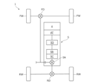
- FIG. 1 is a schematic diagram showing a drive system device of a vehicle to which a display device according to an embodiment is applied;
- FIG. 2 is a perspective view showing the periphery of a driver's seat and a passenger seat of the vehicle shown in FIG. 1 .
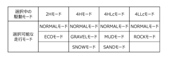
- 4 is a table showing an example of driving modes that can be selected in each drive mode.
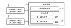
- 1 is a block diagram of a display device according to an embodiment.
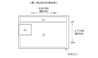
- FIG. 13 is a diagram showing a screen configuration of a second display screen displayed in a second display format.
- FIG. 13 is a diagram showing a screen configuration of a first display screen displayed in a first display format.
- 13A and 13B are diagrams showing specific examples of the first display unit, in which FIG.
- FIG. 13A shows a case where the selected drive mode is 4LLc mode
- FIG. 13B shows a case where the selected drive mode has been switched from 4LLc to 4HLc
- 11A and 11B are diagrams showing specific examples of the second display section, where FIG. 11A shows a case where the selected driving mode is ROCK mode, and FIG. 11B shows a case where the selected driving mode has been switched from ROCK mode to NORMAL mode.
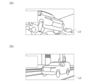
- 11A and 11B are diagrams showing specific examples of the third display section, in which (a) shows a case where the selected driving mode is the ROCK mode, and (b) shows a case where the selected driving mode is the NORMAL mode.
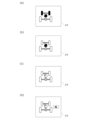
- FIG. 11A and 11B show specific examples of the fourth display section, in which (a) shows a case where the selected drive mode is 2H mode, (b) shows a case where the selected drive mode is 4H mode, (c) shows a case where the selected drive mode is 4HLc mode, and (d) shows a case where the selected drive mode is 4LLc mode.
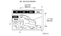
- FIG. 6 is a diagram showing a specific example of the second display screen of FIG. 5 .
- FIG. 7 is a diagram showing a specific example of the first display screen of FIG. 6.
- the forward direction of the vehicle is referred to as the forward direction (front of the vehicle), and the opposite direction is referred to as the rearward direction (rear of the vehicle).
- Left and right are defined based on the vehicle facing forward.
- the left and right direction is perpendicular to the fore-aft direction of the vehicle.
- the left and right direction is also referred to as the "vehicle width direction”
- the fore-aft direction of the vehicle is simply referred to as the "fore-aft direction”.
- the direction perpendicular to both the vehicle width direction and the fore-aft direction is defined as the up-down direction.
- FR stands for front
- RR stands for rear
- RH stands for right
- LH stands for left
- UP stands for up
- DW stands for down.
- the driving source 4 is, for example, an internal combustion engine (e.g., a gasoline engine, a diesel engine, etc.) that uses gasoline or diesel as fuel.
- the driving source 4 may also be a motor generator that functions as both an electric motor and a generator.
- the vehicle 1 may be a hybrid vehicle (HEV, Hybrid Electric Vehicle) or a plug-in hybrid vehicle (PHEV, Plug-in Hybrid Electric Vehicle) that has both an internal combustion engine and a motor generator as the driving source 4.
- a plug-in hybrid vehicle is a hybrid vehicle that allows external charging of the battery or external power supply from the battery.
- a plug-in hybrid vehicle is provided with a charging port (inlet) for inserting a charging cable that supplies power from an external charging facility and an outlet (outlet) for external power supply.
- the center differential 5A absorbs the difference in rotation between the front wheels FW and the rear wheels RW and distributes and transmits driving force.
- the center differential 5A is composed of, for example, a planetary gear mechanism.
- the switching mechanism 5B switches the connection state between the center differential 5A and the front wheels FW.
- the switching mechanism 5B is composed of, for example, multiple clutch gears and coupling sleeves connected to the center differential 5A.
- the switching mechanism 5B disconnects the center differential 5A from the front wheels FW, thereby realizing a two-wheel drive state (2H state) in which only the rear wheels RW are driven as drive wheels. Also, the switching mechanism 5B connects the center differential 5A to the front wheels FW, thereby absorbing the rotational difference between the front wheels FW and the rear wheels RW, and realizing a four-wheel drive state (4H state) in which both the front wheels FW and the rear wheels RW are driven as drive wheels.
- the locking mechanism 5C locks the differential of the center differential 5A when the center differential 5A and the front wheels FW are connected by the switching mechanism 5B.
- the locking mechanism 5C is composed of, for example, multiple clutch gears and a coupling sleeve connected to the center differential 5A.
- the sub-transmission mechanism 5D is a high/low switching mechanism that changes the driving force input to the center differential 5A (changes the rotation) when the differential of the center differential 5A is locked by the locking mechanism 5C.
- the sub-transmission mechanism 5D is composed of, for example, multiple gears, a countershaft, and a coupling sleeve.
- the sub-transmission mechanism 5D has a high gear position and a low gear position, and the high gear position and the low gear position are switched by changing the meshing of the elements that make up the sub-transmission mechanism 5D.
- the differential of the center differential 5A is locked by the lock mechanism 5C, and the sub-transmission mechanism 5D is placed in the high gear position, thereby realizing a four-wheel drive state (4HLc state) that is different from the 4H state.
- 4HLc state the rotation input to the sub-transmission mechanism 5D is directly transmitted to the center differential 5A.
- the rotation (driving force) transmitted to the center differential 5A is not differentially distributed, but is equally distributed to the front wheels FW and rear wheels RW, and both the front wheels FW and rear wheels RW are driven as drive wheels.
- the vehicle 1 is provided with a plurality of drive modes as aspects related to the drive states (2H state, 4H state, 4HLc state, and 4LLc state) realized by the transfer device 5 described above, and is provided with a drive operation switch 2 for setting the drive mode, as shown in FIG. 2.
- a drive operation switch 2 for setting the drive mode, as shown in FIG. 2.
- aspects related to the operation of the transfer device 5 i.e., the drive states realized by the transfer device 5
- the vehicle 1 is provided with a driving operation switch 3 for setting a driving mode different from the drive mode.
- the driving modes will be described later.
- the drive operation switch 2 and the driving operation switch 3 are both physical switches operated by an occupant (mainly the driver).
- the driving modes include four driving modes, 2H mode, 4H mode, 4HLc mode, and 4LLc mode, corresponding to the operation of the transfer device 5 described above.
- 2H mode the transfer device 5 realizes the 2H state
- 4H mode the transfer device 5 realizes the 4H state
- 4HLc mode the transfer device 5 realizes the 4HLc state
- 4LLc mode the transfer device 5 realizes the 4LLc state.
- the drive operation switch 2 is a switch that can select one of these four drive modes.
- the drive operation switch 2 is a rotary switch located on the top surface of the center console 1C.
- the center console 1C is a panel that extends in the front-rear direction and in the vehicle width direction between the driver's seat 1A and the passenger seat 1B.
- the drive operation switch 2 is provided with a disk portion 2A and a frame portion 2B.
- the disk portion 2A is fixed to the center console 1C and is a cylindrical or columnar member with a circular end face that faces in the same direction as the top surface of the center console 1C (i.e., upward).
- words indicating each drive mode are written on the end face of the disk portion 2A.
- the words "2H” indicating 2H mode, "4H” indicating 4H mode, "4HLc” indicating 4HLc mode, and “4LLc” indicating 4LLc mode are written in this order from the left in the circumferential direction on the front part of the disk portion 2A.
- the frame 2B is a cylindrical member that surrounds the outer periphery of the disk portion 2A, and is configured to be rotatable counterclockwise or clockwise with respect to the disk portion 2A, as shown by the dashed arrow in FIG. 2.
- a scale is engraved at one point on the circumference of the frame 2B.
- the drive operation switch 2 is operated by the occupant by rotating the frame 2B counterclockwise or clockwise so that the scale on the frame 2B points to one of the words written on the disk portion 2A.
- one of the four drive modes is alternatively selected as the "selected drive mode".
- the driving mode of this embodiment has seven driving modes: NORMAL mode, ECO mode, GRAVEL mode, SNOW mode, MUD mode, SAND mode, and ROCK mode.
- NORMAL mode NORMAL mode
- ECO mode GRAVEL mode
- SNOW mode MUD mode
- SAND mode SAND mode
- ROCK mode ROCK mode.
- one of these driving modes is selected as the "selected driving mode"
- the on-board devices for example, the drive source 4, the transmission AT, or a braking device not shown
- NORMAL mode is a mode in which preset standard control is implemented.
- ECO mode is a mode in which control is implemented that places more emphasis on fuel economy and power consumption than NORMAL mode (eco-friendly driving).
- GRAVEL mode is a mode in which control is implemented that is suitable for driving on gravel roads.
- SNOW mode is a mode in which control is implemented that is suitable for driving on snowy roads, and MUD mode is a mode in which control is implemented that is suitable for driving on muddy roads.
- SAND mode is a mode in which control is implemented that is suitable for driving on sand, and ROCK mode is a mode in which control is implemented that is suitable for driving on rocky roads.
- two or more of these seven driving modes are set to be selectable alternatively for each drive mode.
- the selected drive mode is 2H mode
- one of two modes, NORMAL mode and ECO mode can be selected.
- NORMAL mode, GRAVEL mode, and SNOW mode can be selected.
- 4H mode one of three modes, NORMAL mode, GRAVEL mode, and SNOW mode
- 4HLc mode one of three modes, NORMAL mode, MUD mode, and SAND mode
- 4LLc mode one of two modes, NORMAL mode and ROCK mode, can be selected.
- the driving operation switch 3 is a switch for selecting one of a number of selectable driving modes in the selected drive mode. As shown in FIG. 2, the driving operation switch 3 is, for example, a push switch arranged on the top surface of the center console 1C. The driving operation switch 3 is provided with a push button 3A that can be pressed downward. The driving operation switch 3 switches the selected driving mode when the occupant presses the push button 3A downward. The push button 3A returns to its original position after being pressed. In other words, the driving operation switch 3 is a momentary push switch.
- the display device 10 is a device mounted on the vehicle 1 and displays information related to two types of modes that can be set in parallel.
- One of the two types of modes includes a plurality of A first mode is provided, and one of the first modes is alternatively selected as a currently selected first mode by operating a first operation switch mounted on the vehicle.
- the other of the two types of modes (second mode) is provided with a plurality of second modes, and one of the plurality of second modes is selected by operating a second operation switch mounted on the vehicle.
- the display device 10 displays the first and second modes side by side, so that the display device 10 can display not only the selected mode but also selectable modes. This is a device that can make the occupant aware of the currently selected mode as well.
- the display device 10 comprises an electronic control device 20 and an output device 30.
- the electronic control device 20 is a computer for controlling the content displayed on the output device 30, and has a built-in processor (arithmetic processing unit) and memory (storage device).
- the processing content (program) of the electronic control device 20 is stored in the memory, and is executed by loading the content into the processor as appropriate.
- the electronic control device 20 may be formed integrally with the output device 30 (built-in to the output device 30), or may be provided separately from the output device 30.
- the output device 30 is a device that displays information related to the vehicle 1, and is, for example, a liquid crystal display, an organic EL (Electro-Luminescence) display, a projector, etc.
- the display or projector screen on which information is displayed is also referred to as the display screen 31 (screen, see Figure 5, etc.). All information displayed on the display screen 31 is controlled by the electronic control unit 20.
- the shape of the display screen 31 (the shape of the area in which information is displayed) is not particularly limited, but is, for example, rectangular. As shown in FIG. 2, the shape of the display screen 31 in this embodiment is rectangular with short sides along the up-down direction and long sides along the left-right direction. Hereinafter, the direction in which the short sides of the display screen 31 extend is also referred to as the vertical direction, and the direction in which the long sides extend is also referred to as the horizontal direction.
- the position in which the output device 30 is disposed is not particularly limited, but is preferably disposed in a position that is easy for the driver to see. In this embodiment, the output device 30 (display screen 31) is disposed in front of the driver (in front of the steering wheel).
- the display device 10 is provided with a first display section 11 for displaying information related to the drive mode and a second display section 12 for displaying information related to the running mode within a display screen 31.
- the display device 10 of this embodiment is further provided with a third display section 13 and a fourth display section 14.
- Fig. 5 is a diagram showing the screen configuration of a second display screen 31B displayed in a second display format 10B described later
- Fig. 6 is a diagram showing the screen configuration of a first display screen 31A displayed in a first display format 10A described later.
- the first display unit 11 is a section that displays multiple drive modes side by side as information related to the drive mode.
- the multiple drive modes are arranged side by side in a direction that corresponds to the operation direction of the drive operation switch 2.
- the drive operation switch 2 in this embodiment is operated in the left-right direction.
- the first display unit 11 is provided as a section that is long in the left-right direction in order to display multiple drive modes side by side in the left-right direction (horizontal direction) in response to this.
- the first display unit 11 is provided as a display area with a relatively large width dimension in the left-right direction.
- the position at which the first display unit 11 is provided within the display screen 31 is not particularly limited, but it is, for example, provided at the top of the display screen 31.
- FIGS. 7(a) and (b) are diagrams showing specific examples of the first display unit 11.
- FIG. 7(a) shows a case where the selected drive mode is 4LLc mode.
- FIG. 7(b) shows a case where the drive operation switch 2 is rotated left in the state shown in FIG. 7(a), causing the selected drive mode to change from 4LLc mode to 4HLc mode.
- the driving mode of this embodiment has four driving modes: 2H mode, 4H mode, 4HLc mode, and 4LLc mode. Therefore, the words “2H”, “4H”, “4HLc”, and “4LLc” indicating each driving mode are displayed side by side in the left-right direction on the first display unit 11, as shown in Figures 7(a) and (b).
- the selected drive mode is highlighted on the first display section 11. For example, if the selected drive mode is the 4LLc mode, the tab indicating the 4LLc mode is highlighted in a different color from the tabs indicating the other drive modes on the first display section 11, as shown in FIG. 7(a).
- the selected drive mode is switched to the left or right as the drive operation switch 2 is operated to the left or right.
- the selected drive mode is switched from 4LLc mode to 4HLc mode as the drive operation switch 2 is operated to the left
- the selected drive mode is switched to the left as shown in FIG. 7(b) in the first display unit 11.
- the tab indicating 4HLc mode located to the left of the tab indicating 4LLc mode is switched so that it is highlighted in a color different from the other drive modes.
- the second display section 12 is a section that displays multiple driving modes side by side as information related to driving behavior.
- the multiple driving modes are arranged side by side in a direction that corresponds to the operation direction of the driving operation switch 3.
- the driving operation switch 3 in this embodiment is operated in the up-down direction (downward direction) perpendicular to the left-right direction.
- the second display section 12 is provided as a section (area) that is wide in the up-down direction in order to display multiple driving modes side by side in the up-down direction (vertical direction) perpendicular to the left-right direction (horizontal direction).
- the second display unit 12 is provided within the display screen 31 , but it is preferable that it is located in a position that does not overlap with the first display unit 11. In this embodiment, the second display unit 12 is located below and to the left of the first display unit 11.
- FIGS. 8(a) and (b) are diagrams showing specific examples of the second display unit 12.
- FIG. 8(a) shows a case where the selected drive mode is 4LLc mode and the selected driving mode is ROCK mode.
- FIG. 8(b) shows a case where the driving operation switch 3 is pressed downward in the state shown in FIG. 8(a), causing the selected driving mode to change from ROCK mode to NORMAL mode.
- the selected driving mode is highlighted on the second display unit 12.
- the selected driving mode is ROCK mode
- the tab indicating ROCK mode is highlighted on the second display unit 12 in a different color than the tabs indicating other driving modes (i.e., NORMAL mode) and larger than the tabs indicating other driving modes.
- the selected driving mode is switched upward or downward as the driving operation switch 3 is operated downward.
- the driving operation switch 3 is operated downward when the selected drive mode is 4LLc mode and the selected driving mode is ROCK mode.
- the row below ROCK mode is blank. Therefore, the selected driving mode is switched to NORMAL mode, which is written in the top row of the 4LLc mode column. Accordingly, the selected driving mode is switched upward as shown in FIG. 8(b) in the second display section 12.
- the tab indicating NORMAL mode located above the tab indicating ROCK mode is switched so as to be highlighted in a color and size different from the tabs indicating other driving modes. Note that, when the driving operation switch 3 is operated downward again in the state shown in FIG. 8(b), the selected driving mode is switched downward as a result of this operation, as shown in FIG. 8(a).
- the tab indicating the selected driving mode is highlighted in a different color and size from the tabs indicating other driving modes, making it easier to grasp the selected driving mode. Also, since the arrangement direction (display direction) of the multiple driving modes displayed on the second display unit 12 and the operation direction of the driving operation switch 3 correspond (match) to each other, it becomes easier to intuitively understand that the selected driving mode can be switched with the driving operation switch 3.
- the third display section 13 is a section that displays an image of the selected driving mode.
- the position of the third display section 13 within the display screen 31 is not particularly limited, but it is preferable that it is located in a position that does not overlap with either the first display section 11 or the second display section 12. As shown in FIG. 5, the third display section 13 in this embodiment is located below the first display section 11 in an area excluding the area where the second display section 12 is displayed.
- FIGS. 9(a) and (b) are diagrams showing specific examples of the third display unit 13. Note that FIG. 9(a) shows a case where the selected driving mode is ROCK mode, and FIG. 9(b) shows a case where the selected driving mode is NORMAL mode.
- the display device 10 is provided with a number of image images representing each driving mode, and the image of the selected driving mode is appropriately displayed on the third display unit 13. This allows the occupant to intuitively recognize what driving environment (what location and road conditions) the selected driving mode is suited to.
- the fourth display section 14 is a section that displays an image of the selected driving mode.
- the position of the fourth display section 14 within the display screen 31 is not particularly limited, but it is preferable that it is at least located in a position that does not overlap with the first display section 11.
- the fourth display section 14 is located in an area of the display screen 31 that is approximately the same as the area of the third display section 13, as shown in Figures 5 and 6.
- FIGS. 10(a) to (d) are diagrams showing specific examples of the fourth display section 14. Note that FIGS. 10(a) to (d) show cases where the selected drive mode is 2H mode, 4H mode, 4HLc mode, and 4LLc mode, respectively.
- the image displayed on the fourth display unit 14 includes an image that resembles the powertrain of the vehicle 1.
- the image includes icons that resemble the front wheels FW, rear wheels RW, and transfer device 5 (lock mechanism 5C).
- these icons are displayed either lit or unlit to represent the selected drive mode. Note that in Figures 10(a) to (d), a white icon indicates that the icon is lit, and a black icon indicates that the icon is unlit.
- the selected drive mode is the 2H mode, as shown in FIG. 10(a), an image is displayed in which an icon resembling the rear wheels RW is lit and the icons resembling the front wheels FW and the locking mechanism 5C are turned off.
- the selected drive mode is the 2H mode, in which only the rear wheels RW are the drive wheels.
- the selected drive mode is the 4H mode, as shown in FIG. 10(b), an image is displayed in which the icons representing the front wheels FW and rear wheels RW are lit and the icon representing the lock mechanism 5C is turned off.
- the selected drive mode is the 4H mode, in which both the front wheels FW and rear wheels RW are drive wheels.
- the selected drive mode is the 4HLc mode
- an image is displayed in which icons representing the front wheels FW, rear wheels RW, and locking mechanism 5C are lit up, as shown in FIG. 10(c).
- the selected drive mode is the 4HLc mode, in which both the front wheels FW and rear wheels RW are drive wheels and the differential of the center differential 5A is locked.
- the selected drive mode is the 4LLc mode, as shown in FIG. 10(d), an image in which an icon surrounding the letters "4L” is lit is displayed on the image in FIG. 10(c). This allows the occupant to easily understand that the selected drive mode is the 4LLc mode in which the subtransmission mechanism 5D is in the low gear position.
- the display device 10 has two display formats for information displayed on the output device 3: a first display format 10A and a second display format 10B.
- the first display format 10A is a format for displaying information on the display screen 31 when the drive operation switch 2 is operated
- the second display format 10B is a format for displaying information on the display screen 31 when the travel operation switch 3 is operated.
- the second display format 10B has a second display screen 31B as shown in FIG. 5.
- the second display screen 31B simultaneously displays the first display section 11, the second display section 12, and the third display section 13 within the same screen.
- FIG. 11 is a diagram showing a specific example of the second display format 10B.
- FIG. 11 illustrates an example in which the selected drive mode is the 4LLc mode, and the selected running mode is the ROCK mode.
- the first display section 11 and the second display section 12 are displayed simultaneously. This allows not only the driver to grasp the information for each of the two modes, but also the relationship between the two modes. In particular, when the number of selectable driving modes increases or decreases depending on the selected drive mode, the driver can grasp the relationship between the selected drive mode and the multiple driving modes selectable in the selected drive mode. This allows the driver to be prompted to select the optimal driving mode for each drive mode.
- the second display section 12 and the third display section 13 are switched in response to the operation.
- the second display section 12 switches the selected driving mode to NORMAL mode, which is located above ROCK mode.
- the second display section 12 switches to a display that highlights the "NORMAL" tab in FIG. 8(b).
- the third display section 13 switches to display the image in FIG. 9(b) that depicts NORMAL mode.
- the first display format 10A has a first display screen 31A as shown in FIG. 6.
- the first display screen 31A simultaneously displays the first display section 11 and the fourth display section 14 within the same screen.
- FIG. 12 is a diagram showing a specific example of the first display format 10A.
- FIG. 12 illustrates an example in which the 4LLc mode is selected as the selected drive mode.
- the first display section 11 and the fourth display section 14 are switched in response to the operation.
- the first display section 11 switches to display the selected drive mode as the 4HLc mode, which is located to the left of the 4LLc mode.
- the first display section 11 switches to a display that highlights the "4HLc" tab in FIG. 7(b).
- the fourth display section 14 also switches to display the image of FIG. 10(c) that depicts 4HLc.
- the above-described display device 10 includes a first display unit 11 and a second display unit 12.
- the first display unit 11 displays a plurality of drive modes arranged in the horizontal direction of the display screen 31, which corresponds to the operation direction of the drive operation switch 2.
- the second display unit 12 displays a plurality of driving modes arranged in the vertical direction of the display screen 31, which corresponds to the operation direction of the travel operation switch 3. This allows the occupant to recognize the plurality of modes provided for each aspect (i.e., options for each aspect). This improves the usability of the display device 10.
- each switch 2 and 3 is linked to the display direction of the display units 11 and 12 that display information related to the mode set by the switches 2 and 3. Therefore, the switch related to the mode to be set can be intuitively operated. In other words, when a certain mode (e.g., a drive mode) is to be set, it is possible to prevent the occupant from erroneously operating a switch (drive operation switch 3) for setting another mode (e.g., a driving mode). This also improves the usability of the display device 10.
- a certain mode e.g., a drive mode
- the selected drive mode is highlighted on the first display section 11, and the selected driving mode is highlighted on the second display section 12. This allows the occupant to grasp the selected drive mode and the selected driving mode at a glance. This improves the usability of the display device 10.
- the drive operation switch 2 is a rotary switch that can be rotated left and right.
- the selected drive mode is switched leftward as the drive operation switch 2 is operated leftward, and the selected drive mode is switched rightward as the drive operation switch 2 is operated rightward.
- the selected drive mode is switched in the direction corresponding to (linked with) the operation of the drive operation switch 2. This makes it easy to select the intended drive mode from among multiple drive modes as the selected drive mode without having to check the wording displayed on the drive operation switch 2.
- the driving operation switch 3 is a push switch that can be operated by pressing downward.
- the selected driving mode is switched and displayed upward or downward as the driving operation switch 3 is operated downward. In this way, the selected driving mode is switched and displayed in response to (linked with) the operation of the driving operation switch 3. This makes it easy to select the intended driving mode from among multiple driving modes as the selected driving mode.
- the display device 10 described above further includes a third display unit 13 that displays an image of the selected driving mode. This allows the occupant to visually grasp the characteristics of the selected driving mode, in addition to the text information displayed on the second display unit 12. This makes it possible to encourage the occupant to select a more optimal driving mode.
- the second display screen 31B is displayed simultaneously with the first display section 11, the second display section 12, and the third display section 13. This allows the occupant to understand the characteristics of the selected driving mode, and also allows the occupant to understand the relationship between the drive mode and the driving mode.
- the above-described display device 10 is merely an example, and is not limited to the above. Furthermore, the configuration of the vehicle 1 to which the above-described display device 10 is applied is also merely an example, and is not limited to the above.
- first operation switch may be any switch that is operated at least in the left-right direction of the vehicle, and does not have to be the drive operation switch 2 for setting the drive mode, and does not have to be a rotary switch.
- second operation switch described in the claims may be any switch that is operated at least in a direction perpendicular to the operation direction of the first operation switch, and does not have to be the drive operation switch 3 for setting the drive mode, and does not have to be a push switch.
- the "first aspect” described in the claims does not have to be a drive aspect
- the "second aspect” described in the claims does not have to be a running aspect
- the first aspect may be a running aspect
- the second aspect may be a drive aspect
- each aspect is not limited to a drive aspect and a running aspect, and may be another aspect.
- the first aspect may be an aspect related to audio
- the second aspect may be an aspect related to in-vehicle air conditioning.
- the vehicle to which the display device 10 is applied does not have to be a vehicle 1 equipped with a transfer device 5 that changes the drive state of the front wheels FW and the rear wheels RW.
- the same effect as above can be obtained by displaying multiple driving modes side by side in the vertical direction (up and down direction) corresponding to the orthogonal direction.
- the selected driving mode is switched and displayed upward as the operating lever is tilted forward, and the selected driving mode is switched and displayed downward as the operating lever is tilted backward.
- the selected driving mode is switched and displayed in the direction corresponding to (linked with) the operation of the driving operation switch 3, making it easier to select the intended driving mode from among the multiple driving modes as the selected driving mode.
- the locations of the drive operation switch 2 and the driving operation switch 3 are not limited to the above positions, but may be any positions that allow the occupant (mainly the driver) to operate them.
- at least one of the drive operation switch 2 and the driving operation switch 3 may be provided on the instrument panel.
- the selected drive mode does not have to be highlighted in the first display section 11.
- the selected driving mode does not have to be highlighted in the second display section 12.
- the second display section 12 may display multiple driving modes side-by-side so that the selected driving mode is always at the front (top).
- the third display unit 13 and the fourth display unit 14 may be omitted.
- the display device 10 does not have to have two display formats, the first display format 10A and the second display format 10B, as the display format of the information displayed on the output device 3. However, it is preferable that the display device 10 has a format in which the first display unit 11 and the second display unit 12 are displayed simultaneously.
Landscapes
- Engineering & Computer Science (AREA)
- Chemical & Material Sciences (AREA)
- Combustion & Propulsion (AREA)
- Transportation (AREA)
- Mechanical Engineering (AREA)
- Arrangement And Mounting Of Devices That Control Transmission Of Motive Force (AREA)
Abstract
Description
態様6.上記の態様5において、前記画面として、前記第二操作スイッチが操作された場合に前記第一表示部と前記第二表示部と前記第三表示部とを同時に表示する第二表示画面を具備することが好ましい。
はじめに、図1~図3を参照して、本実施形態の表示装置10が適用される車両1の構成の一例を説明する。その後、本実施形態の表示装置10について詳述する。
図1は、実施例としての車両1が備える駆動系の装置(パワートレイン)を示す模式図である。車両1は、前輪FW及び後輪RWの駆動状態を変更可能である。車両1には、駆動源4、及び、駆動源4と前後車輪FW,RWとの動力伝達経路上に介装されたトランスファ装置5が設けられる。
表示装置10は、車両1に搭載されて、並列的に設定可能な二種類の態様に係る情報を表示する装置である。二種類の態様のうち一方の態様(第一態様)には、複数の第一モードが設けられており、車載の第一操作スイッチが操作されることで、複数の第一モードのうちの一つが選択中の第一モードとして択一的に選択される。また、二種類の態様のうち他方の態様(第二態様)には、複数の第二モードが設けられており、車載の第二操作スイッチが操作されることで、複数の第二モードのうちの一つが選択中の第二モードとして択一的に選択される。表示装置10は、これら複数の第一モード及び第二モードを並べて表示することで、選択中のモードだけでなく、選択可能なモード(非選択中のモード)をも乗員に認識させることができる装置である。
表示装置10には、図5に示すように、表示画面31内に、駆動態様に係る情報を表示する第一表示部11と、走行態様に係る情報を表示する第二表示部12とが設けられる。本実施形態の表示装置10には、さらに、図5及び図6に示すように、第三表示部13及び第四表示部14が設けられる。なお、図5は、後述する第二表示形式10Bで表示される第二表示画面31Bの画面構成を示す図であり、図6は、後述する第一表示形式10Aで表示される第一表示画面31Aの画面構成を示す図である。
(1)上述した表示装置10は、第一表示部11と第二表示部12とを備える。第一表示部11には、駆動操作スイッチ2の操作方向に対応する表示画面31の横方向に複数の駆動モードが並べて表示される。また、第二表示部12には、走行操作スイッチ3の操作方向に対応する表示画面31の縦方向に複数の走行モードが並べて表示される。これにより、各態様に設けられた複数のモード(すなわち、各態様の選択肢)を乗員に認識させることができる。よって、表示装置10のユーザビリティを向上することができる。
上述した表示装置10は一例であって、上述したものに限られない。また、上述した表示装置10が適用される車両1の構成も一例であって、上述したものに限らない。
2 駆動操作スイッチ(第一操作スイッチ)
3 走行操作スイッチ(第二操作スイッチ)
5 トランスファ装置
10 表示装置
11 第一表示部
12 第二表示部
13 第三表示部
14 第四表示部
31 表示画面(画面)
31A 第一表示画面
31B 第二表示画面
FW 前輪
RW 後輪
Claims (8)
- 車両に搭載される表示装置であって、
画面内に、並列的に設定可能な二種類の態様のうちの第一態様に係る情報を表示する第一表示部と、
同一の前記画面内に、前記二種類の態様のうちの第二態様に係る情報を表示する第二表示部と、を備え、
前記第一態様には、複数の第一モードが設けられており、前記車両に設けられた第一操作スイッチが前記車両の左右方向に操作されることで、前記複数の第一モードのうちの一つが選択中の第一モードとして択一的に選択され、
前記第二態様には、複数の第二モードが設けられており、前記車両に設けられた第二操作スイッチが前記左右方向に直交する直交方向に操作されることで、前記複数の第二モードのうちの一つが選択中の第二モードとして択一的に選択され、
前記第一表示部には、前記左右方向に対応する前記画面の横方向に前記複数の第一モードが並べて表示され、
前記第二表示部には、前記直交方向に対応する前記画面の縦方向に前記複数の第二モードが並べて表示される
ことを特徴とする、表示装置。 - 前記第一表示部には前記選択中の第一モードが強調表示され、前記第二表示部には前記選択中の第二モードが強調表示される
ことを特徴とする、請求項1に記載の表示装置。 - 前記第一操作スイッチは、前記左右方向に回転操作可能なロータリスイッチであり、
前記第二操作スイッチは、前記車両の下方向に押圧操作可能なプッシュスイッチであり、
前記第一表示部には、前記複数の第一モードが前記画面の左右方向に並んで表示されるとともに、前記第一操作スイッチの左方向又は右方向への操作に伴って前記選択中の第一モードが左方向又は右方向へ切り替え表示され、
前記第二表示部には、前記複数の第二モードが前記画面の上下方向に並べて表示されるとともに、前記第二操作スイッチの下方向への操作に伴って前記選択中の第二モードが上方向又は下方向へ切り替え表示される
ことを特徴とする、請求項1又は2に記載の表示装置。 - 前記第二態様には、各々の前記第一モードで選択可能な複数の第二モードが設けられており、
前記第二モードの数は、前記第一モードごとに設定されており、
前記第二表示部には、前記選択中の第一モードで選択可能な前記第二モードが並べて表示される
ことを特徴とする、請求項1~3のいずれか一項に記載の表示装置。 - 前記画面内に、前記選択中の第二モードのイメージ画像を表示する第三表示部を備える
ことを特徴とする、請求項1~4のいずれか一項に記載の表示装置。 - 前記画面として、前記第二操作スイッチが操作された場合に前記第一表示部と前記第二表示部と前記第三表示部とを同時に表示する第二表示画面を具備する
ことを特徴とする、請求項5に記載の表示装置。 - 前記画面内に、前記選択中の第一モードのイメージ画像を表示する第四表示部を備え、
前記第二モード表示画面とは別に、前記画面として、前記第一操作スイッチが操作された場合に前記第一表示部及び前記第四表示部を同時に表示する第一表示画面を具備する
ことを特徴とする、請求項6に記載の表示装置。 - 前記車両は、前輪及び後輪の駆動状態を変更するトランスファ装置を具備した車両であり、
前記第一態様は、前記トランスファ装置の作動に関する態様であり、前記複数の第一モードとしての複数の駆動モードを有し、
前記第二態様は、前記車両の走行環境に応じた走行を実現するため制御に関する態様であり、前記複数の第二モードとしての複数の走行モードを有する
ことを特徴とする、請求項1~7のいずれか一項に記載の表示装置。
Priority Applications (2)
| Application Number | Priority Date | Filing Date | Title |
|---|---|---|---|
| PCT/JP2023/011808 WO2024201564A1 (ja) | 2023-03-24 | 2023-03-24 | 表示装置 |
| JP2025509063A JPWO2024201564A1 (ja) | 2023-03-24 | 2023-03-24 |
Applications Claiming Priority (1)
| Application Number | Priority Date | Filing Date | Title |
|---|---|---|---|
| PCT/JP2023/011808 WO2024201564A1 (ja) | 2023-03-24 | 2023-03-24 | 表示装置 |
Publications (1)
| Publication Number | Publication Date |
|---|---|
| WO2024201564A1 true WO2024201564A1 (ja) | 2024-10-03 |
Family
ID=92903965
Family Applications (1)
| Application Number | Title | Priority Date | Filing Date |
|---|---|---|---|
| PCT/JP2023/011808 Ceased WO2024201564A1 (ja) | 2023-03-24 | 2023-03-24 | 表示装置 |
Country Status (2)
| Country | Link |
|---|---|
| JP (1) | JPWO2024201564A1 (ja) |
| WO (1) | WO2024201564A1 (ja) |
Citations (3)
| Publication number | Priority date | Publication date | Assignee | Title |
|---|---|---|---|---|
| JP2010149850A (ja) * | 2010-01-27 | 2010-07-08 | Toyota Motor Corp | 車両制御装置 |
| JP2012022393A (ja) * | 2010-07-12 | 2012-02-02 | Yazaki Corp | 車両用表示装置 |
| JP2019056841A (ja) * | 2017-09-21 | 2019-04-11 | マツダ株式会社 | 車両用表示装置 |
-
2023
- 2023-03-24 JP JP2025509063A patent/JPWO2024201564A1/ja active Pending
- 2023-03-24 WO PCT/JP2023/011808 patent/WO2024201564A1/ja not_active Ceased
Patent Citations (3)
| Publication number | Priority date | Publication date | Assignee | Title |
|---|---|---|---|---|
| JP2010149850A (ja) * | 2010-01-27 | 2010-07-08 | Toyota Motor Corp | 車両制御装置 |
| JP2012022393A (ja) * | 2010-07-12 | 2012-02-02 | Yazaki Corp | 車両用表示装置 |
| JP2019056841A (ja) * | 2017-09-21 | 2019-04-11 | マツダ株式会社 | 車両用表示装置 |
Also Published As
| Publication number | Publication date |
|---|---|
| JPWO2024201564A1 (ja) | 2024-10-03 |
Similar Documents
| Publication | Publication Date | Title |
|---|---|---|
| JP5624632B2 (ja) | 自動車のディスプレイおよび操作システム | |
| US8467930B2 (en) | Driving mode changing device | |
| US9381807B2 (en) | Electronic shifter limp-home techniques | |
| CN102971177B (zh) | 车辆用显示装置 | |
| JP5263186B2 (ja) | 車両制御装置 | |
| US20100222972A1 (en) | Method and Apparatus for Shift-by-Wire in a Motor Vehicle | |
| JP5850096B2 (ja) | 車両の情報表示装置 | |
| JP2001071780A (ja) | 車両用の加速・減速意思入力装置 | |
| US20220003997A1 (en) | Display device, three-dimensional display device, head-up display and vehicle | |
| JP2018006941A (ja) | 車両周辺監視装置 | |
| WO2024201564A1 (ja) | 表示装置 | |
| JP7639529B2 (ja) | 車両の走行モード切換装置及びその表示装置 | |
| JP4031786B2 (ja) | 動力出力装置およびこれを搭載する自動車 | |
| US9423021B2 (en) | Flap type electronic automatic transmission lever control method | |
| CN109296742B (zh) | 具有变速器装置的车辆 | |
| JP4867958B2 (ja) | 作業車両 | |
| JP4270165B2 (ja) | 車両の制御装置 | |
| US10514091B2 (en) | Vehicle including transmission apparatus | |
| WO2024201565A1 (ja) | 表示装置 | |
| KR20190042188A (ko) | 변속 장치를 포함하는 차량 | |
| CN114935002B (zh) | 基于组合式分动箱的过热自动换挡方法、装置、设备及介质 | |
| JP2005343191A (ja) | 動力車両の表示装置 | |
| US11623687B2 (en) | Traveling mode switching mechanism of four-wheel independent steering type vehicle | |
| US20230398992A1 (en) | Hybrid vehicle system | |
| CN113511254A (zh) | 用于轮内系统车辆的集成控制装置 |
Legal Events
| Date | Code | Title | Description |
|---|---|---|---|
| 121 | Ep: the epo has been informed by wipo that ep was designated in this application |
Ref document number: 23930206 Country of ref document: EP Kind code of ref document: A1 |
|
| DPE1 | Request for preliminary examination filed after expiration of 19th month from priority date (pct application filed from 20040101) | ||
| WWE | Wipo information: entry into national phase |
Ref document number: 2025509063 Country of ref document: JP |
|
| WWE | Wipo information: entry into national phase |
Ref document number: 2501006350 Country of ref document: TH |
|
| NENP | Non-entry into the national phase |
Ref country code: DE |
|
| 122 | Ep: pct application non-entry in european phase |
Ref document number: 23930206 Country of ref document: EP Kind code of ref document: A1 |