WO2024201561A1 - 車両用ゲート - Google Patents
車両用ゲート Download PDFInfo
- Publication number
- WO2024201561A1 WO2024201561A1 PCT/JP2023/011778 JP2023011778W WO2024201561A1 WO 2024201561 A1 WO2024201561 A1 WO 2024201561A1 JP 2023011778 W JP2023011778 W JP 2023011778W WO 2024201561 A1 WO2024201561 A1 WO 2024201561A1
- Authority
- WO
- WIPO (PCT)
- Prior art keywords
- surface portion
- reinforcement
- vehicle
- latch
- switch
- Prior art date
- Legal status (The legal status is an assumption and is not a legal conclusion. Google has not performed a legal analysis and makes no representation as to the accuracy of the status listed.)
- Ceased
Links
Images



Classifications
-
- B—PERFORMING OPERATIONS; TRANSPORTING
- B60—VEHICLES IN GENERAL
- B60J—WINDOWS, WINDSCREENS, NON-FIXED ROOFS, DOORS, OR SIMILAR DEVICES FOR VEHICLES; REMOVABLE EXTERNAL PROTECTIVE COVERINGS SPECIALLY ADAPTED FOR VEHICLES
- B60J5/00—Doors
-
- B—PERFORMING OPERATIONS; TRANSPORTING
- B60—VEHICLES IN GENERAL
- B60J—WINDOWS, WINDSCREENS, NON-FIXED ROOFS, DOORS, OR SIMILAR DEVICES FOR VEHICLES; REMOVABLE EXTERNAL PROTECTIVE COVERINGS SPECIALLY ADAPTED FOR VEHICLES
- B60J5/00—Doors
- B60J5/10—Doors arranged at the vehicle rear
Definitions
- This case concerns a vehicle gate installed on a vehicle.
- opening/closing switch has the function of transmitting an open door signal to an electronic control device upon receiving a specified input operation (e.g., pressing, touching, approaching, etc.), and having the electronic control device control the engagement state of the latch device and the locking state of the lock device.
- a specified input operation e.g., pressing, touching, approaching, etc.
- Such opening/closing switches are disposed, for example, on the edge (side edge, bottom edge) or handle of the door that is easy to place a hand on when opening the door (see Patent Documents 1 to 3).
- a vehicle gate may be subjected to some unexpected external force from outside the vehicle.
- the external force may cause the vehicle gate to deform, which may result in interference between the open/close switch and surrounding structures.
- the deformation of the vehicle gate may cause the open/close switch to change orientation, which may cause contact between the vehicle body and the operating surface of the open/close switch, resulting in the vehicle gate being opened unintentionally. It is therefore desirable for vehicle gates to be designed with a structure that suppresses interference between the open/close switch and surrounding structures even when subjected to an external force.
- One of the objectives of this case was devised in light of the above-mentioned problems, and is to provide a vehicle gate that prevents the opening/closing switch from malfunctioning due to external forces, thereby improving the protection of the vehicle interior and occupants.
- another objective of this case is to achieve effects that cannot be obtained with conventional technology, which are derived from the various configurations shown in the "Mode for carrying out the invention" described below.
- the disclosed vehicle gate can be realized as the embodiments (application examples) disclosed below, which solve at least part of the above problems.
- Each embodiment from embodiment 2 onwards is an embodiment that can be selected additionally as appropriate, and each is an embodiment that can be omitted. None of the embodiments from embodiment 2 onwards discloses an embodiment or configuration that is essential to the present case.
- the disclosed vehicle gate is formed by joining an inner panel and an outer panel, and opens and closes the rear opening of the vehicle.
- the gate includes a first reinforcement provided on the inner panel and having a hole through which a latch of a latch device is inserted, a switch provided adjacent to the outer end of the first reinforcement and operated when opening the vehicle gate, and a second reinforcement provided between the outer end of the first reinforcement and the periphery of the hole so as to extend in the front-rear direction and sandwich the switch.
- the first reinforcement is provided at a lower end of the vehicle gate, and the switch is fixed to the first reinforcement with an operating surface facing diagonally downward and forward.
- the second reinforcement is disposed so as to overlap the switch in the front-rear direction in a side view.
- the first reinforcement has a first inclined surface portion arranged above the switch in an inclined position with its normal facing downward and rearward, a second inclined surface portion arranged adjacent to the front of the first inclined surface portion in an inclined position with its normal facing downward and frontward, a latch reinforcement surface portion having the hole portion and arranged adjacent to the front of the second inclined surface portion, and a horizontal surface portion arranged approximately horizontally adjacent to the rear of the first inclined surface portion, and the second reinforcement is a bridge connecting the latch reinforcement surface portion and the horizontal surface portion.
- the first reinforcement has a pair of wall portions formed in a plane shape substantially perpendicular to the first inclined surface portion and disposed at both ends of the first inclined surface portion in the vehicle width direction, and the second reinforcement has an outer wall surface portion that is fixed to the wall portion while being in surface contact with the wall portion.
- the second reinforcement arranged to sandwich the switch is formed in a shape that extends in the front-rear direction between the vehicle outer end of the first reinforcement and the periphery of the hole.
- FIG. 2 is an exploded perspective view showing the configuration of the vehicle gate according to the embodiment;
- FIG. 2 is a vertical cross-sectional view showing the internal structure of a vehicle gate.
- 1 is a perspective view of a latch reinforcement provided inside a vehicle gate.
- FIG. 2 is a perspective view of an additional reinforcement provided inside a vehicle gate.
- FIG. 4 is a vertical cross-sectional view showing an additional reinforcement. This is a three-sided view of the latch reinforcement (single unit). A three-sided view of a latch reinforcement including an additional reinforcement and an open switch.
- the vehicle gate according to the present invention is applied to a vehicle shown in the following embodiment.
- the front-rear direction is defined based on the forward and backward direction of the vehicle
- the left-right direction is defined based on the front-rear direction.
- the up-down direction is defined based on the state in which the vehicle is stopped on a flat road surface.
- the inside-outside directions of the vehicle the direction from the outside of the vehicle toward the passenger compartment (including the luggage compartment) is defined as the inside of the vehicle direction, and the direction from the passenger compartment toward the outside of the vehicle is defined as the outside of the vehicle direction.
- the vehicle gate of this embodiment is formed hollow from panels (e.g., inner and outer panels) which are structural members forming the outer shell of the door, and a latch device and an open switch (switch) are provided inside the hollow.
- the vehicle gate incorporates a latch reinforcement (first reinforcement) which is a reinforcing member for reinforcing the latch device, and an additional reinforcement (second reinforcement) for preventing the open switch from malfunctioning due to external forces.
- first reinforcement is a reinforcing member for reinforcing the latch device
- second reinforcement additional reinforcement
- the directions of the parts and parts which constitute the vehicle gate refer to the directions based on the closed state of the vehicle gate.
- Fig. 1 is an exploded perspective view showing the configuration of a vehicle gate 1 as an embodiment
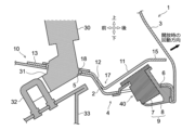
- Fig. 2 is a vertical cross-sectional view showing the internal structure of the vehicle gate 1 in a closed state.
- the vehicle gate 1 is an upward-opening rear door (tailgate, rear gate) attached to the rear end of a vehicle, and is provided so as to be able to open the vehicle compartment (including the luggage compartment) to the outside of the vehicle and to be able to maintain a closed state.
- a rear glass is fitted into the upper part of the vehicle gate 1.
- Tail lamps are attached near both the left and right ends of the vehicle gate 1.
- a known hinge mechanism and link mechanism are provided at the upper end of the vehicle gate 1. Through these mechanisms, the vehicle gate 1 is supported so as to be able to rotate upward relative to the vehicle body.
- the vehicle gate 1 is formed by joining an inner panel 2 and an outer panel 3.
- the inner panel 2 is a planar member that mainly forms the inner surface of the vehicle gate 1
- the outer panel 3 is a planar member that mainly forms the exterior (outer surface) of the vehicle gate 1.
- the inner panel 2 is provided on the inside of the vehicle, and the outer panel 3 is provided on the outside of the vehicle.
- the inner panel 2 and the outer panel 3 are arranged with a gap in between in the thickness direction of the vehicle gate 1, and are fixed with their respective peripheral edges overlapping. This makes the inside of the vehicle gate 1 covered by the inner panel 2 and outer panel 3 hollow.
- the outer panel 3 shown in FIG. 1 constitutes only the rear surface of the vehicle gate 1. Meanwhile, the inner panel 2 constitutes the front surface and the other end surfaces (top, bottom, left and right end surfaces) of the vehicle gate 1.
- a decorative door trim (lining, interior material) can be attached to the portion of the surface of the inner panel 2 that faces the passenger compartment.
- the inner panel 2 and outer panel 3 are formed, for example, from metal plate (steel plate, aluminum plate, etc.) or resin (plastic, engineering plastic, super engineering plastic, etc.).
- a latch device 30 for holding the vehicle gate 1 in a closed state, a latch reinforcement 10 (first reinforcement) and an additional reinforcement 20 (second reinforcement), which are reinforcing members for stabilizing the mounting state of the latch device 30, and an input device 9 for releasing the closed state of the vehicle gate 1 are provided near the end (lower surface 4 in this embodiment) of the end face of the vehicle gate 1.
- the latch device 30, the latch reinforcement 10, the additional reinforcement 20, and the input device 9 are provided inside the hollow of the vehicle gate 1.
- a latch opening 5 and a switch opening 6 are provided in the part of the inner panel 2 that forms the lower surface 4 of the vehicle gate 1.
- the latch device 30 is fixed near the latch opening 5 and the switch opening 6 on the end face (lower surface 4 in this embodiment) of the vehicle gate 1, and functions to hold the vehicle gate 1 in a closed state.
- the latch device 30 includes a hook-shaped latch 31 and an electric actuator for driving the latch device.
- the latch device 30 is fixed inside the vehicle gate 1 so that the latch 31 passes through the inside of the latch opening 5 and protrudes downward from the bottom surface 4.
- a striker 32 is fixed to the vehicle body so as to correspond to the position of the latch 31 when the vehicle gate 1 is closed.
- the striker 32 is a metal fitting formed by bending an axis member into a U-shape so that it can engage with the hook-shaped latch 31, for example, and is fixed near the upper end of the rear end panel 33.
- the closed state of the vehicle gate 1 is maintained by the engagement between the latch 31 and the striker 32.
- the electric actuator built into the latch device 30 is a drive device for moving the latch 31 when opening the vehicle gate 1. By operating the electric actuator, the hook-shaped latch 31 moves in a direction away from the striker 32, and the engagement between the latch 31 and the striker 32 is released.
- the latch device 30 has a built-in locking device that has the function of restricting the movement of the latch 31, but a description of this will be omitted in this embodiment.
- the input device 9 is a device operated by the occupant when activating the electric actuator.
- the input device 9 outputs a door-opening signal when a specific input operation (pressing operation, touching operation, approaching operation) is performed.
- the door-opening signal is transmitted to an electronic control device that controls the operating state of the electric actuator.
- the electronic control device receives the door-opening signal and outputs a control signal for activating the electric actuator. This activates the electric actuator, disengaging the latch device 30 and allowing the vehicle gate 1 to rotate freely.
- the input device 9 is provided near the switch opening 6.
- the input device 9 includes an open switch 7 (switch) and a switch garnish 8.
- the open switch 7 is a switch that is operated, for example, when opening or closing the vehicle gate 1, and is provided close to the outer end of the latch reinforcement 10 (rear end, in this embodiment, the horizontal surface portion 15 described later).
- the open switch 7 is provided with an operation surface 40 that is a surface that detects input operations.
- the operation surface 40 is, for example, a push switch, a touch sensor, a proximity sensor, or the like.
- the open switch 7 is arranged so that the operation surface 40 faces the end surface side (in this embodiment, the bottom surface 4 side), and is provided so that the operation surface 40 protrudes downward from the bottom surface 4 through the inside of the switch opening 6 (see FIG. 2).
- the attitude (orientation) of the open switch 7 is preferably set so that the surface of the operation surface 40 is approximately perpendicular to the rotation direction (see the black arrow in Figure 2) when the vehicle gate 1 is opened.
- the operation surface 40 is set so that it faces diagonally downward (forward and downward) toward the inner panel 2 in the thickness direction of the vehicle gate 1. This makes it easier to touch the surface of the operation surface 40 with fingertips when opening the door, and in addition, it makes it possible to rotate the vehicle gate 1 as is after inputting an input, improving operability.
- the switch garnish 8 is a member that functions as a cover that encloses the periphery of the open switch 7, and is disposed so as to surround the periphery of the operation surface 40 when engaged with the open switch 7.
- the switch garnish 8 is provided so as to close the gap between the open switch 7 and the switch opening 6 (see FIG. 2).
- the switch garnish 8 may be formed integrally with the open switch 7.
- the latch reinforcement 10 is a reinforcing member provided at the end of the vehicle gate 1 (the lower end of the vehicle gate 1 in this embodiment) and is made of, for example, a metal plate (steel plate, aluminum plate) or resin (plastic, engineering plastic, super engineering plastic, etc.).
- the latch reinforcement 10 has at least a latch hole 18 (hole portion) through which the latch 31 of the latch device 30 is inserted.
- the latch reinforcement 10 is fixed to the inner panel 2 so that the latch hole 18 overlaps with the latch opening 5. As a result, the latch hole 18 and the periphery of the latch opening 5 are reinforced by the latch reinforcement 10.
- the latch reinforcement 10 of this embodiment also has the function of covering and reinforcing the upper part of the input device 9. As shown in FIG. 2, the outer end of the latch reinforcement 10 on the vehicle side is extended so as to cover the upper part of the input device 9. Preferably, the switch garnish 8 of the input device 9 is fixed to this extended surface. This further stabilizes the mounting state of the input device 9.
- the additional reinforcement 20 is a reinforcing member that is arranged on either side of the open switch 7, and is formed, for example, from a metal plate (steel plate, aluminum plate) or a resin (plastic, engineering plastic, super engineering plastic, etc.).
- the additional reinforcement 20 is provided so as to bridge at least the vehicle outer end of the latch reinforcement 10 and the periphery of the latch hole 18.
- the additional reinforcement 20 is fixed to the latch reinforcement 10 so as to bridge between the portion of the latch reinforcement 10 that covers and reinforces the upper part of the input device 9 and the portion that reinforces the periphery of the latch hole 18.
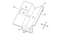
- [B. Latch Reinforcement] 3 is a perspective view of the latch reinforcement 10.
- the latch reinforcement 10 has a first inclined surface portion 11, a second inclined surface portion 12, a latch reinforcement surface portion 13, a wall portion 14, a horizontal surface portion 15, a leg portion 16, a valley portion 17, and a latch hole 18.
- the latch reinforcement 10 in this embodiment is an integrated molded product formed by pressing a single steel plate, but the latch reinforcement 10 may be manufactured by integrating multiple parts by welding or fastening.
- the first inclined surface portion 11 is a surface adjacent to the open switch 7 of the input device 9 and is a surface to which the switch garnish 8 is fixed.
- the open switch 7 is fixed to the first inclined surface portion 11 via the switch garnish 8, but the open switch 7 may be fixed directly to the first inclined surface portion 11.
- the first inclined surface portion 11 is formed in a surface shape that is inclined in a direction away from the lower surface 4 of the vehicle gate 1 toward the outside of the vehicle (the outer panel 3 side in the thickness direction of the vehicle gate 1).
- the first inclined surface portion 11 is disposed above the open switch 7 in an inclined position with its normal facing rearward and downward, as shown in FIG. 2.
- the first inclined surface portion 11 is provided above the switch opening 6 so as to face the switch opening 6, and is formed in a surface shape that is inclined so as to move away from the surface where the switch opening 6 is formed as it moves toward the outside of the vehicle (rear of the vehicle).
- the switch garnish 8 is fixed to the surface of the first inclined surface portion 11 on the lower surface 4 side (the surface facing the switch opening 6).
- the first inclined surface portion 11 in this embodiment is in the form of a surface that slopes upward toward the rear of the vehicle, and the input device 9 is attached to its lower portion.
- the first inclined surface portion 11 extends so as to form a plane that is approximately parallel to the rotation direction when the vehicle gate 1 is opened.
- the input device 9 is fixed to the first inclined surface portion 11 with the operating surface 40 of the open switch 7 facing downward and forward.
- the second inclined surface portion 12 is a planar portion extending upward and toward the inside of the vehicle (front of the vehicle) from the end edge of the first inclined surface portion 11 on the inside of the vehicle (front of the vehicle).
- the second inclined surface portion 12 is a planar portion disposed adjacent to the front of the first inclined surface portion 11 in an inclined position with its normal facing forward and downward.
- the first inclined surface portion 11 and the second inclined surface portion 12 form a V-shaped cross section.
- the boundary portion between the first inclined surface portion 11 and the second inclined surface portion 12 has a valley fold shape (valley shape).
- the valley portion 17 forming the boundary between the first inclined surface portion 11 and the second inclined surface portion 12 is disposed in a substantially straight line.
- the valley portion 17 in this embodiment extends in the vehicle width direction.
- the second inclined surface portion 12 in this embodiment is formed in a plane perpendicular to the first inclined surface portion 11, and extends to form a plane that is approximately perpendicular to the rotation direction of the vehicle gate 1 when it is opened.
- the surface of the second inclined surface portion 12 on the lower surface 4 side is arranged so as to contact, for example, the inner panel 2.
- the lower surface 4 of the inner panel 2 is arranged so as to be in surface contact with the entire second inclined surface portion 12, as shown in FIG. 2.
- the latch reinforcement surface portion 13 is a portion that reinforces the area around the latch device 30, and is a planar portion that extends from the vehicle inner edge of the second inclined surface portion 12 toward the vehicle inner side.
- a latch hole 18 that corresponds to the latch opening 5 is drilled in the latch reinforcement surface portion 13.
- the latch reinforcement surface portion 13 has the latch hole 18 and is disposed adjacent to the front of the second inclined surface portion 12.
- the latch reinforcement surface portion 13 in this embodiment is formed in a planar shape that is slightly upwardly inclined (close to horizontal) from the front end edge (upper end edge) of the second inclined surface portion 12 toward the front of the vehicle.
- the boundary between the second inclined surface portion 12 and the latch reinforcement surface portion 13 has a mountain fold shape (ridge shape) and is arranged in a substantially straight line extending in the vehicle width direction.
- the latch reinforcement surface portion 13 is formed in a planar shape that conforms to the inner panel 2 that unfolds around the latch opening 5, and is attached so as to be in surface contact with the inner panel 2 that unfolds around the latch opening 5.
- the latch device 30 is also provided so as to be in surface contact with the latch reinforcement surface portion 13. This stabilizes the engagement state between the latch 31 and the striker 32 and the operation of the latch 31.
- the wall portions 14 are vertical wall-like portions arranged in pairs at one end and the other end (both ends in the vehicle width direction) of the first inclined surface portion 11. As shown in FIG. 3, the wall portions 14 extend from both the left and right end edges of the first inclined surface portion 11 toward the underside 4, and are erected between the first inclined surface portion 11 and the end face of the vehicle gate 1 (in this embodiment, the inner panel 2 that forms the underside 4 and is positioned around the switch opening 6). The wall portions 14 are formed in a plane that is approximately perpendicular to the first inclined surface portion 11.
- the lower end of the wall 14 is provided with legs 16 formed in a plane that conforms to the inner panel 2 that unfolds around the switch opening 6.
- the legs 16 are attached so as to be in surface contact with the inner panel 2 that unfolds around the switch opening 6. This stabilizes the attachment state of the input device 9 fixed to the first inclined surface portion 11.
- the wall 14 and the legs 16 function as support members that support the first inclined surface portion 11 against the lower surface 4 (inner panel 2), preventing the first inclined surface portion 11 from moving downward or rotating.
- the horizontal surface portion 15 is a planar portion extending almost horizontally from the outer edge of the first inclined surface portion 11 on the vehicle outer side (rear side of the vehicle) to the vicinity of the outer panel 3 toward the outside of the vehicle.
- the horizontal surface portion 15 is formed as a surface extending from the rear end edge (upper end edge) of the first inclined surface portion 11 toward the rear of the vehicle.
- the horizontal surface portion 15 is disposed almost horizontally adjacent to the rear of the first inclined surface portion 11.
- the outer end edge (rear end edge) of the horizontal surface portion 15 on the vehicle outer side is preferably set in a position close to (or in contact with) the outer panel 3. If possible, it is preferable to extend the horizontal surface portion 15 so that it protrudes further outside the vehicle than the input device 9 when viewed from above.
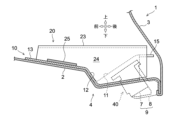
- FIG. 4 is a perspective view of the additional reinforcement 20, and FIG. 5 is a vertical cross-sectional view showing the additional reinforcement 20 in the closed state of the vehicle gate 1.
- the additional reinforcement 20 in this embodiment is provided in pairs on the right and left sides of the open switch 7.
- Each additional reinforcement 20 has a first surface portion 21, a second surface portion 22, a third surface portion 23, a fourth surface portion 24 (outer wall surface portion), and a fifth surface portion 25.
- each additional reinforcement 20 in this embodiment is an integral molded product formed by pressing a single steel plate, but the additional reinforcement 20 may be manufactured by integrating multiple parts by welding or fastening.
- the first surface portion 21 is a band-shaped portion fixed to the latch reinforcement surface portion 13 and the horizontal surface portion 15 of the latch reinforcement 10, and is provided so as to bridge between the vehicle outer end portion of the latch reinforcement 10 and the periphery of the latch hole 18 and extend in the front-rear direction.
- the first surface portion 21 is arranged so as to extend in the front-rear direction of the vehicle in a top view, for example, along the left and right side edges of the latch hole 18.
- the first surface portion 21 may be formed in a shape that is separated from the first inclined surface portion 11 and the second inclined surface portion 12, may be formed in a shape that is in partial contact with the first inclined surface portion 11 and the second inclined surface portion 12, or may be formed in a shape that is in surface contact with the first inclined surface portion 11 and the second inclined surface portion 12.
- the second surface portion 22 is a wall-like portion extending upward from one side edge of the first surface portion 21. As shown in FIG. 4, of the pair of left and right additional reinforcements 20, the second surface portion 22 of the right additional reinforcement 20 extends upward from the right side edge of the first surface portion 21. On the other hand, the second surface portion 22 of the left additional reinforcement 20 extends upward from the left side edge of the first surface portion 21.
- the third surface portion 23 is a floor plate-like portion that extends from the upper end edge of the second surface portion 22 toward the outside in the vehicle width direction. As shown in FIG. 4, of the pair of left and right additional reinforcements 20, the third surface portion 23 of the right additional reinforcement 20 extends from the upper end edge of the second surface portion 22 toward the right side. On the other hand, the third surface portion 23 of the left additional reinforcement 20 extends from the upper end edge of the second surface portion 22 toward the left side. These third surfaces 23 are arranged so as not to come into contact with the latch reinforcement 10 (so as to be suspended in mid-air). In this embodiment, the third surface portion 23 is formed in a flat shape and is arranged so as to be approximately horizontal when the vehicle gate 1 is in the closed state.
- the fourth surface portion 24 is a wall-like portion extending downward from one side edge of the third surface portion 23. As shown in FIG. 4, of the pair of left and right additional reinforcements 20, the fourth surface portion 24 of the right additional reinforcement 20 extends downward from the right side edge of the third surface portion 23. On the other hand, the fourth surface portion 24 of the left additional reinforcement 20 extends downward from the left side edge of the third surface portion 23. The lower end edge of the fourth surface portion 24 extends at least until it comes into contact with the latch reinforcement surface portion 13.
- the fourth surface portion 24 in this embodiment is disposed approximately parallel to the second surface portion 22 in each additional reinforcement 20. Furthermore, the lower end edge of the fourth surface portion 24 in this embodiment is in contact with not only the latch reinforcement surface portion 13 but also the second inclined surface portion 12 and the leg portion 16. Furthermore, the fourth surface portion 24 in this embodiment is fixed to the wall portion 14 in a state of surface contact with the wall portion 14. The contact point between the fourth surface portion 24 and the wall portion 14 is shown by hatching in Figure 4. A triangular area located at the bottom of the fourth surface portion 24 is joined integrally with the wall portion 14, reinforcing the left and right sides of the first inclined surface portion 11.
- the fifth surface portion 25 is a floor plate-like portion that extends from a portion of the lower end edge of the fourth surface portion 24 toward the outside in the vehicle width direction. Of the pair of left and right additional reinforcements 20, the fifth surface portion 25 extends toward the right in the right additional reinforcement 20, and the fifth surface portion 25 extends toward the left in the left additional reinforcement 20. As shown in FIG. 5, the fifth surface portion 25 is provided so as to be in surface contact with at least the latch reinforcement surface portion 13 of the latch reinforcement 10. The surface shape of the fifth surface portion 25 may be extended rearward to be in surface contact with the second inclined surface portion 12 or the leg portion 16.
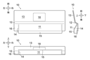
- FIG. 6 is a three-view diagram of the latch reinforcement 10
- FIG. 7 is a three-view diagram of the latch reinforcement 10 including the additional reinforcement 20 and the open switch 7.
- the upper part of the open switch 7 is disposed in the space surrounded by the first inclined surface portion 11, the wall portion 14, and the horizontal surface portion 15.
- the lower part of the open switch 7 protrudes slightly downward beyond the leg portion 16.
- the pair of additional reinforcements 20 are arranged in the front-rear direction along the left and right ends of the open switch 7, sandwiching the open switch 7 from the left and right. As shown in FIG. 5, the additional reinforcements 20 are arranged so as to overlap the open switch 7 in the front-rear direction in a side view. In other words, the positional relationship between the open switch 7 and the additional reinforcements 20 is set so that the upper part of the open switch 7 overlaps the fourth surface portion 24 in a side view. In a top view, the left and right ends of the open switch 7 each overlap the additional reinforcements 20 (first surface portion 21, third surface portion 23).
- the shape of the additional reinforcement 20 in a rear view is a hat shape with an upward convex shape (a groove shape that is open downward).
- the vehicle gate 1 of this embodiment includes a latch reinforcement 10, an open switch 7, and an additional reinforcement 20.
- the latch reinforcement 10 is provided on the inner panel 2, and has a latch hole 18 through which a latch 31 of a latch device 30 is inserted.
- the open switch 7 is operated when opening the vehicle gate 1, and is provided adjacent to a horizontal surface portion 15 which is the vehicle outer end portion of the latch reinforcement 10.
- the additional reinforcement 20 is provided so as to extend in the front-rear direction between the vehicle outer end portion (horizontal surface portion 15) of the latch reinforcement 10 and the periphery of the latch hole 18 (latch reinforcement surface portion 13), and is disposed with the open switch 7 in between.
- the additional reinforcement 20 arranged on either side of the open switch 7 is provided to extend in the front-rear direction between the vehicle outer end (horizontal surface portion 15) of the latch reinforcement 10 and the periphery of the latch hole 18 (latch reinforcement surface portion 13).
- This additional reinforcement 20 acts to increase the rigidity of the area from the horizontal surface portion 15 to the latch reinforcement surface portion 13 against external forces, and functions to suppress movement and rotation of the open switch 7 due to external forces.
- the latch reinforcement 10 is provided at the lower end of the vehicle gate 1. Also, the open switch 7 is fixed to the latch reinforcement 10 with the operation surface 40 facing diagonally downward and forward. This improves the operability when opening the vehicle gate 1 while preventing unintended opening of the vehicle gate 1 due to a rear-end collision, thereby improving the protection performance of the vehicle interior and occupants.
- the additional reinforcement 20 is positioned so as to overlap the open switch 7 in the front-rear direction in a side view.
- the latch reinforcement 10 has a first inclined surface portion 11, a second inclined surface portion 12, a latch reinforcement surface portion 13, and a horizontal surface portion 15.
- the first inclined surface portion 11 is disposed above the open switch 7 in an inclined position with its normal facing downward and rearward.
- the second inclined surface portion 12 is disposed adjacent to the front of the first inclined surface portion 11 in an inclined position with its normal facing downward and forward.
- the latch reinforcement surface portion 13 has a latch hole 18 and is disposed adjacent to the front of the second inclined surface portion 12.
- the horizontal surface portion 15 is disposed approximately horizontally adjacent to the rear of the first inclined surface portion 11.
- the additional reinforcement 20 is also provided as a bridge to connect the latch reinforcement surface portion 13 and the horizontal surface portion 15.
- first inclined surface portion 11 and the second inclined surface portion 12 form a V-shaped valley portion 17, and the open switch 7 is positioned below the first inclined surface portion 11, making it easier to layout the open switch 7 with good operability (setting the orientation of the operating surface 40).
- the rigidity of the latch reinforcement 10 and the area around the open switch 7 can be increased, and deformation such as the first inclined surface portion 11 and the second inclined surface portion 12 coming closer to each other can be suppressed. This improves the protection performance of the vehicle interior and occupants.
- the latch reinforcement 10 has wall portions 14 formed in a planar shape substantially perpendicular to the first inclined surface portion 11 and arranged in pairs at both ends of the first inclined surface portion 11 in the vehicle width direction.
- the additional reinforcement 20 has an outer wall surface portion (fourth surface portion 24) that is fixed to the wall portion 14 in a state of surface contact with the wall portion 14. In this way, by fixing the wall portion 14 and the fourth surface portion 24 in surface contact, the rigidity around the open switch 7 can be increased, and the protection performance of the vehicle interior and occupants can be improved.
- the latch reinforcement 10 having the shape shown in FIG. 3 and the additional reinforcement 20 having the shape shown in FIG. 4 are exemplified, but the specific shapes of these reinforcing members can be changed as appropriate.
- the latch reinforcement 10 has at least a latch hole 18 through which the latch 31 of the latch device 30 is inserted, and is provided at the end of the vehicle gate 1.
- the additional reinforcement 20 is provided so as to bridge between the outer end of the latch reinforcement 10 and the periphery of the latch hole 18, and is disposed on either side of the open switch 7.
- This invention can be used in the manufacturing industry of vehicle gates that are installed on the rear of the vehicle compartment, and can also be used in the manufacturing industry of vehicles equipped with vehicle gates.
Landscapes
- Engineering & Computer Science (AREA)
- Mechanical Engineering (AREA)
- Lock And Its Accessories (AREA)
Abstract
開示の車両用ゲート(1)は、インナパネル(2)とアウタパネル(3)とが接合されて形成され、車両の後部開口を開閉する車両用ゲート(1)であって、第一リンフォース(10)とスイッチ(7)と第二リンフォース(20)とを備える。第一リンフォース(10)は、インナパネル(2)に設けられ、ラッチ装置(30)のラッチが挿通される孔部(18)を有する。スイッチ(7)は、第一リンフォース(10)における車両外側端部(15)に近接して設けられ、車両用ゲート(1)を開放する際に操作される。第二リンフォース(20)は、第一リンフォース(10)における車両外側端部(15)と孔部(18)の周囲との間において前後方向に延びるように設けられ、スイッチ(7)を挟んで配置される。
Description
本件は、車両に設けられる車両用ゲートに関する。
従来、車両の側面や後面等に設けられる開閉自在の車両用ゲートにおいて、開閉状態を電気的に制御するための開閉スイッチを備えたものが知られている。開閉スイッチは、所定の入力操作(例えば押圧操作,タッチ操作,近接操作等)を受けて開扉信号を電子制御装置へと伝達し、ラッチ装置の係合状態やロック装置の施錠状態を電子制御装置に制御させる機能を持つ。このような開閉スイッチは、例えば開扉時に手を掛けやすい扉の端部(側端部,下端部)やハンドル部分に配設される(特許文献1~3参照)。
車両用ゲートには、予期しない何らかの外力が車外から作用することがある。この場合、外力を受けて車両用ゲートが変形し、開閉スイッチとその周囲の構造物とが干渉するおそれがある。例えば、車両用ゲートの変形に伴い開閉スイッチの向きが変化し、車体と開閉スイッチの操作面とが接触し、意図せず車両用ゲートが開放される可能性がある。したがって、車両用ゲートには、外力を受けても開閉スイッチとその周囲の構造物との干渉が抑制されるような構造を適用しておくことが望まれる。
なお、特許文献1~3に記載の構造のように、車両後面に配置される車両用ゲート(テールゲート,リヤゲート)においては、追突時の外力が開閉スイッチの周辺に作用することがあり、上記のような課題が顕在化しやすい。一方、外力の作用方向や作用位置は多種多様に想定されうる。したがって、上記の課題は車両用ゲートの形式(上開き式,横開き式,スライド式等)や配設位置(車両後面,車両側面,車両前面,車両上面等)や入力装置の取り付け位置(ゲート下端部,ゲート上端部,ゲート側端部,ゲート中央部等)に依存することなく生じる。
本件の目的の一つは、上記のような課題に照らして創案されたものであり、外力による開閉スイッチの誤作動を防止して車室及び乗員の保護性能を改善できるようにした車両用ゲートを提供することである。なお、この目的に限らず、後述する「発明を実施するための形態」に示す各構成から導き出される作用効果であって、従来の技術では得られない作用効果を奏することも、本件の他の目的として位置付けられる。
開示の車両用ゲートは、以下に開示する態様(適用例)として実現でき、上記の課題の少なくとも一部を解決する。態様2以降の各態様は、何れもが付加的に適宜選択されうる態様であって、何れもが省略可能な態様である。態様2以降の各態様は、何れもが本件にとって必要不可欠な態様や構成を開示するものではない。
態様1.開示の車両用ゲートは、インナパネルとアウタパネルとが接合されて形成され、車両の後部開口を開閉する車両用ゲートであって、前記インナパネルに設けられ、ラッチ装置のラッチが挿通される孔部を有する第一リンフォースと、前記第一リンフォースにおける車両外側端部に近接して設けられ、前記車両用ゲートを開放する際に操作されるスイッチと、前記第一リンフォースにおける前記車両外側端部と前記孔部の周囲との間において前後方向に延びるように設けられ、前記スイッチを挟んで配置される第二リンフォースとを備える。
態様2.上記の態様1において、前記第一リンフォースが、前記車両用ゲートの下端部に設けられ、前記スイッチが、操作面を斜め前下方に向けた姿勢で前記第一リンフォースに固定されることが好ましい。
態様3.上記の態様2において、前記第二リンフォースが、側面視で前記スイッチと前後方向に重なるように配置されることが好ましい。
態様3.上記の態様2において、前記第二リンフォースが、側面視で前記スイッチと前後方向に重なるように配置されることが好ましい。
態様4.上記の態様2又は3において、前記第一リンフォースが、法線を後下方に向けた傾斜姿勢にて前記スイッチの上方に配置される第一傾斜面部と、法線を前下方に向けた傾斜姿勢にて前記第一傾斜面部の前方に隣接配置される第二傾斜面部と、前記孔部を有して前記第二傾斜面部の前方に隣接配置されるラッチ補強面部と、前記第一傾斜面部の後方に隣接してほぼ水平に配置される水平面部とを有し、前記第二リンフォースが、前記ラッチ補強面部と前記水平面部との間を接続するように橋架されることが好ましい。
態様5.上記の態様4において、前記第一リンフォースが、前記第一傾斜面部に対してほぼ垂直な平面状に形成されて前記第一傾斜面部の車幅方向両端に一対配置される壁部を有し、前記第二リンフォースが、前記壁部と面接触した状態で前記壁部に固定される外壁面部を有することが好ましい。
開示の車両用ゲートによれば、スイッチを挟んで配置される第二リンフォースが、第一リンフォースにおける車両外側端部と孔部の周囲との間において前後方向に延びる形状に形成される。これにより、車両用ゲートに外力が作用した場合であってもスイッチとその周囲の構造物とを干渉しにくくすることができ、外力によるスイッチの誤作動を防止できる。したがって、車室及び乗員の保護性能を改善できる。
本発明に係る車両用ゲートは、以下の実施例に示す車両に適用される。本実施例における方向の定義に関して、前後方向は車両の前進後退方向を基準にして定められ、その前後方向を基準にして左右方向(車幅方向)が定められる。上下方向は、車両が平坦な路面上に停止している状態を基準にして定められる。車両の内外方向は、車外から車室(荷室を含む)へ向かう方向が車両内側方向とされ、車室から車外へ向かう方向が車両外側方向とされる。
本実施例の車両用ゲートは、扉の外殻を形成する構造部材であるパネル(例えばインナパネル及びアウタパネル)により中空に形成され、その中空の内部にラッチ装置及びオープンスイッチ(スイッチ)が設けられる。これに加えて、車両用ゲートにはラッチ装置を補強するための補強部材であるラッチリンフォース(第一リンフォース)と外力によるオープンスイッチの誤作動を防止するための追加リンフォース(第二リンフォース)とが内蔵される。車両用ゲートを構成する部品や部位についての方向は、特記しない限り、車両用ゲートの閉鎖状態を基準とした方向を意味する。
[1.構成]
[A.車両用ゲート]
図1は、実施例としての車両用ゲート1の構成を分解して示す分解斜視図であり、図2は、車両用ゲート1の閉鎖状態における内部構造を示す縦断面図である。この車両用ゲート1は、車両の後端部に取り付けられる上開き後面扉(テールゲート,リヤゲート)であり、車室(荷室を含む)を車外に対して開放可能かつ閉鎖状態を保持可能に設けられる。車両用ゲート1の上部には、リヤガラスが嵌め込まれる。車両用ゲート1の左右両端部近傍には、テールランプが取り付けられる。車両用ゲート1の上端部には、公知のヒンジ機構やリンク機構が設けられる。これらの機構を介して、車両用ゲート1は車体に対して上方に回動可能に支持される。
[A.車両用ゲート]
図1は、実施例としての車両用ゲート1の構成を分解して示す分解斜視図であり、図2は、車両用ゲート1の閉鎖状態における内部構造を示す縦断面図である。この車両用ゲート1は、車両の後端部に取り付けられる上開き後面扉(テールゲート,リヤゲート)であり、車室(荷室を含む)を車外に対して開放可能かつ閉鎖状態を保持可能に設けられる。車両用ゲート1の上部には、リヤガラスが嵌め込まれる。車両用ゲート1の左右両端部近傍には、テールランプが取り付けられる。車両用ゲート1の上端部には、公知のヒンジ機構やリンク機構が設けられる。これらの機構を介して、車両用ゲート1は車体に対して上方に回動可能に支持される。
車両用ゲート1は、インナパネル2とアウタパネル3とが接合されて形成される。インナパネル2は、おもに車両用ゲート1の内表面をなす面状の部材であり、アウタパネル3は、おもに車両用ゲート1の外装(外表面)をなす面状の部材である。インナパネル2は車両内側に設けられ、アウタパネル3は車両外側に設けられる。インナパネル2及びアウタパネル3は、車両用ゲート1の厚み方向に間隔をあけて配置され、各々の周縁が重合した状態で固定される。これにより、インナパネル2とアウタパネル3とで覆われる車両用ゲート1の内部が中空になる。
図1に示すアウタパネル3は、車両用ゲート1の表面のうち後面のみを構成する。一方、インナパネル2は、車両用ゲート1の表面のうち前面と他の端面(上下左右の端面)とを構成する。インナパネル2の表面のうち車室に面する部分には、美装用のドアトリム(内張り,内装部材)が装着されうる。インナパネル2及びアウタパネル3は、例えば金属板(鋼板,アルミ板など)や樹脂(プラスチック,エンジニアリングプラスチック,スーパーエンジニアリングプラスチックなど)で形成される。
車両用ゲート1の端面のうち、回動軸から遠い側に位置する端部(本実施例では下面4)の近傍には、車両用ゲート1の閉鎖状態を保持するためのラッチ装置30と、ラッチ装置30の取り付け状態を安定させるための補強部材であるラッチリンフォース10(第一リンフォース)及び追加リンフォース20(第二リンフォース)と、車両用ゲート1の閉鎖状態を解除するための入力装置9とが設けられる。これらのラッチ装置30,ラッチリンフォース10,追加リンフォース20,入力装置9は、車両用ゲート1の中空の内部に設けられる。また、インナパネル2のうち車両用ゲート1の下面4をなす部位には、ラッチ開口部5及びスイッチ開口部6が設けられる。ラッチ装置30は、車両用ゲート1の端面(本実施例では下面4)におけるラッチ開口部5及びスイッチ開口部6の近傍に固定されて、車両用ゲート1の閉鎖状態を保持するように機能する。
ラッチ装置30には、図2に示すように、鉤型に形成されるラッチ31とこれを駆動するための電動アクチュエータとが含まれる。ラッチ装置30は、ラッチ31がラッチ開口部5の内側を通って下面4よりも下方へ突出するように、車両用ゲート1の内部に固定される。また、車体側には、車両用ゲート1の閉鎖時におけるラッチ31の位置に対応するようにストライカー32が固定される。ストライカー32は、例えば鉤型のラッチ31に係合しうる軸部材をU字形に屈曲させてなる金具であり、リヤエンドパネル33の上端部近傍に固定される。
車両用ゲート1の閉鎖状態は、ラッチ31とストライカー32との係合によって保持される。また、ラッチ装置30に内蔵される電動アクチュエータは、車両用ゲート1を開放する際にラッチ31を移動させるための駆動装置である。電動アクチュエータを作動させることで、鉤型のラッチ31がストライカー32から離隔する方向へと移動し、ラッチ31とストライカー32との係合が解除される。ラッチ装置30には、ラッチ31の移動を拘束する機能を持つロック装置が内蔵されるが、本実施例ではその説明を省略する。
入力装置9は、電動アクチュエータを作動させる際に、乗員によって操作される装置である。入力装置9は、所定の入力操作(押圧操作,タッチ操作,近接操作)がなされたときに開扉信号を出力する。開扉信号は、上記の電動アクチュエータの作動状態を制御する電子制御装置に伝達される。電子制御装置は、開扉信号を受けて電動アクチュエータを作動させるための制御信号を出力する。これにより、電動アクチュエータが作動してラッチ装置30の係合状態が解除され、車両用ゲート1を自由に回動させられる状態になる。入力装置9は、スイッチ開口部6の近傍に設けられる。
入力装置9には、オープンスイッチ7(スイッチ)とスイッチガーニッシュ8とが含まれる。オープンスイッチ7は、例えば車両用ゲート1を開放する際や閉鎖する際に操作されるスイッチであり、ラッチリンフォース10における車両外側端部(後端部,本実施例では後述する水平面部15)に近接して設けられる。オープンスイッチ7には、入力操作を検出する面である操作面40が設けられる。操作面40は、例えばプッシュスイッチ,タッチセンサ,近接センサなどである。オープンスイッチ7は、操作面40が端面側(本実施例では下面4側)に向くよう配置され、例えばスイッチ開口部6の内側を通って操作面40が下面4よりも下方へ突出するように設けられる(図2参照)。
オープンスイッチ7の姿勢(向き)は、好ましくは操作面40の表面が車両用ゲート1の開放時の回動方向(図2中の黒矢印参照)に対してほぼ直交するように設定される。本実施例では、操作面40が車両用ゲート1の厚み方向におけるインナパネル2側である斜め前下方(前方かつ下方)を向くように設定される。これにより、開扉時に指先で操作面40の表面に触れやすくなり、加えて、入力操作後にそのまま車両用ゲート1を回動させることが可能となり、操作性が向上する。
スイッチガーニッシュ8は、オープンスイッチ7の周囲を被覆するカバーとして機能する部材であり、オープンスイッチ7と係合した状態で操作面40の周囲を囲むように配置される。スイッチガーニッシュ8は、オープンスイッチ7とスイッチ開口部6との隙間を塞ぐように設けられる(図2参照)。スイッチガーニッシュ8は、オープンスイッチ7と一体に形成されてもよい。
ラッチリンフォース10は、車両用ゲート1の端部(本実施例では車両用ゲート1の下端部)に設けられる補強部材であり、例えば金属板(鋼板,アルミ板)や樹脂(プラスチック,エンジニアリングプラスチック,スーパーエンジニアリングプラスチックなど)で形成される。ラッチリンフォース10は、少なくともラッチ装置30のラッチ31が挿通されるラッチ孔18(孔部)を有する。また、ラッチリンフォース10は、ラッチ孔18がラッチ開口部5と重なるようにインナパネル2に対して固定される。これにより、ラッチ孔18及びラッチ開口部5の周囲がラッチリンフォース10によって補強される。
本実施例のラッチリンフォース10は、入力装置9の上方を被覆して補強する機能を併せ持つ。図2に示すように、ラッチリンフォース10の車両外側端部は、入力装置9の上方を被覆するように延設される。好ましくは、この延設された面に対して入力装置9のスイッチガーニッシュ8が固定される。これにより、入力装置9の取り付け状態がさらに安定する。
図1に示すように、追加リンフォース20は、オープンスイッチ7を挟んで配置される補強部材であり、例えば金属板(鋼板,アルミ板)や樹脂(プラスチック,エンジニアリングプラスチック,スーパーエンジニアリングプラスチックなど)で形成される。追加リンフォース20は、少なくともラッチリンフォース10における車両外側端部とラッチ孔18の周囲との間を橋架するように設けられる。言い換えれば、追加リンフォース20はラッチリンフォース10のうち、入力装置9の上方を被覆して補強する部分とラッチ孔18の周囲を補強する部分との間を橋渡しするように、ラッチリンフォース10に対して固定される。
[B.ラッチリンフォース]
図3は、ラッチリンフォース10の斜視図である。ラッチリンフォース10は、第一傾斜面部11,第二傾斜面部12,ラッチ補強面部13,壁部14,水平面部15,脚部16,谷間部17,ラッチ孔18を有する。本実施例のラッチリンフォース10は、一枚の鋼板をプレス加工してなる一体の成形品であるが、複数の部品を溶接や締結により一体化することでラッチリンフォース10を製造してもよい。
図3は、ラッチリンフォース10の斜視図である。ラッチリンフォース10は、第一傾斜面部11,第二傾斜面部12,ラッチ補強面部13,壁部14,水平面部15,脚部16,谷間部17,ラッチ孔18を有する。本実施例のラッチリンフォース10は、一枚の鋼板をプレス加工してなる一体の成形品であるが、複数の部品を溶接や締結により一体化することでラッチリンフォース10を製造してもよい。
第一傾斜面部11は、入力装置9のオープンスイッチ7が近接して設けられる面であって、スイッチガーニッシュ8が固定される面である。本実施例のオープンスイッチ7は、スイッチガーニッシュ8を介して第一傾斜面部11に固定されるが、オープンスイッチ7を直接的に第一傾斜面部11に固定してもよい。第一傾斜面部11は、車両用ゲート1に取り付けられた状態において、車両外側(車両用ゲート1の厚み方向におけるアウタパネル3側)に向かって車両用ゲート1の下面4から離隔する方向に傾斜した面状に形成される。言い換えれば、第一傾斜面部11は、図2に示すように、法線を後下方に向けた傾斜姿勢でオープンスイッチ7の上方に配置される。
ここで、インナパネル2のうちスイッチ開口部6が形成される面と第一傾斜面部11との関係に着目する。第一傾斜面部11は、図2に示すように、スイッチ開口部6の上方においてスイッチ開口部6と対向するように設けられ、車両外側(車両後方)に向かうほどスイッチ開口部6が形成される面から離隔するように傾斜した面状に形成される。
また、スイッチガーニッシュ8は、第一傾斜面部11の表面のうち下面4側の面(スイッチ開口部6に対向する面)に対して固定される。本実施例の第一傾斜面部11は、図2に示すように、車両後方に向かって上り勾配に傾斜した面状となっており、その下部に入力装置9が取り付けられる。第一傾斜面部11は、車両用ゲート1の開放時の回動方向に対してほぼ平行な平面をなすように延在している。入力装置9は、オープンスイッチ7の操作面40を前下方に向けた状態で第一傾斜面部11に固定される。
第二傾斜面部12は、第一傾斜面部11における車両内側(車両前方)の端辺から、上方かつ車両内側(車両前方)に向かって延設される面状の部位である。言い換えれば、第二傾斜面部12は、法線を前下方に向けた傾斜姿勢で第一傾斜面部11の前方に隣接配置される面状の部位である。図2に示すように、第一傾斜面部11及び第二傾斜面部12はV字状の断面を形成する。第一傾斜面部11と第二傾斜面部12との境界部分は、谷折り形状(谷形状)となる。第一傾斜面部11と第二傾斜面部12との境界をなす谷間部17は、ほぼ直線状に配設される。本実施例の谷間部17は、車幅方向に延在している。
また、本実施例の第二傾斜面部12は、第一傾斜面部11に対して直交する平面状に形成され、車両用ゲート1の開放時の回動方向に対してほぼ直交する平面をなすように延在している。第二傾斜面部12の表面のうち下面4側の面は、例えばインナパネル2に接触するように設けられる。なお、本実施例におけるインナパネル2の下面4は、図2に示すように、第二傾斜面部12の全体に対して面接触するように設けられる。
ラッチ補強面部13は、ラッチ装置30のまわりを補強する部位であり、第二傾斜面部12における車両内側の端辺から車両内側に向かって延設される面状の部位である。ラッチ補強面部13には、ラッチ開口部5に対応するラッチ孔18が穿孔される。言い換えれば、ラッチ補強面部13は、ラッチ孔18を有して第二傾斜面部12の前方に隣接配置される。本実施例のラッチ補強面部13は、第二傾斜面部12の前端辺(上端辺)から車両前方に向かって若干上り勾配に傾斜した(水平に近い)面状に形成されている。
図2に示すように、第二傾斜面部12とラッチ補強面部13との境界部分は山折り形状(峰形状)であり、車幅方向に延在するようにほぼ直線状に配置される。また、ラッチ補強面部13は、ラッチ開口部5の周囲に展開されるインナパネル2に沿った面状に形成され、ラッチ開口部5の周囲に展開されるインナパネル2の上に面接触するように取り付けられる。同様に、ラッチ装置30もラッチ補強面部13の上に面接触するように設けられる。これにより、ラッチ31とストライカー32との係合状態やラッチ31の動作が安定する。
壁部14は、第一傾斜面部11の一端及び他端(車幅方向の両端)に一対配置される縦壁状の部位である。図3に示すように、壁部14は、第一傾斜面部11の左右両端辺から下面4に向かって延設され、第一傾斜面部11と車両用ゲート1の端面(本実施例では下面4をなしてスイッチ開口部6の周囲に位置するインナパネル2)との間に立設される。壁部14は、第一傾斜面部11に対してほぼ垂直な平面状に形成される。
壁部14の下端には、スイッチ開口部6の周囲に展開されるインナパネル2に沿った面状に形成される脚部16が設けられる。脚部16は、スイッチ開口部6の周囲に展開されるインナパネル2の上に面接触するように取り付けられる。これにより、第一傾斜面部11に固定される入力装置9の取り付け状態が安定する。また、壁部14及び脚部16は、下面4(インナパネル2)に対して第一傾斜面部11を支える支持部材として機能するため、第一傾斜面部11の下方への移動や回動が阻止される。
水平面部15は、第一傾斜面部11における車両外側(車両後側)の端辺からアウタパネル3の近傍まで車両外側に向かってほぼ水平に延設される面状の部位である。本実施例の水平面部15は、第一傾斜面部11の後端辺(上端辺)から車両後方に向かって延設される面状に形成されている。水平面部15は、第一傾斜面部11の後方に隣接してほぼ水平に配置される。水平面部15の車両外側の端辺(後端辺)は、好ましくはアウタパネル3に近接した位置(あるいは接触する位置)に設定される。可能であれば、上面視において入力装置9よりも車両外側に突出するように、水平面部15を長く延ばすことが好ましい。
[C.追加リンフォース]
図4は、追加リンフォース20の斜視図であり、図5は、車両用ゲート1の閉鎖状態における追加リンフォース20を示す縦断面図である。本実施例の追加リンフォース20は、オープンスイッチ7の右側と左側とに対をなして設けられる。各々の追加リンフォース20は、第一面部21,第二面部22,第三面部23,第四面部24(外壁面部),第五面部25を有する。左右の追加リンフォース20を一体の成形品として製造することも可能である。また、本実施例における各々の追加リンフォース20は、一枚の鋼板をプレス加工してなる一体の成形品であるが、複数の部品を溶接や締結により一体化することで追加リンフォース20を製造してもよい。
図4は、追加リンフォース20の斜視図であり、図5は、車両用ゲート1の閉鎖状態における追加リンフォース20を示す縦断面図である。本実施例の追加リンフォース20は、オープンスイッチ7の右側と左側とに対をなして設けられる。各々の追加リンフォース20は、第一面部21,第二面部22,第三面部23,第四面部24(外壁面部),第五面部25を有する。左右の追加リンフォース20を一体の成形品として製造することも可能である。また、本実施例における各々の追加リンフォース20は、一枚の鋼板をプレス加工してなる一体の成形品であるが、複数の部品を溶接や締結により一体化することで追加リンフォース20を製造してもよい。
第一面部21は、ラッチリンフォース10のラッチ補強面部13と水平面部15とに固定される帯状の部位であり、ラッチリンフォース10の車両外側端部とラッチ孔18の周囲との間を架橋して前後方向に延びるように設けられる。第一面部21は、例えばラッチ孔18の左右側縁に沿って、上面視で車両前後方向に延在するように配置される。第一面部21は、第一傾斜面部11及び第二傾斜面部12から離隔する形状に形成してもよいし、第一傾斜面部11や第二傾斜面部12に対して部分的に接触する形状に形成してもよく、第一傾斜面部11及び第二傾斜面部12に面接触する形状に形成してもよい。
第二面部22は、第一面部21の一側辺から上方に向かって延設される壁状の部位である。図4に示すように、左右一対の追加リンフォース20のうち、右側の追加リンフォース20においては、第一面部21の右側辺から上方に向かって第二面部22が延設される。一方、左側の追加リンフォース20においては、第一面部21の左側辺から上方に向かって第二面部22が延設される。
第三面部23は、第二面部22の上端辺から車幅方向外側に向かって延設される床板状の部位である。図4に示すように、左右一対の追加リンフォース20のうち、右側の追加リンフォース20においては、第二面部22の上端辺から右側に向かって第三面部23が延設される。一方、左側の追加リンフォース20においては、第二面部22の上端辺から左側に向かって第三面部23が延設される。これらの第三面部23は、ラッチリンフォース10に対して接触しない(宙に浮いた状態になる)ように設けられる。本実施例の第三面部23は平面状に形成され、車両用ゲート1の閉鎖状態においてほぼ水平になるように設けられる。
第四面部24は、第三面部23の一側辺から下方に向かって延設される壁状の部位である。図4に示すように、左右一対の追加リンフォース20のうち、右側の追加リンフォース20においては、第三面部23の右側辺から下方に向かって第四面部24が延設される。一方、左側の追加リンフォース20においては、第三面部23の左側辺から下方に向かって第四面部24が延設される。第四面部24の下端辺は、少なくともラッチ補強面部13に接触するまで延設される。
本実施例の第四面部24は、各々の追加リンフォース20において第二面部22に対してほぼ平行に配置される。また、本実施例の第四面部24の下端辺は、ラッチ補強面部13だけでなく第二傾斜面部12及び脚部16にも接触している。さらに、本実施例の第四面部24は、壁部14に対して面接触した状態で壁部14に固定される。第四面部24と壁部14との接触箇所を図4中にハッチングで示す。第四面部24の下部に位置する三角形状の領域が壁部14と一体に接合され、第一傾斜面部11の左右側方が補強される。
第五面部25は、第四面部24の下端辺の一部分から車幅方向外側に向かって延設される床板状の部位である。左右一対の追加リンフォース20のうち、右側の追加リンフォース20においては、右側に向かって第五面部25が延設され、左側の追加リンフォース20においては、左側に向かって第五面部25が延設される。第五面部25は、図5に示すように、少なくともラッチリンフォース10のラッチ補強面部13に対して面接触するように設けられる。なお、第五面部25の面形状を後方に延ばして、第二傾斜面部12や脚部16に対して面接触させてもよい。
図6は、ラッチリンフォース10の三面図であり、図7は、追加リンフォース20及びオープンスイッチ7を含むラッチリンフォース10の三面図である。図6,図7に示すように、オープンスイッチ7の上部は、第一傾斜面部11と壁部14と水平面部15とに囲まれる空間内に配置される。オープンスイッチ7の下部は、脚部16よりも下方に若干はみ出している。
一対の追加リンフォース20は、オープンスイッチ7の左端部及び右端部の各々に沿って前後方向に配置され、オープンスイッチ7を左右から挟むように配置される。また、図5に示すように、追加リンフォース20は、側面視でオープンスイッチ7と前後方向に重なるように配置される。言い換えれば、側面視でオープンスイッチ7の上部が第四面部24に重なるように、オープンスイッチ7と追加リンフォース20との位置関係が設定される。上面視においては、オープンスイッチ7の左端部及び右端部の各々が追加リンフォース20(第一面部21,第三面部23)に重なっている。また、後面視における追加リンフォース20の形状は、上に凸のハット型(下方が開放された溝型)となっている。
[2.効果]
(1)本実施例の車両用ゲート1は、ラッチリンフォース10とオープンスイッチ7と追加リンフォース20とを備える。ラッチリンフォース10は、インナパネル2に設けられ、ラッチ装置30のラッチ31が挿通されるラッチ孔18を有する。オープンスイッチ7は、車両用ゲート1を開放する際に操作されるものであり、ラッチリンフォース10における車両外側端部である水平面部15に近接して設けられる。追加リンフォース20は、ラッチリンフォース10における車両外側端部(水平面部15)とラッチ孔18の周囲(ラッチ補強面部13)との間において前後方向に延びるように設けられ、オープンスイッチ7を挟んで配置される。
(1)本実施例の車両用ゲート1は、ラッチリンフォース10とオープンスイッチ7と追加リンフォース20とを備える。ラッチリンフォース10は、インナパネル2に設けられ、ラッチ装置30のラッチ31が挿通されるラッチ孔18を有する。オープンスイッチ7は、車両用ゲート1を開放する際に操作されるものであり、ラッチリンフォース10における車両外側端部である水平面部15に近接して設けられる。追加リンフォース20は、ラッチリンフォース10における車両外側端部(水平面部15)とラッチ孔18の周囲(ラッチ補強面部13)との間において前後方向に延びるように設けられ、オープンスイッチ7を挟んで配置される。
上記の車両用ゲート1によれば、オープンスイッチ7を挟んで配置される追加リンフォース20が、ラッチリンフォース10における車両外側端部(水平面部15)とラッチ孔18の周囲(ラッチ補強面部13)との間において前後方向に延びるように設けられる。この追加リンフォース20は、外力に対して水平面部15からラッチ補強面部13にかけて部位の剛性を高めるように作用し、外力によるオープンスイッチ7の移動や回転を抑制するように機能する。
これにより、オープンスイッチ7とその周囲の構造物(例えば、ラッチリンフォース10,インナパネル2,ラッチ装置30,ラッチ31,ストライカー32,リヤエンドパネル33等)とを干渉しにくくすることができ、外力によるオープンスイッチ7の誤作動を生じにくくすることができる。したがって、意図しない車両用ゲート1の開放を防止でき、車室及び乗員の保護性能を改善できる。
(2)上記の実施例では、ラッチリンフォース10が車両用ゲート1の下端部に設けられる。また、オープンスイッチ7が、操作面40を斜め前下方に向けた姿勢でラッチリンフォースに10固定される。これにより、車両用ゲート1を開放する際の操作性を改善しつつ、後突による車両用ゲート1の意図しない開放を抑制でき、車室及び乗員の保護性能を改善できる。
(3)上記の実施例では、図5に示すように、追加リンフォース20が、側面視でオープンスイッチ7と前後方向に重なるように配置される。これにより、外力がオープンスイッチ7に対して車両後方から前方に向かって入力されたとしても、その外力を追加リンフォース20で確実に受け止めることができ、オープンスイッチ7とその周囲の構造物との干渉をより確実に防止できる。したがって、車室及び乗員の保護性能を改善できる。
(4)上記の実施例では、図3,図6に示すように、ラッチリンフォース10が第一傾斜面部11と第二傾斜面部12とラッチ補強面部13と水平面部15とを有する。第一傾斜面部11は、法線を後下方に向けた傾斜姿勢でオープンスイッチ7の上方に配置される。第二傾斜面部12は、法線を前下方に向けた傾斜姿勢で第一傾斜面部11の前方に隣接配置される。ラッチ補強面部13は、ラッチ孔18を有して第二傾斜面部12の前方に隣接配置される。水平面部15は、第一傾斜面部11の後方に隣接してほぼ水平に配置される。また、追加リンフォース20は、ラッチ補強面部13と水平面部15との間を接続するように橋架される。
このように、第一傾斜面部11及び第二傾斜面部12でV字状の谷間部17を形成し、第一傾斜面部11の下方にオープンスイッチ7を配置することで、操作性のよいオープンスイッチ7のレイアウト(操作面40の向き設定)が容易となる。また、第一傾斜面部11及び第二傾斜面部12で構成されるV字状の谷間部17に追加リンフォース20を架け渡すことで、ラッチリンフォース10やオープンスイッチ7まわりの剛性を高めることができ、第一傾斜面部11と第二傾斜面部12とが接近するような変形を抑制できる。したがって、車室及び乗員の保護性能を改善できる。
(5)上記の実施例では、図3,図6に示すように、ラッチリンフォース10が、第一傾斜面部11に対してほぼ垂直な平面状に形成されて第一傾斜面部11の車幅方向両端に一対配置される壁部14を有する。また、図4,図7に示すように、追加リンフォース20が、壁部14と面接触した状態で壁部14に固定される外壁面部(第四面部24)を有する。このように、壁部14と第四面部24とを面接触させて固定することで、オープンスイッチ7まわりの剛性を高めることができ、車室及び乗員の保護性能を改善できる。
[3.その他]
上記の実施例はあくまでも例示に過ぎず、本実施例で明示しない種々の変形や技術の適用を排除する意図はない。本実施例の各構成は、それらの趣旨を逸脱しない範囲で種々変形して実施できる。また、本実施例の各構成は必要に応じて取捨選択でき、あるいは、公知技術に含まれる各種構成と適宜組み合わせることができる。
上記の実施例はあくまでも例示に過ぎず、本実施例で明示しない種々の変形や技術の適用を排除する意図はない。本実施例の各構成は、それらの趣旨を逸脱しない範囲で種々変形して実施できる。また、本実施例の各構成は必要に応じて取捨選択でき、あるいは、公知技術に含まれる各種構成と適宜組み合わせることができる。
上記の実施例では、図3に示す形状のラッチリンフォース10と図4に示す形状の追加リンフォース20とを例示したが、これらの補強部材の具体的な形状は適宜変更可能である。ラッチリンフォース10は、少なくともラッチ装置30のラッチ31が挿通されるラッチ孔18を有するものであって、車両用ゲート1の端部に設けられたものであればよい。また、追加リンフォース20は、ラッチリンフォース10における車両外側端部とラッチ孔18の周囲との間を橋架するように設けられて、オープンスイッチ7を挟んで配置されたものであればよい。これらの構成により、上述の実施例と同様の作用効果を奏する車両用ゲート1が実現されうる。
本件は、車両の車室後面に設けられる車両用ゲートの製造産業に利用可能であるとともに、車両用ゲートを備えた車両の製造産業に利用可能である。
1 車両用ゲート
2 インナパネル
3 アウタパネル
4 下面(端面,車両用ゲートの端部)
5 ラッチ開口部
6 スイッチ開口部
7 オープンスイッチ(スイッチ)
8 スイッチガーニッシュ
9 入力装置
10 ラッチリンフォース(第一リンフォース)
11 第一傾斜面部
12 第二傾斜面部
13 ラッチ補強面部
14 壁部
15 水平面部(車両外側端部)
16 脚部
17 谷間部
18 ラッチ孔(孔部)
20 追加リンフォース(第二リンフォース)
21 第一面部
22 第二面部
23 第三面部
24 第四面部(外壁面部)
25 第五面部
30 ラッチ装置
31 ラッチ
32 ストライカー
33 リヤエンドパネル
40 操作面
2 インナパネル
3 アウタパネル
4 下面(端面,車両用ゲートの端部)
5 ラッチ開口部
6 スイッチ開口部
7 オープンスイッチ(スイッチ)
8 スイッチガーニッシュ
9 入力装置
10 ラッチリンフォース(第一リンフォース)
11 第一傾斜面部
12 第二傾斜面部
13 ラッチ補強面部
14 壁部
15 水平面部(車両外側端部)
16 脚部
17 谷間部
18 ラッチ孔(孔部)
20 追加リンフォース(第二リンフォース)
21 第一面部
22 第二面部
23 第三面部
24 第四面部(外壁面部)
25 第五面部
30 ラッチ装置
31 ラッチ
32 ストライカー
33 リヤエンドパネル
40 操作面
Claims (5)
- インナパネルとアウタパネルとが接合されて形成され、車両の後部開口を開閉する車両用ゲートであって
前記インナパネルに設けられ、ラッチ装置のラッチが挿通される孔部を有する第一リンフォースと、
前記第一リンフォースにおける車両外側端部に近接して設けられ、前記車両用ゲートを開放する際に操作されるスイッチと、
前記第一リンフォースにおける前記車両外側端部と前記孔部の周囲との間において前後方向に延びるように設けられ、前記スイッチを挟んで配置される第二リンフォースと
を備えることを特徴とする、車両用ゲート。 - 前記第一リンフォースが、前記車両用ゲートの下端部に設けられ、
前記スイッチが、操作面を斜め前下方に向けた姿勢で前記第一リンフォースに固定される
ことを特徴とする、請求項1記載の車両用ゲート。 - 前記第二リンフォースが、側面視で前記スイッチと前後方向に重なるように配置される
ことを特徴とする、請求項2記載の車両用ゲート。 - 前記第一リンフォースが、法線を後下方に向けた傾斜姿勢にて前記スイッチの上方に配置される第一傾斜面部と、法線を前下方に向けた傾斜姿勢にて前記第一傾斜面部の前方に隣接配置される第二傾斜面部と、前記孔部を有して前記第二傾斜面部の前方に隣接配置されるラッチ補強面部と、前記第一傾斜面部の後方に隣接してほぼ水平に配置される水平面部とを有し、
前記第二リンフォースが、前記ラッチ補強面部と前記水平面部との間を接続するように橋架される
ことを特徴とする、請求項2又は3記載の車両用ゲート。 - 前記第一リンフォースが、前記第一傾斜面部に対してほぼ垂直な平面状に形成されて前記第一傾斜面部の車幅方向両端に一対配置される壁部を有し、
前記第二リンフォースが、前記壁部と面接触した状態で前記壁部に固定される外壁面部を有する
ことを特徴とする、請求項4記載の車両用ゲート。
Priority Applications (2)
| Application Number | Priority Date | Filing Date | Title |
|---|---|---|---|
| JP2025509061A JPWO2024201561A1 (ja) | 2023-03-24 | 2023-03-24 | |
| PCT/JP2023/011778 WO2024201561A1 (ja) | 2023-03-24 | 2023-03-24 | 車両用ゲート |
Applications Claiming Priority (1)
| Application Number | Priority Date | Filing Date | Title |
|---|---|---|---|
| PCT/JP2023/011778 WO2024201561A1 (ja) | 2023-03-24 | 2023-03-24 | 車両用ゲート |
Publications (1)
| Publication Number | Publication Date |
|---|---|
| WO2024201561A1 true WO2024201561A1 (ja) | 2024-10-03 |
Family
ID=92904008
Family Applications (1)
| Application Number | Title | Priority Date | Filing Date |
|---|---|---|---|
| PCT/JP2023/011778 Ceased WO2024201561A1 (ja) | 2023-03-24 | 2023-03-24 | 車両用ゲート |
Country Status (2)
| Country | Link |
|---|---|
| JP (1) | JPWO2024201561A1 (ja) |
| WO (1) | WO2024201561A1 (ja) |
Citations (5)
| Publication number | Priority date | Publication date | Assignee | Title |
|---|---|---|---|---|
| JPH0960372A (ja) * | 1995-08-25 | 1997-03-04 | Nissan Motor Co Ltd | バックドアのドアロック取付構造 |
| JP2012092598A (ja) * | 2010-10-28 | 2012-05-17 | Shiroki Corp | ドアロック装置 |
| JP2014218891A (ja) * | 2014-07-07 | 2014-11-20 | シロキ工業株式会社 | ドアロック装置 |
| JP2015039991A (ja) * | 2013-08-23 | 2015-03-02 | マツダ株式会社 | 後部車体構造 |
| JP2019026036A (ja) * | 2017-07-28 | 2019-02-21 | ダイハツ工業株式会社 | 車両構造 |
-
2023
- 2023-03-24 JP JP2025509061A patent/JPWO2024201561A1/ja active Pending
- 2023-03-24 WO PCT/JP2023/011778 patent/WO2024201561A1/ja not_active Ceased
Patent Citations (5)
| Publication number | Priority date | Publication date | Assignee | Title |
|---|---|---|---|---|
| JPH0960372A (ja) * | 1995-08-25 | 1997-03-04 | Nissan Motor Co Ltd | バックドアのドアロック取付構造 |
| JP2012092598A (ja) * | 2010-10-28 | 2012-05-17 | Shiroki Corp | ドアロック装置 |
| JP2015039991A (ja) * | 2013-08-23 | 2015-03-02 | マツダ株式会社 | 後部車体構造 |
| JP2014218891A (ja) * | 2014-07-07 | 2014-11-20 | シロキ工業株式会社 | ドアロック装置 |
| JP2019026036A (ja) * | 2017-07-28 | 2019-02-21 | ダイハツ工業株式会社 | 車両構造 |
Also Published As
| Publication number | Publication date |
|---|---|
| JPWO2024201561A1 (ja) | 2024-10-03 |
Similar Documents
| Publication | Publication Date | Title |
|---|---|---|
| EP3770048B1 (en) | Vehicle-body structure of vehicle, and vehicle | |
| US8132845B2 (en) | Vehicle door structure | |
| US11235646B2 (en) | Vehicle-body structure of vehicle | |
| EP3770044B1 (en) | Vehicle-body structure of vehicle, and vehicle | |
| JP7767901B2 (ja) | 車両用ドア装置 | |
| US6059352A (en) | Door assembly for pick-up trucks | |
| US5752737A (en) | Door reinforcement system for pick-up trucks | |
| US5782523A (en) | Reinforced door assembly for pick-up trucks | |
| EP3770047B1 (en) | Vehicle-body structure of vehicle, and vehicle | |
| US12194821B2 (en) | Vehicle half door, vehicle full door, and vehicle door group | |
| US20210023919A1 (en) | Vehicle-body structure of vehicle | |
| JP4526359B2 (ja) | 車両用ドア | |
| JP7004236B2 (ja) | 車両のドア開口部構造 | |
| WO2024201561A1 (ja) | 車両用ゲート | |
| US20210023922A1 (en) | Vehicle-body structure of vehicle | |
| JP4356412B2 (ja) | 車両の車体構造 | |
| US11827082B2 (en) | Vehicle door | |
| JP7709103B2 (ja) | 車両用ゲート | |
| JP6708976B2 (ja) | 車両用バックドア | |
| JP4768168B2 (ja) | 自動車の車体側部構造 | |
| WO2021218586A1 (en) | A door system for a vehicle and a vehicle comprising a door system | |
| JP6986223B2 (ja) | 車両のドア開口部構造 | |
| JP7685906B2 (ja) | 車両用バックドア | |
| JP7552369B2 (ja) | 車両用ドア | |
| JP2004010011A (ja) | 車両用ドア |
Legal Events
| Date | Code | Title | Description |
|---|---|---|---|
| 121 | Ep: the epo has been informed by wipo that ep was designated in this application |
Ref document number: 23930203 Country of ref document: EP Kind code of ref document: A1 |
|
| DPE1 | Request for preliminary examination filed after expiration of 19th month from priority date (pct application filed from 20040101) | ||
| WWE | Wipo information: entry into national phase |
Ref document number: 2025509061 Country of ref document: JP |
|
| NENP | Non-entry into the national phase |
Ref country code: DE |
|
| 122 | Ep: pct application non-entry in european phase |
Ref document number: 23930203 Country of ref document: EP Kind code of ref document: A1 |