WO2024201552A1 - 電極、電池、及び電池パック - Google Patents
電極、電池、及び電池パック Download PDFInfo
- Publication number
- WO2024201552A1 WO2024201552A1 PCT/JP2023/011713 JP2023011713W WO2024201552A1 WO 2024201552 A1 WO2024201552 A1 WO 2024201552A1 JP 2023011713 W JP2023011713 W JP 2023011713W WO 2024201552 A1 WO2024201552 A1 WO 2024201552A1
- Authority
- WO
- WIPO (PCT)
- Prior art keywords
- active material
- negative electrode
- electrode
- battery
- titanium
- Prior art date
- Legal status (The legal status is an assumption and is not a legal conclusion. Google has not performed a legal analysis and makes no representation as to the accuracy of the status listed.)
- Ceased
Links
Images




Classifications
-
- H—ELECTRICITY
- H01—ELECTRIC ELEMENTS
- H01M—PROCESSES OR MEANS, e.g. BATTERIES, FOR THE DIRECT CONVERSION OF CHEMICAL ENERGY INTO ELECTRICAL ENERGY
- H01M4/00—Electrodes
- H01M4/02—Electrodes composed of, or comprising, active material
- H01M4/36—Selection of substances as active materials, active masses, active liquids
-
- H—ELECTRICITY
- H01—ELECTRIC ELEMENTS
- H01M—PROCESSES OR MEANS, e.g. BATTERIES, FOR THE DIRECT CONVERSION OF CHEMICAL ENERGY INTO ELECTRICAL ENERGY
- H01M4/00—Electrodes
- H01M4/02—Electrodes composed of, or comprising, active material
- H01M4/36—Selection of substances as active materials, active masses, active liquids
- H01M4/48—Selection of substances as active materials, active masses, active liquids of inorganic oxides or hydroxides
-
- H—ELECTRICITY
- H01—ELECTRIC ELEMENTS
- H01M—PROCESSES OR MEANS, e.g. BATTERIES, FOR THE DIRECT CONVERSION OF CHEMICAL ENERGY INTO ELECTRICAL ENERGY
- H01M4/00—Electrodes
- H01M4/02—Electrodes composed of, or comprising, active material
- H01M4/36—Selection of substances as active materials, active masses, active liquids
- H01M4/48—Selection of substances as active materials, active masses, active liquids of inorganic oxides or hydroxides
- H01M4/485—Selection of substances as active materials, active masses, active liquids of inorganic oxides or hydroxides of mixed oxides or hydroxides for inserting or intercalating light metals, e.g. LiTi2O4 or LiTi2OxFy
-
- Y—GENERAL TAGGING OF NEW TECHNOLOGICAL DEVELOPMENTS; GENERAL TAGGING OF CROSS-SECTIONAL TECHNOLOGIES SPANNING OVER SEVERAL SECTIONS OF THE IPC; TECHNICAL SUBJECTS COVERED BY FORMER USPC CROSS-REFERENCE ART COLLECTIONS [XRACs] AND DIGESTS
- Y02—TECHNOLOGIES OR APPLICATIONS FOR MITIGATION OR ADAPTATION AGAINST CLIMATE CHANGE
- Y02E—REDUCTION OF GREENHOUSE GAS [GHG] EMISSIONS, RELATED TO ENERGY GENERATION, TRANSMISSION OR DISTRIBUTION
- Y02E60/00—Enabling technologies; Technologies with a potential or indirect contribution to GHG emissions mitigation
- Y02E60/10—Energy storage using batteries
Definitions
- Embodiments of the present invention relate to electrodes, batteries, and battery packs.
- Lithium-ion secondary batteries which are charged and discharged by the movement of lithium ions between positive and negative electrodes, are being widely used in a wide range of applications, from small applications such as portable electronic devices to large applications such as electric vehicles and power supply and demand adjustment, taking advantage of their high energy density and high output.
- Non-aqueous electrolyte batteries using spinel-type lithium titanate which has a high lithium absorption/release potential of about 1.55 V (vs. Li/Li + ) based on the lithium electrode, instead of carbon materials as the negative electrode active material, have also been put to practical use.
- Spinel-type lithium titanate has excellent cycle performance because of its small volume change during charging and discharging.
- a negative electrode containing spinel-type lithium titanate does not precipitate lithium metal during lithium absorption/release, so secondary batteries equipped with this negative electrode can be charged at high current and low temperature.
- the objective is to provide an electrode that can realize a battery with excellent energy density and low-temperature performance by suppressing electrical resistance and resistance increase, a battery equipped with this electrode, and a battery pack equipped with this battery.
- an electrode that includes an active material-containing layer that includes an active material containing a titanium-containing oxide and an aluminum oxide compound present on the surface of the titanium-containing oxide.
- the titanium-containing oxide has a form that includes primary particles and aggregates containing a plurality of primary particles.
- the active material-containing layer includes a peak A that appears in a range of 1.1 ⁇ to 1.5 ⁇ and a peak B that appears in a range of 2.8 ⁇ to 3.2 ⁇ in a radial distribution function obtained by Fourier transformation of a broadband X-ray absorption fine structure spectrum at the Al K absorption edge.
- the ratio I A /I B of the peak intensity I A of peak A to the peak intensity I B of peak B is 3.5 to 9.
- the least square circle diameter D g of the aggregate is 1/20 or more and less than 1/2 of the thickness T e of the active material-containing layer.
- a battery that includes a positive electrode, a negative electrode, and an electrolyte.
- the negative electrode includes the electrode described above.
- a battery pack includes the battery described above.
- FIG. 1 is a plan view that illustrates an example of an electrode according to an embodiment.
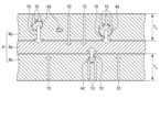
- FIG. 2 is a schematic cross-sectional view taken along line II-II of the electrode shown in FIG.
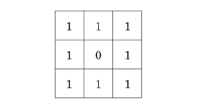
- FIG. 3 is a conceptual diagram showing an example of a part of a binarized state of a cross-sectional observation image of an electrode according to an embodiment, observed by a scanning electron microscope.
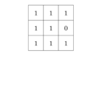
- FIG. 4 is a conceptual diagram showing another example of a part of a state in which a cross-sectional observation image of an electrode according to the embodiment is binarized using a scanning electron microscope.
- FIG. 5 is a conceptual diagram showing another example of a part of a state in which a cross-sectional observation image of an electrode according to the embodiment is binarized using a scanning electron microscope.
- FIG. 1 is a plan view that illustrates an example of an electrode according to an embodiment.
- FIG. 2 is a schematic cross-sectional view taken along line II-II of the electrode shown in FIG.
- FIG. 3 is
- FIG. 6 is a graph showing the radial distribution function by Fourier transform of the extended x-ray absorption fine structure spectrum at the Al K-edge for the surface of an example electrode according to an embodiment.
- FIG. 7 is a cross section of an example of a battery according to the embodiment cut in the thickness direction.
- FIG. 8 is an enlarged cross-sectional view of a portion E in FIG.
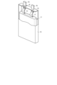
- FIG. 9 is a partially cutaway perspective view of a battery according to another example of the embodiment.
- FIG. 10 is an exploded perspective view of an example battery pack according to an embodiment.
- FIG. 11 is a block diagram showing an electric circuit of the battery pack shown in FIG.
- coating active material particles with an aluminum oxide compound has the effect of improving resistance increase.
- aluminum oxide compounds are insulating, the inclusion of aluminum oxide compounds increases the initial resistance. Therefore, coating with aluminum oxide compounds has the disadvantage of reducing charge/discharge rate performance.
- each figure is a schematic diagram intended to facilitate the explanation and understanding of the embodiment, and the shape, dimensions, ratios, etc. may differ from those of the actual device, but these can be appropriately modified in design by taking into consideration the following explanation and publicly known technology.
- an electrode comprising an active material-containing layer containing an active material and an aluminum oxide compound.
- the active material includes a titanium-containing oxide.
- the aluminum oxide compound is present on the surface of the titanium-containing oxide.
- the titanium-containing oxide has a form including a primary particle and an aggregate containing a plurality of the primary particles.
- the active material-containing layer includes a peak A appearing in a range of 1.1 ⁇ to 1.5 ⁇ and a peak B appearing in a range of 2.8 ⁇ to 3.2 ⁇ in a radial distribution function obtained by Fourier transformation of a broadband X-ray absorption fine structure spectrum at the Al K absorption edge.
- the ratio I A /I B of the peak intensity I A of peak A to the peak intensity I B of peak B is 3.5 to 9.
- the least square circle diameter D g of the aggregate is 1/20 or more and less than 1/2 of the thickness T e of the active material-containing layer.
- the electrode according to the embodiment may be an electrode for a battery.
- batteries that may include the electrode according to the embodiment include secondary batteries such as lithium ion secondary batteries.
- Secondary batteries include non-aqueous electrolyte secondary batteries that include a non-aqueous electrolyte.
- the electrode may be, for example, a negative electrode for a battery.
- Secondary batteries with negative electrodes containing titanium-containing oxides have excellent cycle life and storage performance, and are capable of charging and discharging at high currents and under low-temperature conditions.
- the inventors of the present invention have conducted extensive research to solve this problem related to non-aqueous electrolyte batteries equipped with a negative electrode containing a titanium-containing oxide, and as a result have discovered the electrode according to the first embodiment. Specifically, they have discovered that the presence of a specific aluminum oxide compound on the surface of the titanium-containing oxide can suppress the increase in resistance due to surface side reactions, and that the aggregation of some of the particles can suppress the increase in resistance while improving the rate performance and energy density.
- the electrode according to the first embodiment is an electrode containing a titanium-containing oxide as an electrode active material, and has an aluminum oxide compound on the surface of titanium-containing oxide particles.
- the titanium-containing oxide coated with the aluminum oxide compound exists in two states: primary particles and aggregates formed by agglomeration of the primary particles.
- the radial distribution function obtained by Fourier transformation of the extended X-ray absorption fine structure (EXAFS) spectrum at the K-edge of Al on the electrode surface includes a peak A appearing in the range of 1.1 ⁇ to 1.5 ⁇ and a peak B appearing in the range of 2.8 ⁇ to 3.2 ⁇ .
- the ratio I A /I B of the peak intensity I A of peak A to the peak intensity I B of peak B is 3.5 to 9.
- the aggregate has a size such that the least square circle diameter D g is 1/20 or more and less than 1/2 of the thickness T e of the active material-containing layer.
- the primary particle diameter of the active material particles is made small, for example 1 ⁇ m or less, the specific surface area increases, and the lithium ion acceptance performance of the active material itself improves. However, as the primary particle diameter becomes smaller, the proportion of active sites on the active material surface increases. This increases side reactions between the active material and electrolytes, etc., and increases the rise in electrical resistance during storage.
- the aluminum oxide compound is present on the active material surface in a specific state, which can suppress side reactions with the electrolyte solution, etc.
- the radial distribution function of the EXAFS spectrum of Al obtained by Fourier transformation includes peak A in the range of 1.1 ⁇ to 1.5 ⁇ and peak B in the range of 2.8 ⁇ to 3.2 ⁇ , and the peak intensity ratio I A /I B of these peaks is 3.5 to 9, it is determined that the aluminum oxide compound is present on the active material surface in a state effective for suppressing the above-mentioned side reactions. It is considered that at least a part of the aluminum oxide compound condenses with functional groups that can become active sites present on the active material surface, suppressing the side reactions.
- part of the titanium-containing oxide contained in the electrode exists as an aggregate formed by the aggregation of primary particles.
- an aggregate of titanium-containing oxide can be formed by a reaction between an alcohol contained in a solution of an aluminum alkoxide compound that can function as an aluminum oxide compound source and a binder that the electrode may contain together with the active material.
- the titanium-containing oxide exhibits electrical conductivity when lithium ions are inserted, for example, when an electrode containing a titanium-containing oxide as a negative electrode active material is in a charged state. Therefore, in the electrode having the above configuration, when a large current is passed for a short time, the current flows concentrating in the aggregates with small gaps between the grain boundaries. This makes it possible to reduce the electrical resistance (IR drop) during short-term use.
- the mixture of primary particles and aggregates of titanium-containing oxide in the active material-containing layer enables the active material to be packed closely together. This electrode therefore has excellent energy density.
- the least square circle diameter Dg of the aggregate is 1/20 or more and less than 1/2 of the thickness T e of the active material containing layer (1/20 ⁇ D g /T e ⁇ 1/2).
- the least square circle diameter Dg of the aggregate can be, for example, in the range of 4 ⁇ m or more and 20 ⁇ m or less.
- the electrode includes an active material-containing layer (electrode mixture layer) and may further include a current collector.
- the active material-containing layer may be formed, for example, on one side or both sides of a strip-shaped current collector.
- the active material-containing layer may include an active material, an aluminum oxide compound, and optionally a conductive agent and a binder.
- the active material includes, for example, a titanium-containing oxide having an average primary particle size of 600 nm or more and 1 ⁇ m or less.
- the titanium-containing oxide preferably includes a lithium titanium composite oxide.
- An electrode including a titanium-containing oxide such as a lithium titanium composite oxide can exhibit a Li absorption potential of 0.4 V (vs. Li/Li + ) or more relative to the oxidation-reduction potential of lithium, and therefore can prevent deposition of metallic lithium on the electrode surface when input and output at a large current are repeated.
- the titanium-containing oxide particularly preferably includes a lithium titanium composite oxide having a spinel crystal structure.
- a specific example of such a spinel-type lithium titanium composite oxide is lithium titanate having a spinel structure, which is represented by Li 4+a Ti 5 O 12 , where the value of the subscript a changes within the range of 0 ⁇ a ⁇ 3 upon charging and discharging.
- the titanium-containing oxide is coated with an aluminum oxide compound.
- the titanium-containing oxide coated with the aluminum oxide compound exists in the active material-containing layer in two states: primary particles and aggregates formed by agglomeration of the primary particles.
- the aggregate here refers to a collection of active material in which there is no "0" inside when the active material (titanium-containing oxide) and voids are binarized in an image obtained by observing the cross section of the active material-containing layer with a scanning electron microscope (SEM), and aluminum elements are confirmed inside by energy dispersive X-ray spectroscopy (EDX) in an image obtained by observing with a transmission electron microscope (TEM).
- SEM scanning electron microscope
- EDX energy dispersive X-ray spectroscopy
- TEM transmission electron microscope
- the "aggregate” according to each embodiment is distinguished from secondary particles having internal voids.
- the "aggregate” according to each embodiment is also distinguished from secondary particles that were formed as secondary particles before being coated with the aluminum oxide compound.
- the active material particles in the center of the aggregate are coated with the aluminum oxide compound, but the active material particles in the center of the secondary particles as exemplified here are not coated with the aluminum oxide compound.
- the presence of the aluminum oxide compound not only on the outer periphery of the aggregate but also on the surface of the primary particles located inside the aggregate can suppress side reactions between the electrolyte that gradually penetrates over time and the active material.
- it is desirable that all of the secondary particles of the titanium-containing oxide contained in the active material-containing layer are aggregates as described above. SEM observation will be described in detail later.
- the aggregate may further contain an aluminum oxide compound and a binder.
- the active material may contain an active material other than the titanium-containing oxide.
- the active material containing the titanium-containing oxide described above may be called the “first active material”, and the other active material may be called the “second active material”.
- the active material further contains a second active material in addition to the first active material, it is desirable to use an active material that can exhibit a Li absorption potential of 0.4 V (vs. Li/Li + ) or more as the second active material.
- the mass ratio of the second active material to the first active material is preferably 5 mass% or more and 40 mass% or less, more preferably 10 mass% or more and 30 mass% or less.
- the aluminum oxide compound can have the effect of coating the surface of the active material containing at least a titanium-containing oxide and suppressing an increase in resistance.
- the aluminum oxide compound is, for example, one derived from an aluminum oxide compound.
- the conductive agent can improve current collection performance and suppress the contact resistance between the active material and the current collector.
- conductive agents include carbonaceous materials such as acetylene black, carbon black, graphite, carbon nanofibers, and carbon nanotubes. These carbonaceous materials may be used alone or in combination.
- the binder can have the function of binding the active material, conductive agent, and current collector.
- binders include polytetrafluoroethylene (PTFE), polyvinylidene fluoride (PVdF), fluorine-based rubber, styrene butadiene rubber, acrylic resin and its copolymer, polyacrylic acid, and polyacrylonitrile.
- the compounding ratios of the active material, conductive agent, and binder are preferably within the ranges of 70% by mass or more and 97.5% by mass or less for the active material, 2% by mass or more and 20% by mass or less for the conductive agent, and 0.5% by mass or more and 10% by mass or less for the binder.
- the amount of conductive agent 2% by mass or more the current collection performance of the active material-containing layer is improved, and excellent high-current performance and low-temperature performance can be expected.
- the amount of binder 0.5% by mass or more sufficient adhesion between the active material-containing layer and the current collector is achieved, and excellent life performance can be expected.
- the conductive agent and binder are each preferably 20% by mass or less, and more preferably 10% by mass or less.
- the ratio S G /S E of the cross-sectional area S G of the aggregates occupying the cross section to the cross-sectional area S E of the active material-containing layer is 1/200 or more and 1/4 or less.
- the proportion of aggregates in the active material remains at a proportion such that 1/200 or more and 1/4 or less of the total cross-sectional area of the aggregates in the cross section of the active material-containing layer is 1/200 or more and 1/4 or less, the primary particles of the active material can enter the gaps between the aggregates. Therefore, the above-mentioned electrode has excellent energy density.
- the current collector is preferably formed from an aluminum foil or an aluminum alloy foil containing elements such as Mg, Ti, Zn, Mn, Fe, Cu and Si.
- the thickness of the current collector is preferably 20 ⁇ m or less, more preferably 15 ⁇ m or less.
- FIG. 1 is a partially cutaway plan view that shows a schematic example of such an electrode.
- FIG. 2 is a cross-sectional view taken along line II-II in FIG. 1.
- an example of a negative electrode is shown as an example of an electrode.
- the negative electrode 4 shown in Figs. 1 and 2 comprises a negative electrode current collector 4a and a negative electrode active material-containing layer 4b provided on the surface of the negative electrode current collector 4a.
- the negative electrode active material-containing layer 4b is supported on the main surface of the negative electrode current collector 4a.
- the negative electrode active material-containing layer 4b may be provided on both the front and back main surfaces of the negative electrode current collector 4a as shown in Fig. 2.
- the negative electrode active material-containing layer 4b may be provided on only one main surface of the negative electrode current collector 4a.
- the negative electrode current collector 4a also includes a portion on its surface where the negative electrode active material-containing layer 4b is not provided. This portion functions, for example, as a negative electrode current collector tab 4c.
- the negative electrode current collector tab 4c is a narrow portion that is narrower than the negative electrode active material-containing layer 4b.
- the width of the negative electrode current collector tab 4c may be narrower than the width of the negative electrode active material-containing layer 4b in this way, or may be the same as the width of the negative electrode active material-containing layer 4b.
- a separate conductive member may be electrically connected to the negative electrode 4 and used as an electrode current collector tab (negative electrode current collector tab).
- the negative electrode active material-containing layer 4b contains a negative electrode active material containing a titanium-containing oxide.
- the negative electrode active material is contained in the negative electrode active material-containing layer 4b in the form of primary particles and in the form of aggregates 4d formed by aggregation of the primary particles. In FIG. 2, the depiction of each primary particle forming the aggregates 4d is omitted.
- the negative electrode active material-containing layer 4b can further contain a conductive agent and a binder. In FIG.
- each member (other active material such as titanium-containing oxide in the form of primary particles, conductive agent, binder) other than the aggregates 4d contained in the negative electrode active material-containing layer 4b is omitted, and the part of the negative electrode active material-containing layer 4b other than the aggregates 4d is shown diagrammatically.
- the average least square circle diameter D g (not shown) of the aggregates 4d contained in the negative electrode active material containing layer 4b is 1/20 or more and less than 1/2 of the thickness T e of the negative electrode active material containing layer 4b.
- the active material particles that make up the aggregate 4d are close to each other, and the grain boundaries between them are not separated. Therefore, the current 10 flows more easily through the aggregate 4d than through the remaining part of the negative electrode active material-containing layer 4b. Therefore, when a large current is passed through for a short period of time, the current 10 flows concentratedly through the aggregate 4d.
- Such an electrode can be manufactured as follows.
- an active material containing a titanium-containing oxide is prepared.
- the titanium-containing oxide can be synthesized, for example, by a solid-phase method.
- the titanium-containing oxide can also be synthesized by a wet synthesis method such as a sol-gel method or a hydrothermal method.
- a Ti source and a Li source according to the target composition.
- These raw materials can be compounds such as oxides or salts.
- Lithium hydroxide, lithium oxide, lithium carbonate, etc. can be used as the Li source.
- the prepared raw materials are mixed in an appropriate stoichiometric ratio to obtain a mixture.
- a spinel-type lithium titanium composite oxide represented by the composition formula Li 4 Ti 5 O 12 titanium oxide TiO 2 and lithium carbonate Li 2 CO 3 can be mixed so that the molar ratio of Li:Ti in the mixture is 4:5.
- Li When mixing the raw materials, Li may be mixed in an amount greater than the prescribed amount. In particular, Li may be added in an amount greater than the prescribed amount, as there is concern that it may be lost during heat treatment.
- the raw materials are dissolved in pure water, and the resulting solution is dried while being stirred to obtain the calcined precursor. Drying methods include spray drying, granulation drying, freeze drying, or a combination of these.
- the mixture or calcined precursor obtained by the previous mixing is heat-treated at a temperature of 750°C to 1000°C for a time period of 30 minutes to 24 hours.
- 750°C sufficient crystallization is difficult to obtain.
- 1000°C grain growth proceeds too much, resulting in coarse particles, which is undesirable.
- the heat treatment time is less than 30 minutes, sufficient crystallization is difficult to obtain.
- the heat treatment time is longer than 24 hours, grain growth proceeds too much, resulting in coarse particles, which is undesirable.
- Calcination may be performed in air. Calcination may also be performed in an oxygen, nitrogen, or argon atmosphere.
- Titanium-containing oxide can be obtained by such heat treatment.
- Pre-calcination may also be performed before the main calcination. Pre-calcination is performed at a temperature of 450°C to 700°C for a period of 5 hours to 24 hours.
- the sample obtained by the firing process can be pulverized to break down the agglomerates (secondary particles) into primary particles.
- a mortar, ball mill, sand mill, vibration ball mill, planetary ball mill, bead mill, jet mill, counter jet mill, swirling airflow type jet mill, etc. can be used as the pulverization method.
- wet pulverization in the presence of a liquid pulverization aid such as water, ethanol, ethylene glycol, benzene, or hexane can also be used.
- the pulverization aid is effective in improving the pulverization efficiency and increasing the amount of fine powder produced.
- a more preferred method is a ball mill using zirconia balls as the media, and wet pulverization with the addition of a liquid pulverization aid is preferred. Furthermore, organic substances such as polyols that improve pulverization efficiency may be added as pulverization aids.
- the type of polyol is not particularly limited, but pentaerythritol, triethylolethane, trimethylolpropane, etc. can be used alone or in combination.
- re-firing may be performed after the grinding treatment.
- the average crystallite size of the titanium-containing oxide particles can be controlled by adjusting the firing conditions.
- Re-firing may be performed in the air, or in an inert atmosphere using oxygen, nitrogen, argon, or the like.
- Re-firing may be performed at a temperature of 250°C to 900°C for about 1 minute to 10 hours.
- 900°C or less sintering between powder particles can be avoided.
- impurities (organic substances) adhering during wet grinding can be removed.
- re-firing is performed at a temperature of 400°C to 700°C for 10 minutes to 3 hours. It is also preferable to wash with an aqueous solvent before re-firing.
- classification can be performed as necessary to obtain primary particles with a specific particle size.
- an electrode slurry is prepared using the active material containing the titanium-containing oxide prepared as described above.
- the electrode slurry is prepared using the second active material together with the active material containing the titanium-containing oxide (first active material).
- the active material and the conductive agent are mixed to obtain a mixture, and then a binder, an aluminum alkoxide compound, and a solvent are added, followed by kneading and dispersion treatment to prepare a slurry.
- the solvent for example, N-methylpyrrolidone (NMP) can be used.
- Aluminum alkoxide is a type of metal alkoxide.
- Metal alkoxide is a material represented by M(OR) n, which is a structure in which an alkoxy group is coordinated around a metal element (M: Ti, Zr, Al, Si, etc.). It reacts with a Lewis base to synthesize a material with a MOM bond as the main chain.
- the aluminum alkoxide compound added to the electrode slurry is preferably one in which at least two alkoxy groups are coordinated, and the other substituents have a chain structure or a ring structure functional group composed of C, O, N, etc. Furthermore, it is more preferable to have a chelate structure.
- an alkoxide compound with a substituent with three or more carbon atoms it is also preferable to use an alkoxide compound with a substituent with three or more carbon atoms.
- di-2-butoxyaluminum ethyl acetoacetate Al(C 4 H 9 O) 2 (C 6 H 9 O 3 )
- aluminum tri-2-butoxide Al(OC 4 H 9 ) 3
- di-2-butoxyaluminum acetylacetate Al(C 4 H 9 O) 2 (C 5 H 7 O 2 )
- aluminum tri-secondary butoxide Al(O-sec-C 4 H 9 ) 3
- the above-mentioned state in which the peak intensity ratio I A /I B value is 3.5 or more and 9 or less in the radial distribution function by FT-EXAFS of Al is easily obtained. That is, the addition of these aluminum alkoxide compounds is effective in suppressing side reactions on the electrode.
- Other aluminum alkoxide compounds having a substituent with less than 4 carbon atoms include, for example, aluminum isopropoxide (Al(Oi-Pr) 3 ).
- the aluminum alkoxide compound to be added may be one type or two or more types.
- Aluminum alkoxide compounds are used in solvents to maintain their structure during storage.
- solvents include alcohols such as ethanol, propanol, and butanol.
- Aluminum alkoxides also release alcohol through hydrolysis. Therefore, even when an aluminum alkoxide reagent is used that uses a solvent that does not contain alcohol, alcohol is introduced into the system.
- an aggregate containing an active material is formed by the reaction of the alcohol with the binder.
- the aggregate may contain the binder and, for example, an aluminum oxide compound formed by the release of organic components of the aluminum alkoxide.
- the amount and size of the aggregates formed can be controlled by adjusting the content ratio of each component (active material, conductive agent, binder) contained in the electrode and the type and amount of aluminum alkoxide compound added.
- the size of the aggregates can be controlled by the timing of adding the aluminum alkoxide compound.
- the aluminum alkoxide compound may be added before kneading, or the aluminum alkoxide compound may be added after kneading and dispersion.
- the slurry prepared as described above is applied to one or both sides of a current collector, and the coating is then dried. In this way, an electrode mixture layer (active material-containing layer) can be formed. Thereafter, the electrode mixture layer is pressed. In this way, the electrode according to the first embodiment can be obtained.
- Electrode Measurement> Various measurement methods for the electrode are described below. Specifically, a method for confirming that the electrode contains a titanium-containing oxide, a method for observing the cross section of the electrode using a scanning electron microscope, and a method for measuring the extended X-ray absorption fine structure (EXAFS) at the Al K absorption edge and performing a Fourier transform on the resulting EXAFS spectrum to obtain a radial distribution function are described below.
- EXAFS extended X-ray absorption fine structure
- the electrode to be measured is incorporated in a battery, remove the electrode as a measurement sample from the battery as follows: Discharge the battery, disassemble it in a glove box with an inert atmosphere such as argon, and remove the electrode. Wash the electrode with diethyl carbonate and then vacuum dry it. This is how the measurement sample is obtained.
- the active material contained in the electrode can be identified as follows, and the presence or absence of a titanium-containing oxide can be confirmed.
- the electrodes After cleaning and drying the electrodes removed from the battery as described above, attach the resulting electrodes to a glass sample plate. At this time, care should be taken to prevent the electrodes from peeling off or floating using double-sided tape or similar. If necessary, the electrodes may be cut to a size appropriate for attaching to the glass sample plate. In addition, a Si standard sample may be added to the electrodes to correct the peak position.
- the glass plate with the electrodes attached is placed in a powder X-ray diffraction (XRD) device and a diffraction pattern is obtained using Cu-K ⁇ radiation.
- XRD powder X-ray diffraction
- X-ray source Cu target Output: 45 kV, 200 mA Soller slit: 5° for both incidence and reception Step width: 0.02 deg Scan speed: 20 deg/min Semiconductor detector: D/teX Ultra 250 Sample plate holder: Flat glass sample plate holder (thickness 0.5 mm) Measurement range: 5° ⁇ 2 ⁇ 90°.
- measurements should be performed using standard Si powder for powder X-ray diffraction to obtain measurement results equivalent to those obtained above, and conditions should be found under which the peak intensity and peak top position are equivalent to those obtained by the above equipment, and the sample should be measured under those conditions.
- the active material being measured contains a spinel-type lithium titanium composite oxide, it can be confirmed by X-ray diffraction measurement that an X-ray diffraction pattern belonging to the space group Fd-3m is obtained.
- the sample containing the active material is observed using a scanning electron microscope (SEM). Even during SEM observation, it is advisable to prevent the sample from coming into contact with the air and to conduct the observation in an inert atmosphere such as argon or nitrogen.
- SEM scanning electron microscope
- EDX energy dispersive X-ray spectroscopy
- the active material-containing layer is separated from the current collector using, for example, a spatula to obtain a powdered electrode composite sample containing the active material.
- the collected powdered sample is washed with acetone and dried.
- the obtained powder is dissolved in hydrochloric acid, the conductive agent is removed by filtration, and then the measurement sample is prepared by diluting with ion-exchanged water.
- the metal content ratio in the measurement sample is calculated using inductively coupled plasma atomic emission spectroscopy (ICP-AES).
- the mass ratio is estimated from the content ratio of elements specific to each active material.
- the ratio of specific elements to the mass of the active material is determined from the composition of the constituent elements determined by energy dispersive X-ray spectroscopy.
- the active material contained in the electrode can be identified.
- active materials containing titanium-containing oxides those in the form of primary particles and those in the form of aggregates are distinguished as follows. This also makes it possible to distinguish between secondary particles with internal voids and aggregates.
- a binarization process is performed on the active material and voids in the cross-sectional SEM image of the electrode. When binarized, a cluster of active material that does not have a "0" inside is considered to be an aggregate.
- a cluster of active material that has zeros on the periphery is also considered to be an aggregate, as long as there are no zeros inside.
- Figures 3 to 5 show conceptual diagrams showing clusters of binarized active material.
- aggregates can be, for example, aggregates of electrode members that do not form aggregates, or secondary particles with internal voids.
- secondary particles that do not have aluminum oxide compounds on the surface of primary particles inside the secondary particles and aggregates are distinguished as follows.
- the cross section of the electrode obtained as described above is observed with a transmission electron microscope (TEM-EDX) equipped with an energy dispersive X-ray analyzer. The magnification of the TEM observation is 3 million times.
- clusters of active material that are confirmed to have no "0" inside in the binarized SEM image as described above in the cross-sectional TEM image of the electrode clusters in which the presence of Al inside can be confirmed by EDX are regarded as aggregates.
- Clusters that are confirmed to have no "0" inside but also no Al inside can be judged to be secondary particles without voids, for example, secondary particles formed from primary particles that were not coated with aluminum oxide before secondary particle formation.
- the cross-sectional area S E of the active material-containing layer (including the cross-sectional area of the aggregate), the total cross-sectional area S G of the aggregate, the least squares circle diameter D g of each aggregate, and the thickness T e of the active material-containing layer are measured.
- the ratios S G /S E and D g /T e are calculated using the results obtained.
- Extended X-ray absorption fine structure measurements and Fourier transforms can be performed as follows.
- the sample After removing the electrodes from the battery and washing and drying them in an inert atmosphere, the sample is introduced into the vacuum chamber of the measuring instrument. The sample is irradiated with X-rays and the amount of absorption is measured to obtain an X-ray absorption fine structure (XAFS) spectrum (electron yield method).
- XAFS X-ray absorption fine structure
- the structure near the absorption edge is called XANES (X-ray Absorption Near Edge Structure)
- EXAFS Extended X-ray Absorption Fine Structure
- Information on the valence and structure of the target atom can be obtained from XANES, and in EXAFS analysis, information on the local structure of the sample (atomic species, valence, and distance around the target atom) can be obtained by Fourier transform of the real spectrum (FT-EXAFS; equivalent to the radial distribution function).
- FT-EXAFS Fourier transform of the real spectrum
- the obtained spectral data is normalized around the absorption edge to derive the XANES spectrum.
- the EXAFS oscillation ( ⁇ (k)) obtained by EXAFS analysis is expressed by the following equation based on the plane wave single scattering theory.
- the subscript i is the number of the coordination sphere
- S 0 2 is the attenuation factor
- N i is the number of atoms in the i-th coordination sphere
- F i (k i ) is the backscattering intensity
- k i is the wave number
- r i is the bond length
- ⁇ i is the Debye-Waller (DW) factor
- ⁇ i (k i ) is the phase shift.
- the EXAFS function (k 3 ⁇ (k)) is obtained by weighting the EXAFS vibration ( ⁇ (k)) with k 3 to enhance the vibration on the high wavenumber side. By comparing the amplitude of the EXAFS function (k 3 ⁇ (k)), the number of coordinated atoms of the measured atom can be estimated.
- a radial distribution function is obtained by Fourier transforming an EXAFS spectrum in the region (corresponding to the EXAFS region) of the EXAFS function (k 3 ⁇ (k)) where 2.5 ⁇ k ⁇ 7.
- Athena (Non-Patent Document 1) can be used as the analysis software.
- the spectrum obtained for the electrode is shown by the solid line 49, and the spectrum obtained for the aluminum alkoxide additive alone used to prepare the electrode is shown by the dashed line 90.
- the shapes of the two spectra are similar. Therefore, it can be seen that the added aluminum alkoxide is present on the active material on the electrode surface in a form that maintains the Al-O structure and Al-O-C structure, and has not changed into other components such as alumina.
- Peak A which is in the range of 1.1 ⁇ to 1.5 ⁇ , can be attributed to Al-O bonds.
- Peak B which is in the range of 2.8 ⁇ to 3.2 ⁇ , can be attributed to Al-O-C bonds. In electrodes in which the Al-O-C bonds of simple aluminum alkoxides remain intact on the active material surface, side reactions on the active material surface are suppressed.
- the electrode according to the first embodiment includes an active material and an aluminum oxide compound in an active material-containing layer.
- the active material includes a titanium-containing oxide in the form of primary particles and aggregates thereof.
- the aluminum oxide compound coats the titanium-containing oxide.
- the peak intensities I A and I B of a peak A appearing in the range of 1.1 ⁇ to 1.5 ⁇ and a peak B appearing in the range of 2.8 ⁇ to 3.2 ⁇ satisfy the relationship of 3.5 ⁇ I A /I B ⁇ 9.
- the least square circle diameter D g of the aggregate is 1/20 or more and less than 1/2 of the thickness T e of the active material-containing layer.
- a battery includes a positive electrode, a negative electrode, and an electrolyte. At least one of the positive electrode and the negative electrode includes the electrode according to the first embodiment. In a preferred embodiment of the battery, the negative electrode includes the electrode according to the first embodiment.
- the battery may further include a separator disposed between the positive electrode and the negative electrode.
- the positive electrode, the negative electrode, and the separator may constitute an electrode group.
- the electrolyte may be retained in the electrode group.
- the battery may further include an exterior member that contains the electrode group and the electrolyte.
- the battery may further include a positive electrode terminal electrically connected to the positive electrode and a negative electrode terminal electrically connected to the negative electrode. At least a portion of the positive electrode terminal and at least a portion of the negative electrode terminal may extend outside the exterior member.
- Such a battery may be, for example, a lithium ion secondary battery.
- the battery may also include, for example, a non-aqueous electrolyte battery that contains a non-aqueous electrolyte as the electrolyte.
- the negative electrode, positive electrode, electrolyte, separator, exterior member, positive electrode terminal, and negative electrode terminal are described in detail below.
- the negative electrode includes a negative electrode current collector and a negative electrode active material-containing layer (negative electrode mixture layer) supported on one side or both sides of the negative electrode current collector and containing a negative electrode active material, a conductive agent, and a binder.
- the negative electrode may be the electrode according to the first embodiment.
- the negative electrode current collector, the negative electrode active material, and the negative electrode active material-containing layer of the negative electrode correspond to the current collector, the active material, and the active material-containing layer of the electrode according to the first embodiment, respectively.
- the electrode according to the first embodiment has been described in detail above, so a description of the negative electrode here will be omitted.
- the positive electrode includes a positive electrode current collector and a positive electrode active material-containing layer (positive electrode mixture layer) supported on one side or both sides of the positive electrode current collector and containing a positive electrode active material, a conductive agent, and a binder.
- the battery according to the second embodiment may include the electrode according to the first embodiment as a positive electrode.
- the battery may include a positive electrode having a different configuration from the electrode according to the first embodiment.
- a description is given of a positive electrode having a different configuration from the electrode according to the first embodiment.
- lithium-containing cobalt oxide e.g., LiCoO 2
- manganese dioxide lithium manganese composite oxide
- lithium manganese composite oxide e.g., LiMn 2 O 4 , LiMnO 2
- lithium-containing nickel oxide e.g., LiNiO 2
- lithium-containing nickel cobalt oxide e.g., LiNi 0.8 Co 0.2 O 2
- lithium-containing iron oxide vanadium oxide containing lithium
- chalcogen compounds such as titanium disulfide and molybdenum disulfide
- the type of positive electrode active material used can be one or more types.
- binders examples include polytetrafluoroethylene (PTFE), polyvinylidene fluoride (PVdF), fluorine-based rubber, styrene-butadiene rubber (SBR), carboxymethyl cellulose (CMC), polyimide, polyamide, etc.
- PTFE polytetrafluoroethylene
- PVdF polyvinylidene fluoride
- SBR styrene-butadiene rubber
- CMC carboxymethyl cellulose
- polyimide polyimide
- polyamide polyamide
- Conductive agents include, for example, carbon black such as acetylene black and ketjen black, graphite, carbon fiber, carbon nanotubes, fullerenes, etc.
- the conductive agent may be of one type or two or more types.
- the mixing ratio of the positive electrode active material, conductive agent, and binder in the positive electrode active material-containing layer is preferably 80% by mass or more and 95% by mass or less of the positive electrode active material, 3% by mass or more and 18% by mass or less of the conductive agent, and 2% by mass or more and 17% by mass or less of the binder.
- the current collector is preferably an aluminum foil or an aluminum alloy foil, with an average crystal grain size of 50 ⁇ m or less, more preferably 30 ⁇ m or less, and even more preferably 5 ⁇ m or less.
- a current collector made of an aluminum foil or an aluminum alloy foil with such an average crystal grain size can dramatically increase the strength, making it possible to densify the positive electrode with high pressing pressure, and thus increasing the battery capacity.
- Aluminum foil or aluminum alloy foil with an average crystal grain size of 50 ⁇ m or less is affected in complex ways by many factors, including material composition, impurities, processing conditions, heat treatment history, and annealing heating conditions, and the above (diameter) is adjusted during the manufacturing process by combining the above factors.
- the thickness of the current collector is preferably 20 ⁇ m or less, and more preferably 15 ⁇ m or less.
- the purity of the aluminum foil is preferably 99% or more.
- As the aluminum alloy an alloy containing elements such as magnesium, zinc, and silicon is preferable.
- the content of transition metals such as iron, copper, nickel, and chromium is preferably 1% or less.
- the positive electrode is produced, for example, by suspending the positive electrode active material, conductive agent, and binder in a suitable solvent, applying the resulting slurry to a current collector and drying it to produce a positive electrode active material-containing layer, which is then pressed.
- the positive electrode active material, conductive agent, and binder may be formed into pellets to be used as the positive electrode active material-containing layer.
- the positive electrode active material-containing layer preferably has a porosity of 20% or more and 50% or less.
- a positive electrode having a positive electrode active material-containing layer with such a porosity has high density and excellent affinity with the electrolyte.
- a more preferable porosity is 25% or more and 40% or less.
- the density of the positive electrode active material-containing layer is preferably 2.5 g/cm 3 or more.
- Electrolyte examples include a liquid nonaqueous electrolyte prepared by dissolving an electrolyte salt (solute) in a nonaqueous solvent, and a gel-like nonaqueous electrolyte prepared by combining a liquid nonaqueous electrolyte with a polymer material.
- a liquid nonaqueous electrolyte prepared by dissolving an electrolyte salt (solute) in a nonaqueous solvent
- a gel-like nonaqueous electrolyte prepared by combining a liquid nonaqueous electrolyte with a polymer material.
- electrolyte salt examples include lithium salts such as lithium perchlorate (LiClO 4 ), lithium hexafluorophosphate (LiPF 6 ), lithium tetrafluoroborate (LiBF 4 ), lithium hexafluoroarsenic (LiAsF 6 ), lithium difluorophosphate (LiPO 2 F 2 ), lithium trifluoromethanesulfonate (LiCF 3 SO 3 ), and lithium bistrifluoromethylsulfonylimide [LiN(CF 3 SO 2 ) 2 ].
- lithium salts such as lithium perchlorate (LiClO 4 ), lithium hexafluorophosphate (LiPF 6 ), lithium tetrafluoroborate (LiBF 4 ), lithium hexafluoroarsenic (LiAsF 6 ), lithium difluorophosphate (LiPO 2 F 2 ), lithium trifluoromethanesulfonate (LiCF 3 SO 3
- the electrolyte salt is preferably dissolved in the non-aqueous solvent in a range of 0.5 mol/L to 2.5 mol/L.
- non-aqueous solvents examples include cyclic carbonates such as ethylene carbonate (EC), propylene carbonate (PC), and vinylene carbonate (VC); chain carbonates such as dimethyl carbonate (DMC), ethyl methyl carbonate (EMC), and diethyl carbonate (DEC); and tetrahydrofuran.
- cyclic carbonates such as ethylene carbonate (EC), propylene carbonate (PC), and vinylene carbonate (VC); chain carbonates such as dimethyl carbonate (DMC), ethyl methyl carbonate (EMC), and diethyl carbonate (DEC); and tetrahydrofuran.
- organic solvents examples include cyclic ethers such as tetrahydrofuran (THF) and 2-methyl tetrahydrofuran (2MeTHF); chain ethers such as dimethoxyethane (DME); cyclic esters such as ⁇ -butyrolactone (BL); chain esters such as methyl acetate, ethyl acetate, methyl propionate, and ethyl propionate; acetonitrile (AN); and sulfolane (SL).
- cyclic ethers such as tetrahydrofuran (THF) and 2-methyl tetrahydrofuran (2MeTHF)
- chain ethers such as dimethoxyethane (DME)
- cyclic esters such as ⁇ -butyrolactone (BL)
- chain esters such as methyl acetate, ethyl acetate, methyl propionate, and ethyl propionate
- AN acet
- polymer materials used for the gel-like non-aqueous electrolyte include polyvinylidene fluoride (PVdF), polyacrylonitrile (PAN), and polyethylene oxide (PEO).
- PVdF polyvinylidene fluoride
- PAN polyacrylonitrile
- PEO polyethylene oxide
- the separator is not particularly limited as long as it has insulating properties, and a porous film or nonwoven fabric made of a polymer such as polyolefin, cellulose, polyethylene terephthalate, polyimide, polyamideimide, polyvinylidene fluoride, and vinylon can be used. Inorganic oxides such as alumina, titania, and zirconia can also be used.
- the separator may be made of one type of material, or two or more types may be used in combination. The separator may also be integrated with the electrodes.
- Exterior member may be formed from a laminate film or may be a metal container. When a metal container is used, the lid may be integrated with the container or may be a separate member.
- the thickness of the metal container is preferably 0.5 mm or less, more preferably 0.2 mm or less.
- the shape of the exterior member may be flat, rectangular, cylindrical, coin, button, sheet, laminated, etc.
- the exterior member may be for a small battery mounted on a portable electronic device or for a large battery mounted on a two- or four-wheeled vehicle.
- the thickness of the laminate film exterior component is desirably 0.2 mm or less.
- An example of a laminate film is a multilayer film containing a resin film and a metal layer disposed between the resin films.
- the metal layer is preferably aluminum foil or aluminum alloy foil to reduce weight.
- the resin film can be made of polymeric materials such as polypropylene (PP), polyethylene (PE), nylon, and polyethylene terephthalate (PET).
- PP polypropylene
- PE polyethylene
- PET polyethylene terephthalate
- the laminate film can be sealed by heat fusion and molded into the shape of the exterior component.
- the metal container is made of aluminum or an aluminum alloy.
- the aluminum alloy is preferably an alloy containing elements such as magnesium, zinc, or silicon.
- transition metals such as iron, copper, nickel, and chromium
- the metal container made of aluminum or an aluminum alloy prefferably has an average crystal grain size of 50 ⁇ m or less, more preferably 30 ⁇ m or less, and even more preferably 5 ⁇ m or less.
- the strength of the metal container made of aluminum or an aluminum alloy can be dramatically increased, and the container can be made even thinner.
- the flat battery shown in Figure 7 includes a flat wound electrode group 1, an exterior member 2, a positive electrode terminal 7, a negative electrode terminal 6, and an electrolyte (not shown).
- the exterior member 2 is a bag-shaped exterior member made of a laminate film.
- the wound electrode group 1 is housed in the exterior member 2.
- the wound electrode group 1 includes a positive electrode 3, a negative electrode 4, and a separator 5, and is formed by spirally winding a laminate in which the negative electrode 4, separator 5, positive electrode 3, and separator 5 are stacked from the outside in this order, and then press-molding the laminate.
- the positive electrode 3 includes a positive electrode current collector 3a and a positive electrode active material-containing layer 3b.
- the positive electrode active material-containing layer 3b contains a positive electrode active material.
- the positive electrode active material-containing layer 3b is formed on both sides of the positive electrode current collector 3a.
- the negative electrode 4 includes a negative electrode current collector 4a and a negative electrode active material-containing layer 4b.
- the negative electrode active material-containing layer 4b contains a negative electrode active material.
- the negative electrode active material-containing layer 4b is formed on both sides of the negative electrode current collector 4a.
- the positive electrode terminal 7 is connected to the positive electrode 3 near the outer peripheral end of the wound electrode group 1.
- the negative electrode terminal 6 is connected to the negative electrode 4 in the outermost layer.
- the positive electrode terminal 7 and the negative electrode terminal 6 extend to the outside through an opening in the exterior member 2.
- the battery is not limited to the configuration shown in Figures 7 and 8, but can have the configuration shown in Figure 9, for example.
- the wound electrode group 11 is housed in a bottomed rectangular cylindrical container 12 made of metal, which serves as an exterior member.
- a rectangular lid 13 is welded to the opening of the container 12.
- the flat wound electrode group 11 can have a configuration similar to that of the wound electrode group 1 described with reference to FIG. 7 and FIG. 8, for example.
- One end of the negative electrode tab 14 is electrically connected to the negative electrode collector, and the other end is electrically connected to the negative electrode terminal 15.
- the negative electrode terminal 15 is fixed to the rectangular lid 13 with a hermetic seal that interposes glass material 16.
- One end of the positive electrode tab 17 is electrically connected to the positive electrode collector, and the other end is electrically connected to a positive electrode terminal 18 fixed to the rectangular lid 13.
- the negative electrode tab 14 is made of a material such as aluminum or an aluminum alloy containing elements such as Mg, Ti, Zn, Mn, Fe, Cu, and Si. It is preferable that the negative electrode tab 14 is made of the same material as the negative electrode current collector in order to reduce the contact resistance with the negative electrode current collector.
- the positive electrode tab 17 is made of a material such as aluminum or an aluminum alloy containing elements such as Mg, Ti, Zn, Mn, Fe, Cu, and Si. It is preferable that the positive electrode tab 17 is made of the same material as the positive electrode collector in order to reduce the contact resistance with the positive electrode collector.
- the battery shown in the figure uses a wound type electrode group in which the separator is wound together with the positive and negative electrodes, but a stacked type electrode group in which the separator is folded zigzag and the positive and negative electrodes are arranged alternately at the folded points may also be used.
- the battery according to the second embodiment includes the electrode according to the first embodiment. Therefore, the battery has reduced electrical resistance and resistance increase, and has excellent low-temperature performance.
- a battery pack comprising the battery according to the second embodiment.
- the battery pack according to the third embodiment may include one or more batteries (single cells) according to the second embodiment described above.
- the multiple batteries that may be included in such a battery pack may be electrically connected to each other in series or parallel to form a battery pack.
- Such a battery pack may include multiple battery packs.
- FIG. 10 is an exploded perspective view of an example battery pack according to the second embodiment.
- FIG. 11 is a block diagram showing the electrical circuit of the battery pack of FIG. 10.
- the battery pack 20 shown in Figs. 10 and 11 includes a plurality of cells 21.
- the cells 21 may be a flat battery, which is an example of the second embodiment described with reference to Fig. 9.
- the multiple single cells 21 are stacked so that the negative electrode terminals 51 and positive electrode terminals 61 extending outward are aligned in the same direction, and are fastened together with adhesive tape 22 to form a battery pack 23. These single cells 21 are electrically connected in series with each other as shown in FIG. 11.
- the printed wiring board 24 is disposed opposite the side from which the negative terminal 51 and positive terminal 61 of the single cell 21 extend. As shown in FIG. 11, the printed wiring board 24 is mounted with a thermistor 25, a protection circuit 26, and a terminal 27 for supplying electricity to an external device. An insulating plate (not shown) is attached to the surface of the printed wiring board 24 facing the battery pack 23 to avoid unnecessary connection with the wiring of the battery pack 23.
- the positive electrode lead 28 is connected to the positive electrode terminal 61 located on the bottom layer of the battery pack 23, and its tip is inserted into and electrically connected to the positive electrode connector 29 on the printed wiring board 24.
- the negative electrode lead 30 is connected to the negative electrode terminal 51 located on the top layer of the battery pack 23, and its tip is inserted into and electrically connected to the negative electrode connector 31 on the printed wiring board 24.
- These connectors 29 and 31 are connected to the protection circuit 26 through wiring 32 and 33 formed on the printed wiring board 24.
- a protective sheet 36 made of rubber or resin is disposed on each of the three sides of the battery pack 23, excluding the side from which the positive terminal 61 and the negative terminal 51 protrude.
- the battery pack 23 is stored in the storage container 37 together with each protective sheet 36 and the printed wiring board 24. That is, the protective sheets 36 are arranged on both inner surfaces in the long side direction and the inner surface in the short side direction of the storage container 37, and the printed wiring board 24 is arranged on the inner surface on the opposite side in the short side direction.
- the battery pack 23 is located in the space surrounded by the protective sheets 36 and the printed wiring board 24.
- the lid 38 is attached to the top surface of the storage container 37.
- heat shrink tape may be used instead of adhesive tape 22 to secure the battery pack 23.
- protective sheets are placed on both sides of the battery pack, the heat shrink tape is wrapped around it, and then the heat shrink tape is thermally shrunk to bind the battery pack.
- Figures 10 and 11 show a configuration in which the cells 21 are connected in series, they may be connected in parallel to increase the battery capacity. Furthermore, the assembled battery pack may be connected in series and/or parallel.
- the configuration of the battery pack may be changed as appropriate depending on the application.
- the battery pack is preferably used in applications where good cycle performance is desired when a large current is drawn. Specific applications include power sources for digital cameras, and in-vehicle applications such as two- to four-wheel hybrid electric vehicles, two- to four-wheel electric vehicles, and power-assisted bicycles.
- the battery pack is particularly suitable for in-vehicle applications.
- the battery pack according to the third embodiment includes the battery according to the second embodiment. Therefore, the battery pack has reduced electrical resistance and resistance increase, and has excellent low-temperature performance.
- Example 1 In Example 1, a nonaqueous electrolyte battery of Example 1 was fabricated by the following procedure.
- a powder of a lithium titanium composite oxide having a composition of Li 4 Ti 5 O 12 and a spinel structure was prepared by the following procedure.
- anatase-type titanium oxide was added to a solution of lithium hydroxide dissolved in pure water, and the mixture was stirred and dried. These raw materials were mixed so that the molar ratio of Li:Ti in the mixture was 4:5.
- the mixed raw materials were sintered at 900°C for 3 hours in an air atmosphere.
- the sintered product was then pulverized in a ball mill using zirconia balls as media, and washed with water. It was then subjected to heat treatment at 600°C for 30 minutes in an air atmosphere, and then classified. Thus, the product powder was obtained.
- the average primary particle size of the obtained product powder was analyzed by SEM. As a result, it was found that the obtained product powder was a primary particle-like particle with an average primary particle size of 700 nm.
- the composition and crystal structure of the obtained product were analyzed using ICP and X-ray diffraction measurement. As a result, it was found that the obtained product was a lithium titanium composite oxide having a spinel type crystal structure and a composition of Li 4 Ti 5 O 12. This product powder was used as a negative electrode active material.
- the mixture was dispersed using a bead mill.
- a negative electrode was produced that had a current collector and a negative electrode active material-containing layer formed on both sides of the current collector and having an electrode density (excluding the current collector) of 2.0 g / cm 3.
- the thickness of the negative electrode active material-containing layer formed on each side of the current collector was 40 ⁇ m.
- a powder of lithium nickel cobalt manganese composite oxide (LiNi 0.5 Co 0.3 Mn 0.2 O 2 ) was prepared as a positive electrode active material.
- 5 parts by mass of acetylene black as a conductive agent was added to 90 parts by mass of the positive electrode active material, and the mixture was mixed with a Henschel mixer to obtain a mixture.
- 5 parts by mass of PVdF and N-methylpyrrolidone (NMP) were added to this mixture at a certain ratio, and the mixture was kneaded with a planetary mixer to obtain a slurry.
- a positive electrode was prepared that had a current collector and a positive electrode active material-containing layer formed on both sides of the current collector and having an electrode density (excluding the current collector) of 3.0 g/cm 3 .
- the resulting electrode group was placed in a pack made of laminate film and vacuum dried at 95°C for 12 hours.
- the laminate film used was made of aluminum foil with polypropylene layers formed on both sides.
- a mixed solvent was prepared by mixing propylene carbonate (PC) and methyl ethyl carbonate (MEC) in a volume ratio of 1:1.
- a liquid nonaqueous electrolyte was prepared by dissolving 1M of LiPF 6 , which is an electrolyte, in this mixed solvent.
- the non-aqueous electrolyte secondary battery was then charged at a charge rate of 1A (1C) in a 25°C environment to adjust the SOC (state of charge) to 40%, and then subjected to heat treatment at 70°C for 24 hours.
- the battery was then allowed to cool to room temperature, discharged to 1.5V at 1A in a 25°C environment, and then charged at 1A to adjust the SOC to 50%.
- Example 2 in order to control D G /T e , a nonaqueous electrolyte battery was manufactured in the same manner as in Example 1, except that aluminum alkoxide was not added during kneading with a planetary mixer when preparing the negative electrode slurry, but was added after dispersion with a bead mill.
- Example 3 In Example 3, a nonaqueous electrolyte battery was produced in the same manner as in Example 1, except that the value of S G /S e was controlled to be small by reducing the amount of aluminum alkoxide added to the negative electrode forming slurry.
- Example 4 a nonaqueous electrolyte battery was manufactured in the same manner as in Example 1, except that D G /T e and S G /S e were controlled as follows. D G /T e was controlled by the same means as in Example 2. S G /S e was controlled to be small by the same means as in Example 3.
- Example 5 a nonaqueous electrolyte battery was produced in the same manner as in Example 1, except that the value of S G /S e was controlled to be large by increasing the amount of aluminum alkoxide added to the negative electrode forming slurry.
- Example 6 a nonaqueous electrolyte battery was manufactured in the same manner as in Example 1, except that D G /T e and S G /S e were controlled as follows. D G /T e was controlled by the same means as in Example 2. S G /S e was largely controlled by the same means as in Example 5.
- Example 7 a nonaqueous electrolyte battery was produced in the same manner as in Example 1, except that the aluminum alkoxide added to the negative electrode slurry was changed from di-2-butoxyaluminum ethylacetoacetate to aluminum trisec-butoxide.
- Example 8 a nonaqueous electrolyte battery was produced in the same manner as in Example 1, except that the aluminum alkoxide added to the negative electrode preparation slurry was changed from di-2-butoxyaluminum ethyl acetoacetate to aluminum trisec-butoxide, and the aluminum alkoxide was not added during kneading with the planetary mixer, but was added after dispersion with a bead mill.
- Example 9 a nonaqueous electrolyte battery was produced in the same manner as in Example 1, except that the amount of remaining moisture was adjusted by changing the heat treatment conditions after washing with water when preparing the negative electrode active material. Specifically, the conditions were changed to lower the heat treatment temperature and shorten the heat treatment time.
- Example 10 a nonaqueous electrolyte battery was produced in the same manner as in Example 1, except that the amount of residual water in the negative electrode active material was adjusted and D G /T e was controlled as follows. The amount of residual water in the negative electrode active material was controlled by the same means as in Example 9. The same means as in Example 2 were applied to control D G /T e .
- Comparative Example 1 a nonaqueous electrolyte battery was produced in the same manner as in Example 1, except that aluminum alkoxide was not added during kneading with a planetary mixer in preparing the negative electrode slurry, but was added after kneading in a state of dilution with a low solid content by further adding a dispersion medium, and D G /T e was controlled.
- Comparative Examples 2 to 4 nonaqueous electrolyte batteries were manufactured in the same manner as in Example 1, except that the conditions for kneading in the planetary mixer when preparing the negative electrode slurry were changed as follows. In all of Comparative Examples 2 to 4, the solid content rate during kneading was made relatively low so that the dispersing force during kneading in the planetary mixer was weakened. In Comparative Example 2, aluminum alkoxide was not added during kneading in the planetary mixer, and aluminum alkoxide was added in a state of low solid content rate in which the dispersion medium was further added after kneading to dilute the aluminum alkoxide. In Comparative Example 4, aluminum alkoxide was not added during kneading in the planetary mixer, and aluminum alkoxide was added after dispersion by a bead mill.
- Comparative Examples 5 to 7 nonaqueous electrolyte batteries were manufactured in the same manner as in Example 1, except that the conditions for kneading in the planetary mixer when preparing the negative electrode slurry were changed as follows. In all of Comparative Examples 5 to 7, the solid content rate during kneading was increased so as to strengthen the dispersing force when kneading in the planetary mixer. In Comparative Example 5, aluminum alkoxide was not added during kneading in the planetary mixer, and aluminum alkoxide was added in a low solid content state in which the dispersion medium was further added after kneading to dilute the aluminum alkoxide. In Comparative Example 7, aluminum alkoxide was not added during kneading in the planetary mixer, and aluminum alkoxide was added after dispersion by a bead mill.
- Comparative Example 8 a nonaqueous electrolyte battery was manufactured in the same manner as in Example 1, except that the aluminum alkoxide added to the negative electrode slurry was changed from di-2-butoxyaluminum ethylacetoacetate to methylaluminoxane (MAO) ((Al( CH3 )O) n ).
- MAO di-2-butoxyaluminum ethylacetoacetate
- Comparative Examples 9 and 10 nonaqueous electrolyte batteries were manufactured in the same manner as in Example 1, except that the aluminum alkoxide added to the negative electrode slurry and the timing of its addition were changed as follows.
- methylaluminoxane (MAO) ((Al(CH 3 )O) n ) was used instead of di-2-butoxyaluminum ethylacetoacetate.
- the aluminum alkoxide was not added during kneading with the planetary mixer, but was added after kneading in a low solid content state by further adding a dispersion medium to dilute the mixture.
- the aluminum alkoxide was not added during kneading with the planetary mixer, but was added after dispersion with a bead mill.
- Comparative Example 11 a nonaqueous electrolyte battery was produced in the same manner as in Example 1, except that the heat treatment conditions after washing with water in preparing the negative electrode active material were changed to adjust the amount of remaining moisture. Specifically, the heat treatment conditions were changed to a lower temperature and a shorter time than those in Example 9.
- Comparative Examples 12 and 13 nonaqueous electrolyte batteries were manufactured in the same manner as in Example 1, except that the residual moisture content of the negative electrode active material was adjusted as follows and the timing of adding aluminum alkoxide to the negative electrode preparation slurry was changed as follows. The residual moisture content of the negative electrode active material was controlled by the same means as in Comparative Example 11.
- Comparative Example 12 aluminum alkoxide was not added during kneading with the planetary mixer, but was added after kneading in a state of a low solid content in which the dispersion medium was further added to dilute the mixture.
- aluminum alkoxide was not added during kneading with the planetary mixer, but was added after dispersion with a bead mill.
- Comparative Example 14 a nonaqueous electrolyte battery was produced in the same manner as in Example 1, except that the amount of aluminum alkoxide added to the negative electrode slurry was significantly reduced to control the value of S G /S e to a significantly smaller value.
- Comparative Examples 15 and 16 In Comparative Examples 15 and 16, the amount of aluminum alkoxide added to the negative electrode preparation slurry was significantly reduced to control the value of S G /S e to a significantly small value, and nonaqueous electrolyte batteries were produced in the same manner as in Example 1, except that the timing of adding the alkoxide was changed as follows: In Comparative Example 15, the aluminum alkoxide was not added during kneading with the planetary mixer, but was added after kneading in a state of a low solid content in which the dispersion medium was further added to dilute the mixture; In Comparative Example 16, the aluminum alkoxide was not added during kneading with the planetary mixer, but was added after dispersion with a bead mill.
- Comparative Example 17 a nonaqueous electrolyte battery was produced in the same manner as in Example 1, except that the amount of aluminum alkoxide added to the negative electrode slurry was greatly increased to control the value of S G /S e to a significantly large value.
- Comparative Examples 18 and 19 In Comparative Examples 18 and 19, the amount of aluminum alkoxide added to the negative electrode preparation slurry was significantly increased to control the value of S G /S e to a significantly large value, and nonaqueous electrolyte batteries were produced in the same manner as in Example 1, except that the timing of its addition was changed as follows: In Comparative Example 18, the aluminum alkoxide was not added during kneading with the planetary mixer, but was added after kneading in a state of a low solid content in which the dispersion medium was further added to dilute the mixture; In Comparative Example 19, the aluminum alkoxide was not added during kneading with the planetary mixer, but was added after dispersion with a bead mill.
- Comparative Example 20 a nonaqueous electrolyte battery was produced in the same manner as in Example 1, except that the addition of aluminum alkoxide to the negative electrode preparation slurry was omitted and the solid content during kneading was made relatively low so that the dispersing force during kneading with the planetary mixer was weakened.
- Comparative Example 21 a nonaqueous electrolyte battery was produced in the same manner as in Example 1, except that the addition of aluminum alkoxide to the negative electrode-forming slurry was omitted.
- Comparative Example 22 a nonaqueous electrolyte battery was produced in the same manner as in Example 1, except that the addition of aluminum alkoxide to the negative electrode preparation slurry was omitted and the solid content rate during kneading was increased so as to increase the dispersing force during kneading with a planetary mixer.
- Comparative Example 23 a nonaqueous electrolyte battery was produced in the same manner as in Example 1, except that the negative electrode active material was converted into secondary particles as follows and then used in the negative electrode fabrication slurry. Primary particle-like lithium-titanium composite oxide powder as the negative electrode active material was granulated using a spray dryer to convert it into secondary particles.
- Comparative Examples 24 and 25 the negative electrode active material was converted into secondary particles as in Comparative Example 23 before being used in the negative electrode preparation slurry, and nonaqueous electrolyte batteries were produced in the same manner as in Example 1, except that the timing of adding the aluminum alkoxide was changed as follows: In Comparative Example 24, the aluminum alkoxide was not added during kneading with the planetary mixer, but was added after kneading in a state of a low solid content in which the dispersion medium was further added to dilute the material; In Comparative Example 25, the aluminum alkoxide was not added during kneading with the planetary mixer, but was added after dispersion with a bead mill.
- Table 1 shows the conditions for the heat treatment performed after washing with water after ball milling when synthesizing the titanium-containing oxide as the negative electrode active material, as well as the form of the titanium-containing oxide powder when mixed into the negative electrode slurry (whether it is primary particles or secondary particles).
- Table 2 shows the aluminum alkoxide added to the negative electrode slurry, the amount of Al (in mg) relative to the amount of Ti (in mg) in the slurry depending on the amount of aluminum alkoxide added, the timing when the aluminum alkoxide was added to the negative electrode slurry, and the dispersion strength during kneading (kneading) using a planetary mixer.
- the cross section of the negative electrode was observed by SEM using the method described above.
- the cross-sectional area S E of the negative electrode active material-containing layer the total cross-sectional area S G of the aggregates, the average least square circle diameter D g of each aggregate, and the thickness T e of the active material-containing layer were measured, and the ratios S G /S E and D g /T e were calculated.
- the calculated ratios are shown in Table 3 below.
- the battery was charged at a constant current of 600 mA (1C) in a thermostatic chamber at 25°C until the battery voltage reached 2.7 V, then charged at a constant voltage of 30 mA, after which a rest period of 10 minutes was provided.
- the battery was discharged at a constant current of 120 mA to 1.5 V. The discharge capacity obtained at this time was measured.
- the battery was charged at a constant current of 600 mA (1C) until the battery voltage reached 2.7 V, and then charged at a constant voltage of 30 mA, after which it was discharged to 50% of its discharge capacity.
- the temperature of the thermostatic bath was set to -20°C, and the battery was left to stand in the thermostatic bath for 3 hours.
- the voltage change was measured when the battery was discharged for 10 seconds at a constant current of 6A in the thermostatic bath at low temperature (-20°C).
- the value calculated by dividing the voltage change during 10 seconds of discharge under low temperature conditions by the current value was taken as the low-temperature output resistance.
- the battery was charged to a 50% SOC (state of charge) and then stored in a thermostatic chamber set at 85°C for three weeks.
- the resistance increase rate was then measured using the following method.
- the battery was removed from the 85°C thermostatic bath and left to stand in a room temperature environment until the battery temperature reached room temperature.
- the battery was then placed in a 25°C thermostatic bath and discharged at 600mA to 1.5V, after which a 10-minute rest period was allowed.
- the battery was charged at 1A to 2.7V, and then constant-voltage charged at 2.7V until the current value reached 30mA. A 10-minute rest period was then allowed.
- the battery was then discharged at a constant current of 120mA to 1.5V.
- the discharge capacity obtained at this time was measured and used as the recovery capacity.
- the battery was then charged at 600mA for a capacity equivalent to 50% of the recovery capacity.
- the temperature of the thermostatic bath was set to -20°C, and the battery was left to stand in the thermostatic bath for 3 hours, after which it was discharged at 6A for 10 seconds.
- the discharge resistance of the 10-second 10C discharge was measured.
- the discharge capacity of the cell was measured to confirm the volumetric energy density of the battery.
- the battery was charged at a constant current of 600 mA (1C) in a thermostatic chamber at 25°C until the battery voltage reached 2.7 V, then charged at a constant voltage of 30 mA, after which a rest period of 10 minutes was provided.
- the battery was discharged at a constant current of 120 mA to 1.5 V. The discharge capacity obtained at this time was measured.
- the volumetric energy density was calculated by multiplying the discharge capacity by the average operating voltage and dividing the result by the cell volume.
- Table 3 summarizes the results of performance evaluation for each of the nonaqueous electrolyte batteries produced in Examples 1 to 10 and Comparative Examples 1 to 25.
- the evaluation results of the above-mentioned low-temperature output resistance large current performance
- the rate of resistance increase during high-temperature storage life performance
- the energy density per volume are shown as relative values to the reference value of 100% which is the measured value for Comparative Example 21.
- Table 3 also shows the ratios I A / IB , S G /S E , and D g /T e determined by the above measurements.
- Dg / Te values in the range of 1/20 or more and less than 1/2 were obtained. It is presumed that in Examples 1 to 10, the aggregation was not large and was of an appropriate size, which is why good characteristics were obtained. Note that, for example, an attempt was made to control Dg / Te by changing the timing of addition of aluminum alkoxide, as in the difference in production conditions between Example 1 and Example 2, but as shown in the results in Table 3, no effect was observed due to the change in the timing of addition of aluminum alkoxide between when the solid kneading was performed with a planetary mixer and when the dispersion was performed with a bead mill.
- Comparative Example 1 the aluminum alkoxide was added at a low solids content, diluted by further adding a dispersion medium after kneading, and the frequency of reaction between the aluminum alkoxide and the negative electrode active material decreased. Some of the aluminum alkoxide that did not react with the negative electrode active material reacted only with the binder contained in the negative electrode mixture. It is presumed that the reaction product with the binder became a resistor, and the high current performance was inferior to that of Example 1.
- Comparative examples 5, 6, and 7 were dispersed more strongly than in Example 1. It is believed that the dispersion was too strong, resulting in smaller aggregates and inferior high current performance to Example 1.
- the ratio I A /I B obtained by FT-EXAFS of Al for the negative electrodes was low in Comparative Examples 8, 9, and 10. It is presumed that the methylaluminoxane ((Al(CH 3 )O) n ) added to the negative electrodes of Comparative Examples 8, 9, and 10 did not form Al-O-C bonds on the active material surface, resulting in a resistor, and therefore no effect was obtained.
- an electrode that includes an active material containing a titanium-containing oxide and an active material-containing layer containing an aluminum oxide compound present on the surface of the titanium-containing oxide.
- the form of the titanium-containing oxide includes both primary particles and aggregates containing a plurality of primary particles.
- the radial distribution function of Al by FT-EXAFS for the active material-containing layer includes a peak A in the range of 1.1 ⁇ to 1.5 ⁇ and a peak B in the range of 2.8 ⁇ to 3.2 ⁇ , and the ratio I A /I B of the peak intensity I A of peak A to the peak intensity I B of peak B is 3.5 to 9.
- the least square circle diameter D g of the aggregate is 1/20 or more and less than 1/2 of the thickness T e of the active material-containing layer.
- the electrode can realize a battery and a battery pack that have excellent low-temperature performance because the electrical resistance and resistance increase are suppressed.
- An electrode comprising an active material-containing layer which comprises an active material containing a titanium-containing oxide and an aluminum oxide compound present on a surface of the titanium-containing oxide, the titanium-containing oxide having a form including a form of primary particles and a form of aggregates including a plurality of the primary particles, wherein a radial distribution function obtained by Fourier transform of a broadened X-ray absorption fine structure spectrum at the Al K absorption edge for the active material-containing layer includes a peak A appearing in a range of 1.1 ⁇ to 1.5 ⁇ and a peak B appearing in a range of 2.8 ⁇ to 3.2 ⁇ , wherein a ratio I A /I B of a peak intensity I A of the peak A to a peak intensity I B of the peak B is 3.5 to 9, and a least squares circle diameter D g of the aggregates is 1/20 to less than 1/2 of a thickness T e of the active material-containing layer.
- terminal for supplying electricity to external equipment, 28... positive electrode lead, 29... positive electrode connector, 30... negative electrode lead, 31... negative electrode connector, 32... wiring, 33... wiring, 34a... positive electrode wiring, 34b... negative electrode wiring, 35... wiring, 36... protective sheet, 37... storage container, 38... lid, 51... negative electrode terminal, 61... positive electrode terminal.
Landscapes
- Chemical & Material Sciences (AREA)
- Chemical Kinetics & Catalysis (AREA)
- Electrochemistry (AREA)
- General Chemical & Material Sciences (AREA)
- Inorganic Chemistry (AREA)
- Battery Electrode And Active Subsutance (AREA)
Abstract
実施形態によれば、チタン含有酸化物を含む活物質とその表面に在る酸化アルミニウム化合物とを含む活物質含有層を具備する電極が提供される。チタン含有酸化物の形態は、一次粒子と複数の一次粒子を含んだ凝集体とを含んでいる。活物質含有層に対するAlのK吸収端の広域X線吸収微細構造スペクトルのフーリエ変換による動径分布関数において、1.1Å以上1.5Å以下に現れるピークA及び2.8Å以上3.2Å以下に現れるピークBのそれぞれのピーク強度の比IA/IBの値が3.5以上9以下である。凝集体の最小二乗円直径Dgは、活物質含有層の厚みTeに対して1/20以上1/2未満である。
Description
本発明の実施形態は、電極、電池、及び電池パックに関する。
リチウムイオンが正極と負極の間を移動することにより充放電が行われるリチウムイオン二次電池は、高エネルギー密度・高出力が得られる利点を生かし、携帯電子機器などの小型用途から電気自動車や電力需給調整などの大型用途まで広く適用が進められている。
負極活物質としては炭素材料の代わりに、リチウム吸蔵放出電位がリチウム電極基準で約1.55V(vs.Li/Li+)と高いスピネル型チタン酸リチウムを用いた非水電解質電池も実用化されている。スピネル型チタン酸リチウムは、充放電に伴う体積変化が少ないためサイクル性能に優れている。また、スピネル型チタン酸リチウムを含む負極は、リチウム吸蔵・放出時にリチウム金属が析出しないため、この負極を備えた二次電池は大電流や低温での充電が可能になる。大電流性能や低温性能をさらに向上させるため、スピネル型チタン酸リチウムの粒子を酸化アルミニウム化合物で被覆することが試みられている。
B. Ravel and M. Newville, ATHENA, ARTHEMIS, HEPHAESTUS: data analysis for X-ray absorption spectroscopy using IFEFFIT, Journal of Synchrotron Radiation 12, 537-541 (2005)
電気抵抗および抵抗上昇が抑えられており、エネルギー密度および、低温性能に優れる電池を実現することができる電極、この電極を具備した電池、及びこの電池を具備する電池パックを提供することを目的とする。
実施形態によれば、チタン含有酸化物を含む活物質とチタン含有酸化物の表面に在る酸化アルミニウム化合物とを含む活物質含有層を具備する電極が提供される。チタン含有酸化物の形態は、一次粒子と複数の一次粒子を含んだ凝集体とを含んでいる。活物質含有層は、AlのK吸収端の広域X線吸収微細構造スペクトルのフーリエ変換による動径分布関数において1.1Å以上1.5Å以下の範囲に現れるピークA及び2.8Å以上3.2Å以下の範囲に現れるピークBを含む。ピークBのピーク強度IBに対するピークAのピーク強度IAの比IA/IBの値が3.5以上9以下である。凝集体の最小二乗円直径Dgは、活物質含有層の厚みTeに対して1/20以上1/2未満である。
他の実施形態によれば、正極と、負極と、電解質とを具備する電池が提供される。負極は、上記電極を含む。
さらに他の実施形態によれば、電池パックが提供される。電池パックは、上記電池を含む。
酸化アルミニウム化合物で活物質粒子を被覆することにより、抵抗上昇を改善する効果があることが報告されている。しかし、酸化アルミニウム化合物は絶縁性のため、酸化アルミニウム化合物を含むことによって初期抵抗が増加する。従って、酸化アルミニウム化合物による被覆には、充放電レート性能が低下するという不具合がある。
以下に、実施の形態について図面を参照しながら説明する。なお、実施の形態を通して共通の構成には同一の符号を付すものとし、重複する説明は省略する。
また、各図は実施の形態の説明とその理解とを促すための模式図であり、その形状や寸法、比などは実際の装置と異なる個所があるが、これらは以下の説明と公知の技術とを参酌して、適宜設計変更することができる。
(第1の実施形態)
第1の実施形態によると、電極が提供される。電極は、活物質と酸化アルミニウム化合物とを含む活物質含有層を具備する。活物質は、チタン含有酸化物を含む。酸化アルミニウム化合物は、チタン含有酸化物の表面に在る。チタン含有酸化物の形態には、一次粒子のものと、この一次粒子を複数含んだ凝集体のものとが含まれる。活物質含有層に対するAlのK吸収端の広域X線吸収微細構造スペクトルのフーリエ変換による動径分布関数において1.1Å以上1.5Å以下の範囲に現れるピークA及び2.8Å以上3.2Å以下の範囲に現れるピークBを含む。ピークBのピーク強度IBに対するピークAのピーク強度IAの比IA/IBの値が3.5以上9以下である。凝集体の最小二乗円直径Dgは、活物質含有層の厚みTeに対して1/20以上1/2未満である。
第1の実施形態によると、電極が提供される。電極は、活物質と酸化アルミニウム化合物とを含む活物質含有層を具備する。活物質は、チタン含有酸化物を含む。酸化アルミニウム化合物は、チタン含有酸化物の表面に在る。チタン含有酸化物の形態には、一次粒子のものと、この一次粒子を複数含んだ凝集体のものとが含まれる。活物質含有層に対するAlのK吸収端の広域X線吸収微細構造スペクトルのフーリエ変換による動径分布関数において1.1Å以上1.5Å以下の範囲に現れるピークA及び2.8Å以上3.2Å以下の範囲に現れるピークBを含む。ピークBのピーク強度IBに対するピークAのピーク強度IAの比IA/IBの値が3.5以上9以下である。凝集体の最小二乗円直径Dgは、活物質含有層の厚みTeに対して1/20以上1/2未満である。
実施形態に係る電極は、電池用電極であり得る。実施形態に係る電極が含まれ得る電池としては、例えば、リチウムイオン二次電池などといった二次電池を挙げることができる。二次電池には、非水電解質を含んだ非水電解質二次電池が含まれる。当該電極は、例えば、電池用の負極であり得る。
チタン含有酸化物を含む負極を備えた二次電池は、サイクル寿命性能や貯蔵性能に優れるとともに、大電流での充放電や低温条件下での充電が可能となる。このような大電流性能および低温性能をさらに向上させるため、活物質粒子を小径化することが試みられている。活物質を小粒子化することで、一方では入出力性能が改善するものの、その他方、表面副反応による抵抗上昇が課題となる。
本発明者らは、チタン含有酸化物を含む負極を備えた非水電解質電池に関するこの問題を解決すべく鋭意研究に取り組んだ結果、第1の実施形態に係る電極を見出した。具体的には、チタン含有酸化物表面において、特定の酸化アルミニウム化合物を存在させることにより、表面副反応による抵抗上昇を抑制するとともに、一部の粒子を凝集させることにより抵抗上昇を抑制するとともにレート性能およびエネルギー密度を良好にできることを見出した。
第1の実施形態に係る電極は、電極活物質としてチタン含有酸化物を含む電極であって、チタン含有酸化物粒子の表面に酸化アルミニウム化合物を有する。電極の活物質含有層において、酸化アルミニウム化合物で被覆されたチタン含有酸化物は、一次粒子のものと、一次粒子が凝集されて成る凝集体の2つの状態で存在する。電極表面に対するAlのK吸収端の広域X線吸収微細構造(EXAFS)スペクトルのフーリエ変換による動径分布関数は1.1Å以上1.5Å以下の範囲に現れるピークA及び2.8Å以上3.2Å以下の範囲に現れるピークBを含む。ピークBのピーク強度IBに対するピークAのピーク強度IAの比IA/IBの値が3.5以上9以下である。凝集体は、最小二乗円直径Dgが活物質含有層の厚みTeに対して1/20以上1/2未満になる大きさを有する。当該電極は、このような構成を有することで、レート性能が良好、且つ貯蔵時の抵抗上昇が抑制され低温出力性能に優れた電池を提供することができる。
このような電極で貯蔵性能が向上するメカニズムは、完全には分かっていないが、例えば、次のように考えられる。
活物質の粒子の一次粒子径を小さく、例えば、1μm以下とすると比表面積が増大するため、活物質自体のリチウムイオンの受入性能は向上する。しかしながら、一次粒子径が小さくなるに伴って、活物質表面における活性サイトの割合が増加する。そのため、活物質と電解質等との副反応が増え、貯蔵時に電気抵抗の上昇が増加する。
活物質表面に酸化アルミニウム化合物が特定の状態で存在することにより、電解液等との副反応を抑制することができる。具体的には、AlのEXAFSスペクトルのフーリエ変換(FT-EXAFS)による動径分布関数が1.1Å以上1.5Å以下の範囲にピークA及び2.8Å以上3.2Å以下の範囲にピークBを含み、それらピークのピーク強度比IA/IBの値が3.5以上9以下である状態にある電極では、上記副反応の抑制に効果的な状態で酸化アルミニウム化合物が活物質表面に存在していると判断される。酸化アルミニウム化合物の少なくとも一部は、活物質表面に存在する活性サイトとなり得る官能基と縮合し、副反応を抑制すると考えられる。
さらに、電極内に含まれるチタン含有酸化物の一部は、一次粒子が凝集されて形成された凝集体として存在する。例えば、酸化アルミニウム化合物源として機能し得るアルミニウムアルコキシド化合物の溶液に含まれるアルコールと、活物質と共に電極が含み得る結着剤との反応により、チタン含有酸化物の凝集体が形成され得る。チタン含有酸化物は、リチウムイオンが挿入された状態、例えば、負極活物質としてチタン含有酸化物を含んだ電極が充電状態となると、導電性を示す。そのため、上記構成の電極では、短時間の大電流通電時に、粒界間の隙間が小さい凝集体に集中して電流が流れる。それにより、短時間の使用における電気抵抗(IRドロップ)を低減することができる。そのうえ、上述したとおり酸化アルミニウム化合物で被覆されていることにより活物質表面の副反応が抑制され、大電流使用時の劣化ムラを抑制することができると考えられる。さらには低温性能にも優れた電池を提供することができる。
活物質含有層内でチタン含有酸化物の一次粒子と凝集体が混在することで、活物質の細密充填が可能となる。そのため、係る電極はエネルギー密度に優れる。
凝集体の最小二乗円直径Dgが、活物質含有層の厚みTeに対して1/20以上1/2未満である(1/20 ≦ Dg/Te < 1/2)。凝集体の最小二乗円直径Dgは、例えば、4μm以上20μm以下の範囲内にあり得る。
次に、第1の実施形態に係る電極を、更に詳細に説明する。
電極は、活物質含有層(電極合材層)を含み、集電体をさらに含むことができる。活物質含有層は、例えば、帯形状の集電体の片面又は表裏両面に形成され得る。活物質含有層は、活物質と、酸化アルミニウム化合物と、任意に導電剤及び結着剤とを含むことができる。
活物質は、例えば、600nm以上1μm以下の平均一次粒子径を有するチタン含有酸化物を含む。チタン含有酸化物は、リチウムチタン複合酸化物を含むことが好ましい。リチウムチタン複合酸化物のようなチタン含有酸化物を含む電極は、リチウムの酸化-還元電位に対する値で0.4V(vs.Li/Li+)以上のLi吸蔵電位を示すことができるため、大電流での入出力を繰り返した際の電極表面上での金属リチウムの析出を防止することができる。チタン含有酸化物は、スピネル型の結晶構造を有するリチウムチタン複合酸化物を含むことが特に好ましい。このようなスピネル型のリチウムチタン複合酸化物の具体例として、Li4+aTi5O12で表され、添字aの値は0≦a≦3の範囲内で充放電により変化する、スピネル構造を有するチタン酸リチウムを挙げることができる。
チタン含有酸化物は、酸化アルミニウム化合物で被覆されている。酸化アルミニウム化合物で被覆されたチタン含有酸化物は、一次粒子のものと、一次粒子が凝集されて形成された凝集体との2つの状態で活物質含有層内に存在する。ここでいう凝集体とは、活物質含有層の断面を走査型電子顕微鏡(SEM)で観察して得られる像において、活物質(チタン含有酸化物)と空隙について二値化処理を行った際に内部に「0」が無い状態にあり、且つ、透過型電子顕微鏡(TEM)で観察して得られる像にてエネルギー分散型X線分光法(EDX)により内部にアルミニウム元素が確認される活物質のまとまりを指す。例えば、各実施形態に係る“凝集体”とは、内部空隙を有する二次粒子とは区別されるものである。加えて、各実施形態に係る“凝集体”とは、酸化アルミニウム化合物で被覆する前から二次粒子として構成されていた二次粒子とも区別されるものである。凝集体中心部の活物質粒子は酸化アルミニウム化合物により被覆されるが、ここで例に挙げたような二次粒子中心部の活物質粒子は、酸化アルミニウム化合物による被覆はされないものである。凝集体の外周部のみならず、凝集体の内部に位置する一次粒子表面上にも酸化アルミニウム化合物が存在することで、時間経過とともに徐々に浸透する電解液と活物質との副反応も抑制できる。係る電極にて活物質含有層に含まれる上記チタン含有酸化物の二次粒子が、何れも上記したような凝集体であることが望ましい。SEM観察については、後段にて詳述する。凝集体には、チタン含有酸化物に加え、酸化アルミニウム化合物および結着剤がさらに含まれ得る。
活物質は、上記チタン含有酸化物以外の更なる活物質を含んでいてもよい。ここでは、上述したチタン含有酸化物を含む活物質を便宜上“第1活物質”と呼び、それ以外の更なる活物質を“第2活物質”と呼ぶことがある。第1活物質に加え第2活物質をさらに含む場合、第2活物質として0.4V(vs.Li/Li+)以上のLi吸蔵電位を示すことができる活物質材料を使用することが望ましい。第2活物質が含まれる場合、第1活物質に対する第2活物質の質量割合は、5質量%以上40質量%以下であることが好ましく、10質量%以上30質量%以下であることがより好ましい。
酸化アルミニウム化合物は、少なくともチタン含有酸化物を含む活物質の表面を被覆し、抵抗上昇を抑制する作用を有することができる。酸化アルミニウム化合物は、例えば、酸化アルミニウム化合物に由来するものである。
導電剤は、集電性能を高め、且つ、活物質と集電体との接触抵抗を抑える作用を有することができる。導電剤の例には、アセチレンブラック、カーボンブラック、黒鉛、カーボンナノファイバー、及びカーボンナノチューブのような炭素質物が含まれる。これらの炭素質物を単独で用いてもよいし、又は複数の炭素質物を用いてもよい。
結着剤は、活物質、導電剤及び集電体を結着させる作用を有することができる。結着剤の例には、ポリテトラフルオロエチレン(polytetrafluoroethylene;PTFE)、ポリフッ化ビニリデン(polyvinylidene fluoride;PVdF)、及びフッ素系ゴム、スチレンブタジエンゴム、アクリル樹脂及びその共重合体、ポリアクリル酸、並びにポリアクリロニトリルなどが挙げられる。
活物質、導電剤及び結着剤の配合比は、それぞれ、活物質については70質量%以上97.5質量%以下、導電剤については2質量%以上20質量%以下、結着剤については0.5質量%以上10質量%以下の範囲内にあることが好ましい。導電剤の量を2質量%以上とすることにより、活物質含有層の集電性能を向上させ、優れた大電流性能および低温性能を期待できる。また、結着剤の量を0.5質量%以上とすることにより、活物質含有層と集電体の結着性が十分になり、優れた寿命性能を期待できる。
一方、高容量化の観点から、導電剤及び結着剤は各々20質量%以下であることが好ましく、各々10質量%以下であることがより好ましい。
活物質含有層の断面の面積SEに対し、当該断面を占める凝集体の断面積SGの比SG/SEが1/200以上1/4以下であることが好ましい。活物質のうちの凝集体の割合が、このように活物質含有層の断面のうち1/200以上1/4以下が凝集体の総断面積となる割合に留まっていると、凝集体同士の隙間に活物質の一次粒子が入り込むことができる。そのため、上記のような電極は優れたエネルギー密度を有する。
集電体は、アルミニウム箔、又はMg、Ti、Zn、Mn、Fe、Cu及びSiのような元素を含むアルミニウム合金箔から形成されることが好ましい。集電体の厚さは20μm以下が好ましく、15μm以下の厚さがより好ましい。
次に、第1の実施形態に係る電極の具体例を、図面を参照しながら説明する。
図1は、係る電極の一例を概略的に示す一部切欠平面図である。図2は、図1のII-II線に沿った断面図である。ここで、電極の例として一例の負極を図示する。
図1及び図2に示す負極4は、負極集電体4aと、負極集電体4aの表面に設けられた負極活物質含有層4bとを具備する。負極活物質含有層4bは、負極集電体4aの主面上に担持されている。負極活物質含有層4bは、図2に示すように負極集電体4aの表側および裏側の両方の主面上に設けられていてもよい。或いは、負極活物質含有層4bは、負極集電体4aの片側の主面にのみ設けられていてもよい。
また、負極集電体4aは、その表面に負極活物質含有層4bが設けられていない部分を含んでいる。この部分は、例えば、負極集電タブ4cとして働く。図示する例では、負極集電タブ4cは、負極活物質含有層4bよりも幅の狭い狭小部となっている。負極集電タブ4cの幅は、このように負極活物質含有層4bの幅より狭くてもよく、或いは、負極活物質含有層4bの幅と同じであってもよい。負極集電体4aの一部である負極集電タブ4cの代わりに、別体の導電性の部材を負極4に電気的に接続し、電極集電タブ(負極集電タブ)として用いてもよい。
負極活物質含有層4bは、チタン含有酸化物を含んだ負極活物質を含有している。負極活物質は、一次粒子の形態と、一次粒子が凝集して形成された凝集体4dの形態で負極活物質含有層4bに含有されている。図2では、凝集体4dを形成する各一次粒子の描写は省略している。負極活物質含有層4bは、負極活物質に加え、導電剤および結着剤をさらに含むことができる。図2では、負極活物質含有層4bに含まれている凝集体4d以外の各部材(一次粒子の形態のチタン含有酸化物等の他の活物質、導電剤、結着剤)を省略して、負極活物質含有層4bのうち凝集体4d以外の部分を概略的に表している。
負極活物質含有層4bの厚みTeに対して、その負極活物質含有層4bに含まれている凝集体4dの平均の最小二乗円直径Dg(図示省略)が1/20以上1/2未満である。
凝集体4dでは、凝集体4dを構成する活物質粒子が近接しており、それらの粒界が離れていない。従って、凝集体4dの部分の方が、それ以外の負極活物質含有層4bの残部と比べて電流10が流れやすい。そのため、短時間の大電流通電時に、凝集体4dに集中して電流10が流れる。
《電極の製造》
係る電極は、次のようにして製造することができる。
係る電極は、次のようにして製造することができる。
先ず、チタン含有酸化物を含んだ活物質を準備する。チタン含有酸化物は、例えば、固相法にて合成することができる。チタン含有酸化物は、その他、ゾルゲル法、水熱法など湿式の合成方法でも合成することができる。
まず、目的組成に合わせて、例えば、Ti源およびLi源を準備する。これらの原料は、例えば、酸化物又は塩などの化合物であり得る。Li源としては、水酸化リチウム、酸化リチウム、炭酸リチウムなどを用いることができる。
次に、準備した原料を、適切な化学量論比で混合して、混合物を得る。例えば、組成式Li4Ti5O12で表されるスピネル型リチウムチタン複合酸化物を合成する場合、酸化チタンTiO2と、炭酸リチウムLi2CO3とを、混合物におけるLi:Tiのモル比が4:5となるように混合することができる。
原料の混合の際、Liは、所定量よりも多く混合してもよい。特に、Liは、熱処理中に損失することが懸念されるため、所定量より多く入れてもよい。
湿式法とする場合は、純水に原料を溶解し、得られた溶液を攪拌しながら乾燥させ、焼成前駆体を得る。乾燥方法としては、噴霧乾燥、造粒乾燥、凍結乾燥あるいはこれらの組み合わせが挙げられる。
次に、先の混合により得られた混合物または焼成前駆体に対し、750℃以上1000℃以下の温度で、30分以上24時間以下の時間に亘って熱処理を行う。750℃以下では十分な結晶化が得られにくい。一方、1000℃以上では、粒成長が進み過ぎ、粗大粒子となり好ましくない。同様に、熱処理時間が30分未満であると、十分な結晶化が得られにくい。また、熱処理時間を24時間より長くすると、粒成長が進み過ぎ、粗大粒子となり好ましくない。焼成は大気中で行えば良い。また、酸素雰囲気、窒素雰囲気、又はアルゴン雰囲気中で焼成を行っても良い。
800℃以上950℃以下の温度で、1時間以上5時間以下の時間に亘って、混合物の熱処理を行うことが好ましい。このような熱処理によりチタン含有酸化物を得ることができる。また、本焼成を行う前に仮焼成を行ってもよい。仮焼成は、450℃以上700℃以下の温度で、5時間以上24時間以下に亘って行う。
湿式法など水を使用する方法を採用した場合は、焼成後の残存水分量に留意する。残存した水分は、後段で添加するアルミニウムアルコキシド化合物と反応して抵抗成分を形成し得る。そのため、焼成温度および焼成時間を調整することは、AlのFT-EXAFSによる動径分布関数の制御にもつながる。
本焼成により得られた試料に粉砕処理を施して、凝集塊(二次粒子)が解砕された一次粒子とすることができる。粉砕方法として例えば、乳鉢、ボールミル、サンドミル、振動ボールミル、遊星ボールミル、ビーズミル、ジェットミル、カウンタージェットミル、旋回気流型ジェットミル等を用いることができる。粉砕の際には、水、エタノール、エチレングリコール、ベンゼン又はヘキサンなどの、液体粉砕助剤を共存させた湿式粉砕を用いることもできる。粉砕助剤は、粉砕効率の改善、微粉生成量の増大に効果的である。より好ましい方法は、ジルコニア製ボールをメディアに用いたボールミルであり、液体粉砕助剤を加えた湿式での粉砕が好ましい。更に、粉砕効率を向上させるポリオールなどの有機物を粉砕助剤として添加しても良い。ポリオールの種類は特に限定されないが、ペンタエリトリトール、トリエチロールエタン、トリメチロールプロパンなどを単独で又は組み合わせて使用することができる。
また、粉砕処理を施した後に再焼成を行っても良い。焼成条件を調整して、チタン含有酸化物の粒子の平均結晶子径を制御することができる。再焼成は大気中で行えば良く、又は酸素雰囲気、窒素、アルゴンなどを用いた不活性雰囲気中で行っても良い。再焼成は、250℃以上900℃以下の温度で、1分以上10時間以下程度行えば良い。900℃以下であれば、粉末粒子間の焼結を避けることができる。250℃以上であれば、湿式粉砕時に付着する不純物(有機物)を除去することができる。好ましくは、再焼成は、400℃以上700℃以下の温度で10分以上3時間以下に亘って行う。また、再焼成前に水系溶媒により洗浄することが好ましい。
また、特定の粒子径を有する一次粒子を得るために、必要に応じて分級することができる。
次に、以上のようにして用意したチタン含有酸化物を含んだ活物質を用いて、電極スラリーを調製する。チタン含有酸化物以外の第2活物質を更に用いる場合は、チタン含有酸化物を含む活物質(第1活物質)とともに第2活物質を用いて、電極スラリーを調製する。具体的には、活物質と導電剤を混合して混合物を得た後、結着剤、アルミニウムアルコキシド化合物、及び溶媒を加えて混錬および分散処理を行って、スラリーを調製する。溶媒(分散媒)としては、例えば、N-メチルピロリドン(NMP)を用いることができる。
アルミニウムアルコキシドは、金属アルコキシドの一種である。金属アルコキシドとは、金属元素(M:Ti, Zr, Al, Siなど)を中心にアルコキシ基が配位している構造であり、M(OR)nで表される材料である。ルイス塩基と反応し、M-O-M結合を主鎖とする材料が合成される。電極スラリーに添加するアルミニウムアルコキシド化合物は、アルコキシ基が少なくとも2置換配位し、それ以外の置換基はC、O、Nなどで構成された鎖状構造もしくは環状構造の官能基を有すると好ましい。さらにキレート構造を有する方がより好ましい。また、炭素数が3以上の置換基を有するアルコキシド化合物を用いることが好ましい。例えば、ジ-2-ブトキシアルミニウムエチルアセトアセテート(Al(C4H9O)2(C6H9O3))、アルミニウムトリ-2-ブトキシド(Al(OC4H9)3)、ジ-2-ブトキシアルミニウムアセチルアセテート(Al(C4H9O)2(C5H7O2))、アルミニウムトリセカンダリーブトキシド(Al(O-sec-C4H9)3)等を用いることができる。上記アルミニウムアルコキシド化合物を添加した電極では、AlのFT-EXAFSによる動径分布関数にてピーク強度比IA/IBの値が3.5以上9以下である上述した状態が得られやすい。即ち、これらアルミニウムアルコキシド化合物の添加は、電極上の副反応の抑制に効果的である。置換基の炭素数が4未満である他のアルミニウムアルコキシド化合物には、例えば、アルミニウムイソプロポキシド(Al(O-i-Pr)3)が含まれる。添加するアルミニウムアルコキシド化合物は1種類であってもよく、或いは、2種以上であってもよい。
アルミニウムアルコキシド化合物には、その構造を貯蔵時に維持するために溶剤が使用される。溶剤の例には、エタノール、プロパノール、ブタノールのようなアルコールが含まれる。また、アルミニウムアルコキシドは加水分解することによりアルコールが乖離する。そのため、アルコールを含まない溶剤を使用したアルミニウムアルコキシド試薬を用いた場合にも、系内にアルコールが導入される。上述したとおり、アルコールと結着剤の反応により、活物質を含んだ凝集体が形成される。凝集体には、活物質(チタン含有酸化物)に加え、結着剤ならびに、例えば、アルミニウムアルコキシドの有機成分が遊離して成る酸化アルミニウム化合物が含まれ得る。
電極に含ませる各部材(活物質、導電剤、結着剤)の含有割合や添加するアルミニウムアルコキシド化合物の種類および添加量を調整することで、形成される凝集体の量や大きさを制御することができる。他にも、アルミニウムアルコキシド化合物を添加するタイミングによって、凝集体の大きさを制御することができる。
例えば、アルミニウムアルコキシド化合物の添加量を少なくすると、活物質含有層中の凝集体が少なくなって比SG/SEが減少する傾向がある。逆に、アルミニウムアルコキシド化合物の添加量を多くすると、活物質含有層中の凝集体が増えて比SG/SEが増加する傾向がある。
アルミニウムアルコキシド化合物を添加してから混錬を行っても良いし、混錬および分散を済ませてからアルミニウムアルコキシド化合物を添加してもよい。
以上のようにして調製したスラリーを、集電体の片面又は両面に塗布し、次いで塗膜を乾燥させる。かくして、電極合材層(活物質含有層)を形成することができる。その後、電極合材層にプレスを施す。かくして、第1の実施形態に係る電極を得ることができる。
<電極の測定>
電極に対する各種測定方法を説明する。具体的には、電極にチタン含有酸化物が含まれていることを確認する方法、走査型電子顕微鏡を用いた電極の断面観察の方法、及びAlのK吸収端の広域X線吸収微細構造(EXAFS)の測定を行い得られたEXAFSスペクトルをフーリエ変換して動径分布関数を得る方法のそれぞれを説明する。
電極に対する各種測定方法を説明する。具体的には、電極にチタン含有酸化物が含まれていることを確認する方法、走査型電子顕微鏡を用いた電極の断面観察の方法、及びAlのK吸収端の広域X線吸収微細構造(EXAFS)の測定を行い得られたEXAFSスペクトルをフーリエ変換して動径分布関数を得る方法のそれぞれを説明する。
測定する対象の電極が電池に組み込まれている場合は、次のとおり測定試料としての電極を電池から取り出す。電池を放電し、アルゴン雰囲気などの不活性雰囲気のグローブボックス内で解体して電極を取り出す。電極をジエチルカーボネートで洗浄した後、真空乾燥する。こうして測定試料を得る。
《チタン含有酸化物の確認》
電極に含まれている活物質を下記のとおり同定し、チタン含有酸化物の含有の有無を確認することができる。
電極に含まれている活物質を下記のとおり同定し、チタン含有酸化物の含有の有無を確認することができる。
上述のとおり電池から取り出した電極を洗浄および乾燥した後、得られた電極をガラス試料板に貼り付ける。このとき、両面テープなどを用い、電極が剥がれたり浮いたりしないように処置を行うよう留意する。必要であれば、電極をガラス試料板に貼り付けるのに適切な大きさに切断してもよい。また、ピーク位置を補正するためのSi標準試料を電極上に加えてもよい。
次いで、電極が貼り付けられたガラス板を粉末X線回折(X-Ray Diffraction;XRD)装置に設置し、Cu-Kα線を用いて回折パターンを取得する。Cu-Kα線を線源とし、2θを5°~90°の測定範囲で変化させて測定を行って、X線回折パターンを得ることができる。
粉末X線回折測定の装置としては、例えば、Rigaku社製SmartLabを用いる。測定条件は以下の通りとする:
X線源:Cuターゲット
出力:45kV、200mA
ソーラスリット:入射及び受光共に5°
ステップ幅:0.02deg
スキャン速度:20deg/分
半導体検出器:D/teX Ultra 250
試料板ホルダー:平板ガラス試料板ホルダー(厚さ0.5mm)
測定範囲:5°≦2θ≦90°の範囲。
X線源:Cuターゲット
出力:45kV、200mA
ソーラスリット:入射及び受光共に5°
ステップ幅:0.02deg
スキャン速度:20deg/分
半導体検出器:D/teX Ultra 250
試料板ホルダー:平板ガラス試料板ホルダー(厚さ0.5mm)
測定範囲:5°≦2θ≦90°の範囲。
その他の装置を使用する場合は、上記と同等の測定結果が得られるように、粉末X線回折用標準Si粉末を用いた測定を行って、上記装置によって得られる結果と同等のピーク強度及びピークトップ位置が上記装置と一致する条件を見つけ、その条件で試料の測定を行う。
測定対象の活物質にスピネル型リチウムチタン複合酸化物が含まれている場合、X線回折測定により、空間群Fd-3mに帰属されるX線回折パターンが得られることを確認することができる。
続いて、走査型電子顕微鏡(Scanning Electron Microscope;SEM)によって、活物質を含有する試料を観察する。SEM観察においても試料が大気に触れないようにし、アルゴンや窒素など不活性雰囲気で行うことが望ましい。
3000倍のSEM観察像にて、視野内で確認される一次粒子あるいは二次粒子の形態を持つ幾つかの粒子を選定する。この際、選定した粒子の粒度分布ができるだけ広くなるように選定する。観察できた活物質粒子に対し、エネルギー分散型X線分光法(Energy Dispersive X-ray spectroscopy;EDX)で活物質の構成元素の種類、組成を特定する。これにより、選定したそれぞれの粒子に含まれる元素のうちLi以外の元素の種類及び量を特定することができる。複数の活物質粒子それぞれに対し同様の操作を行い、活物質粒子の混合状態を判断する。
続いて、例えば、スパチュラなどを用いて活物質含有層を集電体から分離することで、活物質を含んだ粉末状の電極合材試料を得る。採取した粉末状試料をアセトンで洗浄し乾燥する。得られた粉末を塩酸で溶解し、導電剤をろ過して除いた後、イオン交換水で希釈して測定試料を準備する。誘導結合プラズマ発光分光分析法(Inductively Coupled Plasma Atomic Emission Spectroscopy;ICP-AES)により測定試料中の含有金属比を算出する。
活物質が複数種類ある場合は、各活物質に固有の元素の含有比率からその質量比を推定する。固有の元素と活物質の質量との比率は、エネルギー分散型X線分光法により求めた構成元素の組成から判断する。
かくして、電極に含まれている活物質を同定することができる。
《電子顕微鏡を用いた断面観察》
上述のとおり電池から取り出した電極を洗浄および乾燥した後、例えば、当該電極に対しイオンミリング装置を用いて断面ミリングを行う。得られた断面を、エネルギー分散型X線分析装置を備えた走査型電子顕微鏡(SEM-EDX)で観察する。SEM観察の倍率は、1500倍とする。この観察により、活物質含有層中のチタン含有酸化物を含んだ活物質を判別する。
上述のとおり電池から取り出した電極を洗浄および乾燥した後、例えば、当該電極に対しイオンミリング装置を用いて断面ミリングを行う。得られた断面を、エネルギー分散型X線分析装置を備えた走査型電子顕微鏡(SEM-EDX)で観察する。SEM観察の倍率は、1500倍とする。この観察により、活物質含有層中のチタン含有酸化物を含んだ活物質を判別する。
チタン含有酸化物を含む活物質のうち、一次粒子の形態のものと凝集体の形態のものとは、次のとおり判別する。それにより、内側に空隙を有する二次粒子と凝集体との間の判別もできる。電極の断面SEM像における活物質と空隙について二値化処理を行う。二値化した際に、内部に「0」が無い状態の活物質のまとまりを凝集体と見なす。その内部にゼロが無い限り、外周部にゼロが有る状態の活物質のまとまりも、凝集体と見なす。図面を参照しながら、一例を説明する。図3-図5に、二値化した活物質のまとまりを表す概念図を示す。
図3に示す例では、周囲から隔離された0が内部に有るため、凝集体と見なさない。このようなまとまりは、例えば、凝集体を形成していない電極部材のまとまり、又は内部空隙を有する二次粒子であり得る。図4及び図5の例では、内部に0が無いため、凝集体と見なす。
チタン含有酸化物を含む活物質のうち、二次粒子内部にある一次粒子表面上に酸化アルミニウム化合物を有さない二次粒子と、凝集体とは、次のとおり判別する。上述のとおり得られた電極断面を、エネルギー分散型X線分析装置を備えた透過型電子顕微鏡(TEM-EDX)で観察する。TEM観察の倍率は、300万倍とする。電極の断面TEM像において、上述のとおり二値化処理したSEM像にて内部に「0」が無いことを確認した活物質のまとまりのうち、EDXにより内部に存在するAlを確認できたまとまりを、凝集体と見なす。内部に「0」が無いことが確認されつつも、内部にAlも確認されないまとまりについては、空隙を有さない二次粒子、例えば、二次粒子化前に酸化アルミニウム被覆していない一次粒子から形成された二次粒子と判断できる。
電極の断面SEM像において判別した、活物質含有層における凝集体の部分とそれ以外の部分に基づいて、活物質含有層の断面の面積SE(凝集体の断面積も含む)、凝集体の総合の断面積SG、各凝集体の最小二乗円直径Dg、及び活物質含有層の厚みTeをそれぞれ測定する。得られた結果を用いて、比SG/SE及びDg/Teを算出する。集電体の表裏両面に活物質含有層が設けられている場合は、各面の活物質含有層についてそれぞれ個別にこれらの比を算出する。
《広域X線吸収微細構造の測定およびフーリエ変換》
広域X線吸収微細構造の測定およびフーリエ変換は、次のとおり行うことができる。
広域X線吸収微細構造の測定およびフーリエ変換は、次のとおり行うことができる。
不活性雰囲気下で電池から取り出した電極を洗浄および乾燥した後、測定機の真空チャンバに試料を導入する。試料にX線を照射し、その吸収量を計測することにより、X線吸収微細構造 (XAFS:X-ray Absorption Fine Structure)スペクトルを測定する(電子収量法)。XAFSスペクトル中、吸収端近傍構造がXANES (X-ray Absorption Near Edge Structure)吸収端より約100eV以上高エネルギー側に現れる広域X線吸収微細構造がEXAFS (Extended X-ray Absorption Fine Structure)と呼ばれる。XANESから着目原子の価数や構造に関する情報が得られ、EXAFS解析では、実スペクトルのフーリエ変換 (FT-EXAFS;動径分布関数に相当)により、試料の局所構造(着目原子周囲の原子種、価数、距離)に関する情報が得られる。得られたスペクトルデータについて吸収端前後で規格化し、XANESスペクトルを導出する。
EXAFSの解析により得られるEXAFS振動(χ(k))は平面波単散乱理論により次式で表される。

ここで、添字のiは配位圏の番号、S0
2は減衰因子、Niはi番目の配位圏の原子数、Fi(ki)は後方散乱強度、kiは波数、riは結合距離、σiはDebye-Waller(DW)因子、φi(ki)は位相シフトである。
一般に、各配位圏の原子数(Ni)が減少すると、EXAFS振動(χ(k))の振幅は減少する。また、上式より、測定原子との結合距離(ri)が短い原子の情報ほど、EXAFS振動(χ(k))に大きく反映される。
EXAFS振動(χ(k))にk3の重みをかけ、高波数側の振動を増強したものがEXAFS関数(k3χ(k))である。EXAFS関数(k3χ(k))の振幅を比較することで、測定原子の配位原子数を推定することができる。
本実施形態においては、EXAFS関数(k3χ(k))の2.5≦k≦7の領域(EXAFS領域に相当)におけるEXAFSスペクトルをフーリエ変換することにより導出される動径分布関数を得る。解析ソフトとしてはAthena(非特許文献1)を用いることができる。
係る電極に対するFT-EXAFSにより得られる動径分布関数の一例を、グラフとして図6に示す。
電極について得られるスペクトルを実線49で示し、電極の作製に用いたアルミニウムアルコキシド添加剤単体について得られるスペクトルを破線90で示す。図6に示すとおり両者のスペクトルの形状は似通っている。従って、添加したアルミニウムアルコキシドは、Al-O構造やAl-O-C構造を維持した形態で電極表面にて活物質上に存在し、アルミナ等の他の成分に変化していないことが分かる。
1.1Å以上1.5Å以下の範囲内のピークAは、Al-O結合に帰属できる。2.8Å以上3.2Å以下の範囲内のピークBは、Al-O-C結合に帰属できる。単体のアルミニウムアルコキシドが有するAl-O-C結合を活物質表面でも損なわずにそのまま有している電極では、活物質表面における副反応が抑制される。
第1の実施形態に係る電極は、活物質と酸化アルミニウム化合物とを活物質含有層に含む。活物質は、チタン含有酸化物を一次粒子およびその凝集体の形態で含む。酸化アルミニウム化合物は、チタン含有酸化物を被覆する。活物質含有層に対するAlのK吸収端のFT-EXAFSにより求められる動径分布関数では、1.1Å以上1.5Å以下の範囲に現れるピークA及び2.8Å以上3.2Å以下の範囲に現れるピークBのそれぞれのピーク強度IA及びIBが3.5≦IA/IB≦9の関係を満たす。凝集体の最小二乗円直径Dgは、活物質含有層の厚みTeに対して1/20以上1/2未満である。当該電極は、電気抵抗および抵抗上昇が抑えられた、低温性能に優れる電池を実現することができる。
(第2の実施形態)
第2の実施形態によると、電池が提供される。電池は、正極と、負極と、電解質とを具備する。正極および負極の少なくとも一方は、第1の実施形態に係る電極を含む。望ましい態様の電池では、負極が第1の実施形態に係る電極を含む。
第2の実施形態によると、電池が提供される。電池は、正極と、負極と、電解質とを具備する。正極および負極の少なくとも一方は、第1の実施形態に係る電極を含む。望ましい態様の電池では、負極が第1の実施形態に係る電極を含む。
係る電池は、正極と負極との間に配されたセパレータを更に具備することもできる。正極、負極、及びセパレータは、電極群を構成することができる。電解質は、電極群に保持され得る。
また、係る電池は、電極群および電解質を収容する外装部材を更に具備することができる。
さらに、係る電池は、正極に電気的に接続された正極端子および負極に電気的に接続された負極端子を更に具備することができる。正極端子の少なくとも一部および負極端子の少なくとも一部は、外装部材の外側に延出し得る。
係る電池は、例えば、リチウムイオン二次電池であり得る。また、電池は、例えば、電解質として非水電解質を含んだ非水電解質電池を含む。
以下、負極、正極、電解質、セパレータ、外装部材、正極端子及び負極端子について詳細に説明する。
(1)負極
負極は、負極集電体と、負極集電体の片面もしくは表裏両面に担持され、負極活物質、導電剤、及び結着剤を含む負極活物質含有層(負極合材層)とを含む。
負極は、負極集電体と、負極集電体の片面もしくは表裏両面に担持され、負極活物質、導電剤、及び結着剤を含む負極活物質含有層(負極合材層)とを含む。
負極は、第1の実施形態に係る電極であり得る。負極としての態様では、負極の負極集電体、負極活物質、及び負極活物質含有層が、第1の実施形態に係る電極の集電体、活物質、及び活物質含有層にそれぞれ相当する。第1の実施形態に係る電極は先に詳細に説明したので、ここでの負極の説明は省略する。
(2)正極
正極は、正極集電体と、正極集電体の片面もしくは表裏両面に担持され、正極活物質、導電剤及び結着剤を含む正極活物質含有層(正極合材層)とを含む。
正極は、正極集電体と、正極集電体の片面もしくは表裏両面に担持され、正極活物質、導電剤及び結着剤を含む正極活物質含有層(正極合材層)とを含む。
第2の実施形態に係る電池は、第1の実施形態に係る電極を正極として含み得る。或いは、電池は、第1の実施形態に係る電極とは異なる構成の正極を含み得る。以下、第1の実施形態に係る電極とは異なる態様の正極を説明する。
正極活物質としては、リチウム含有ニッケルコバルトマンガン酸化物(例えば、LiwNixCoyMnzO2で表され、式中、0<w≦1、x+y+z=1である化合物;又は、Li1-wNi1-x-y-zCoxMnyM1zO2で表され、式中、M1はMg、Al、Si、Ti、Zn、Zr、Ca及びSnからなる群より選択される1以上であり、-0.2<w<0.5,0<x<0.5、0<y<0.5、0≦z<0.1、x+y+z<1である化合物)を挙げることができる。その他に、種々の酸化物、例えば、リチウム含有コバルト酸化物(例えば、LiCoO2)、二酸化マンガン、リチウムマンガン複合酸化物(例えば、LiMn2O4、LiMnO2)、リチウム含有ニッケル酸化物(例えば、LiNiO2)、リチウム含有ニッケルコバルト酸化物(例えば、LiNi0.8Co0.2O2)、リチウム含有鉄酸化物、リチウムを含むバナジウム酸化物や、二硫化チタン、二硫化モリブデンなどのカルコゲン化合物などを含んでいてもよい。使用する正極活物質の種類は1種類または2種類以上にすることができる。
結着剤の例には、例えばポリテトラフルオロエチレン(polytetrafluoroethylene;PTFE)、ポリフッ化ビニリデン(polyvinylidene fluoride;PVdF)、フッ素系ゴム、スチレンブタジエンゴム(styrene-butadiene rubber;SBR)、カルボキシメチルセルロース(carboxymethyl cellulose;CMC)、ポリイミド、ポリアミドなどを挙げることができる。結着剤の種類は1種類または2種類以上にすることができる。
導電剤としては、例えばアセチレンブラック、ケッチェンブラックなどのカーボンブラック、黒鉛、炭素繊維、カーボンナノチューブ、フラーレンなどを挙げることができる。導電剤の種類は1種類または2種類以上にすることができる。
正極活物質含有層における正極活物質、導電剤および結着剤の配合割合は、正極活物質80質量%以上95質量%以下、導電剤3質量%以上18質量%以下および結着剤2質量%以上17質量%以下にすることが好ましい。
集電体としては、アルミニウム箔またはアルミニウム合金箔が好ましく、その平均結晶粒径は50μm以下、より好ましくは30μm以下、さらに好ましくは5μm以下であることが望ましい。このような平均結晶粒径を有するアルミニウム箔またはアルミニウム合金箔からなる集電体は、強度を飛躍的に増大させることができ、正極を高いプレス圧で高密度化することが可能になり、電池容量を増大させることができる。
平均結晶粒径が50μm以下のアルミニウム箔またはアルミニウム合金箔は、材料組成、不純物、加工条件、熱処理履歴ならび焼なましの加熱条件など多くの因子に複雑に影響され、上記(直径)は製造工程の中で、上記の諸因子を組み合わせて調整される。
集電体の厚さは、20μm以下であることが好ましく、15μm以下であることがより好ましい。アルミニウム箔の純度は99%以上が好ましい。アルミニウム合金としては、マグネシウム、亜鉛、ケイ素などの元素を含む合金が好ましい。一方、鉄、銅、ニッケル、クロムなどの遷移金属の含有量は1%以下にすることが好ましい。
正極は、例えば正極活物質、導電剤及び結着剤を適当な溶媒に懸濁させ、得られたスラリーを集電体に塗布して乾燥させることにより正極活物質含有層を作製した後、プレスを施すことにより作製される。その他、正極活物質、導電剤及び結着剤をペレット状に形成し、正極活物質含有層として用いてもよい。
正極活物質含有層は、20%以上50%以下の気孔率を有することが好ましい。このような気孔率を有する正極活物質含有層を備えた正極は高密度で、かつ電解質との親和性に優れる。より好ましい気孔率は、25%以上40%以下である。
正極活物質含有層の密度は、2.5g/cm3以上にすることが好ましい。
(3)電解質
電解質としては、電解質塩(溶質)を非水溶媒に溶解し調製される液状非水電解質、液状非水電解質と高分子材料を複合化したゲル状非水電解質等が挙げられる。
電解質としては、電解質塩(溶質)を非水溶媒に溶解し調製される液状非水電解質、液状非水電解質と高分子材料を複合化したゲル状非水電解質等が挙げられる。
電解質塩は、例えば、過塩素酸リチウム(LiClO4)、六フッ化リン酸リチウム(LiPF6)、四フッ化ホウ酸リチウム(LiBF4)、六フッ化砒素リチウム(LiAsF6)、ジフルオロリン酸リチウム(LiPO2F2)、トリフルオロメタンスルホン酸リチウム(LiCF3SO3)、ビストリフルオロメチルスルホニルイミドリチウム[LiN(CF3SO2)2]などのリチウム塩を挙げることができる。これらの電解質塩は、単独または2種類以上を混合しても良い。
電解質塩は、非水溶媒に対して0.5mol/L以上2.5mol/L以下の範囲で溶解させることが好ましい。
非水溶媒としては、例えば、エチレンカーボネート(ethylene carbonate;EC)、プロピレンカーボネート(propylene carbonate;PC)、ビニレンカーボネート(vinylene carbonate;VC)などの環状カーボネート;ジメチルカーボネート(dimethyl carbonate;DMC)、エチルメチルカーボネート(ethyl methyl carbonate;EMC)、ジエチルカーボネート(diethyl carbonate;DEC)などの鎖状カーボネート;テトラヒドロフラン(tetrahydrofuran;THF)、2-メチルテトラヒドロフラン(2-methyl tetrahydrofuran;2MeTHF)などの環状エーテル;ジメトキシエタン(dimethoxy ethane;DME)などの鎖状エーテル;γ-ブチロラクトン(γ-butyrolactone;BL)などの環状エステル;酢酸メチル、酢酸エチル、プロピオン酸メチル、プロピオン酸エチルなどの鎖状エステル;アセトニトリル(acetonitrile;AN);スルホラン(sulfolane;SL)等の有機溶媒を挙げることができる。これらの有機溶媒は、単独または2種以上の混合物の形態で用いることができる。
ゲル状非水電解質に用いる高分子材料としては、例えば、ポリフッ化ビニリデン(polyvinylidene fluoride;PVdF)、ポリアクリロニトリル(polyacrylonitrile;PAN)、ポリエチレンオキシド(polyethylene oxide;PEO)等を挙げることができる。
(4)セパレータ
セパレータは、絶縁性を有するものであれば特に限定されないが、ポリオレフィン、セルロース、ポリエチレンテレフタレート、ポリイミド、ポリアミドイミド、ポリフッ化ビニリデン及びビニロンのようなポリマーで作られた多孔質フィルム又は不織布を用いることができる。またアルミナ、チタニア、ジルコニアなどの無機酸化物を用いることもできる。セパレータの材料は1種類であってもよく、或いは、2種類以上を組合せて用いてもよい。またセパレータは、電極と一体になっているものでも構わない。
セパレータは、絶縁性を有するものであれば特に限定されないが、ポリオレフィン、セルロース、ポリエチレンテレフタレート、ポリイミド、ポリアミドイミド、ポリフッ化ビニリデン及びビニロンのようなポリマーで作られた多孔質フィルム又は不織布を用いることができる。またアルミナ、チタニア、ジルコニアなどの無機酸化物を用いることもできる。セパレータの材料は1種類であってもよく、或いは、2種類以上を組合せて用いてもよい。またセパレータは、電極と一体になっているものでも構わない。
(5)外装部材
外装部材は、ラミネートフィルムから形成しても金属製容器で構成してもよい。金属製容器を用いる場合、蓋は容器と一体または別部材にすることができる。金属製容器の肉厚は0.5mm以下、0.2mm以下であるとより好ましい。外装部材の形状としては、扁平型、角型、円筒型、コイン型、ボタン型、シート型、積層型などが挙げられる。外装部材は、携帯用電子機器などに搭載される小型電池用の他、二輪ないしは四輪の自動車に搭載される大型電池用の外装部材でもよい。
外装部材は、ラミネートフィルムから形成しても金属製容器で構成してもよい。金属製容器を用いる場合、蓋は容器と一体または別部材にすることができる。金属製容器の肉厚は0.5mm以下、0.2mm以下であるとより好ましい。外装部材の形状としては、扁平型、角型、円筒型、コイン型、ボタン型、シート型、積層型などが挙げられる。外装部材は、携帯用電子機器などに搭載される小型電池用の他、二輪ないしは四輪の自動車に搭載される大型電池用の外装部材でもよい。
ラミネートフィルム製外装部材の肉厚は0.2mm以下であることが望ましい。ラミネートフィルムの例には、樹脂フィルムと樹脂フィルム間に配置された金属層とを含む多層フィルムが挙げられる。金属層は、軽量化のためにアルミニウム箔もしくはアルミニウム合金箔が好ましい。樹脂フィルムは、例えば、ポリプロピレン(polypropylene;PP)、ポリエチレン(polyethylene;PE)、ナイロン、ポリエチレンテレフタレート(polyethylene terephthalate;PET)などの高分子材料を用いることができる。ラミネートフィルムは、熱融着によりシールを行って外装部材の形状に成形することができる。
金属製容器は、アルミニウムまたはアルミニウム合金などから作られる。アルミニウム合金としては、マグネシウム、亜鉛、ケイ素などの元素を含む合金が好ましい。アルミニウムまたはアルミニウム合金において、鉄、銅、ニッケル、クロムなどの遷移金属の含有量は100ppm以下にすることが高温環境下での長期信頼性、放熱性を飛躍的に向上させる上で好ましい。
アルミニウムまたはアルミニウム合金からなる金属製容器は、平均結晶粒径が50μm以下、より好ましくは30μm以下、さらに好ましくは5μm以下であることが望ましい。平均結晶粒径を50μm以下とすることによって、アルミニウムまたはアルミニウム合金からなる金属製容器の強度を飛躍的に増大させることができ、容器のより一層の薄肉化が可能になる。その結果、軽量かつ高出力で長期信頼性に優れた車載などに適切な電池を実現することができる。
係る電池の一例を図7および図8を参照して説明する。図7に示す扁平型電池は、扁平形状の捲回電極群1、外装部材2、正極端子7、負極端子6、及び電解質(図示しない)を備える。外装部材2はラミネートフィルムからなる袋状外装部材である。捲回電極群1は、外装部材2に収納されている。捲回電極群1は、図8に示すように、正極3、負極4、及びセパレータ5を含み、外側から負極4、セパレータ5、正極3、セパレータ5の順で積層した積層物を渦巻状に捲回し、プレス成型することにより形成されている。
正極3は、正極集電体3aと正極活物質含有層3bとを含む。正極活物質含有層3bには正極活物質が含まれる。正極活物質含有層3bは正極集電体3aの両面に形成されている。負極4は、負極集電体4aと負極活物質含有層4bとを含む。負極活物質含有層4bには負極活物質が含まれる。負極集電体4aの両面に負極活物質含有層4bが形成されている。
図7に示すように、捲回電極群1の外周端近傍において、正極端子7が正極3に接続されている。また、負極端子6が最外層の部分の負極4に接続されている。正極端子7及び負極端子6は、外装部材2の開口部を通って外部に延出されている。
係る電池は、前述した図7および図8に示す構成のものに限らず、例えば図9に示す構成にすることができる。
図9に示す角型電池において、捲回電極群11は、外装部材としての金属製の有底矩形筒状容器12内に収納されている。容器12の開口部に矩形蓋体13が溶接されている。扁平状の捲回電極群11は、例えば、図7及び図8を参照して説明した捲回電極群1と同様の構成を有し得る。
負極タブ14は、その一端が負極集電体に電気的に接続され、他端が負極端子15に電気的に接続されている。負極端子15は、矩形蓋体13にガラス材16を介在するハーメチックシールで固定されている。正極タブ17は、その一端が正極集電体に電気的に接続され、他端が矩形蓋体13に固定された正極端子18に電気的に接続されている。
負極タブ14は、例えば、アルミニウム又はMg、Ti、Zn、Mn、Fe、Cu、Si等の元素を含むアルミニウム合金などの材料で製造される。負極タブ14は、負極集電体との接触抵抗を低減するために、負極集電体と同様の材料であることが好ましい。
正極タブ17は、例えば、アルミニウム又はMg、Ti、Zn、Mn、Fe、Cu、Si等の元素を含むアルミニウム合金などの材料で製造される。正極タブ17は、正極集電体との接触抵抗を低減するために、正極集電体と同様の材料であることが好ましい。
なお、図示した電池はセパレータを正極および負極と共に捲回した捲回型の電極群を用いたが、セパレータを九十九折りし、折り込んだ箇所に正極および負極を交互に配置した積層型の電極群を用いてもよい。
第2の実施形態に係る電池は、第1の実施形態に係る電極を含んでいる。そのため、当該電池は、電気抵抗および抵抗上昇が抑えられており、低温性能に優れている。
(第3の実施形態)
第3の実施形態によると、電池パックが提供される。この電池パックは、第2の実施形態に係る電池を具備する。
第3の実施形態によると、電池パックが提供される。この電池パックは、第2の実施形態に係る電池を具備する。
第3の実施形態に係る電池パックは、先に説明した第2の実施形態に係る電池(単電池)を1個又は複数個具備することができる。係る電池パックに含まれ得る複数の電池は、互いに電気的に直列又は並列に接続されて、組電池を構成することもできる。係る電池パックは、複数の組電池を含んでいてもよい。
次に、第3の実施形態に係る一例の電池パックを図面を参照しながら説明する。
図10は、第2の実施形態に係る一例の電池パックの分解斜視図である。図11は、図10の電池パックの電気回路を示すブロック図である。
図10及び図11に示す電池パック20は、複数個の単電池21を備える。単電池21は、図9を参照しながら説明した第2の実施形態に係る一例の扁平型電池であり得る。
複数の単電池21は、外部に延出した負極端子51及び正極端子61が同じ向きに揃えられるように積層され、粘着テープ22で締結することにより組電池23を構成している。これらの単電池21は、図11に示すように互いに電気的に直列に接続されている。
プリント配線基板24は、単電池21の負極端子51及び正極端子61が延出する側面に対向して配置されている。プリント配線基板24には、図11に示すようにサーミスタ25、保護回路26及び外部機器への通電用端子27が搭載されている。なお、プリント配線基板24には、組電池23と対向する面に組電池23の配線と不要な接続を回避するために絶縁板(図示せず)が取り付けられている。
正極側リード28は、組電池23の最下層に位置する正極端子61に接続され、その先端はプリント配線基板24の正極側コネクタ29に挿入されて電気的に接続されている。負極側リード30は、組電池23の最上層に位置する負極端子51に接続され、その先端はプリント配線基板24の負極側コネクタ31に挿入されて電気的に接続されている。これらのコネクタ29及び31は、プリント配線基板24に形成された配線32及び33を通して保護回路26に接続されている。
サーミスタ25は、単電池21の温度を検出し、その検出信号は保護回路26に送信される。保護回路26は、所定の条件で保護回路26と外部機器への通電用端子27との間のプラス側配線34a及びマイナス側配線34bを遮断できる。所定の条件の一例とは、例えば、サーミスタ25の検出温度が所定温度以上になったときである。また、所定の条件の他の例とは、例えば、単電池21の過充電、過放電、過電流等を検出したときである。この過充電等の検出は、個々の単電池21もしくは組電池23全体について行われる。個々の単電池21を検出する場合、電池電圧を検出してもよいし、正極電位もしくは負極電位を検出してもよい。後者の場合、個々の単電池21中に参照極として用いるリチウム電極が挿入される。図10及び図11の電池パック20の場合、単電池21それぞれに電圧検出のための配線35が接続されている。これら配線35を通して検出信号が保護回路26に送信される。
正極端子61及び負極端子51が突出する側面を除く組電池23の三側面には、ゴムもしくは樹脂からなる保護シート36がそれぞれ配置されている。
組電池23は、各保護シート36及びプリント配線基板24と共に収納容器37内に収納される。すなわち、収納容器37の長辺方向の両方の内側面と短辺方向の内側面それぞれに保護シート36が配置され、短辺方向の反対側の内側面にプリント配線基板24が配置される。組電池23は、保護シート36及びプリント配線基板24で囲まれた空間内に位置する。蓋38は、収納容器37の上面に取り付けられている。
なお、組電池23の固定には粘着テープ22に代えて、熱収縮テープを用いてもよい。この場合、組電池の両側面に保護シートを配置し、熱収縮テープを周回させた後、熱収縮テープを熱収縮させて組電池を結束させる。
図10及び図11では単電池21を直列接続した形態を示したが、電池容量を増大させるためには並列に接続してもよい。さらに、組み上がった電池パックを直列及び/又は並列に接続することもできる。
また、係る電池パックの態様は用途により適宜変更される。電池パックの用途としては、大電流を取り出したときに良好なサイクル性能が望まれるものが好ましい。具体的な用途としては、デジタルカメラの電源用や、二輪乃至四輪のハイブリッド電気自動車、二輪乃至四輪の電気自動車、アシスト自転車等の車載用が挙げられる。係る電池パックは、車載用として特に好適に用いられる。
第3の実施形態に係る電池パックは、第2の実施形態に係る電池を具備している。そのため、係る電池パックは、電気抵抗および抵抗上昇が抑えられており、低温性能に優れている。
以下に実施例を説明するが、本発明の主旨を超えない限り、本発明は以下に掲載される実施例に限定されるものではない。
(実施例1)
実施例1では、以下の手順により、実施例1の非水電解質電池を作製した。
実施例1では、以下の手順により、実施例1の非水電解質電池を作製した。
《負極の作製》
以下の手順で、Li4Ti5O12の組成およびスピネル構造を有するリチウムチタン複合酸化物の粉末を準備した。
以下の手順で、Li4Ti5O12の組成およびスピネル構造を有するリチウムチタン複合酸化物の粉末を準備した。
まず、純水に水酸化リチウムを溶解させた溶液にアナターゼ型酸化チタンを投入し、攪拌・乾燥した。これらの原料は、混合物におけるLi:Tiのモル比が4:5となるように混合した。
混合した原料を、大気雰囲気において900℃で3時間に亘って焼成した。ついで、焼成物をジルコニア製ボールをメディアに用いたボールミルで粉砕した後、水で洗浄した。大気雰囲気において、600℃での30分間にわたる熱処理に供した後、分級した。かくして、生成物の粉末を得た。
得られた生成物の粉末の平均一次粒子径をSEMにて分析した。その結果、得られた生成物の粉末は、平均一次粒子径が700nmの一次粒子状の粒子であることが分かった。また、得られた生成物の組成及び結晶構造を、ICP及びX線回折測定を用いて分析した。その結果、得られた生成物は、スピネル型の結晶構造を有し且つLi4Ti5O12の組成を有するリチウムチタン複合酸化物であることが分かった。この生成物の粉末を、負極活物質として用いた。
次に、負極活物質としてのスピネル型リチウムチタン複合酸化物の粉末に、導電剤としてのカーボンを添加し、ヘンシェルミキサーで混合して、混合物を得た。この混合物に、結着剤としてのポリフッ化ビニリデン(PVdF)と、アルミニウムアルコキシドと、分散媒としてのN-メチルピロリドン(NMP)と、を加え、プラネタリーミキサーで混錬した。アルミニウムアルコキシドとしては、ジ-2-ブトキシアルミニウムエチルアセトアセテートを添加した。この時、比較的高い固形分率で混錬し(固練り)、比較的強い分散力を加えた。次いで、NMPをさらに加えて、最終的な固形分率に調整した。かくして、スラリー(負極作製用スラリー)を得た。
以上の混合では、得られるスラリーにおける負極活物質:カーボン:PVdF:アルミニウムアルコキシド化合物の比が90質量部:5質量部:4質量部:1質量部となるように、カーボン、PVdF、及びアルミニウムアルコキシド化合物の添加量を調整した。
上記プラネタリーミキサーでの混合の後、ビーズミルによる分散を行った。
このスラリーを、厚さが15μmであるアルミニウム箔からなる集電体の両面に塗布し、125℃で塗膜を乾燥させた。次いで、乾燥させた塗膜をロールプレス処理に供した。更に、90℃環境下にて12時間真空乾燥を行った。かくして、集電体と、この集電体の両面上に形成され且つ電極密度(集電体含まず)が2.0g/cm3である負極活物質含有層とを具備する負極を作製した。集電体の各面に形成された負極活物質含有層の厚みは、それぞれ40μmだった。
《正極の作製》
まず、正極活物質としてリチウムニッケルコバルトマンガン複合酸化物(LiNi0.5Co0.3Mn0.2O2)の粉末を準備した。正極活物質90質量部に導電剤としてのアセチレンブラック5質量部を添加し、ヘンシェルミキサーで混合して混合物を得た。ついで、この混合物にPVdF5質量部とN-メチルピロリドン(NMP)を一定の割合で加え、プラネタリーミキサーで混錬してスラリーとした。このスラリーを厚さ15μmのアルミニウム箔からなる集電体の両面に塗布し、塗膜を乾燥させた。更に、乾燥させた塗膜をロールプレス処理に供した。かくして、集電体と、この集電体の両面上に形成され且つ電極密度(集電体含まず)が3.0g/cm3である正極活物質含有層とを具備する正極を作製した。
まず、正極活物質としてリチウムニッケルコバルトマンガン複合酸化物(LiNi0.5Co0.3Mn0.2O2)の粉末を準備した。正極活物質90質量部に導電剤としてのアセチレンブラック5質量部を添加し、ヘンシェルミキサーで混合して混合物を得た。ついで、この混合物にPVdF5質量部とN-メチルピロリドン(NMP)を一定の割合で加え、プラネタリーミキサーで混錬してスラリーとした。このスラリーを厚さ15μmのアルミニウム箔からなる集電体の両面に塗布し、塗膜を乾燥させた。更に、乾燥させた塗膜をロールプレス処理に供した。かくして、集電体と、この集電体の両面上に形成され且つ電極密度(集電体含まず)が3.0g/cm3である正極活物質含有層とを具備する正極を作製した。
《電極群の作製》
厚さ20μmのポリエチレン製多孔質フィルムからなる2枚のセパレータを準備した。
厚さ20μmのポリエチレン製多孔質フィルムからなる2枚のセパレータを準備した。
次に、先に作製した正極、1枚のセパレータ、先に作製した負極及びもう1枚のセパレータをこの順序で積層して積層体を得た。この積層体を、渦巻き状に捲回した。これを90℃で加熱プレスすることにより、偏平状電極群を作製した。
得られた電極群を、ラミネートフィルムからなるパックに収納し、95℃で12時間真空乾燥を施した。ラミネートフィルムには、アルミニウム箔の両面にポリプロピレン層を形成して構成されたものを用いた。
《液状非水電解質の調製》
プロピレンカーボネート(PC)及びメチルエチルカーボネート(MEC)を1:1の体積比率で混合して混合溶媒とした。この混合溶媒に電解質であるLiPF6を1M溶解することにより、液状非水電解質を調製した。
プロピレンカーボネート(PC)及びメチルエチルカーボネート(MEC)を1:1の体積比率で混合して混合溶媒とした。この混合溶媒に電解質であるLiPF6を1M溶解することにより、液状非水電解質を調製した。
《非水電解質二次電池の製造》
先のようにして電極群を収納したラミネートフィルムのパック内に、液状非水電解質を注入した。その後、パックをヒートシールにより完全密閉した。かくして、前述した図7及び図8に示す構造を有する非水電解質二次電池を製造した。
先のようにして電極群を収納したラミネートフィルムのパック内に、液状非水電解質を注入した。その後、パックをヒートシールにより完全密閉した。かくして、前述した図7及び図8に示す構造を有する非水電解質二次電池を製造した。
次に、作製した非水電解質二次電池を25℃環境下、1A(1C)の充電レートで充電してSOC(state of charge、充電状態)40%に調整し、70℃で24時間熱処理に供した。ついで、室温まで放冷した電池を25℃環境下、1Aで1.5Vに放電した後、1Aで充電してSOC50%に調整した。
(実施例2)
実施例2では、DG/Teを制御すべく、負極スラリー作製時に、プラネタリーミキサーでの混錬中にアルミニウムアルコキシドを加えずにビーズミルによる分散の後にアルミニウムアルコキシドを添加した以外は、実施例1と同様の手順で非水電解質電池を製造した。
実施例2では、DG/Teを制御すべく、負極スラリー作製時に、プラネタリーミキサーでの混錬中にアルミニウムアルコキシドを加えずにビーズミルによる分散の後にアルミニウムアルコキシドを添加した以外は、実施例1と同様の手順で非水電解質電池を製造した。
(実施例3)
実施例3では、負極作製用スラリーに加えたアルミニウムアルコキシドの量を減らすことでSG/Seの値を小さく制御した以外は、実施例1と同様の手順で非水電解質電池を製造した。
実施例3では、負極作製用スラリーに加えたアルミニウムアルコキシドの量を減らすことでSG/Seの値を小さく制御した以外は、実施例1と同様の手順で非水電解質電池を製造した。
(実施例4)
実施例4では、次のとおりDG/Te及びSG/Seを制御した以外は、実施例1と同様の手順で非水電解質電池を製造した。DG/Teの制御には、実施例2と同様の手段を適用した。SG/Seは、実施例3と同様の手段で小さく制御した。
実施例4では、次のとおりDG/Te及びSG/Seを制御した以外は、実施例1と同様の手順で非水電解質電池を製造した。DG/Teの制御には、実施例2と同様の手段を適用した。SG/Seは、実施例3と同様の手段で小さく制御した。
(実施例5)
実施例5では、負極作製用スラリーに加えたアルミニウムアルコキシドの量を増やすことでSG/Seの値を大きく制御した以外は、実施例1と同様の手順で非水電解質電池を製造した。
実施例5では、負極作製用スラリーに加えたアルミニウムアルコキシドの量を増やすことでSG/Seの値を大きく制御した以外は、実施例1と同様の手順で非水電解質電池を製造した。
(実施例6)
実施例6では、次のとおりDG/Te及びSG/Seを制御した以外は、実施例1と同様の手順で非水電解質電池を製造した。DG/Teの制御には、実施例2と同様の手段を適用した。SG/Seは、実施例5と同様の手段で大きく制御した。
実施例6では、次のとおりDG/Te及びSG/Seを制御した以外は、実施例1と同様の手順で非水電解質電池を製造した。DG/Teの制御には、実施例2と同様の手段を適用した。SG/Seは、実施例5と同様の手段で大きく制御した。
(実施例7)
実施例7では、負極作製用スラリーに加えたアルミニウムアルコキシドを、ジ-2-ブトキシアルミニウムエチルアセトアセテートからアルミニウムトリsec‐ブトキシドに変更した以外は、実施例1と同様の手順で非水電解質電池を製造した。
実施例7では、負極作製用スラリーに加えたアルミニウムアルコキシドを、ジ-2-ブトキシアルミニウムエチルアセトアセテートからアルミニウムトリsec‐ブトキシドに変更した以外は、実施例1と同様の手順で非水電解質電池を製造した。
(実施例8)
実施例8では、負極作製用スラリーに加えたアルミニウムアルコキシドを、ジ-2-ブトキシアルミニウムエチルアセトアセテートからアルミニウムトリsec‐ブトキシドに変更し、尚且つ、当該アルミニウムアルコキシドをプラネタリーミキサーでの混錬中には加えずにビーズミルによる分散の後に添加したこと以外は、実施例1と同様の手順で非水電解質電池を製造した。
実施例8では、負極作製用スラリーに加えたアルミニウムアルコキシドを、ジ-2-ブトキシアルミニウムエチルアセトアセテートからアルミニウムトリsec‐ブトキシドに変更し、尚且つ、当該アルミニウムアルコキシドをプラネタリーミキサーでの混錬中には加えずにビーズミルによる分散の後に添加したこと以外は、実施例1と同様の手順で非水電解質電池を製造した。
(実施例9)
実施例9では、負極活物質を調製する際に水で洗浄した後の熱処理条件を変更して残存水分量を調整した以外は、実施例1と同様の手順で非水電解質電池を製造した。具体的には、熱処理温度を低くし熱処理時間を短くした条件に変更した。
実施例9では、負極活物質を調製する際に水で洗浄した後の熱処理条件を変更して残存水分量を調整した以外は、実施例1と同様の手順で非水電解質電池を製造した。具体的には、熱処理温度を低くし熱処理時間を短くした条件に変更した。
(実施例10)
実施例10では、次のとおり負極活物質の残存水分量を調整するとともにDG/Teを制御した以外は、実施例1と同様の手順で非水電解質電池を製造した。負極活物質の残存水分量は、実施例9と同様の手段で制御した。DG/Teの制御には、実施例2と同様の手段を適用した。
実施例10では、次のとおり負極活物質の残存水分量を調整するとともにDG/Teを制御した以外は、実施例1と同様の手順で非水電解質電池を製造した。負極活物質の残存水分量は、実施例9と同様の手段で制御した。DG/Teの制御には、実施例2と同様の手段を適用した。
(比較例1)
比較例1では、負極スラリー作製時のプラネタリーミキサーでの混錬中にアルミニウムアルコキシドを加えずに、混錬後に分散媒をさらに加えて希釈した低い固形分率の状態でアルミニウムアルコキシドを添加し、DG/Teを制御した以外は、実施例1と同様の手順で非水電解質電池を製造した。
比較例1では、負極スラリー作製時のプラネタリーミキサーでの混錬中にアルミニウムアルコキシドを加えずに、混錬後に分散媒をさらに加えて希釈した低い固形分率の状態でアルミニウムアルコキシドを添加し、DG/Teを制御した以外は、実施例1と同様の手順で非水電解質電池を製造した。
(比較例2から4)
比較例2から4では、負極スラリー作製時のプラネタリーミキサーでの混錬の条件を次のとおり変更した以外は、実施例1と同様の手順で非水電解質電池を製造した。比較例2から4の何れにおいても、プラネタリーミキサーで混錬するときの分散力が弱くなるように、混錬時の固形分率を比較的低くした。比較例2ではさらに、プラネタリーミキサーでの混錬中にアルミニウムアルコキシドを加えずに、混錬後に分散媒をさらに加えて希釈した低い固形分率の状態でアルミニウムアルコキシドを添加した。比較例4では、プラネタリーミキサーでの混錬中にアルミニウムアルコキシドを加えずに、ビーズミルによる分散の後にアルミニウムアルコキシドを添加した。
比較例2から4では、負極スラリー作製時のプラネタリーミキサーでの混錬の条件を次のとおり変更した以外は、実施例1と同様の手順で非水電解質電池を製造した。比較例2から4の何れにおいても、プラネタリーミキサーで混錬するときの分散力が弱くなるように、混錬時の固形分率を比較的低くした。比較例2ではさらに、プラネタリーミキサーでの混錬中にアルミニウムアルコキシドを加えずに、混錬後に分散媒をさらに加えて希釈した低い固形分率の状態でアルミニウムアルコキシドを添加した。比較例4では、プラネタリーミキサーでの混錬中にアルミニウムアルコキシドを加えずに、ビーズミルによる分散の後にアルミニウムアルコキシドを添加した。
(比較例5から7)
比較例5から7では、負極スラリー作製時のプラネタリーミキサーでの混錬の条件を次のとおり変更した以外は、実施例1と同様の手順で非水電解質電池を製造した。比較例5から7の何れにおいても、プラネタリーミキサーで混錬するときの分散力をより強くするように、混錬時の固形分率を高めた。比較例5ではさらに、プラネタリーミキサーでの混錬中にアルミニウムアルコキシドを加えずに、混錬後に分散媒をさらに加えて希釈した低い固形分率の状態でアルミニウムアルコキシドを添加した。比較例7では、プラネタリーミキサーでの混錬中にアルミニウムアルコキシドを加えずに、ビーズミルによる分散の後にアルミニウムアルコキシドを添加した。
比較例5から7では、負極スラリー作製時のプラネタリーミキサーでの混錬の条件を次のとおり変更した以外は、実施例1と同様の手順で非水電解質電池を製造した。比較例5から7の何れにおいても、プラネタリーミキサーで混錬するときの分散力をより強くするように、混錬時の固形分率を高めた。比較例5ではさらに、プラネタリーミキサーでの混錬中にアルミニウムアルコキシドを加えずに、混錬後に分散媒をさらに加えて希釈した低い固形分率の状態でアルミニウムアルコキシドを添加した。比較例7では、プラネタリーミキサーでの混錬中にアルミニウムアルコキシドを加えずに、ビーズミルによる分散の後にアルミニウムアルコキシドを添加した。
(比較例8)
比較例8では、負極作製用スラリーに加えたアルミニウムアルコキシドを、ジ-2-ブトキシアルミニウムエチルアセトアセテートからメチルアルミノキサン(MAO)((Al(CH3)O)n)に変更した以外は、実施例1と同様の手順で非水電解質電池を製造した。
比較例8では、負極作製用スラリーに加えたアルミニウムアルコキシドを、ジ-2-ブトキシアルミニウムエチルアセトアセテートからメチルアルミノキサン(MAO)((Al(CH3)O)n)に変更した以外は、実施例1と同様の手順で非水電解質電池を製造した。
(比較例9及び10)
比較例9及び10では、負極作製用スラリーに加えたアルミニウムアルコキシド及びそれを添加するタイミングを次のとおり変更した以外は、実施例1と同様の手順で非水電解質電池を製造した。比較例9及び10の何れにおいても、ジ-2-ブトキシアルミニウムエチルアセトアセテートの代わりにメチルアルミノキサン(MAO)((Al(CH3)O)n)を用いた。比較例9では、アルミニウムアルコキシドをプラネタリーミキサーでの混錬中には加えずに、混錬後に分散媒をさらに加えて希釈した低い固形分率の状態で添加した。比較例10では、アルミニウムアルコキシドをプラネタリーミキサーでの混錬中には加えずに、ビーズミルによる分散の後に添加した。
比較例9及び10では、負極作製用スラリーに加えたアルミニウムアルコキシド及びそれを添加するタイミングを次のとおり変更した以外は、実施例1と同様の手順で非水電解質電池を製造した。比較例9及び10の何れにおいても、ジ-2-ブトキシアルミニウムエチルアセトアセテートの代わりにメチルアルミノキサン(MAO)((Al(CH3)O)n)を用いた。比較例9では、アルミニウムアルコキシドをプラネタリーミキサーでの混錬中には加えずに、混錬後に分散媒をさらに加えて希釈した低い固形分率の状態で添加した。比較例10では、アルミニウムアルコキシドをプラネタリーミキサーでの混錬中には加えずに、ビーズミルによる分散の後に添加した。
(比較例11)
比較例11では、負極活物質を調製する際に水で洗浄した後の熱処理条件を変更して残存水分量を調整した以外は、実施例1と同様の手順で非水電解質電池を製造した。具体的には、実施例9よりも、熱処理温度を更に低く、且つ、熱処理時間を更に短くした条件に変更した。
比較例11では、負極活物質を調製する際に水で洗浄した後の熱処理条件を変更して残存水分量を調整した以外は、実施例1と同様の手順で非水電解質電池を製造した。具体的には、実施例9よりも、熱処理温度を更に低く、且つ、熱処理時間を更に短くした条件に変更した。
(比較例12及び13)
比較例12及び13では、次のとおり負極活物質の残存水分量を調整するとともに負極作製用スラリーにアルミニウムアルコキシドを添加するタイミングを次のとおり変更した以外は、実施例1と同様の手順で非水電解質電池を製造した。負極活物質の残存水分量は、比較例11と同様の手段で制御した。比較例12では、アルミニウムアルコキシドをプラネタリーミキサーでの混錬中には加えずに、混錬後に分散媒をさらに加えて希釈した低い固形分率の状態で添加した。比較例13では、アルミニウムアルコキシドをプラネタリーミキサーでの混錬中には加えずに、ビーズミルによる分散の後に添加した。
比較例12及び13では、次のとおり負極活物質の残存水分量を調整するとともに負極作製用スラリーにアルミニウムアルコキシドを添加するタイミングを次のとおり変更した以外は、実施例1と同様の手順で非水電解質電池を製造した。負極活物質の残存水分量は、比較例11と同様の手段で制御した。比較例12では、アルミニウムアルコキシドをプラネタリーミキサーでの混錬中には加えずに、混錬後に分散媒をさらに加えて希釈した低い固形分率の状態で添加した。比較例13では、アルミニウムアルコキシドをプラネタリーミキサーでの混錬中には加えずに、ビーズミルによる分散の後に添加した。
(比較例14)
比較例14では、負極作製用スラリーに加えたアルミニウムアルコキシドの量を大きく減らすことでSG/Seの値を大幅に小さく制御した以外は、実施例1と同様の手順で非水電解質電池を製造した。
比較例14では、負極作製用スラリーに加えたアルミニウムアルコキシドの量を大きく減らすことでSG/Seの値を大幅に小さく制御した以外は、実施例1と同様の手順で非水電解質電池を製造した。
(比較例15及び16)
比較例15及び16では、負極作製用スラリーに加えたアルミニウムアルコキシドの量を大きく減らすことでSG/Seの値を大幅に小さく制御し、尚且つ、アルコキシド添加のタイミングを次のとおり変更した以外は、実施例1と同様の手順で非水電解質電池を製造した。比較例15では、アルミニウムアルコキシドをプラネタリーミキサーでの混錬中には加えずに、混錬後に分散媒をさらに加えて希釈した低い固形分率の状態で添加した。比較例16では、アルミニウムアルコキシドをプラネタリーミキサーでの混錬中には加えずに、ビーズミルによる分散の後に添加した。
比較例15及び16では、負極作製用スラリーに加えたアルミニウムアルコキシドの量を大きく減らすことでSG/Seの値を大幅に小さく制御し、尚且つ、アルコキシド添加のタイミングを次のとおり変更した以外は、実施例1と同様の手順で非水電解質電池を製造した。比較例15では、アルミニウムアルコキシドをプラネタリーミキサーでの混錬中には加えずに、混錬後に分散媒をさらに加えて希釈した低い固形分率の状態で添加した。比較例16では、アルミニウムアルコキシドをプラネタリーミキサーでの混錬中には加えずに、ビーズミルによる分散の後に添加した。
(比較例17)
比較例17では、負極作製用スラリーに加えたアルミニウムアルコキシドの量を大きく増やすことでSG/Seの値を大幅に大きく制御した以外は、実施例1と同様の手順で非水電解質電池を製造した。
比較例17では、負極作製用スラリーに加えたアルミニウムアルコキシドの量を大きく増やすことでSG/Seの値を大幅に大きく制御した以外は、実施例1と同様の手順で非水電解質電池を製造した。
(比較例18及び19)
比較例18及び19では、負極作製用スラリーに加えたアルミニウムアルコキシドの量を大きく増やすことでSG/Seの値を大幅に大きく制御し、尚且つ、その添加のタイミングを次のとおり変更した以外は、実施例1と同様の手順で非水電解質電池を製造した。比較例18では、アルミニウムアルコキシドをプラネタリーミキサーでの混錬中には加えずに、混錬後に分散媒をさらに加えて希釈した低い固形分率の状態で添加した。比較例19では、アルミニウムアルコキシドをプラネタリーミキサーでの混錬中には加えずに、ビーズミルによる分散の後に添加した。
比較例18及び19では、負極作製用スラリーに加えたアルミニウムアルコキシドの量を大きく増やすことでSG/Seの値を大幅に大きく制御し、尚且つ、その添加のタイミングを次のとおり変更した以外は、実施例1と同様の手順で非水電解質電池を製造した。比較例18では、アルミニウムアルコキシドをプラネタリーミキサーでの混錬中には加えずに、混錬後に分散媒をさらに加えて希釈した低い固形分率の状態で添加した。比較例19では、アルミニウムアルコキシドをプラネタリーミキサーでの混錬中には加えずに、ビーズミルによる分散の後に添加した。
(比較例20)
比較例20では、負極作製用スラリーへのアルミニウムアルコキシドの添加を省略したうえで、プラネタリーミキサーで混錬するときの分散力が弱くなるように混錬時の固形分率を比較的低くした以外は、実施例1と同様の手順で非水電解質電池を製造した。
比較例20では、負極作製用スラリーへのアルミニウムアルコキシドの添加を省略したうえで、プラネタリーミキサーで混錬するときの分散力が弱くなるように混錬時の固形分率を比較的低くした以外は、実施例1と同様の手順で非水電解質電池を製造した。
(比較例21)
比較例21では、負極作製用スラリーへのアルミニウムアルコキシドの添加を省略した以外は、実施例1と同様の手順で非水電解質電池を製造した。
比較例21では、負極作製用スラリーへのアルミニウムアルコキシドの添加を省略した以外は、実施例1と同様の手順で非水電解質電池を製造した。
(比較例22)
比較例22では、負極作製用スラリーへのアルミニウムアルコキシドの添加を省略したうえで、プラネタリーミキサーで混錬するときの分散力をより強くするように混錬時の固形分率を高めた以外は、実施例1と同様の手順で非水電解質電池を製造した。
比較例22では、負極作製用スラリーへのアルミニウムアルコキシドの添加を省略したうえで、プラネタリーミキサーで混錬するときの分散力をより強くするように混錬時の固形分率を高めた以外は、実施例1と同様の手順で非水電解質電池を製造した。
(比較例23)
比較例23では、負極活物質を次のとおり二次粒子化してから負極作製用スラリーに用いたこと以外は、実施例1と同様の手順で非水電解質電池を製造した。負極活物質としての一次粒子状のリチウムチタン複合酸化物の粉末を、スプレードライヤーを用いた造粒に供して二次粒子状とした。
比較例23では、負極活物質を次のとおり二次粒子化してから負極作製用スラリーに用いたこと以外は、実施例1と同様の手順で非水電解質電池を製造した。負極活物質としての一次粒子状のリチウムチタン複合酸化物の粉末を、スプレードライヤーを用いた造粒に供して二次粒子状とした。
(比較例24及び25)
比較例24及び25では、比較例23と同様に負極活物質を二次粒子化してから負極作製用スラリーに用いるとともに、アルミニウムアルコキシド添加のタイミングを次のとおり変更した以外は、実施例1と同様の手順で非水電解質電池を製造した。比較例24では、アルミニウムアルコキシドをプラネタリーミキサーでの混錬中には加えずに、混錬後に分散媒をさらに加えて希釈した低い固形分率の状態で添加した。比較例25では、アルミニウムアルコキシドをプラネタリーミキサーでの混錬中には加えずに、ビーズミルによる分散の後に添加した。
比較例24及び25では、比較例23と同様に負極活物質を二次粒子化してから負極作製用スラリーに用いるとともに、アルミニウムアルコキシド添加のタイミングを次のとおり変更した以外は、実施例1と同様の手順で非水電解質電池を製造した。比較例24では、アルミニウムアルコキシドをプラネタリーミキサーでの混錬中には加えずに、混錬後に分散媒をさらに加えて希釈した低い固形分率の状態で添加した。比較例25では、アルミニウムアルコキシドをプラネタリーミキサーでの混錬中には加えずに、ビーズミルによる分散の後に添加した。
実施例1から10及び比較例1から25での非水電解質電池製造における負極作製の条件を下記表1及び表2にまとめる。具体的には、表1には負極活物質としてのチタン含有酸化物を合成した際にボールミル粉砕後の水洗浄をした後に行った熱処理の条件、並びに、負極作製用スラリーに混合した際のチタン含有酸化物粉末の形態(一次粒子であるか、二次粒子であるか)を示す。表2には、負極作製用スラリーに添加したアルミニウムアルコキシド、アルミニウムアルコキシドの添加量に応じたスラリー中のTi量(mg換算)に対するAl量(mg換算)、アルミニウムアルコキシドを負極作製用スラリーに添加したタイミング、及びプラネタリーミキサーによる混錬(固練)の際の分散強度を示す。
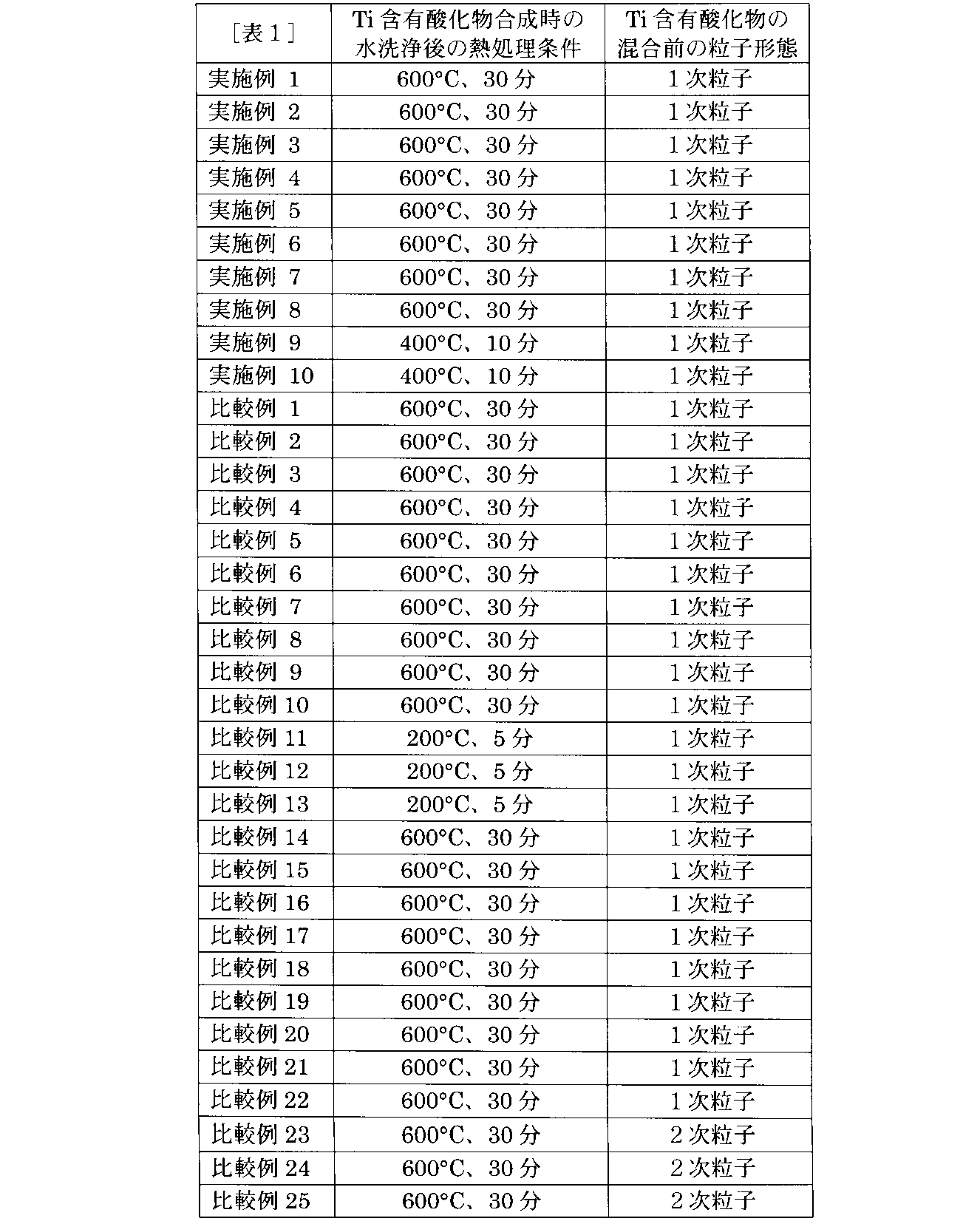

<測定>
上記のとおり製造した各非水電解質電池について、先に説明したFT-EXAFSにより負極の成分分析を行った。得られた動径分布関数における1.1Å以上1.5Å以下の範囲内のピークAと2.8Å以上3.2Å以下の範囲内のピークBとを確認し、それらピーク間の強度比IA/IBを求めた。得られた結果を下記表3に示す。
上記のとおり製造した各非水電解質電池について、先に説明したFT-EXAFSにより負極の成分分析を行った。得られた動径分布関数における1.1Å以上1.5Å以下の範囲内のピークAと2.8Å以上3.2Å以下の範囲内のピークBとを確認し、それらピーク間の強度比IA/IBを求めた。得られた結果を下記表3に示す。
加えて、上述した方法で負極断面のSEM観察を行った。得られた断面SEM像において、負極活物質含有層の断面の面積SE、凝集体の総断面積SG、各凝集体の平均の最小二乗円直径Dg、及び活物質含有層の厚みTeをそれぞれ測定し、比SG/SE及びDg/Teを算出した。それぞれの算出した比を下記表3に示す。
<評価>
実施例1から10及び比較例1から25においてそれぞれ製造した各々の非水電解質電池に対し、下記のとおり性能評価を行った。具体的には、各電池についての大電流性能および寿命性能の評価を行った。
実施例1から10及び比較例1から25においてそれぞれ製造した各々の非水電解質電池に対し、下記のとおり性能評価を行った。具体的には、各電池についての大電流性能および寿命性能の評価を行った。
(大電流性能)
電池の初期抵抗を確認するため、低温条件下における大電流性能を下記低温出力抵抗の測定により評価した。
電池の初期抵抗を確認するため、低温条件下における大電流性能を下記低温出力抵抗の測定により評価した。
先ず、電池を25℃の恒温槽にて、600mA(1C)の充電レートで電池電圧が2.7Vに達するまで定電流充電し、続いて電流値が30mAになるまで定電圧充電した後、10分間の休止時間を設けた。次いで、120mAの定電流で1.5Vまで放電した。このときに得られる放電容量を測定した。
次に、600mA(1C)の充電レートで電池電圧が2.7Vに達するまで定電流充電し、続いて電流値が30mAになるまで定電圧充電した後、放電容量の50%を放電した。
その後、恒温槽の温度を-20℃に設定し、電池を恒温槽内で3時間待機させた。低温(-20℃)の恒温槽にて電池を6Aの定電流で10秒間放電したときの電圧変化を測定した。低温条件での10秒間の放電の際の電圧変化を電流値で除することで算出した値を、低温出力抵抗とした。
(寿命性能)
電池の寿命性能を、次のとおり低温条件のカレンダー試験にて抵抗上昇を測定することで評価した。
電池の寿命性能を、次のとおり低温条件のカレンダー試験にて抵抗上昇を測定することで評価した。
電池をSOC(state of charge、充電状態)が50%になるように充電した後、85℃に設定した恒温槽内に3週間貯蔵した。その後、抵抗上昇率を下記の方法で測定した。
85℃の恒温槽から電池を取り出し、電池の温度が室温に達するまで室温環境下に静置した。続いて電池を25℃の恒温槽に入れ、600mAで1.5Vまで放電した後に10分間の休止時間を設けた。1Aで2.7Vまで充電し、2.7Vにて電流値が30mAになるまで電池を定電圧充電した。その後、10分間の休止時間を設けた。次いで、120mAの定電流で1.5Vまで放電した。このときに得られる放電容量を測定し、回復容量とした。その後、回復容量の50%に相当する容量分を600mAで充電した。恒温槽の温度を-20℃に設定し、電池を恒温槽内で3時間待機させた後、6Aで放電を10秒間行った。10秒間の10C放電の放電抵抗を測定した。
貯蔵前に測定した放電抵抗に対する貯蔵後に測定した放電抵抗の比率を算出し、抵抗上昇率とした。
(体積エネルギー密度)
電池の体積当たりのエネルギー密度を、次のとおり評価した。
電池の体積当たりのエネルギー密度を、次のとおり評価した。
電池の体積エネルギー密度を確認するため、セルの放電容量を測定した。
先ず、電池を25℃の恒温槽にて、600mA(1C)の充電レートで電池電圧が2.7Vに達するまで定電流充電し、続いて電流値が30mAになるまで定電圧充電した後、10分間の休止時間を設けた。次いで、120mAの定電流で1.5Vまで放電した。このときに得られる放電容量を測定した。
放電容量に平均作動電圧を乗じた値をセルの体積で除することで、体積エネルギー密度を算出した。
下記表3に、実施例1から10及び比較例1から25においてそれぞれ製造した各々の非水電解質電池について、性能評価の結果をまとめる。性能評価の結果として、上述した低温出力抵抗(大電流性能)、高温貯蔵時の抵抗上昇率(寿命性能)及び体積当たりのエネルギー密度の評価結果を、比較例21についての測定値を基準値100%とし、この基準値に対する相対的な数値を示す。なお、表3には、上記測定により求めた比IA/IB、SG/SE、及びDg/Teも示す。

実施例1から10では、1/20以上1/2未満の範囲内の値のDg/Teが得られた。これら実施例1から10では、凝集が大きくなく適切な大きさになったため、良好な特性が得られたと推察する。なお、例えば、実施例1と実施例2との間の製造条件の違いのように、アルミニウムアルコキシドの添加の時期によるDg/Teの制御を試みたが、表3に示す結果のとおり、プラネタリーミキサーによる固練りを行う際とビーズミル分散を行う際との間では、アルミニウムアルコキシドの添加時期の変更による影響は見られなかった。
対して、比較例1では混錬後に分散媒をさらに加えて希釈した低い固形分率の状態でアルミニウムアルコキシドを添加したため、アルミニウムアルコキシドと負極活物質との反応頻度が減少した。負極活物質と反応しなかった一部のアルミニウムアルコキシドは負極合材に含まれる結着剤とのみ反応した。結着剤との反応物が抵抗体となり、大電流性能が実施例1に劣ったものと推察する。
比較例2,3,4では、実施例1と比較し弱い分散をかけた。分散が不十分であったため、Dg/Teが1/2以上になったことが示すとおり凝集が大きくなった。分散が不十分であったため、負極活物質表面にアルミニウムアルコキシドが均一に分散されなかったことにより、アルミニウムアルコキシドの被覆に偏りが生じ、凝集している負極活物質は被覆されているが、一次粒子のままの負極活物質は被覆されなかった。被覆されていない負極活物質が存在したことにより、抵抗上昇率が実施例1に劣ったものと推察する。
比較例5,6,7では、実施例1と比較し強い分散をかけた。分散が強過ぎたために、凝集物が小さくなり、大電流性能が実施例1に劣ったものと推察する。
比較例8,9,10では、負極についてのAlのFT-EXAFSより得られた比IA/IBの値が低かった。比較例8, 9, 10の負極に添加したメチルアルミノキサン((Al(CH3)O)n)では、活物質表面上にAl-O-C結合が形成されずに抵抗体となったため効果が得られなかったものと推察される。
比較例11,12,13では、負極についてのAlのFT-EXAFSより得られた比IA/IBの値が高かった。比較例11,12,13で用いた負極活物質(スピネル構造チタン酸リチウム)の調製時に水洗浄後の熱処理の条件を控えめにして残存水分量が多めになったことに起因して、活物質表面上にアルミニウムアルコキシド由来の成分が過剰に形成されたものと推察される。形成されたアルコキシド由来の成分は、アルミニウムアルコキシドの加水分解反応物を含み、加水分解反応物が抵抗体として働いたため、大電流性能が実施例1に劣ったものと推察する。また被覆されてはいるものの、残存水分が副反応を引き起こしたため抵抗上昇が悪化したと推察される。
比較例14,15,16では、アルミニウムアルコキシド溶液の添加量を減少させた。アルミニウムアルコキシド溶液に含まれるアルコール成分も少なくなったことから、結着剤との反応により生じる反応物の量も減少したため、SG/SE及びDg/Teが共に小さいことが示すとおり凝集物が減少し、大電流性能が劣ったものと推察する。また、負極活物質表面の被覆が不十分となり、電解液との副反応が生じ、寿命性能が劣ったものと推察する。
比較例17,18,19では、アルミニウムアルコキシド溶液の添加量を増加させた。アルミニウムアルコキシド溶液に含まれるアルコール成分も多くなったことから、結着剤との反応により生じる反応物の量も増加したため、SG/SE及びDg/Teが共に大きいことが示すとおり凝集物が増大した。サイズの大きな凝集物が多数生じたため、細密充填が不可能となり電極密度が低下し、エネルギー密度が低下した。
比較例20,21,22では、アルミニウムアルコキシド溶液を添加しなかったため、アルミニウムアルコキシド溶液に含まれるアルコール成分と結着剤との反応由来の凝集物が生成しなかったため、大電流性能が実施例1に劣ったものと推察する。また、アルミニウムアルコキシドによる負極活物質表面の被覆が無いため、寿命性能も劣ったものと推察する。
比較例23,24,25では、チタン酸リチウムの一次粒子の粉末ではなく、二次粒子の粉末を使用した。二次粒子の内部にはアルミニウムアルコキシドによる被覆ができないため結着剤との反応物が形成されず抵抗体が存在しないため出力抵抗は改善した。一方で、二次粒子の内部にはアルミニウムアルコキシドによる被覆ができないため寿命性能が劣ったものと推察する。また二次粒子のためアルコキシド添加前の粒子サイズが既に大きいため、凝集体が増大した。サイズの大きな凝集物が多数生じたため、細密充填が不可能となり電極密度が低下し、エネルギー密度が低下した。
以上説明した1以上の実施形態および実施例によれば、チタン含有酸化物を含んだ活物質およびチタン含有酸化物の表面に在る酸化アルミニウム化合物を含む活物質含有層を具備する電極が提供される。チタン含有酸化物の形態としては、一次粒子および複数の一次粒子を含んだ凝集体の両方が含まれる。加えて、活物質含有層に対するAlのFT-EXAFSによる動径分布関数は1.1Å以上1.5Å以下の範囲にピークA及び2.8Å以上3.2Å以下の範囲にピークBを含み、ピークBのピーク強度IBに対するピークAのピーク強度IAの比IA/IBの値が3.5以上9以下である。凝集体の最小二乗円直径Dgは、活物質含有層の厚みTeに対して1/20以上1/2未満である。当該電極は、電気抵抗および抵抗上昇が抑えられており低温性能に優れる電池および電池パックを実現することができる。
本発明のいくつかの実施形態を説明したが、これらの実施形態は、例として提示したものであり、発明の範囲を限定することは意図していない。これら新規な実施形態は、その他の様々な形態で実施されることが可能であり、発明の要旨を逸脱しない範囲で、種々の省略、置き換え、変更を行うことができる。これら実施形態やその変形は、発明の範囲や要旨に含まれると同様に、特許請求の範囲に記載された発明とその均等の範囲に含まれるものである。
以下に、本発明に係る幾つかの実施形態を附記する。
[1] チタン含有酸化物を含む活物質と前記チタン含有酸化物の表面に在る酸化アルミニウム化合物とを含み、前記チタン含有酸化物の形態は一次粒子の形態と複数の前記一次粒子を含んだ凝集体の形態とを含んでいる活物質含有層を具備し、前記活物質含有層に対するAlのK吸収端の広域X線吸収微細構造スペクトルのフーリエ変換による動径分布関数において1.1Å以上1.5Å以下の範囲に現れるピークA及び2.8Å以上3.2Å以下の範囲に現れるピークBを含み、前記ピークBのピーク強度IBに対する前記ピークAのピーク強度IAの比IA/IBの値が3.5以上9以下であり、前記凝集体の最小二乗円直径Dgは、前記活物質含有層の厚みTeに対して1/20以上1/2未満である、電極。
[2] 前記活物質含有層の断面の面積SEに対する前記断面を占める前記凝集体の断面積SGの比SG/SEが1/200以上1/4以下である、[1]に記載の電極。
[3] 前記チタン含有酸化物はスピネル構造を有するチタン酸リチウムを含む、[1]又は[2]に記載の電極。
[4] 正極と、負極と、電解質とを具備し、前記負極は[1]から[3]の何れか1つに記載の電極を含む、電池。
[5] [4]に記載の電池を具備する、電池パック。
[1] チタン含有酸化物を含む活物質と前記チタン含有酸化物の表面に在る酸化アルミニウム化合物とを含み、前記チタン含有酸化物の形態は一次粒子の形態と複数の前記一次粒子を含んだ凝集体の形態とを含んでいる活物質含有層を具備し、前記活物質含有層に対するAlのK吸収端の広域X線吸収微細構造スペクトルのフーリエ変換による動径分布関数において1.1Å以上1.5Å以下の範囲に現れるピークA及び2.8Å以上3.2Å以下の範囲に現れるピークBを含み、前記ピークBのピーク強度IBに対する前記ピークAのピーク強度IAの比IA/IBの値が3.5以上9以下であり、前記凝集体の最小二乗円直径Dgは、前記活物質含有層の厚みTeに対して1/20以上1/2未満である、電極。
[2] 前記活物質含有層の断面の面積SEに対する前記断面を占める前記凝集体の断面積SGの比SG/SEが1/200以上1/4以下である、[1]に記載の電極。
[3] 前記チタン含有酸化物はスピネル構造を有するチタン酸リチウムを含む、[1]又は[2]に記載の電極。
[4] 正極と、負極と、電解質とを具備し、前記負極は[1]から[3]の何れか1つに記載の電極を含む、電池。
[5] [4]に記載の電池を具備する、電池パック。
1…電極群、2…外装部材、3…正極、3a…正極集電体、3b…正極活物質含有層、4…負極、4a…負極集電体、4b…負極活物質含有層、4c…負極集電タブ、4d…凝集体、5…セパレータ、6…負極端子、7…正極端子、11…電極群、12…容器、13…矩形蓋体、14…負極タブ、16…ガラス材、17…正極タブ、18…正極端子、20…電池パック、21…単電池、22…粘着テープ、23…組電池、24…プリント配線基板、25…サーミスタ、26…保護回路、27…外部機器への通電用端子、28…正極側リード、29…正極側コネクタ、30…負極側リード、31…負極側コネクタ、32…配線、33…配線、34a…プラス側配線、34b…マイナス側配線、35…配線、36…保護シート、37…収納容器、38…蓋、51…負極端子、61…正極端子。
Claims (5)
- チタン含有酸化物を含む活物質と前記チタン含有酸化物の表面に在る酸化アルミニウム化合物とを含み、前記チタン含有酸化物の形態は一次粒子の形態と複数の前記一次粒子を含んだ凝集体の形態とを含んでいる活物質含有層を具備し、
前記活物質含有層に対するAlのK吸収端の広域X線吸収微細構造スペクトルのフーリエ変換による動径分布関数において1.1Å以上1.5Å以下の範囲に現れるピークA及び2.8Å以上3.2Å以下の範囲に現れるピークBを含み、前記ピークBのピーク強度IBに対する前記ピークAのピーク強度IAの比IA/IBの値が3.5以上9以下であり、
前記凝集体の最小二乗円直径Dgは、前記活物質含有層の厚みTeに対して1/20以上1/2未満である、電極。 - 前記活物質含有層の断面の面積SEに対する前記断面を占める前記凝集体の断面積SGの比SG/SEが1/200以上1/4以下である、請求項1に記載の電極。
- 前記チタン含有酸化物はスピネル構造を有するチタン酸リチウムを含む、請求項1に記載の電極。
- 正極と、
負極と、
電解質とを具備し、
前記負極は請求項1から3の何れか1項に記載の電極を含む、電池。 - 請求項4に記載の電池を具備する、電池パック。
Priority Applications (2)
| Application Number | Priority Date | Filing Date | Title |
|---|---|---|---|
| PCT/JP2023/011713 WO2024201552A1 (ja) | 2023-03-24 | 2023-03-24 | 電極、電池、及び電池パック |
| JP2025509053A JPWO2024201552A1 (ja) | 2023-03-24 | 2023-03-24 |
Applications Claiming Priority (1)
| Application Number | Priority Date | Filing Date | Title |
|---|---|---|---|
| PCT/JP2023/011713 WO2024201552A1 (ja) | 2023-03-24 | 2023-03-24 | 電極、電池、及び電池パック |
Publications (1)
| Publication Number | Publication Date |
|---|---|
| WO2024201552A1 true WO2024201552A1 (ja) | 2024-10-03 |
Family
ID=92904081
Family Applications (1)
| Application Number | Title | Priority Date | Filing Date |
|---|---|---|---|
| PCT/JP2023/011713 Ceased WO2024201552A1 (ja) | 2023-03-24 | 2023-03-24 | 電極、電池、及び電池パック |
Country Status (2)
| Country | Link |
|---|---|
| JP (1) | JPWO2024201552A1 (ja) |
| WO (1) | WO2024201552A1 (ja) |
Citations (4)
| Publication number | Priority date | Publication date | Assignee | Title |
|---|---|---|---|---|
| JP2012123952A (ja) * | 2010-12-06 | 2012-06-28 | Iwate Univ | 不定比チタン化合物、不定比チタン化合物の金属酸化物被覆複合体、それら化合物の製造方法、及びリチウムイオン二次電池用負極活物質、並びにリチウムイオン二次電池 |
| JP2015099746A (ja) * | 2013-11-20 | 2015-05-28 | 株式会社東芝 | 電池用活物質、非水電解質電池及び電池パック |
| CN108281641A (zh) * | 2018-02-08 | 2018-07-13 | 天津普兰能源科技有限公司 | 一种双重包覆的钛酸锂电池材料及制备方法 |
| JP2018537833A (ja) * | 2015-12-24 | 2018-12-20 | エルジー・ケム・リミテッド | 出力特性が向上した負極活物質及びこれを含む電気化学素子用電極 |
-
2023
- 2023-03-24 JP JP2025509053A patent/JPWO2024201552A1/ja active Pending
- 2023-03-24 WO PCT/JP2023/011713 patent/WO2024201552A1/ja not_active Ceased
Patent Citations (4)
| Publication number | Priority date | Publication date | Assignee | Title |
|---|---|---|---|---|
| JP2012123952A (ja) * | 2010-12-06 | 2012-06-28 | Iwate Univ | 不定比チタン化合物、不定比チタン化合物の金属酸化物被覆複合体、それら化合物の製造方法、及びリチウムイオン二次電池用負極活物質、並びにリチウムイオン二次電池 |
| JP2015099746A (ja) * | 2013-11-20 | 2015-05-28 | 株式会社東芝 | 電池用活物質、非水電解質電池及び電池パック |
| JP2018537833A (ja) * | 2015-12-24 | 2018-12-20 | エルジー・ケム・リミテッド | 出力特性が向上した負極活物質及びこれを含む電気化学素子用電極 |
| CN108281641A (zh) * | 2018-02-08 | 2018-07-13 | 天津普兰能源科技有限公司 | 一种双重包覆的钛酸锂电池材料及制备方法 |
Also Published As
| Publication number | Publication date |
|---|---|
| JPWO2024201552A1 (ja) | 2024-10-03 |
Similar Documents
| Publication | Publication Date | Title |
|---|---|---|
| US10361430B2 (en) | Active material, nonaqueous electrolyte battery, battery pack, and vehicle | |
| JP6523115B2 (ja) | 電池用活物質、負極、非水電解質電池、電池パック及び車 | |
| US10199648B2 (en) | Electrode, nonaqueous electrolyte battery, battery pack and vehicle | |
| CN105122513B (zh) | 非水电解质电池用活性物质、非水电解质电池及电池包 | |
| JP2015084321A (ja) | 電池用活物質材料及びその製造方法、非水電解質電池、並びに電池パック | |
| CN107204443B (zh) | 活性物质、非水电解质电池、电池包及车辆 | |
| EP3082182B1 (en) | Active material, nonaqueous electrolyte battery, battery module, battery pack and vehicle | |
| CN104638232A (zh) | 电池用活性物质的制造方法、电池用活性物质、非水电解质电池及电池包 | |
| JP6571284B2 (ja) | 電極、非水電解質電池及び電池パック | |
| CN109196694B (zh) | 非水电解质电池及电池包 | |
| WO2018020669A1 (ja) | 非水電解質電池及び電池パック | |
| JP7781906B2 (ja) | 非水電解質二次電池用の電極、非水電解質二次電池、及び電池パック | |
| KR20170107889A (ko) | 활물질, 비수전해질 전지, 전지 팩 및 차량 | |
| US10224545B2 (en) | Active material, nonaqueous electrolyte battery, battery pack, and vehicle | |
| US20230238523A1 (en) | Electrode, battery, and battery pack | |
| WO2024201552A1 (ja) | 電極、電池、及び電池パック | |
| JP7106754B2 (ja) | 電極、電池及び電池パック | |
| JP7834844B2 (ja) | 電極、電池、及び電池パック | |
| JP6965438B2 (ja) | 活物質、電極、非水電解質電池及び電池パック |
Legal Events
| Date | Code | Title | Description |
|---|---|---|---|
| 121 | Ep: the epo has been informed by wipo that ep was designated in this application |
Ref document number: 23930194 Country of ref document: EP Kind code of ref document: A1 |
|
| WWE | Wipo information: entry into national phase |
Ref document number: 2025509053 Country of ref document: JP |
|
| NENP | Non-entry into the national phase |
Ref country code: DE |
|
| 122 | Ep: pct application non-entry in european phase |
Ref document number: 23930194 Country of ref document: EP Kind code of ref document: A1 |