WO2024195691A1 - 防護服 - Google Patents
防護服 Download PDFInfo
- Publication number
- WO2024195691A1 WO2024195691A1 PCT/JP2024/010041 JP2024010041W WO2024195691A1 WO 2024195691 A1 WO2024195691 A1 WO 2024195691A1 JP 2024010041 W JP2024010041 W JP 2024010041W WO 2024195691 A1 WO2024195691 A1 WO 2024195691A1
- Authority
- WO
- WIPO (PCT)
- Prior art keywords
- fabric
- protective clothing
- protective
- joint
- static friction
- Prior art date
- Legal status (The legal status is an assumption and is not a legal conclusion. Google has not performed a legal analysis and makes no representation as to the accuracy of the status listed.)
- Ceased
Links
Images




Classifications
-
- A—HUMAN NECESSITIES
- A41—WEARING APPAREL
- A41D—OUTERWEAR; PROTECTIVE GARMENTS; ACCESSORIES
- A41D13/00—Professional, industrial or sporting protective garments, e.g. surgeons' gowns or garments protecting against blows or punches
- A41D13/02—Overalls, e.g. bodysuits or bib overalls
-
- A—HUMAN NECESSITIES
- A41—WEARING APPAREL
- A41D—OUTERWEAR; PROTECTIVE GARMENTS; ACCESSORIES
- A41D27/00—Details of garments or of their making
- A41D27/28—Means for ventilation
-
- A—HUMAN NECESSITIES
- A41—WEARING APPAREL
- A41D—OUTERWEAR; PROTECTIVE GARMENTS; ACCESSORIES
- A41D31/00—Materials specially adapted for outerwear
-
- A—HUMAN NECESSITIES
- A41—WEARING APPAREL
- A41D—OUTERWEAR; PROTECTIVE GARMENTS; ACCESSORIES
- A41D31/00—Materials specially adapted for outerwear
- A41D31/02—Layered materials
-
- A—HUMAN NECESSITIES
- A41—WEARING APPAREL
- A41D—OUTERWEAR; PROTECTIVE GARMENTS; ACCESSORIES
- A41D31/00—Materials specially adapted for outerwear
- A41D31/04—Materials specially adapted for outerwear characterised by special function or use
-
- A—HUMAN NECESSITIES
- A41—WEARING APPAREL
- A41D—OUTERWEAR; PROTECTIVE GARMENTS; ACCESSORIES
- A41D31/00—Materials specially adapted for outerwear
- A41D31/04—Materials specially adapted for outerwear characterised by special function or use
- A41D31/10—Impermeable to liquids, e.g. waterproof; Liquid-repellent
- A41D31/102—Waterproof and breathable
-
- B—PERFORMING OPERATIONS; TRANSPORTING
- B32—LAYERED PRODUCTS
- B32B—LAYERED PRODUCTS, i.e. PRODUCTS BUILT-UP OF STRATA OF FLAT OR NON-FLAT, e.g. CELLULAR OR HONEYCOMB, FORM
- B32B25/00—Layered products comprising a layer of natural or synthetic rubber
- B32B25/10—Layered products comprising a layer of natural or synthetic rubber next to a fibrous or filamentary layer
-
- B—PERFORMING OPERATIONS; TRANSPORTING
- B32—LAYERED PRODUCTS
- B32B—LAYERED PRODUCTS, i.e. PRODUCTS BUILT-UP OF STRATA OF FLAT OR NON-FLAT, e.g. CELLULAR OR HONEYCOMB, FORM
- B32B5/00—Layered products characterised by the non- homogeneity or physical structure, i.e. comprising a fibrous, filamentary, particulate or foam layer; Layered products characterised by having a layer differing constitutionally or physically in different parts
- B32B5/22—Layered products characterised by the non- homogeneity or physical structure, i.e. comprising a fibrous, filamentary, particulate or foam layer; Layered products characterised by having a layer differing constitutionally or physically in different parts characterised by the presence of two or more layers which are next to each other and are fibrous, filamentary, formed of particles or foamed
- B32B5/24—Layered products characterised by the non- homogeneity or physical structure, i.e. comprising a fibrous, filamentary, particulate or foam layer; Layered products characterised by having a layer differing constitutionally or physically in different parts characterised by the presence of two or more layers which are next to each other and are fibrous, filamentary, formed of particles or foamed one layer being a fibrous or filamentary layer
-
- D—TEXTILES; PAPER
- D04—BRAIDING; LACE-MAKING; KNITTING; TRIMMINGS; NON-WOVEN FABRICS
- D04H—MAKING TEXTILE FABRICS, e.g. FROM FIBRES OR FILAMENTARY MATERIAL; FABRICS MADE BY SUCH PROCESSES OR APPARATUS, e.g. FELTS, NON-WOVEN FABRICS; COTTON-WOOL; WADDING ; NON-WOVEN FABRICS FROM STAPLE FIBRES, FILAMENTS OR YARNS, BONDED WITH AT LEAST ONE WEB-LIKE MATERIAL DURING THEIR CONSOLIDATION
- D04H3/00—Non-woven fabrics formed wholly or mainly of yarns or like filamentary material of substantial length
- D04H3/08—Non-woven fabrics formed wholly or mainly of yarns or like filamentary material of substantial length characterised by the method of strengthening or consolidating
- D04H3/16—Non-woven fabrics formed wholly or mainly of yarns or like filamentary material of substantial length characterised by the method of strengthening or consolidating with bonds between thermoplastic filaments produced in association with filament formation, e.g. immediately following extrusion
Definitions
- the present invention relates to protective clothing.
- Patent Document 1 discloses protective clothing made of a porous film that is both oil-resistant and moisture-permeable
- Patent Document 2 discloses protective clothing that combines a highly water-resistant fabric with a highly breathable fabric
- Patent Document 3 discloses protective clothing that combines a porous film with a highly breathable fabric.
- the protective clothing described in Patent Document 1 uses a fabric laminated with a porous film having fine pores (average pore size 0.06 to 0.40 ⁇ m) to ensure oil resistance.
- this protective clothing has no breathability, and compared to protective clothing made only of breathable nonwoven fabric, it is prone to heat and humidity buildup within the clothing, making it less comfortable and unsuitable for long periods of work in high-temperature environments from the perspective of the risk of heatstroke.
- the protective clothing described in Patent Document 2 uses nonwoven fabric in which fine fiber meltblown nonwoven fabric (fiber diameter 1 ⁇ m) is laminated for most of the protective clothing fabric to ensure water resistance and breathability.
- the pore size of meltblown nonwoven fabric is larger than that of porous film, and because oil has a lower surface tension than water, oil easily penetrates into the protective clothing, and the wearer is easily contaminated with oil, which means that the protective clothing has poor oil resistance.
- the protective clothing described in Patent Document 3 has a fabric laminated with a porous film placed in a specific area of a hood made of breathable nonwoven fabric (laminated nonwoven fabric of spunbond nonwoven fabric/meltblown nonwoven fabric/spunbond nonwoven fabric). Furthermore, in order to configure protective clothing with excellent oil resistance, dust resistance, and comfort, it is possible to use a similar configuration for parts other than the hood. However, there is a problem that seam deviations occur during sewing because the porous film surface of the fabric using the porous film and the fabric using the nonwoven fabric have different slipperiness on the fabric surface. The inventors have found that such seam deviations are a factor that reduces productivity in disposable protective clothing applications, which require faster production speeds.
- the present invention aims to provide protective clothing that is oil-resistant, dust-proof, comfortable, and easy to manufacture.
- the present invention provides protective clothing having the following configuration: (1) A protective suit having a first fabric and a second fabric and a joint formed by joining the first fabric and the second fabric, the first fabric having a first surface and a second surface, the second fabric having a third surface and a fourth surface, the ratio of the static friction coefficient of the second surface of the first fabric to the static friction coefficient of the fourth surface of the second fabric being 0.80 to 1.20, the first surface of the first fabric being formed of a resin layer, the resin layer being disposed on the side opposite the human body side when the protective suit is worn, the second surface of the first fabric and the third and fourth surfaces of the second fabric being formed of a fiber layer, and the joint being configured such that one sheet of the first fabric and one sheet of the second fabric are joined together by at least one material selected from the group consisting of sewing thread, welding, and adhesive, A protective garment in which a first surface of the first fabric and a third surface of the second fabric are disposed opposite each other at the joint.
- (11) The protective suit according to (9) or (10), wherein the laminated fabric constitutes at least a part of a rear body of the protective suit.
- the present invention makes it possible to provide protective clothing that is oil-resistant, dust-proof, comfortable, and easy to manufacture.
- FIG. 1 is a schematic front view of a protective suit according to one embodiment of the present invention.
- FIG. 2 is a schematic rear view of the protective suit according to one embodiment of the present invention.
- FIG. 3 is a schematic diagram of portion A on the back of the protective clothing of one embodiment of the present invention.
- FIG. 4 is a schematic cross-sectional view of a first fabric provided in the protective clothing of the present invention.
- FIG. 5 is a schematic cross-sectional view of a second fabric provided in the protective clothing of the present invention.
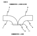
- FIG. 6 is a schematic cross-sectional view of a joint portion of the protective clothing of the present invention, where a first fabric and a second fabric are joined together using sewing thread.
- FIG. 7 is a schematic cross-sectional view of a joint portion of the protective clothing of the present invention, where a first fabric and a second fabric are joined by welding.
- FIG. 8 is a schematic cross-sectional view of a joint portion of the protective clothing of the present invention, where a first fabric and a second fabric are joined with an adhesive.
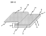
- FIG. 9 is a schematic front view of the laminated fabric.
- FIG. 10 is a schematic cross-sectional view of the laminated fabric.
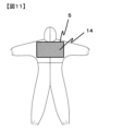
- FIG. 11 is a schematic diagram of the back body of a protective garment comprising a laminated fabric of one embodiment of the present invention.
- the protective clothing of the present invention comprises a first fabric and a second fabric, and is provided with a joint formed by joining the first fabric and the second fabric, the first fabric having a first surface and a second surface, the second fabric having a third surface and a fourth surface, the ratio of the static friction coefficient of the second surface of the first fabric to the static friction coefficient of the fourth surface of the second fabric, i.e., the ratio of the static friction coefficient of the second surface of the first fabric to the static friction coefficient of the fourth surface of the second fabric, is 0.80 to 1.20, and the first surface of the first fabric , a resin layer, which is positioned on the side opposite the human body when the protective clothing is worn, the second side of the first fabric and the third and fourth sides of the second fabric are formed of a fiber layer, and the joint is configured by joining one sheet of the first fabric and one sheet of the second fabric with at least one material selected from the group consisting of sewing thread, welding, and adhesive, and the first side of the first fabric and the third side of the second fabric are positioned to face
- the protective clothing of the present invention has a first fabric with a first surface formed of a resin layer, and further, in this protective clothing, this resin layer is located on the opposite side to the human body when worn. This makes the protective clothing excellent in oil resistance and dust resistance. Furthermore, in addition to the first fabric, the protective clothing of the present invention also has a second fabric with excellent breathability, both sides of which are formed of fiber layers, and therefore is also excellent in dust resistance and comfort. Furthermore, one of the further features of the protective clothing of the present invention, which is excellent in oil resistance, dust resistance and comfort due to the above-mentioned characteristic configuration, is the joint provided in the protective clothing.
- this joint is configured such that one sheet of the first fabric and one sheet of the second fabric are joined by at least one selected from the group consisting of sewing thread, welding and adhesive, and further, at this joint, the first surface of the first fabric and the third surface of the second fabric face each other.
- the first surface of the first fabric and the third surface of the second fabric face each other in this joint, the second surface of the first fabric forms one outermost surface of the joint, and the fourth surface of the second fabric forms the other outermost surface of the joint.
- this protective clothing when the joint is made using a sewing machine, the second surface of the first fabric forming one outermost surface of the joint contacts the presser foot of the sewing machine, and the fourth surface of the second fabric forming the other outermost surface of the joint contacts the feed dog of the sewing machine, or the fourth surface of the second fabric forming one outermost surface of the joint contacts the presser foot of the sewing machine, and the second surface of the first fabric forming the other outermost surface of the joint contacts the feed dog of the sewing machine.
- the ratio of the static friction coefficient of the second surface of the first fabric to the static friction coefficient of the fourth surface of the second fabric is 0.80 to 1.20, that is, the static friction coefficient of the second surface and the static friction coefficient of the fourth surface are the same, or, even if there is a difference between the static friction coefficients of the two, the difference is small, thereby suppressing the occurrence of seam slippage, and as a result, the productivity of the protective clothing of the present invention is excellent.
- the ratio of the static friction coefficient of the second surface of the first fabric to the static friction coefficient of the fourth surface of the second fabric has a lower limit of 0.85 or more, and even more preferable that it is 0.90 or more.
- the ratio of the static friction coefficient of the second surface of the first fabric to the static friction coefficient of the fourth surface of the second fabric has an upper limit of 1.15 or less, and even more preferable that it is 1.10 or less.
- the protective clothing of the present invention which has all of the above characteristics, is oil-resistant, dust-resistant, comfortable, and highly manufacturable.
- Fig. 1 shows a schematic front view of protective clothing according to one embodiment of the present invention, which is a one-piece protective clothing having a portion 1 covering the chest of the wearer, a portion 4 covering the underarms of the wearer, and a portion 3 covering the head of the wearer.
- Fig. 2 shows a schematic back view of protective clothing according to one embodiment of the present invention, which is a one-piece protective clothing having a portion 2 covering the back of the wearer, a portion 4 covering the underarms of the wearer, and a portion 3 covering the head of the wearer.
- Fig. 3 shows a schematic view of portion A on the back of protective clothing according to one embodiment of the present invention, which is a one-piece protective clothing having portion A5.
- Figure 4 shows a schematic cross-sectional view of the first fabric of the protective clothing of the present invention, which has a first surface 6 of the first fabric and a second surface 7 of the first fabric.
- Figure 5 shows a schematic cross-sectional view of the second fabric of the protective clothing of the present invention, which has a third surface 8 of the second fabric and a fourth surface 9 of the second fabric.
- FIG. 6 shows a conceptual diagram of a cross section of a joint 10 in which a first fabric and a second fabric are joined using sewing thread 11, where the first surface 6 of the first fabric and the third surface 8 of the second fabric are adjacent to each other.
- FIG. 7 shows a conceptual diagram of a cross section of a joint 10 in which a first fabric and a second fabric are joined by welding 12, where the first surface 6 of the first fabric and the third surface 8 of the second fabric are adjacent to each other.
- FIG. 6 shows a conceptual diagram of a cross section of a joint 10 in which a first fabric and a second fabric are joined using sewing thread 11, where the first surface 6 of the first fabric and the third surface 8 of the second fabric are adjacent to each other.
- FIG. 7 shows a conceptual diagram of a cross section of a joint 10 in which a first fabric and a second fabric are joined by welding 12, where the first surface 6 of the first fabric and the third surface 8 of the second fabric are adjacent to each other.
- the second surface 7 of the first fabric and the fourth surface 9 of the second fabric are the surfaces that come into contact with the equipment that performs the joining process.
- the surface that contacts the presser foot of the sewing machine becomes the second surface 7 of the first fabric
- the surface that contacts the feed dog of the sewing machine becomes the fourth surface 9 of the second fabric.
- the reverse is also possible. In this case, the difference in slipperiness of each surface causes sewing slippage.
- the first surface of the first fabric faces the third surface of the second fabric at the joint.
- the joint is created using a sewing machine during the manufacturing process of this protective clothing, the first surface of the first fabric comes into contact with the third surface of the second fabric.
- the ratio of the static friction coefficient of the first surface of the first fabric to the static friction coefficient of the third surface of the second fabric is 1.50 to 2.20.
- the ratio of the static friction coefficients of the first surface and the third surface is 1.50 or more, that is, the surface with a high static friction coefficient is held so as to adhere to the surface with a low static friction coefficient, the misalignment at the contact surfaces of the first fabric and the second fabric is reduced, and the occurrence of sewing misalignment is suppressed.
- the ratio of the static friction coefficients of the first surface and the third surface is 2.20 or less, that is, by reducing the difference in the static friction coefficients to be equal to or less than the upper limit, the misalignment between the surfaces can be made constant, the misalignment at the contact surface between the first fabric and the second fabric is reduced, and the occurrence of sewing misalignment is suppressed. Therefore, the combined factor of setting the ratio of the static friction coefficient of the second surface of the first fabric to the static friction coefficient of the fourth surface of the second fabric to 0.80 to 1.20 results in even better productivity for the protective clothing of the present invention.
- the ratio of the static friction coefficient of the first surface of the first fabric to the static friction coefficient of the third surface of the second fabric has a lower limit of 1.60 or more, and even more preferable that it is 1.70 or more.
- the ratio of the static friction coefficient of the first surface of the first fabric to the static friction coefficient of the third surface of the second fabric has an upper limit of 2.10 or less, and even more preferable that it is 2.00 or less.
- the first surface 6 of the first fabric is formed from a resin layer, and the resin layer is arranged on the side opposite the human body when the protective clothing is worn, so that the area having the first fabric has excellent oil resistance and dust resistance.
- the second surface 7 of the first fabric and the fourth surface 9 of the second fabric are made of fiber layers, which provides a pleasant feel against the wearer's skin and excellent wearing comfort.
- the third surface 8 and fourth surface 9 of the second fabric are formed from fiber layers, resulting in a breathable structure and a protective suit that is comfortable to wear.
- the first fabric of the protective clothing of the present invention has superior oil resistance and dust resistance compared to the second fabric, and is arranged to improve the oil resistance and dust resistance when the protective clothing is worn.
- the first fabric of the present invention has a first surface and a second surface.
- the first surface is formed of a resin layer
- the second surface is formed of a fiber layer.
- the resin layer forming the first surface of the first fabric provides oil resistance and dust resistance
- the fiber layer forming the second surface provides a comfortable feel to the wearer of the first fabric. Due to the above circumstances, the protective clothing of the present invention provides excellent comfort to the wearer.
- the first fabric preferably has an oil resistance of grade 3 or higher in an oil resistance test, more preferably grade 4 or higher, and even more preferably grade 5 or higher.
- oil resistance of the first fabric is grade 3 or higher, protective clothing using the first fabric can suppress the penetration of oil into the protective clothing when worn. As a result, the protective clothing has excellent oil resistance.
- the thickness of the resin layer forming the first surface of the first fabric and the porosity of the resin layer can be appropriately adjusted to the preferred range described below.
- the first fabric preferably has a moisture permeability of 200 g/m 2 /hr or more, more preferably 250 g/m 2 /hr or more, and even more preferably 300 g/m 2 /hr or more.
- the moisture permeability of the first fabric is preferably 500 g/m 2 /hr or less, and more preferably 400 g/m 2 /hr or less.
- the protective clothing using the first fabric has high protective properties such as oil resistance and dust resistance, and the protective clothing using the first fabric has excellent oil resistance and dust resistance when worn.
- this can be achieved by appropriately adjusting the thickness and porosity of the resin layer forming the first surface of the first fabric to within the preferred ranges described below.
- the first fabric preferably has a collection efficiency of 50% or more, more preferably 80% or more, and even more preferably 90% or more.
- a first fabric with high collection efficiency protective clothing using the first fabric can suppress the penetration of dust into the protective clothing when worn. As a result, the protective clothing has excellent dust resistance.
- the fabric is not breathable due to the resin layer, the collection efficiency cannot be measured, but since there are no gaps through which air can pass through the fabric, protective clothing using the fabric has excellent dust resistance.
- this can be achieved by appropriately adjusting the thickness of the resin layer and the porosity of the resin layer in the resin layer forming the first surface of the first fabric to the preferred range described below.
- the method for bonding the resin layer forming the first surface of the first fabric and the fiber layer forming the second surface of the first fabric is not particularly limited.
- the bonding method may be embossing, in which a concave-convex roll and a pair of rolls are pressed together and heat, ultrasonic waves, or high frequency waves are applied to these rolls to effect partial bonding; sintering, in which a powder having a low melting point adhesive component is sprayed, heat treated, and partially bonded; or hot melt processing, in which a hot melt adhesive or the like is sprayed to partially bond the resin layer forming the first surface and the fiber layer forming the second surface.
- partial bonding of the first surface and the second surface is preferable because it results in a fabric with excellent moisture permeability.
- the first fabric of the present invention may have, in addition to the first surface and the second surface, an intermediate layer between the resin layer forming the first surface and the fiber layer forming the second surface.
- the intermediate layer is, for example, a resin layer
- the oil resistance and dust resistance of the first fabric are improved.
- the resin layer of the intermediate layer may be the same as the resin layer forming the first surface of the first fabric, or may be different.
- the intermediate layer is, for example, a fiber layer
- the dust resistance of the first fabric is improved.
- the fiber layer of the intermediate layer may be the same as the fiber layer forming the second surface of the first fabric, or may be different.
- the second fabric of the protective clothing of the present invention is more breathable than the first fabric, which contributes to improving the comfort of wearing the protective clothing.
- the second fabric of the protective clothing of the present invention has a third surface and a fourth surface, the third surface being formed from a fiber layer, and the fourth surface also being formed from a fiber layer. Because the third surface and the fourth surface of the second fabric are both formed from fiber layers, the fabric can be made to have excellent breathability, which makes the protective clothing highly comfortable to wear.
- the fourth surface of the second fabric is formed from a fiber layer, it feels good against the wearer's skin, resulting in excellent wearing comfort for the protective clothing.
- the second fabric has a lower limit water pressure resistance of preferably 500 mmH 2 O (4.90 kPa) or more, more preferably 700 mmH 2 O (6.86 kPa) or more, and even more preferably 1000 mmH 2 O (9.81 kPa) or more.
- the upper limit of the water pressure resistance of the second fabric is not particularly limited.
- the water pressure resistance of the second fabric is preferably 3000 mmH 2 O (29.4 kPa) or less, and more preferably 2000 mmH 2 O (19.6 kPa) or less.
- the protective clothing has excellent water resistance and also has the effect of suppressing the penetration of oil.
- the productivity of the fabric is improved.
- the fiber diameter of the fiber layer forming the third surface and the fiber layer forming the fourth surface which will be described later, is equal to or greater than the lower limit of the fiber diameter and the lower limit of the basis weight.
- the second fabric may have an intermediate fiber layer between the fiber layer forming the third surface and the fiber layer forming the fourth surface, in addition to the fiber layer forming the third surface and the fiber layer forming the fourth surface.
- the second fabric has better water pressure resistance while maintaining breathability.
- the protective clothing can be configured to have better water resistance while maintaining comfort.
- the intermediate fiber layer is made of a fiber structure such as a woven fabric, knitted fabric, nonwoven fabric, or paper.
- the fiber layer is preferably a nonwoven fabric from the viewpoints of cost and water pressure resistance.
- Suitable nonwoven fabrics include wet-laid nonwoven fabrics, resin-bonded nonwoven fabrics, thermal-bonded nonwoven fabrics, spunbonded nonwoven fabrics, melt-blown nonwoven fabrics, needle-punched nonwoven fabrics, water-jet punched nonwoven paper fabrics, and flash-spun nonwoven fabrics.
- melt-blown nonwoven fabrics have a small fiber diameter and are preferred from the viewpoint of water pressure resistance.
- the average fiber diameter of the fibers constituting the intermediate fiber layer is preferably 1 ⁇ m or more, more preferably 2 ⁇ m or more, and even more preferably 3 ⁇ m or more.
- the average fiber diameter of the fibers is preferably 10 ⁇ m or less, more preferably 8 ⁇ m or less, and even more preferably 6 ⁇ m or less.
- the average fiber diameter is equal to or greater than the above-mentioned lower limit, a fiber layer having fine pores can be created, improving water pressure resistance.
- the average fiber diameter is equal to or less than the above-mentioned upper limit, penetration of oil and dust can be suppressed.
- the second fabric preferably has an air permeability of 5 cm 3 /cm 2 /s or more, more preferably 30 cm 3 /cm 2 /s or more, and even more preferably 80 cm 3 /cm 2 /s or more.
- the second fabric preferably has an air permeability of 130 cm 3 /cm 2 /s or less, more preferably 120 cm 3 /cm 2 /s or less, and even more preferably 110 cm 3 /cm 2 /s or less.
- Means for adjusting the breathability of the second fabric to the above-mentioned preferred range include appropriately adjusting the fiber diameter of the fibers constituting the fiber layer forming the third side of the second fabric and the fiber layer forming the fourth side of the second fabric and the basis weight of each layer within the preferred ranges described below.
- the second fabric preferably has an oil resistance of grade 1 or higher in an oil resistance test, more preferably grade 2 or higher, and even more preferably grade 3 or higher.
- the oil resistance of the second fabric is grade 1 or higher, protective clothing using the second fabric can suppress the penetration of oil into the protective clothing when worn. As a result, the protective clothing has excellent oil resistance.
- One way to set the oil resistance of the second fabric within the above-mentioned preferred range is to appropriately adjust the fiber diameter of the fibers constituting the fiber layer forming the third surface of the second fabric and the fiber layer forming the fourth surface of the second fabric, and the basis weight of each layer, to the preferred ranges described below.
- the second fabric preferably has a moisture permeability of 250 g/m 2 /hr or more, more preferably 300 g/m 2 /hr or more, and even more preferably 350 g/m 2 /hr or more.
- the moisture permeability of the second fabric is preferably 500 g/m 2 /hr or less, more preferably 450 g/m 2 /hr or less, and even more preferably 400 g/m 2 /hr or less.
- Means for adjusting the moisture permeability of the second fabric to the above-mentioned preferred range include appropriately adjusting the fiber diameter of the fibers constituting the fiber layer forming the third surface of the second fabric and the fiber layer forming the fourth surface of the second fabric and the basis weight of each layer to within the preferred ranges described below.
- the second fabric preferably has a collection efficiency of 50% or more, more preferably 80% or more, and even more preferably 90% or more.
- a second fabric with high collection efficiency protective clothing using the second fabric can suppress the penetration of dust into the protective clothing when worn.
- the protective clothing has excellent dust resistance.
- One way to set the collection efficiency of the second fabric in the above-mentioned preferred range is to appropriately adjust the fiber diameter of the fibers constituting the fiber layer forming the third surface of the second fabric and the fiber layer forming the fourth surface of the second fabric, and the basis weight of each layer, to the preferred ranges described below.
- the method for bonding the fiber layer forming the third surface of the second fabric and the fiber layer forming the fourth surface is not particularly limited.
- the bonding method may be embossing, in which a concave-convex roll and a pair of rolls are pressed together and heat, ultrasonic waves, or high frequency waves are applied to these rolls to partially bond them together; sintering, in which a powder containing a low-melting adhesive component is sprayed, heat-treated, and partially bonded; or hot melt processing, in which a hot melt adhesive or the like is sprayed to partially bond the fiber layer forming the third surface and the fiber layer forming the fourth surface.
- the resin layer forming the first surface has oil resistance to suppress the penetration of oil and dust resistance to suppress the penetration of dust.
- the resin layer can be made of a non-porous resin or a resin with fine holes formed by a resin coating process or a film lamination process, etc., to suppress the penetration of oil and dust.
- the resin layer preferably has a thickness of 10 ⁇ m or more, more preferably 20 ⁇ m or more, and even more preferably 30 ⁇ m or more.
- the thickness of the resin layer is preferably 100 ⁇ m or less, more preferably 80 ⁇ m or less, and even more preferably 60 ⁇ m or less.
- a resin layer having a thickness of 10 ⁇ m or more can suppress the penetration of oil and dust, resulting in excellent oil resistance.
- a resin layer having a thickness of 100 ⁇ m or less can easily transmit humidity, making it easier to reduce humidity inside the protective clothing when worn.
- the resin forming the resin layer is not particularly limited.
- the resin include polyolefin, polycarbonate, polyamide, polyimide, polyamideimide, aromatic polyamide, and fluororesin.
- polyolefin resin is preferred from the viewpoints of heat resistance, moldability, reduction in production costs, chemical resistance, flexibility, etc., and polyethylene is more preferred.
- the main component of the resin constituting the resin layer is polyethylene.
- main component means that a specific component accounts for more than 50% by mass of the total components.
- the resin layer is preferably a porous film having fine pores.
- a porous film has fine pores and has high moisture permeability that allows moisture inside the garment to be released to the outside of the garment.
- a porous film refers to a film having a large number of fine pores and a porosity of 5% or more.
- the porosity of the porous film is preferably 30% or more, and more preferably 40% or more.
- the porosity of the porous film is preferably 70% or less, and more preferably 60% or less.
- the porosity is equal to or greater than the lower limit mentioned above, the moisture permeability is increased.
- the porosity is equal to or less than the upper limit mentioned above, the penetration of oil and dust can be suppressed.
- the first fabric can achieve both oil resistance, dust resistance, and moisture permeability.
- Methods for forming micropores in porous films can be broadly divided into wet methods and dry methods.
- Wet methods include phase separation and track etching, while dry methods include particle addition, crystal interface peeling, ⁇ crystallization, and crazing.
- the particle addition method is preferred from the viewpoints of excellent oil resistance, comfort, and productivity.
- a resin to which particles with a diameter of several microns have been added is extruded, formed into a sheet, and stretched uniaxially or biaxially to form microscopic through-holes. This method is inexpensive and is preferred for disposable protective clothing applications.
- the second side of the first dough, and the third and fourth sides of the second dough The second side of the first fabric, and the third and fourth sides of the second fabric of the protective clothing of the present invention will be described below. Note that the second side of the first fabric, and the third and fourth sides of the second fabric may be collectively referred to as the second to fourth sides hereinafter.
- the fiber layers forming the second to fourth surfaces are made of fiber structures such as woven fabrics, knitted fabrics, nonwoven fabrics, and paper.
- the fiber layers are preferably nonwoven fabrics from the viewpoints of cost, tensile strength, and the like.
- the nonwoven fabrics are preferably wet-laid nonwoven fabrics, resin-bonded nonwoven fabrics, thermal-bonded nonwoven fabrics, spunbonded nonwoven fabrics, needle-punched nonwoven fabrics, water-jet-punched nonwoven paper fabrics, or flash-spun nonwoven fabrics.
- spunbonded nonwoven fabrics are preferred from the viewpoints of cost, tensile strength, and the like, and protective clothing using fabrics containing spunbonded nonwoven fabrics provides a good feel to the wearer's skin and excellent comfort to the wearer.
- the average fiber diameter of the fibers constituting the spunbonded nonwoven fabric is preferably 5 ⁇ m or more, more preferably 7 ⁇ m or more, and even more preferably 9 ⁇ m or more.
- the average fiber diameter of the fibers is preferably 40 ⁇ m or less, more preferably 30 ⁇ m or less, even more preferably 25 ⁇ m or less, and particularly preferably 15 ⁇ m or less.
- the basis weight of the fiber layers forming the second to fourth surfaces is preferably 10 g/m 2 or more, more preferably 15 g/m 2 or more, and even more preferably 20 g/m 2 or more.
- the basis weight of the fiber layers is preferably 50 g/m 2 or less, more preferably 40 g/m 2 or less, and even more preferably 30 g/m 2 or less.
- the basis weight is equal to or more than the above-mentioned lower limit, the first fabric can increase the sheet strength. Therefore, protective clothing using a fabric having the above-mentioned fiber layer reduces fabric tearing due to friction or snagging during work.
- the basis weight is equal to or less than the above-mentioned upper limit, the fabric becomes soft, the feel of the wearer is good, and the comfort of wearing the protective clothing is improved.
- the fiber layers forming the second to fourth surfaces may be given functions as long as the effects of this embodiment are not impaired.
- the fiber layers forming the second to fourth surfaces may be given functions such as water repellency, oil repellency, antistatic, flame retardant, antibacterial, antiviral, and antifungal properties.
- the material of the fiber layers forming the second to fourth surfaces is not particularly limited.
- the fiber material may be polyolefins such as polyethylene and polypropylene, polyesters such as polyethylene terephthalate and polylactic acid, polycarbonate, polystyrene, polyphenylene sulfide, fluororesins, and mixtures of these.
- the form of the fiber using a mixture of two or more components may be a fiber using a copolymer of two or more resins, or a mixed fiber in which fibers made of multiple single components exist as a nonwoven fabric, or a single fiber may have multiple components, such as a core-sheath type, sea-island type, or side-by-side type.
- the static friction coefficient of each of the second to fourth surfaces is preferably 0.50 or less, more preferably 0.45 or less, and even more preferably 0.40 or less.
- the static friction coefficient of each of the second to fourth surfaces is preferably 0.20 or more, more preferably 0.25 or more, and even more preferably 0.30 or more.
- the static friction coefficient of the second surface is 0.50 or less, friction against the equipment joining the first and second fabrics is reduced, improving processability and resulting in excellent productivity.
- the static friction coefficient of the second surface is 0.25 or more, slipperiness of the fabric at the part of the equipment joining the first and second fabrics that feeds the fabric is suppressed, improving processability and resulting in excellent productivity of the protective clothing.
- the fiber layers forming the second to fourth sides may all be the same fiber layer, or only some of them (for example, only the second side of the first fabric and the fourth side of the second fabric) may be the same fiber layer, or all of them may be different fiber layers.
- the protective clothing of the present invention has a joint portion, in which the first fabric and the second fabric are joined by a method such as thread sewing, ultrasonic sewing, or adhesive sewing using an adhesive. Furthermore, the joint portion is composed of a first surface of the first fabric and a third surface of the second fabric facing each other. The joint portion is formed by joining one piece of the first fabric and one piece of the second fabric with at least one selected from the group consisting of sewing thread, welding, and adhesive.
- the protective clothing of the present invention has the first surface of the first fabric forming the outer surface of the protective clothing, and is placed on the opposite side to the human body side when the protective clothing is worn. That is, the outer surface of a part of the protective clothing is formed from the resin layer. Therefore, the penetration of oil and dust from the outer surface of the protective clothing to the inside is suppressed.
- the second surface of the first fabric and the fourth surface of the second fabric at the joint become the surfaces that come into contact with the equipment to be joined during the joining process.
- the protective clothing of the present invention has a configuration in which the above-mentioned second fabric is joined to the first fabric, and the first fabric is arranged in the portion of the protective clothing that covers the parts of the body that are more likely to come into contact with oil and dust when the wearer is working. For example, at work sites where oil and dust contamination occurs due to equipment maintenance and facility repair, the arms, knees, and buttocks are particularly likely to come into contact with oil and dust, and by arranging the first fabric in the portion of the protective clothing that covers these parts and their vicinity, a high level of oil resistance and dust resistance can be achieved when worn.
- the total area of the first fabric is preferably 40% or more, more preferably 50% or more, and even more preferably 60% or more, of the total area of the protective clothing.
- the total area of the first fabric is preferably 90% or less, more preferably 80% or less, and even more preferably 70% or less, of the total area of the protective clothing.
- the protective clothing of the present invention is configured such that the second fabric is joined to the first fabric, and the second fabric is used as a part of the fabric inside the protective clothing.
- the body part of the protective clothing preferably includes a part A that covers at least a part of the wearer's subscapularis when worn.
- a part A covers a larger proportion of the subscapularis, unless the part is likely to come into contact with oil or dust when the wearer works, and it is more preferable that part A covers almost the entire area of the wearer's subscapularis.
- part A is arranged with the second fabric.
- many important organs such as the heart and lungs are located near the subscapularis. Therefore, the wearer is more sensitive to heat in the subscapularis and the area around the subscapularis than in other areas.
- the temperature and humidity near the wearer's subscapularis can be easily brought closer to the temperature and humidity of the outside air. This makes it possible to obtain a high level of comfort when wearing the protective clothing.
- the second fabric is placed in the parts of the protective clothing that cover the areas of the wearer that are more sensitive to heat (such as the chest, back, head, and underarms), thereby providing a high level of comfort when worn.
- the total area of the second fabric is preferably 10% or more, more preferably 20% or more, and even more preferably 30% or more, of the total area of the protective clothing.
- the total area of the second fabric is preferably 60% or less, more preferably 50% or less, and even more preferably 40% or less, of the total area of the protective clothing.
- the wearer is more likely to feel comfortable when wearing the protective clothing.
- the wearer is more likely to have improved oil resistance and dust resistance when wearing the protective clothing.
- the body dimensions of the wearer are not particularly limited.
- the second surface of the first fabric and the fourth surface of the second fabric constitute the inner surface of the protective clothing of the present invention, which is placed on the side facing the human body when the protective clothing is worn.
- the inner surface of the protective clothing of the present invention is composed of the above-mentioned fiber layer.
- the protective clothing of the present invention may be of any shape, such as a one-piece type or a separate type, but from the standpoint of oil resistance and dust resistance, a one-piece type is preferable.
- the protective clothing of the present invention preferably further comprises a hood.
- the hood is a part of the protective clothing that covers the wearer's head when the protective clothing is worn. Because the head is a part of the body that is more sensitive to heat, by using a second fabric for at least a part of the hood, the humidity inside the protective clothing can be reduced, resulting in a protective clothing with excellent comfort.
- a part of the fabric constituting the protective clothing is a laminated fabric formed by laminating a first fabric and a second fabric, and the area ratio ((area B/total area A) x 100) of the area B of the surface of the laminated fabric arranged on the outside of the protective clothing to the total area A of the outer surface of the protective clothing is 5% or more and 60% or less, and it is preferable that the laminated fabric has a joint where the upper end of the first fabric is joined to the second fabric constituting a part of the protective clothing.
- Figure 9 is a schematic front view of the laminated fabric.
- Figure 9 discloses a laminated fabric where a first fabric 14 laminated on the outside of the second fabric and a second fabric 17 constituting a part of the protective clothing are laminated.
- the end of the second fabric 17 is covered by the first fabric 14 having a rectangular opening like a picture frame.
- the first fabric has a first joint 15 where the upper end of the first fabric (the upper end of the opening of the frame) is joined to the second fabric constituting a part of the protective clothing. It is preferable to have at least this joint 15, but it is also preferable to have a joint in which both the left and right ends of the second fabric are joined to the protective suit.
- Figure 9 also shows a second joint 16 in which both the left and right ends of the first fabric (both the left and right ends of the opening of the frame) are joined to the second fabric constituting a part of the protective suit.
- This part A has a rectangular shape in Figure 9, but is not limited thereto and can be appropriately arranged according to the design of the protective suit.
- a first joint can be formed in which the upper end of the first fabric (the upper end of the opening of the frame) is joined to the second fabric constituting a part of the protective suit.
- a second joint can be formed in which both the left and right ends of the first fabric (both the left and right ends of the opening of the frame) are joined to the second fabric that constitutes part of the protective clothing.
- the joint in the area of the back body from the hood attachment part to at least a part of the pair of raglan sleeve attachment parts and to construct the second fabric so as to cover at least a part of the subscapularis muscle, as this provides excellent comfort and allows the joining work to be carried out efficiently.
- the protective clothing can suppress the intrusion of oil from the second fabric into the protective clothing, for example, when oil splashes from above.
- the second joint in addition to the first joint, it is possible to suppress the intrusion of oil from both the left and right ends of the laminated fabric through the second fabric into the protective clothing.
- the first fabric in the laminated fabric is more likely to follow the protective clothing when the wearer works, and the second fabric is less likely to be exposed to the outside, compared to an embodiment having only the first joint.
- the protective clothing is more likely to protect the second fabric with the first fabric, and can further suppress the intrusion of oil from the second fabric into the protective clothing.
- the first fabric and the second fabric may or may not be joined at the lower end of the laminated fabric. If they are joined, the joint may be formed in a laminated form like the first joint and the second joint described above, or the second fabric and the first fabric may simply be joined in a laminated state.
- the joining form is not limited, but it is preferable to provide a joint at the lower end. In particular, it is more preferable to provide joints similar to those at the upper end and both left and right ends described above. In this embodiment, outside air can easily enter the protective clothing through the second fabric, suppressing an increase in temperature and humidity inside the protective clothing, resulting in a more comfortable protective clothing.
- the joint portion is configured by joining one piece of the first fabric and one piece of the second fabric with at least one material selected from the group consisting of sewing thread, welding, and adhesive,
- the method of joining the first fabric and the second fabric is not particularly limited, but as one example, they may be sewn or attached with an adhesive, etc.
- the above-mentioned "upper end” means the upper end of the first fabric at the joint, and the above-mentioned “upper” means the direction from the waist toward the head in the height direction of the wearer.
- the present invention by covering a second fabric with low oil resistance with a first fabric with high oil resistance, it is possible to prevent oil from entering the protective clothing through the second fabric, even when working in an environment where oil is splashed.
- the first surface of the first fabric is positioned opposite the human body when the protective clothing is worn. Therefore, in the present invention, it is preferable that a part of the fabric constituting the protective clothing is a laminated fabric in which the first fabric and the second fabric are laminated.
- the first fabric is laminated so that the second surface of the first fabric faces the outside of the second fabric constituting the above-mentioned part A (i.e., on top of the third surface of the second fabric constituting the outside of the protective clothing).
- the size and shape of the first fabric and the second fabric that are layered on the outside of the second fabric will be described below.
- the size and shape of the first fabric and the size and shape of the second fabric may be the same, and the second fabric may be entirely covered by the first fabric, or the size and shape of the first fabric and the size and shape of the second fabric may be different, and the second fabric may be entirely covered by the first fabric.
- the joining method can be such that the first joining portion is formed, or the second joining portion is further formed, and then the first and second fabrics are joined so as to cover the surface that will be on the outside when the protective clothing is worn.
- the joining portion is joined by sewing thread, welding, adhesive, or the like, by opening the unjoined sides of the opposing first fabric and first fabric, the first surface of the first fabric joined to the first surface of the first fabric forms the outer surface of the protective clothing, and the second fabric is arranged so that the second surface of one of the first fabric faces the third surface of the second fabric.
- the second fabric can be covered with the first fabric.
- This configuration is preferable because it can further prevent oil from entering the protective clothing from the second fabric when oil splashes from above.
- the second surface of one of the first fabrics forms one outermost surface of the joint
- the second surface of the other first fabric and the fourth surface of the second fabric form the other outermost surface of the joint.
- the second surface of the first fabric and the fourth surface of the second fabric are the surfaces that come into contact with the joining equipment in all of the joints, so that seam misalignment during joining is reduced, as in the case where a joint is formed by stacking one piece of the first fabric and one piece of the second fabric, and the joining speed can be increased.
- FIG. 10 is a schematic cross-sectional view of the laminated fabric.
- FIG. 10 shows the upper end of the joint between three sheets of the first fabric 18 constituting a part of the protective clothing, the second fabric 17 constituting the protective clothing, and the first fabric 14 laminated on the outside of the second fabric.
- the first fabric 14 laminated on the outside of the second fabric is laminated and joined between the first fabric 18 constituting a part of the protective clothing and the second fabric 17 constituting the protective clothing at the above-mentioned joint, so that the protective clothing can suppress the accumulation of oil at the joint when oil is splashed from above, for example, and thereby further suppress the infiltration of oil from the joint.
- the first joint may be a joint provided by a laminated fabric obtained by stacking two sheets of the first fabric and one sheet of the second fabric such that the first surface of the first fabric faces the first surface of the first fabric and the second surface of one of the first fabric faces the third surface of the second fabric
- the second joint may be a joint provided by a laminated fabric obtained by stacking one sheet of the first fabric and one sheet of the second fabric such that the first surface of the first fabric faces the third surface of the second fabric.
- the second fabric may be further joined while covered by the first fabric.
- the lower end of the first fabric covering the second fabric is not joined to the second fabric or the first fabric joined thereto.
- the lower end of the first fabric covering the second fabric is not joined to other fabrics and is an open system. In this manner, outside air can easily enter the protective clothing from the lower end of the laminated fabric through the second fabric, which has excellent breathability, and the increase in temperature and humidity inside the protective clothing is suppressed, resulting in a more comfortable protective clothing.
- the area ratio (area B/total area A x 100) of the area B of the laminated fabric surface located on the outside of the protective clothing to the total area A of the outer surface of the protective clothing is preferably 5% or more, more preferably 7% or more, and even more preferably 15% or more.
- the area ratio is preferably 60% or less, more preferably 50% or less, and even more preferably 40% or less.
- the body dimensions of the wearer are not particularly limited.
- the laminated fabric constitutes at least a part of the back body of the protective clothing.
- the wearer can suppress an increase in humidity inside the protective clothing due to sweat on the back when wearing the protective clothing, and further suppress the intrusion of oil into the protective clothing from the back body.
- the protective clothing of the present invention has excellent oil resistance, dust resistance, and comfort, and can be used effectively in work and manufacturing sites where oil, dust, chemicals, etc. are handled.
- the fiber diameter of the fibers was calculated by reading the fiber diameter in units of ⁇ m to the first decimal place and rounding off the first decimal place.
- test pieces were attached to a weight (1 kg), placed on the surface of a sliding inclination angle measuring device, and tilted under conditions of an inclination angle of less than 3°/sec, the inclination angle when the weight with the sample attached fell was read, the tangent (tan ⁇ ) of the inclination angle was taken as the static friction coefficient, and the average value of the measured values of the static friction coefficient of the six test pieces was taken as the static friction coefficient.
- the surface of the inclination angle measuring device to which the test pieces were attached was made of stainless steel (SUS304).
- Oil resistance test of fabric A test piece with a width of 100 mm and a length of 100 mm is cut out from the protective clothing, and the test piece is placed on an oil-absorbent paper for visual inspection. 0.1 ml of the following test oil is dropped from a position of 30 mm high. Immediately after dropping, a load (weight 100 g, size width 50 mm, length 50 mm) is applied to the above test piece, and after 15 seconds, the permeation state of the test oil into the oil-absorbent paper is visually confirmed.
- the test oils are the following test oils of grades 1 to 8, and the test is performed three times for each test oil grade.
- Air permeability of fabric was measured based on the JIS L1913-2010 Frazier method, and was defined as the amount of air passing through a test piece having a size of 15 cm x 15 cm. The average value of the amount of air passing through obtained three times was defined as the air permeability of the fabric.
- Moisture permeability of fabric The moisture permeability of three test pieces was measured based on JIS L1099 (2012) A-1 method, and the average of the measured values of the moisture permeability of the three test pieces was taken as the moisture permeability of the fabric. The unit was expressed in g/m 2 /hr. Three test pieces were taken from different parts of the protective clothing for the measurement.
- the collection performance measuring device used for measuring the collection efficiency has a structure in which a dust storage box is connected to the upstream side of a sample holder that fixes the test specimen, and a flow meter, a flow control valve, and a blower are connected to the downstream side. Furthermore, a particle counter (KC-01E manufactured by Rion Co., Ltd.) is used on the sample holder, and the number of dust particles on the upstream side and the downstream side of the test specimen can be measured via a switching cock.
- the sample holder is equipped with a pressure gauge, and the static pressure difference between the upstream and downstream sides of the test specimen can be measured.
- a polystyrene standard latex powder with a diameter of 0.3 ⁇ m (Nacalai Tech Co., Ltd. 0.309U polystyrene 10 mass% solution diluted 200 times with distilled water) is filled into the dust storage box, and the air volume is adjusted to 1 m / min (stabilized for 30 minutes).
- the number of dust particles D upstream of the test specimen and the number of dust particles d downstream are measured three times per test specimen with a particle counter, the average value is calculated, and the collection efficiency is calculated by the following formula.
- Comfort test After wearing the protective suit (medium size), the monitor evaluated the temperature, humidity, and comfort (humidity) inside the suit after stepping up and down on a step stool.
- the above comfort test was conducted by three monitors for the same protective suit, and the most common test result among the three monitors was adopted as the final test result.
- the three monitors who participated in the comfort test were men, weighing 58-64 kg and standing 168-174 cm tall.
- ⁇ Test Method> Each monitor performed the comfort test in the following order: S1, S2, S3, S4, and S5.
- one test piece of the first fabric and one test piece of the second fabric were aligned in width and length, overlapped so that the first surface of the test piece of the first fabric and the third surface of the test piece of the second fabric faced each other, and sewn together for 200 mm in the length direction with a seam allowance of 1 cm.
- the overlapping deviation of the first fabric and the second fabric at the joint at the end of the sewing was measured with a ruler, and the average of the overlapping deviation measurements at the joint of the three sets of test pieces was taken as the sewing deviation value.
- the fabric having one surface formed of a resin layer and the other surface formed of a fiber layer was taken as the first fabric.
- the fabric having both surfaces formed of a fiber layer was taken as the second fabric.
- Example 1 First dough> A polyethylene porous film (thickness: 35 ⁇ m, porosity: 48%) and a polypropylene spunbond nonwoven fabric (basis weight: 34 g/m 2 , fiber diameter: 28 ⁇ m) were prepared. Next, a first fabric was prepared in which the porous film and the spunbond nonwoven fabric were bonded to each other. Here, the layers of the first fabric were bonded to each other using a hot melt adhesive mainly composed of polyethylene by spraying. The content of the hot melt adhesive in the first fabric was 1.5 g/m 2. In addition, the first surface of the first fabric used in Example 1 was a polyethylene porous film, and the second surface was a polypropylene spunbond nonwoven fabric.
- the first fabric had an air permeability of 0 cm 3 /cm 2 /s, a moisture permeability of 280 g/m 2 /hr, and a water pressure resistance of 2010 mmH 2 O (19.7 kPa).
- the static friction coefficient of the first surface was 0.64, and that of the second surface was 0.38.
- a polypropylene meltblown nonwoven fabric (basis weight 10 g/m 2 , fiber diameter 3 ⁇ m) was directly formed on one side of a polypropylene spunbonded nonwoven fabric (basis weight 20 g/m 2 , fiber diameter 21 ⁇ m) to obtain a laminate.
- a polypropylene spunbonded nonwoven fabric (basis weight 20 g/m 2 , fiber diameter 21 ⁇ m) was directly formed on the side of the polypropylene meltblown nonwoven fabric of this laminate to obtain a second fabric.
- the content of the hot melt adhesive in the second fabric was 0 g/m 2.
- the third surface of the second fabric in Example 1 was a polypropylene spunbonded nonwoven fabric, and the fourth surface was a polypropylene spunbonded nonwoven fabric.
- the second fabric had an air permeability of 48 cm 3 /cm 2 /s, a moisture permeability of 340 g/m 2 /hr, and a water pressure resistance of 510 mmH 2 O (5.00 kPa).
- the static friction coefficients of the third surface and the fourth surface were 0.34 and 0.34, respectively.
- PROTECTIVE CLOTHING A plurality of parts corresponding to a plurality of regions constituting the protective suit were cut out from the first fabric and the second fabric, and then the plurality of parts were sewn together with a lock stitch sewing machine to form a one-piece protective suit having a hood.
- the protective suit comprises a pair of sleeves, a body part, a lower garment and a hood.
- the back body part comprises part A which covers the wearer's back.
- Part A is positioned so that it covers at least a part of the wearer's subscapularis when worn.
- the dimensions of part A are 10 cm in length and 20 cm in width.
- Part A is made of the second fabric, and the other parts except part A are made of the first fabric.
- the joint between the first fabric and the second fabric is made of one sheet of the first fabric and one sheet of the second fabric, and the first surface of the first fabric and the third surface of the second fabric are arranged opposite each other.
- Part A is provided with the above joint at the top end, both left and right ends and the bottom end.
- the first surface of the first fabric is positioned on the side opposite the human body when the protective clothing is worn, and the third surface of the second fabric is positioned on the side opposite the human body when the protective clothing is worn.
- Example 2 First dough> A polyethylene porous film (thickness: 35 ⁇ m, porosity: 48%) and a polypropylene spunbond nonwoven fabric (basis weight: 34 g/m 2 , fiber diameter: 23 ⁇ m) were prepared. Next, a first fabric was prepared in which the porous film and the spunbond nonwoven fabric were bonded to each other. Here, the layers of the first fabric were bonded to each other using a hot melt adhesive mainly composed of polyethylene by spraying. The content of the hot melt adhesive in the first fabric was 1.5 g/m 2. In addition, the first surface of the first fabric used in Example 2 was a polyethylene porous film, and the second surface was a polypropylene spunbond nonwoven fabric.
- the first fabric had an air permeability of 0 cm 3 /cm 2 /s, a moisture permeability of 282 g/m 2 /hr, and a water pressure resistance of 2005 mmH 2 O (19.7 kPa).
- the static friction coefficient of the first surface was 0.64, and that of the second surface was 0.35.
- PROTECTIVE CLOTHING A plurality of parts corresponding to a plurality of regions constituting the protective suit were cut out from the first fabric and the second fabric, and then the plurality of parts were sewn together with a lock stitch sewing machine to form a one-piece protective suit having a hood.
- the protective suit comprises a pair of sleeves, a body part, a lower garment and a hood.
- the back body part comprises part A which covers the wearer's back.
- Part A is positioned so that it covers at least a part of the wearer's subscapularis when worn.
- the dimensions of part A are 10 cm in length and 20 cm in width.
- Part A is made of the second fabric, and the other parts except part A are made of the first fabric.
- the joint between the first fabric and the second fabric is made of one sheet of the first fabric and one sheet of the second fabric, and the first surface of the first fabric and the third surface of the second fabric are arranged opposite each other.
- Part A is provided with the above joint at the top end, both left and right ends and the bottom end.
- the first surface of the first fabric is positioned on the side opposite the human body when the protective clothing is worn, and the third surface of the second fabric is positioned on the side opposite the human body when the protective clothing is worn.
- Example 3 First dough> A polyethylene porous film (thickness: 35 ⁇ m, porosity: 48%) and a polypropylene spunbond nonwoven fabric (basis weight: 34 g/m 2 , fiber diameter: 32 ⁇ m) were prepared. Next, a first fabric was prepared in which the porous film and the spunbond nonwoven fabric were bonded to each other. Here, the layers of the first fabric were bonded to each other using a hot melt adhesive mainly composed of polyethylene by spraying. The content of the hot melt adhesive in the first fabric was 1.5 g/m 2. In addition, the first surface of the first fabric used in Example 1 was a polyethylene porous film, and the second surface was a polypropylene spunbond nonwoven fabric.
- the first fabric had an air permeability of 0 cm 3 /cm 2 /s, a moisture permeability of 279 g/m 2 /hr, and a water pressure resistance of 2030 mmH 2 O (19.9 kPa).
- the static friction coefficient of the first surface was 0.64, and that of the second surface was 0.40.
- PROTECTIVE CLOTHING A plurality of parts corresponding to a plurality of regions constituting the protective suit were cut out from the first fabric and the second fabric, and then the plurality of parts were sewn together with a lock stitch sewing machine to form a one-piece protective suit having a hood.
- the protective suit comprises a pair of sleeves, a body part, a lower garment and a hood.
- the back body part comprises part A which covers the wearer's back.
- Part A is positioned so that it covers at least a part of the wearer's subscapularis when worn.
- the dimensions of part A are 10 cm in length and 20 cm in width.
- Part A is made of the second fabric, and the other parts except part A are made of the first fabric.
- the joint between the first fabric and the second fabric is made of one sheet of the first fabric and one sheet of the second fabric, and the first surface of the first fabric and the third surface of the second fabric are arranged opposite each other.
- Part A is provided with the above joint at the top end, both left and right ends and the bottom end.
- the first surface of the first fabric is positioned on the side opposite the human body when the protective clothing is worn, and the third surface of the second fabric is positioned on the side opposite the human body when the protective clothing is worn.
- Example 4 First dough> A fabric similar to the first fabric of the protective suit of Example 1 was prepared.
- ⁇ Second dough> Two sheets of polypropylene spunbond nonwoven fabric (20 g/m 2 , fiber diameter 24 ⁇ m) were prepared. Next, a charged polypropylene meltblown nonwoven fabric (15 g/m 2 , fiber diameter 6 ⁇ m) was prepared. Next, a second fabric was prepared in which a spunbond nonwoven fabric, a meltblown nonwoven fabric, and a spunbond nonwoven fabric were laminated in this order, and each layer was bonded. Here, each layer of the second fabric was bonded by spraying a hot melt adhesive mainly composed of polyethylene. The content of each layer of the hot melt adhesive of the second fabric was 1.5 g/m 2. In addition, the third surface of the second fabric in Example 4 was a polypropylene spunbond nonwoven fabric, and the fourth surface was a polypropylene spunbond nonwoven fabric.
- the second fabric had an air permeability of 102 cm 3 /cm 2 /s, a moisture permeability of 365 g/m 2 /hr, and a water pressure resistance of 300 mmH 2 O (2.94 kPa).
- the static friction coefficients of the third surface and the fourth surface were 0.36 and 0.36, respectively.
- PROTECTIVE CLOTHING A plurality of parts corresponding to a plurality of regions constituting the protective suit were cut out from the first fabric and the second fabric, and then the plurality of parts were sewn together with a lock stitch sewing machine to form a one-piece protective suit having a hood.
- the protective suit comprises a pair of sleeves, a body part, a lower garment and a hood.
- the back body part comprises part A which covers the wearer's back.
- Part A is positioned so that it covers at least a part of the wearer's subscapularis when worn.
- the dimensions of part A are 10 cm in length and 20 cm in width.
- Part A is made of the second fabric, and the other parts except part A are made of the first fabric.
- the joint between the first fabric and the second fabric is made of one sheet of the first fabric and one sheet of the second fabric, and the first surface of the first fabric and the third surface of the second fabric are arranged opposite each other.
- Part A is provided with the above joint at the top end, both left and right ends and the bottom end.
- the first surface of the first fabric is positioned on the side opposite the human body when the protective clothing is worn, and the third surface of the second fabric is positioned on the side opposite the human body when the protective clothing is worn.
- Example 5 First dough> A fabric similar to the first fabric of the protective suit of Example 2 was prepared.
- PROTECTIVE CLOTHING A plurality of parts corresponding to a plurality of regions constituting the protective suit were cut out from the first fabric and the second fabric, and then the plurality of parts were sewn together with a lock stitch sewing machine to form a one-piece protective suit having a hood.
- the protective clothing comprises a pair of sleeves, a body part, a lower garment and a hood.
- the back body part comprises part A which covers the wearer's back.
- Part A is positioned so that it covers at least a part of the wearer's subscapularis when worn.
- the dimensions of part A are 40 cm in length and 60 cm in width.
- Part A is made of the second fabric, and the other parts except part A are made of the first fabric.
- the joint between the first fabric and the second fabric is made of one sheet of the first fabric and one sheet of the second fabric, and the first surface of the first fabric and the third surface of the second fabric are arranged opposite each other.
- Part A is provided with the above-mentioned joint at the top end, both left and right ends and the bottom end.
- Example 6 A fabric similar to the first fabric of the protective suit of Example 2 was prepared.
- PROTECTIVE CLOTHING A plurality of parts corresponding to a plurality of regions constituting the protective suit were cut out from the first fabric and the second fabric, and then the plurality of parts were sewn together with a lock stitch sewing machine to form a one-piece protective suit having a hood.
- the conceptual diagrams of the obtained protective suit are shown in Figures 3, 4, 5 and 11.
- the protective suit comprises a pair of sleeves, a body part, a lower garment and a hood.
- the back body part comprises part A which covers the wearer's back.
- Part A is positioned so that it covers at least a part of the wearer's subscapularis when worn.
- the dimensions of part A are 40 cm in length and 60 cm in width.
- Part A is made of the second fabric, and the other parts except part A are made of the first fabric.
- the joints at both the left and right ends of part A between the first and second fabrics are made of one piece of the first fabric and one piece of the second fabric, and the first surface of the first fabric and the third surface of the second fabric are arranged to face each other.
- the first fabric is layered on the outside of the protective clothing so as to cover the part composed of the second fabric.
- the upper end of the layered first fabric is layered with the first fabric, two pieces of the first fabric, and one piece of the second fabric so that the first surface of the first fabric faces the first surface of the first fabric, and the second surface of one of the first fabrics faces the third surface of the second fabric, and joined with an overlock sewing machine.
- the left and right ends of the first fabric covering the second fabric are sewn with thread using a lock stitch sewing machine so as to cover part A.
- Example 7 A fabric similar to the first fabric of the protective suit of Example 1 was prepared.
- ⁇ Second dough> A polypropylene melt-blown nonwoven fabric (basis weight 15 g/m 2 , fiber diameter 1 ⁇ m) was directly formed on one side of a polypropylene spunbond nonwoven fabric (basis weight 25 g/m 2 , fiber diameter 10 ⁇ m) to obtain a laminate.
- a polypropylene spunbond nonwoven fabric (basis weight 25 g/m 2 , fiber diameter 10 ⁇ m) was directly formed on the polypropylene melt-blown nonwoven fabric side of this laminate to obtain a second fabric.
- the content of the hot melt adhesive in the second fabric was 0 g/m 2.
- the third surface of the second fabric in Example 7 was a polypropylene spunbond nonwoven fabric, and the fourth surface was a polypropylene spunbond nonwoven fabric.
- the second fabric had an air permeability of 8 cm 3 /cm 2 /s, a moisture permeability of 324 g/m 2 /hr, and a water pressure resistance of 1150 mmH 2 O (11.3 kPa).
- the static friction coefficients of the third surface and the fourth surface were 0.32 and 0.32, respectively.
- PROTECTIVE CLOTHING A plurality of parts corresponding to a plurality of regions constituting the protective suit were cut out from the first fabric and the second fabric, and then the plurality of parts were sewn together with a lock stitch sewing machine to form a one-piece protective suit having a hood.
- the protective suit comprises a pair of sleeves, a body part, a lower garment and a hood.
- the back body part comprises part A which covers the wearer's back.
- Part A is positioned so that it covers at least a part of the wearer's subscapularis when worn.
- the dimensions of part A are 10 cm in length and 20 cm in width.
- Part A is made of the second fabric, and the other parts except part A are made of the first fabric.
- the joint between the first fabric and the second fabric is made of one sheet of the first fabric and one sheet of the second fabric, and the first surface of the first fabric and the third surface of the second fabric are arranged opposite each other.
- Part A is provided with the above joint at the top end, both left and right ends and the bottom end.
- the first surface of the first fabric is positioned on the side opposite the human body when the protective clothing is worn, and the third surface of the second fabric is positioned on the side opposite the human body when the protective clothing is worn.
- the protective clothing comprises a pair of sleeves, a body part, a lower garment, and a hood.
- the back body part comprises part A, which covers the back of the wearer.
- Part A is positioned so as to cover at least a portion of the wearer's subscapularis when worn.
- the dimensions of part A are 10 cm in length and 20 cm in width.
- Part A is made of the first fabric, and the other parts except part A are also made of the first fabric.
- the protective clothing of Comparative Example 1 is made of only the first fabric.
- the joint between the first fabric and the first fabric is made of one sheet of the first fabric and one sheet of the first fabric, and the first surface of the first fabric and the first surface of the first fabric are arranged opposite each other.
- Part A is provided with the above-mentioned joint at the upper end, both left and right ends, and the lower end.
- the first fabric of one of the above is used in place of the second fabric of the present invention, the first side of the first fabric corresponds to the third side of the second fabric, and the second side corresponds to the fourth side of the second fabric, so it is described as in Table 1.
- the resulting protective clothing has the first surface of the first fabric positioned opposite the human body when the protective clothing is worn.
- Comparative Example 2 PROTECTIVE CLOTHING A first fabric was prepared which was the same as the first fabric of the protective clothing of Example 1, and a second fabric was prepared which was the same as the second fabric of the protective clothing of Example 1.
- the first surface of the first fabric used in Comparative Example 2 was a spunbond nonwoven fabric made of polypropylene, and the second surface was a porous film made of polyethylene.
- the conceptual diagrams of the obtained protective suit are shown in Figures 3, 4 and 5.
- the protective suit comprises a pair of sleeves, a body part, a lower garment and a hood.
- the back body part comprises part A which covers the wearer's back.
- Part A is positioned so that it covers at least a part of the wearer's subscapularis when worn.
- the dimensions of part A are 10 cm in length and 20 cm in width.
- Part A is made of the second fabric, and the other parts except part A are made of the first fabric.
- the joint between the first fabric and the second fabric is made of one sheet of the first fabric and one sheet of the second fabric, and the first surface of the first fabric and the third surface of the second fabric are arranged opposite each other.
- Part A is provided with the above joint at the top end, both left and right ends and the bottom end.
- the first surface of the first fabric is positioned on the side opposite the human body when the protective clothing is worn, and the third surface of the second fabric is positioned on the side opposite the human body when the protective clothing is worn.
- the characteristics of the first fabric used and the characteristics of the second fabric used are as shown in Table 2.
- the evaluation results of the protective clothing of this example are also shown in Table 2.
- the conceptual diagrams of the obtained protective suit are shown in Figures 3, 4 and 5.
- the protective suit comprises a pair of sleeves, a body part, a lower garment and a hood.
- the back body part comprises part A which covers the wearer's back.
- Part A is positioned so that it covers at least a part of the wearer's subscapularis when worn.
- the dimensions of part A are 10 cm in length and 20 cm in width.
- Part A is made of the second fabric, and the other parts except part A are made of the first fabric.
- the joint between the first fabric and the second fabric is made of one sheet of the first fabric and one sheet of the second fabric, and the second surface of the first fabric and the fourth surface of the second fabric are arranged opposite each other.
- Part A is provided with the above joint at the top end, both left and right ends and the bottom end.
- the first surface of the first fabric is positioned on the side opposite the human body when the protective clothing is worn, and the third surface of the second fabric is positioned on the side opposite the human body when the protective clothing is worn.
- the characteristics of the first fabric used and the characteristics of the second fabric used are as shown in Table 1.
- the evaluation results of the protective clothing of this example are shown in Table 2.
- the conceptual diagrams of the obtained protective suit are shown in Figures 3, 4 and 5.
- the protective suit comprises a pair of sleeves, a body part, a lower garment and a hood.
- the back body part comprises part A which covers the wearer's back.
- Part A is positioned so that it covers at least a part of the wearer's subscapularis when worn.
- the dimensions of part A are 10 cm in length and 20 cm in width.
- Part A is made of the second fabric, and the other parts except part A are made of the first fabric.
- the joint between the first fabric and the second fabric is made of one sheet of the first fabric and one sheet of the second fabric, and the second surface of the first fabric and the fourth surface of the second fabric are arranged opposite each other.
- Part A is provided with the above joint at the top end, both left and right ends and the bottom end.
- the first surface of the first fabric is positioned on the side opposite the human body when the protective clothing is worn, and the third surface of the second fabric is positioned on the side opposite the human body when the protective clothing is worn.
- the characteristics of the first fabric used and the characteristics of the second fabric used are as shown in Table 2.
- the evaluation results of the protective clothing of this comparative example are also shown in Table 2.
- Tables 1 to 4 show the characteristics of the first and second fabrics used in Examples 1 to 7 and Comparative Examples 1 to 4, as well as the evaluation results.
- Example 1 a nonwoven fabric with an air permeability of 35 cm 3 /cm 2 /s was placed on the back as the second fabric, thereby reducing the humidity inside the garment and providing a protective suit with excellent comfort.
- the protective suit was provided with excellent oil resistance that can suppress the penetration of oil and dust.
- the nonwoven fabric is on the human body side when the protective suit is worn, providing a comfortable protective suit with a good texture.
- the seam portion between the first fabric and the second fabric is configured such that the seam is made of one sheet of the first fabric and one sheet of the second fabric, the first surface of the first fabric faces the third surface of the second fabric, and the seam is disposed on the human body side when the protective suit is worn. Furthermore, since the ratio of the static friction coefficient of the second surface of the first fabric to the static friction coefficient of the fourth surface of the second fabric is 1.12, the sewing deviation during sewing is reduced, the processing speed can be increased, and the protective suit is highly productive.
- Comparative Example 1 was made only of nonwoven fabric laminated with a non-breathable porous film, which resulted in high humidity inside the garment and made it less comfortable.
- the seam between the first and second fabrics is made up of one sheet of the first fabric and one sheet of the second fabric, the first surface of the first fabric faces the third surface of the second fabric, and the seam is positioned on the side of the human body when the protective suit is worn.
- the ratio of the static friction coefficient of the second surface of the first fabric to the static friction coefficient of the fourth surface of the second fabric is 1.88, there is a large sewing misalignment during sewing, and the processing speed needs to be slowed down, resulting in a protective suit with low productivity.
- the seam between the first and second fabrics is made up of one sheet of the first fabric and one sheet of the second fabric, but the second surface of the first fabric faces the fourth surface of the second fabric, and the seam is positioned on the opposite side to the human body when the protective suit is worn.
- the ratio of the static friction coefficients of the two surfaces that come into contact with the sewing machine, that is, the first surface of the first fabric and the third surface of the second fabric is 1.88, which results in large sewing misalignment during sewing and the need to slow down the processing speed, resulting in a protective suit with low productivity.
- Comparative Example 4 was made up of a first fabric that was not oil resistant and a second fabric that was not oil resistant, and was therefore a protective suit with poor oil resistance.
- Example 2 the ratio of the static friction coefficient of the second surface of the first fabric to the static friction coefficient of the fourth surface of the second fabric was 1.03, so there was no sewing misalignment during sewing, and the processing speed could be made the fastest, resulting in a protective suit with higher productivity.
- Example 3 the ratio of the static friction coefficient of the second surface of the first fabric to the static friction coefficient of the fourth surface of the second fabric was 1.18, which reduced sewing misalignment during sewing and enabled faster processing speeds, resulting in a highly productive protective clothing.
- Example 4 the ratio of the static friction coefficient of the second surface of the first fabric to the static friction coefficient of the fourth surface of the second fabric was 0.97, so there was no sewing slippage during sewing, the processing speed could be made the fastest, and the protective clothing had high productivity.
- the second fabric was composed of a laminated nonwoven fabric with an air permeability of 102 cm3 / cm2 /s, the humidity inside the clothing was low, and the protective clothing was excellent in comfort.
- Example 5 a nonwoven fabric with an air permeability of 48 cm3 / cm2 /s was placed in part A as the second fabric, and the size of part A was 40 cm in length and 60 cm in width, thereby lowering the humidity inside the garment and resulting in a protective suit with greater comfort.
- Example 6 the first fabric is laminated to cover the outside of the protective clothing in part A. Therefore, the protective clothing has excellent oil resistance when oil or other liquid stains are splashed from above or to the side of the protective clothing.
- Example 7 the ratio of the static friction coefficient of the second side of the first fabric to the static friction coefficient of the fourth side of the second fabric was 1.19, and the ratio of the static friction coefficient of the first side of the first fabric to the static friction coefficient of the third side of the second fabric was 2.00, so there was no sewing slippage during sewing, the processing speed could be made the fastest, and the protective clothing was more productive.
- the second side of the first fabric and the third and fourth sides of the second fabric all had a fine fiber diameter of 10 ⁇ m, resulting in a more comfortable protective clothing with a pleasant feel.
- the protective clothing of the present invention has excellent oil resistance, dust resistance, and comfort, and can be used effectively in work and manufacturing sites where oil, dust, chemicals, etc. are handled.
Landscapes
- Engineering & Computer Science (AREA)
- Textile Engineering (AREA)
- Health & Medical Sciences (AREA)
- General Health & Medical Sciences (AREA)
- Physical Education & Sports Medicine (AREA)
- Laminated Bodies (AREA)
- Professional, Industrial, Or Sporting Protective Garments (AREA)
Priority Applications (2)
| Application Number | Priority Date | Filing Date | Title |
|---|---|---|---|
| JP2024518107A JPWO2024195691A1 (https=) | 2023-03-23 | 2024-03-14 | |
| CN202480019526.6A CN120936270A (zh) | 2023-03-23 | 2024-03-14 | 防护服 |
Applications Claiming Priority (4)
| Application Number | Priority Date | Filing Date | Title |
|---|---|---|---|
| JP2023-046263 | 2023-03-23 | ||
| JP2023046263 | 2023-03-23 | ||
| JP2023134430 | 2023-08-22 | ||
| JP2023-134430 | 2023-08-22 |
Publications (1)
| Publication Number | Publication Date |
|---|---|
| WO2024195691A1 true WO2024195691A1 (ja) | 2024-09-26 |
Family
ID=92841648
Family Applications (1)
| Application Number | Title | Priority Date | Filing Date |
|---|---|---|---|
| PCT/JP2024/010041 Ceased WO2024195691A1 (ja) | 2023-03-23 | 2024-03-14 | 防護服 |
Country Status (3)
| Country | Link |
|---|---|
| JP (1) | JPWO2024195691A1 (https=) |
| CN (1) | CN120936270A (https=) |
| WO (1) | WO2024195691A1 (https=) |
Citations (4)
| Publication number | Priority date | Publication date | Assignee | Title |
|---|---|---|---|---|
| JPS6175804A (ja) * | 1984-09-18 | 1986-04-18 | 旭化成株式会社 | 防塵作業服 |
| JP2007283774A (ja) * | 2007-07-05 | 2007-11-01 | Japan Gore Tex Inc | 積層体 |
| JP2018012895A (ja) * | 2016-07-19 | 2018-01-25 | 株式会社リブドゥコーポレーション | 医療用ガウン |
| WO2020250565A1 (ja) * | 2019-06-13 | 2020-12-17 | 東レ株式会社 | 防護服 |
-
2024
- 2024-03-14 JP JP2024518107A patent/JPWO2024195691A1/ja active Pending
- 2024-03-14 CN CN202480019526.6A patent/CN120936270A/zh active Pending
- 2024-03-14 WO PCT/JP2024/010041 patent/WO2024195691A1/ja not_active Ceased
Patent Citations (4)
| Publication number | Priority date | Publication date | Assignee | Title |
|---|---|---|---|---|
| JPS6175804A (ja) * | 1984-09-18 | 1986-04-18 | 旭化成株式会社 | 防塵作業服 |
| JP2007283774A (ja) * | 2007-07-05 | 2007-11-01 | Japan Gore Tex Inc | 積層体 |
| JP2018012895A (ja) * | 2016-07-19 | 2018-01-25 | 株式会社リブドゥコーポレーション | 医療用ガウン |
| WO2020250565A1 (ja) * | 2019-06-13 | 2020-12-17 | 東レ株式会社 | 防護服 |
Also Published As
| Publication number | Publication date |
|---|---|
| JPWO2024195691A1 (https=) | 2024-09-26 |
| CN120936270A (zh) | 2025-11-11 |
Similar Documents
| Publication | Publication Date | Title |
|---|---|---|
| EP2473660B1 (en) | Two-sided hydrophilic/hydrophobic nonwoven and method of manufacturing thereof | |
| EP3209494B1 (en) | Flame resistant thermal liner, composite fabric, and garment | |
| EP3239394B1 (en) | Protective clothing | |
| CA2616853A1 (en) | Bicomponent sheet material having liquid barrier properties | |
| JP2011511887A (ja) | 複合布 | |
| EP0782504A1 (en) | Microporous film/nonwoven composites | |
| CA2548583A1 (en) | Synthetic insulation with microporous membrane | |
| US20100292664A1 (en) | Garment having a fluid drainage layer | |
| WO2024195691A1 (ja) | 防護服 | |
| TWI821822B (zh) | 衛生口罩用片材 | |
| US7516525B2 (en) | Process for making chemical protective wipes and such wipes | |
| JP6011738B1 (ja) | 防護材料、防護衣、および再生防護衣の製造方法 | |
| JPH0411643B2 (https=) | ||
| JPH0529684B2 (https=) | ||
| JPS6155205A (ja) | 通気性を有する防塵用作業服 | |
| JP7420316B1 (ja) | 衣服 | |
| WO2022176649A1 (ja) | 防護服 | |
| JP2023074682A (ja) | マスク用素材及びマスク | |
| TR2021010915A2 (tr) | Çok katmanli cerrahi̇ yüz maskeleri̇ | |
| WO2022163855A1 (ja) | 防護服 | |
| JP2018027665A (ja) | 防護材料、防護衣、および再生防護衣の製造方法 | |
| JPH0411642B2 (https=) | ||
| WO2023003866A1 (en) | Nanofiber filter material and respiratory system and air filtering article | |
| JP2023095455A (ja) | マスク | |
| Gosavi et al. | Nonwoven laminates containing cotton for medical applications |
Legal Events
| Date | Code | Title | Description |
|---|---|---|---|
| WWE | Wipo information: entry into national phase |
Ref document number: 2024518107 Country of ref document: JP |
|
| 121 | Ep: the epo has been informed by wipo that ep was designated in this application |
Ref document number: 24774829 Country of ref document: EP Kind code of ref document: A1 |
|
| NENP | Non-entry into the national phase |
Ref country code: DE |
|
| 122 | Ep: pct application non-entry in european phase |
Ref document number: 24774829 Country of ref document: EP Kind code of ref document: A1 |