WO2024195317A1 - コンデンサ及びコンデンサの製造方法 - Google Patents
コンデンサ及びコンデンサの製造方法 Download PDFInfo
- Publication number
- WO2024195317A1 WO2024195317A1 PCT/JP2024/003410 JP2024003410W WO2024195317A1 WO 2024195317 A1 WO2024195317 A1 WO 2024195317A1 JP 2024003410 W JP2024003410 W JP 2024003410W WO 2024195317 A1 WO2024195317 A1 WO 2024195317A1
- Authority
- WO
- WIPO (PCT)
- Prior art keywords
- lid
- capacitor
- case
- sealing resin
- top plate
- Prior art date
- Legal status (The legal status is an assumption and is not a legal conclusion. Google has not performed a legal analysis and makes no representation as to the accuracy of the status listed.)
- Ceased
Links
Images






Classifications
-
- H—ELECTRICITY
- H01—ELECTRIC ELEMENTS
- H01G—CAPACITORS; CAPACITORS, RECTIFIERS, DETECTORS, SWITCHING DEVICES, LIGHT-SENSITIVE OR TEMPERATURE-SENSITIVE DEVICES OF THE ELECTROLYTIC TYPE
- H01G2/00—Details of capacitors not covered by a single one of groups H01G4/00-H01G11/00
- H01G2/10—Housing; Encapsulation
- H01G2/106—Fixing the capacitor in a housing
-
- H—ELECTRICITY
- H01—ELECTRIC ELEMENTS
- H01G—CAPACITORS; CAPACITORS, RECTIFIERS, DETECTORS, SWITCHING DEVICES, LIGHT-SENSITIVE OR TEMPERATURE-SENSITIVE DEVICES OF THE ELECTROLYTIC TYPE
- H01G9/00—Electrolytic capacitors, rectifiers, detectors, switching devices, light-sensitive or temperature-sensitive devices; Processes of their manufacture
- H01G9/004—Details
- H01G9/08—Housing; Encapsulation
- H01G9/10—Sealing, e.g. of lead-in wires
-
- H—ELECTRICITY
- H01—ELECTRIC ELEMENTS
- H01G—CAPACITORS; CAPACITORS, RECTIFIERS, DETECTORS, SWITCHING DEVICES, LIGHT-SENSITIVE OR TEMPERATURE-SENSITIVE DEVICES OF THE ELECTROLYTIC TYPE
- H01G11/00—Hybrid capacitors, i.e. capacitors having different positive and negative electrodes; Electric double-layer [EDL] capacitors; Processes for the manufacture thereof or of parts thereof
- H01G11/78—Cases; Housings; Encapsulations; Mountings
- H01G11/80—Gaskets; Sealings
-
- H—ELECTRICITY
- H01—ELECTRIC ELEMENTS
- H01G—CAPACITORS; CAPACITORS, RECTIFIERS, DETECTORS, SWITCHING DEVICES, LIGHT-SENSITIVE OR TEMPERATURE-SENSITIVE DEVICES OF THE ELECTROLYTIC TYPE
- H01G11/00—Hybrid capacitors, i.e. capacitors having different positive and negative electrodes; Electric double-layer [EDL] capacitors; Processes for the manufacture thereof or of parts thereof
- H01G11/78—Cases; Housings; Encapsulations; Mountings
- H01G11/82—Fixing or assembling a capacitive element in a housing, e.g. mounting electrodes, current collectors or terminals in containers or encapsulations
-
- H—ELECTRICITY
- H01—ELECTRIC ELEMENTS
- H01G—CAPACITORS; CAPACITORS, RECTIFIERS, DETECTORS, SWITCHING DEVICES, LIGHT-SENSITIVE OR TEMPERATURE-SENSITIVE DEVICES OF THE ELECTROLYTIC TYPE
- H01G2/00—Details of capacitors not covered by a single one of groups H01G4/00-H01G11/00
- H01G2/10—Housing; Encapsulation
-
- H—ELECTRICITY
- H01—ELECTRIC ELEMENTS
- H01G—CAPACITORS; CAPACITORS, RECTIFIERS, DETECTORS, SWITCHING DEVICES, LIGHT-SENSITIVE OR TEMPERATURE-SENSITIVE DEVICES OF THE ELECTROLYTIC TYPE
- H01G2/00—Details of capacitors not covered by a single one of groups H01G4/00-H01G11/00
- H01G2/10—Housing; Encapsulation
- H01G2/103—Sealings, e.g. for lead-in wires; Covers
Definitions
- the present invention relates to a capacitor in which a capacitor element is housed in a case and sealed with sealing resin, and to a method for manufacturing the same.
- Patent Document 1 a conventional capacitor disclosed in JP 2022-100801 A (hereinafter, "Patent Document 1”) has a capacitor element having a first end surface electrode and a second end surface electrode. With a first bus bar connected to the first end surface electrode and a second bus bar connected to the second end surface electrode, the capacitor element is housed in a box-shaped case with one side open. The capacitor element is then sealed with sealing resin by injecting sealing resin into the empty space in the case.
- the case of the capacitor described in Patent Document 1 has a bottom, a peripheral wall, and an indicator.
- the bottom is provided below the storage space that houses the capacitor element.
- the peripheral wall surrounds the storage space on all four sides.
- the indicator serves as an indicator for the resin surface of the sealing resin.
- the indicator has an upper limit indicator and a lower limit indicator.
- the upper limit indicator extends upward from the bottom and is formed at a position lower than the upper end of the peripheral wall.
- the lower limit indicator is formed at a position lower than the upper end of the upper limit indicator.
- the upper limit indicator and lower limit indicator are formed integrally.
- the present invention aims to provide a capacitor that can suppress variation in the amount of resin in the sealing resin and improve the dimensional accuracy of the height of the capacitor's upper surface.
- the first aspect of the present invention is A capacitor element; a case having an opening and housing the capacitor element; a lid having a through portion and being placed on the opening with the capacitor element housed in the case; a sealing resin that is injected into the case and seals the capacitor element; A capacitor having the following structure.
- a second aspect of the present invention is A lid having a through-hole is placed on an opening of a case containing the capacitor element; With the lid placed on the opening, a sealing resin is injected into the case through the through-hole to seal the capacitor element. This is a method for manufacturing a capacitor.
- a third aspect of the present invention is Injecting a sealing resin into the case containing the capacitor element to seal the capacitor element; a lid having a through-hole is placed on an opening of the case housing the capacitor element sealed with the sealing resin; This is a method for manufacturing a capacitor.
- the present invention makes it possible to suppress variation in the amount of resin in the sealing resin and improve the dimensional accuracy of the height of the upper surface of the capacitor.
- FIG. 1 is a perspective view of a capacitor according to a first embodiment
- FIG. 1 is an exploded perspective view of a capacitor according to a first embodiment, with the sealing resin removed
- FIG. 1 is a perspective view of a capacitor element according to a first embodiment
- FIG. 2 is a perspective view of a first bus bar according to the first embodiment
- FIG. 4 is a perspective view of a second bus bar according to the first embodiment
- FIG. 1 is a perspective view of an insulating member according to a first embodiment
- FIG. 1A is a perspective view of the case of the first embodiment as viewed from an obliquely upward direction
- FIG. 1B is a perspective view of the case of the first embodiment as viewed from an obliquely upward direction different from that of FIG. FIG.
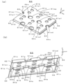
- FIG. 1A is a perspective view of the lid of the first embodiment, as viewed obliquely from above;
- FIG. 1B is a perspective view of the lid of the first embodiment, as viewed obliquely from below;
- 1 is an explanatory diagram of a manufacturing process of the capacitor according to the first embodiment;
- FIG. 10 is an explanatory diagram of the capacitor manufacturing process continuing from FIG.
- FIG. 11 is an explanatory diagram of the capacitor manufacturing process continuing from FIG.
- FIG. 12 is an explanatory diagram of the capacitor manufacturing process following FIG.
- FIG. 13 is a perspective view of a capacitor according to a second embodiment;
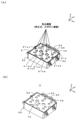
- FIG. 10A is a perspective view of a cover according to a second embodiment, as viewed obliquely from above;
- FIG. 10B is a perspective view of the cover according to the second embodiment, as viewed obliquely from below;
- 10A is a perspective view of a capacitor lid according to a third embodiment, as viewed obliquely from above;
- FIG. 10B is a perspective view of the lid according to the third embodiment, as viewed obliquely from below;
- FIG. 1A is a schematic diagram illustrating one modified example of a case and a lid;
- FIG. 1B is a schematic diagram illustrating another modified example of a case and a lid;
- FIG. 1C is a schematic diagram illustrating yet another modified example of a case and a lid.
- FIG. 1A is a schematic diagram illustrating one modified example of a top plate portion of a lid, and
- FIG. 1B is a schematic diagram illustrating another modified example of a top plate portion of a lid.
- the structure of the capacitor 1 of the first embodiment will be described with reference to Figures 1 to 8.
- the opening surface of the case 50 when the capacitor 1 is in a completed state is the xy-plane.
- the side surface on the short side of the case 50 is the yz-plane.
- the side surface on the long side of the case 50 is the zx-plane.
- the capacitor 1 and each of its components are illustrated.
- the capacitor 1 has a metallized film capacitor element (capacitor element), a first bus bar 20, a second bus bar 30, insulating paper, an insulating member 40 such as an insulating plate, a case 50, a lid 60, and a sealing resin 70.
- the capacitor element 10 has an element body 11, a first end surface electrode 12, and a second end surface electrode 13.
- the first end surface electrode 12 is formed by spraying a metal such as zinc onto a first end surface of the element body 11.
- the second end surface electrode 13 is formed by spraying a metal such as zinc onto a second end surface of the element body 11.
- the element body 11 is formed by stacking two metallized films each having aluminum vapor-deposited on a dielectric film, rolling or laminating the stacked metallized films, and pressing them into a flat shape. It should be noted that the element body 11 of this embodiment is not limited to this, and may be formed from a metallized film onto which other metals such as zinc or magnesium are vapor-deposited, or may be formed from a metallized film onto which multiple of these metals are vapor-deposited, or may be formed from a metallized film onto which an alloy of these metals is vapor-deposited.
- the first end surface electrode 12 and the first bus bar 20 are electrically connected by being soldered in contact with the first end surface electrode 12.
- the second end surface electrode 13 and the second bus bar 30 are electrically connected by being soldered in contact with the second end surface electrode 13.
- the first bus bar 20 and the second bus bar 30 are each formed of a conductive material such as copper.
- the first end surface electrode 12 and the first bus bar 20 are the P-pole side
- the second end surface electrode 13 and the second bus bar 30 are the N-pole side. It is also possible that the first end surface electrode 12 and the first bus bar 20 are the N-pole side
- the second end surface electrode 13 and the second bus bar 30 are the P-pole side.
- the capacitor 1 has one capacitor element 10, but is not limited to this and may have two or more capacitor elements 10.
- the first bus bar 20 is made of a conductive material such as copper, and has a shape shown in FIG.
- the first busbar 20 has a flat end surface electrode contact portion 21.
- the end surface electrode contact portion 21 comes into contact with the first end surface electrode 12 when the capacitor 1 is assembled.
- the end surface electrode contact portion 21 has a substantially rectangular outer shape in the xy plane.
- the end surface electrode contact portion 21 has two through portions 21a. Each through portion 21a has a rectangular shape in the xy plane.
- Each through portion 21a has a protrusion portion 21b that is used when soldering to the first end surface electrode 12.
- the first busbar 20 has a flat first lead portion 22.
- the first lead portion 22 extends from one side of the end surface electrode contact portion 21 (the side of the end surface electrode contact portion 21 on the y-axis positive side) in a direction perpendicular to the surface of the end surface electrode contact portion 21 (the z-axis positive direction).
- the first bus bar 20 has two second lead portions 23. Each second lead portion 23 extends in the positive direction of the z axis from an end portion of the first lead portion 22 opposite to the end surface electrode contact portion 21.
- the first busbar 20 has two external connection terminal portions 24.
- Each external connection terminal portion 24 extends from the end of the second pull-out portion 23 opposite the first pull-out portion 22 to the side facing the end surface electrode contact portion 21 in parallel to the end surface electrode contact portion 21 (in the negative y-axis direction).
- Each external connection terminal portion 24 has a through portion 24a.
- the through portion 24a is substantially circular in the xy plane view. The first busbar 20 and the external wiring are fastened together by the through portion 24a.
- the first busbar 20 is manufactured, for example, by using a mold to produce a flat plate having portions corresponding to the end electrode contact portion 21, the first lead portion 22, two second lead portions 23, and two external connection terminal portions 24, and then bending the plate.
- the second bus bar 30 is made of a conductive material such as copper, and has a shape shown in FIG.
- the second busbar 30 has a flat end surface electrode contact portion 31.
- the end surface electrode contact portion 31 comes into contact with the second end surface electrode 13 when the capacitor 1 is assembled.
- the end surface electrode contact portion 31 has a substantially rectangular outer shape in the xy plane.
- the end surface electrode contact portion 31 has a through portion 31a.
- Each through portion 31a has a rectangular shape in the xy plane.
- the through portion 31a has a protrusion 31b that is used when soldering to the second end surface electrode 13.
- the second busbar 30 has a flat first lead-out portion 32.
- the first lead-out portion 32 extends from one side of the end surface electrode contact portion 31 (the side of the end surface electrode contact portion 31 on the y-axis positive side) in a direction perpendicular to the surface of the end surface electrode contact portion 31 (the z-axis positive direction).
- the first pull-out portion 22 of the first busbar 20 and the first pull-out portion 32 of the second busbar 30 partially overlap in the zx plane view.
- the first pull-out portion 22 is located closer to the capacitor element 10 than the first pull-out portion 32.
- An insulating member 40 is disposed between the first pull-out portion 22 and the first pull-out portion 32. This ensures an insulating state between the first busbar 20 and the second busbar 30. Note that if an insulating state between the first busbar 20 and the second busbar 30 can be ensured, it is not necessary to dispose the insulating member 40 between the first pull-out portion 22 and the first pull-out portion 32.
- the second busbar 30 has two second pull-out portions 33.
- Each second pull-out portion 33 extends in the positive direction of the z-axis from the end of the first pull-out portion 32 opposite the end face electrode contact portion 31.
- the second busbar 30 has two external connection terminal portions 34.
- Each external connection terminal portion 34 extends from the end of the second pull-out portion 33 opposite the first pull-out portion 32 to the side facing the end surface electrode contact portion 31 in parallel to the end surface electrode contact portion 31 (in the negative y-axis direction).
- Each external connection terminal portion 34 has a through portion 34a.
- the through portion 34a is substantially circular in the xy plane view. The through portion 34a fastens the second busbar 30 to the external wiring.
- the second busbar 30 is manufactured, for example, by using a mold to produce a flat plate having portions corresponding to the end face electrode contact portion 31, the first pull-out portion 32, two second pull-out portions 33, and two external connection terminal portions 34, and then bending the plate.
- the insulating member 40 is formed from an insulating material. As shown in FIG. 6, the insulating member 40 has a substantially rectangular outer shape in the zx plane view. The insulating member 40 is disposed between the first pull-out portion 22 of the first bus bar 20 and the first pull-out portion 32 of the second bus bar 30, and insulates the first bus bar 20 from the second bus bar 30.
- the case 50 is formed from various materials, such as organic materials, such as resins and plastics, such as polyphenylene sulfide (PPS) and polybutylene terephthalate (PBT), and inorganic materials, such as ceramics.
- organic materials such as resins and plastics, such as polyphenylene sulfide (PPS) and polybutylene terephthalate (PBT), and inorganic materials, such as ceramics.
- PPS polyphenylene sulfide
- PBT polybutylene terephthalate
- the case 50 has the shape shown in Figures 7(a) and (b).
- the case 50 has a flat bottom 51a.
- the bottom 51a has a substantially rectangular outer diameter in an xy plane view.
- the case 50 also has a first side 51b, a second side 51c, a third side 51d, and a fourth side 51e.
- the first to fourth sides 51b to 51e are each flat extending from the four sides of the bottom 51a in a direction perpendicular to the inner surface (inner bottom surface) of the bottom 51a (positive direction of the z-axis).
- the case 50 is a rectangular box having an opening 51f that is open on the surface facing the inner bottom surface of the bottom 51a.
- the case 50 has two first mounting portions 52a and two second mounting portions 52b.
- the two first mounting portions 52a are arranged on the outer surface of the second side portion 51c.
- the two second mounting portions 52b are arranged on the outer surface of the fourth side portion 51e.
- Each of the first mounting portions 52a and each of the second mounting portions 52b has a through portion.
- the capacitor 1 is attached to an external device by the first mounting portions 52a and the second mounting portions 52b.
- the case 50 has two first fitted portions 53 on the inner surface of the second side portion 51c.
- Each first fitted portion 53 has a first lower fitted portion 53a and a first upper fitted portion 53b on the inner surface of the second side portion 51c.
- the first lower fitted portion 53a and the first upper fitted portion 53b are provided with a gap between them.
- the upper and lower surfaces of the first lower fitted portion 53a are parallel to the inner bottom surface of the bottom portion 51a.
- the first fitted portion 62 (see FIG. 8) of the lid 60 is fitted between the upper surface of the first lower fitted portion 53a and the lower surface of the first upper fitted portion 53b.
- the case 50 has two second fitted portions 54 on the inner surface of the fourth side portion 51e.
- Each second fitted portion 54 has a second lower fitted portion 54a and a second upper fitted portion 54b on the inner surface of the fourth side portion 51e.
- the second lower fitted portion 54a and the second upper fitted portion 54b are provided with a gap between them.
- the upper and lower surfaces of the second lower fitted portion 54a are parallel to the inner bottom surface of the bottom portion 51a.
- the second fitted portion 63 (see FIG. 8) of the lid 60 is fitted between the upper surface of the second lower fitted portion 54a and the lower surface of the second upper fitted portion 54b.
- the height of the upper surface of the two first lower fitted portions 53a is equal to the height of the upper surface of the two second lower fitted portions 54a. Also, the height of the lower surface of the two first upper fitted portions 53b is equal to the height of the lower surface of the two second upper fitted portions 54b.
- the case 50 is, for example, integrally formed with a bottom 51a, first to fourth side portions 51b to 51e, two first mounting portions 52a, two second mounting portions 52b, two first fitted portions 53, and two second fitted portions 54.
- the lid 60 is formed from various materials, such as organic materials, such as resins and plastics, such as polyphenylene sulfide (PPS) and polybutylene terephthalate (PBT), inorganic materials, such as ceramics, and metals, such as aluminum.
- organic materials such as resins and plastics, such as polyphenylene sulfide (PPS) and polybutylene terephthalate (PBT), inorganic materials, such as ceramics, and metals, such as aluminum.
- PPS polyphenylene sulfide
- PBT polybutylene terephthalate
- inorganic materials such as ceramics
- metals such as aluminum
- the lid 60 has a flat top plate 61a.
- the top plate 61a has a substantially rectangular outer shape in an xy plane view.
- the lid 60 also has a first side 61b, a second side 61c divided into two, a third side 61d, and a fourth side 61e divided into two.
- the first to fourth sides 61b to 61e are each flat and extend from each of the four edges of the top plate 61a in a direction perpendicular (negative z-axis direction) to the inner surface of the top plate 61a (negative z-axis surface).
- the top surface of the top plate 61a (outer surface of the lid) is a substantially flat surface.
- the top plate portion 61a has two large diameter through-holes 61aa, 61ab, four through-holes 61ac, 61ad, 61ae, twelve small diameter through-holes 61af, and a notch 61ag.
- Each of the large diameter through-holes 61aa, 61ab is circular in the xy plane.
- Each of the through-holes 61ac, 61ad, 61ae is semicircular in the xy plane.
- Each of the small diameter through-holes 61af is circular in the xy plane.
- the notch 61ag is rectangular in the xy plane.
- the through holes 61aa-61ae are mainly used for injecting the sealing resin 70.
- the through hole 61af is mainly used for releasing air bubbles generated during the injection of the sealing resin 70 to the outside of the resin.
- the diameters of the through holes 61aa, 61ab and the diameters of the through holes 61ac-61ae are larger than the diameter of the through hole 61af.
- the notch 61ag enables the first lead-out portion 22 of the first bus bar 20, the first lead-out portion 32 of the second bus bar 30, and the insulating member 40 to be drawn from inside the capacitor 1 to the outside of the capacitor 1 when the capacitor 1 is assembled (see FIG. 1).
- the number of through holes for injecting the sealing resin 70 may be a number other than six.
- the number of through holes for releasing air bubbles may be a number other than twelve.
- the lid 60 has two first fitting portions 62.
- Each first fitting portion 62 extends (in the positive direction of the x-axis) parallel to the top plate portion 61a from the end of the second side portion 61c, which is divided into two, opposite the top plate portion 61a.
- the thickness (thickness in the z-axis direction) of the first fitting portion 62 is approximately equal to the gap (distance in the z-axis direction) between the upper surface of the first lower fitted portion 53a and the lower surface of the first upper fitted portion 53b of the case 50.
- Each first fitting portion 62 is fitted between the upper surface of the first lower fitted portion 53a and the lower surface of the first upper fitted portion 53b.
- the lid 60 has two second fitting portions 63.
- the second fitting portions 63 extend (in the negative x-axis direction) parallel to the top plate portion 61a from the end of the fourth side portion 61e, which is divided into two, opposite the top plate portion 61a.
- the thickness (thickness in the z-axis direction) of the second fitting portions 63 is approximately equal to the gap (distance in the z-axis direction) between the upper surface of the second lower fitted portion 54a and the lower surface of the second upper fitted portion 54b of the case 50.
- Each second fitting portion 63 is fitted between the upper surface of the second lower fitted portion 54a and the lower surface of the second upper fitted portion 54b.
- the cover 60 has three extensions 64. Each extension 64 extends downward (in the negative z-axis direction) from the lower surface of the top plate 61a. Each extension 64 has the same shape.
- the first extension portion 64 (left side of FIG. 8(b)) has a base portion 64a, a first lower limit index portion 64b, and a second lower limit index portion 64c.
- the base portion 64a extends from the lower surface of the top plate portion 61a between the through portions 61ac and 61aa in a direction perpendicular to the lower surface of the top plate portion 61a (negative direction of the z-axis).
- the first lower limit index portion 64b extends from a lower portion of the side surface of the base portion 64a to a part of the through portion 61ac in the xy plane view.
- the second lower limit index portion 64c extends from a lower portion of the side surface of the base portion 64a to a part of the through portion 61aa in the xy plane view.
- the second extension portion 64 (center of FIG. 8(b)) has a base portion 64a, a first lower limit indicator portion 64b, and a second lower limit indicator portion 64c.
- the base portion 64a extends from the lower surface of the top plate portion 61a between the through portions 61aa and 61ab in a direction perpendicular to the lower surface of the top plate portion 61a (negative direction of the z-axis).
- the first lower limit indicator portion 64b extends from the lower portion of the side surface of the base portion 64a to a part of the through portion 61aa in the xy plane view.
- the second lower limit indicator portion 64c extends from the lower portion of the side surface of the base portion 64a to a part of the through portion 61ab in the xy plane view.
- the third extension portion 64 (right side of FIG. 8(b)) has a base portion 64a, a first lower limit index portion 64b, and a second lower limit index portion 64c.
- the base portion 64a extends from the lower surface of the top plate portion 61a between the through portions 61ab and 61ad in a direction perpendicular to the lower surface of the top plate portion 61a (negative direction of the z-axis).
- the first lower limit index portion 64b extends from a lower portion of the side surface of the base portion 64a to a part of the through portion 61ab in the xy plane view.
- the second lower limit index portion 64c extends from a lower portion of the side surface of the base portion 64a to a part of the through portion 61ad in the xy plane view.
- the upper surface (the surface on the positive side of the z-axis) of each first lower limit index portion 64b and the upper surface (the surface on the positive side of the z-axis) of each second lower limit index portion 64c are located lower (in the negative direction of the z-axis) than the lower surface of the top plate portion 61a.
- the upper surfaces of the first lower limit indicator portion 64b and the second lower limit indicator portion 64c of each extending portion 64 serve as indicators for the lower limit of the injection amount of the sealing resin 70.
- the first lower limit indicator portion 64b is visible from the through portion 61ac.
- the second lower limit indicator portion 64c is visible from the through portion 61aa.
- the first lower limit indicator portion 64b is visible from the through-hole 61aa
- the second lower limit indicator portion 64c is visible from the through-hole 61ab.
- the first lower limit indicator portion 64b is visible from the through-hole 61ab
- the second lower limit indicator portion 64c is visible from the through-hole 61ad.
- the upper surfaces of the first lower limit indicator portion 64b and the second lower limit indicator portion 64c of each extension portion 64 serve as indicators of the lower limit of the injection amount of the sealing resin 70, so that the extension portion 64 is embedded in the sealing resin after the sealing resin 70 is injected and hardened. Therefore, even if the lid 60 (the lower surface of the top plate portion 61a) and the resin surface of the sealing resin 70 are separated, at least the tip of the extension portion 64 is embedded in the sealing resin 70, so that heat can be dissipated from the sealing resin 70 via the extension portion 64.
- first to fourth side portions 61b to 61e as well as the first and second fitting portions 62 and 63 are in contact with the sealing resin 70. This allows heat to be dissipated from the sealing resin 70.
- the top surface of the top plate portion 61 a is used as an indicator of the upper limit of the injection amount of the sealing resin 70 .
- the cover 60 has a shape and dimensions such that it can cover substantially the entire opening 51 f of the case 50 .
- the lid 60 is, for example, integrally formed with a top plate portion 61a, first to fourth side portions 61b to 61e, two first fitting portions 62, two second fitting portions 63, and three extension portions 64.
- the sealing resin 70 seals the capacitor element 10, a portion of the first bus bar 20, a portion of the second bus bar 30, and a portion of the insulating member 40.
- the sealing resin 70 is, for example, an epoxy resin. Note that the sealing resin 70 is not limited to epoxy resin, and various insulating materials that are used as sealing resins for electronic components can be used. Note that the sealing resin 70 is formed by being injected into the case 50 in a liquid state and then cured.
- the insulating member 40 is attached to the surface on the negative side of the y-axis of the first pull-out portion 32 of the second busbar 30. This results in the state shown in FIG. 9(b).
- the second busbar 30 with the insulating member 40 attached is positioned so that the upper surface (the surface on the z-axis positive side) of the end surface electrode contact portion 31 is in contact with the second end surface electrode 13 of the capacitor element 10.
- the first busbar 20 is positioned so that the lower surface (the surface on the z-axis negative side) of the end surface electrode contact portion 21 is in contact with the first end surface electrode 12 of the capacitor element 10.
- the second busbar 30 is soldered to the second end surface electrode 13 using the protrusion 31b of the second busbar 30. This electrically connects the second busbar 30 and the second end surface electrode 13.
- the first busbar 20 is soldered to the first end surface electrode 12 using the protrusion 21b of the first busbar 20. This electrically connects the first busbar 20 and the first end surface electrode 12. This results in the state shown in FIG. 10(b).
- the unit in which the capacitor element 10, the first bus bar 20, the second bus bar 30, and the insulating member 40 are assembled as shown in FIG. 10(b) will be referred to as a wiring unit 5 as appropriate.
- the wiring unit 5 is placed into the case 50 through the opening 51f of the case 50.
- the lid 60 is then attached to the case 50. This results in the state shown in FIG. 11(b).
- sealing resin 70 such as liquid epoxy resin is injected through the through holes 61aa-61ae formed in the lid 60.
- the capacitor 1 shown in FIG. 12(b) is then completed by curing at a predetermined curing temperature.
- the sealing resin 70 is injected with the top surface of the top plate portion 61a of the lid 60 as an indicator of the upper limit of the amount of sealing resin 70 to be injected, and the top surfaces of the first and second lower limit indicator portions 64b, 64c (see FIG. 8) as indicators of the lower limit of the amount of sealing resin 70 to be injected.
- the top surface of the top plate portion 61a of the lid 60 is used as an indicator of the upper limit of the injection amount of the sealing resin 70, and the top surfaces of the first and second lower limit indicator portions 64b and 64c of the lid 60 are used as indicators of the lower limit of the injection amount of the sealing resin 70, and the injection amount of the sealing resin 70 is adjusted.
- This allows the thickness of the sealing resin 70 covering the upper part of the capacitor element 10 to be adjusted, and the variation in the amount of resin can be suppressed.
- the top surface of the top plate portion 61a of the lid 60 becomes the upper surface of the capacitor 1.
- the dimensional accuracy of the height of the upper surface of the capacitor 1 is improved because the dimensional accuracy of the height of the top surface of the top plate portion 61a is higher. This allows the required dimensional accuracy to be met, for example, even when a heat dissipation component is arranged on the upper surface of the capacitor 1. Furthermore, according to this embodiment, air bubbles that are generated between when the sealing resin 70 is injected and when the sealing resin 70 hardens are discharged from the through-holes 61aa to 61ae. This prevents air bubbles from accumulating between the resin surface of the sealing resin 70 and the lid 60. This prevents the sealing resin 70 from becoming thinner than expected.
- the extension portion 64 have indicator portions (first lower limit indicator portion 64b and second lower limit indicator portion 64c), the indicator (upper limit and/or lower limit) of the resin surface height can be set arbitrarily. In this embodiment, a lower limit of the resin surface height is set. Moreover, by providing an indicator portion on the extension portion 64, the indicator portion can be installed relatively easily even when there are restrictions on the size of the capacitor, compared to when an indicator portion is provided on the case.
- the top plate portion 61a of the lid 60 a substantially flat surface, the top plate portion 61a of the heat dissipation components can be easily and accurately positioned on the top surface.
- the lid 60 is also large enough to cover almost the entire opening 51f of the case 50. This increases the contact area between the top plate portion 61a of the lid 60 and the heat dissipation components placed on the top surface of the top plate portion 61a, improving the heat dissipation performance of the capacitor 1.
- the sealing resin 70 can be easily injected.
- the contact area between the top plate portion 61a and the heat dissipation components can be increased. This improves the heat dissipation performance of the capacitor 1.
- the manufacturing process of the capacitor 1 has been described in which the sealing resin 70 is injected into the case 50 after the lid 60 is attached to the case 50.
- the lid 60 may be attached to the case 50 after the sealing resin 70 is injected into the case 50.
- the case 50 has an indicator portion on the side.
- air bubbles generated between the injection of the sealing resin 70 and the hardening of the sealing resin 70 are discharged from the through-holes 61aa to 61ae. Therefore, air bubbles are prevented from accumulating between the resin surface of the sealing resin 70 and the lid 60. This prevents the sealing resin 70 from becoming thinner than expected.
- the lid 60 may be attached to the case 50 before the sealing resin 70 is completely cured. In this case as well, it is possible to prevent the sealing resin 70 from becoming thinner than expected.
- the capacitor 1A of the second embodiment will be described in detail below with reference to Figures 13 and 14.
- the capacitor 1A differs from the capacitor 1 of the first embodiment in that it has a lid 60A that is different from the lid 60 of the capacitor 1.
- the lid 60A will be mainly described.
- the other components (first bus bar 20, second bus bar 30, insulating member 40, case 50) of the capacitor 1A and the capacitor 1 have the same structure, and therefore in the second embodiment, the same reference numerals are used and the description will be omitted.
- the cover 60A has a top plate portion 61aA, first to fourth side portions 61b to 61e, two first fitting portions 62, two second fitting portions 63, and three extension portions 64.
- the top surface of the top plate portion 61aA is a substantially flat surface.
- the top plate portion 61aA has two circular through-portions 61aa, 61ab, four semicircular through-portions 61ac to 61ae, and nine circular through-portions 61af.
- the through holes 61aa to 61ae are mainly used for injecting the sealing resin 70.
- the through hole 61af is mainly used for releasing air bubbles generated during the injection of the sealing resin 70 to the outside of the resin.
- the diameters of the through holes 61aa, 61ab and the diameters of the through holes 61ac to 61ae are larger than the diameter of the through hole 61af.
- the top plate portion 61a in the first embodiment has twelve through-holes 61af, whereas the top plate portion 61aA in the present embodiment has nine through-holes 61af. Also, the top plate portion 61a in the first embodiment has a notch portion 61ag, whereas the top plate portion 61aA in the present embodiment has no notch portion.
- the number of through-holes for injecting the sealing resin 70 may be a number other than six.
- the number of through-holes for releasing air bubbles may be a number other than nine.
- the lid 60 in the first embodiment has a shape and dimensions that cover substantially the entire opening 51f of the case 50.
- the lid 60A in this embodiment has a shape and dimensions that cover only a portion of the opening 51f of the case 50, rather than substantially the entire opening 51f. Specifically, the portion of the opening 51f indicated by the dotted arrow 80 is not covered by the lid 60A.
- the second embodiment provides the same effects as the first embodiment. Furthermore, the second embodiment allows the lid 60A to suppress variation in the amount of resin in the sealing resin, while allowing more freedom in configuring the drawers of the first bus bar 20 and the second bus bar 30, etc., by using the portions not covered by the lid 60A.
- the capacitor of the third embodiment will be described in detail below with reference to Fig. 15.
- the capacitor of the third embodiment differs from the capacitor 1 of the first embodiment in that it has a lid 60B that is different from the lid 60.
- the lid 60B will be mainly described.
- the other components (first bus bar 20, second bus bar 30, insulating member 40, case 50) have the same structure in the capacitor of the third embodiment and the capacitor 1 of the first embodiment, and description and illustration of the other components will be omitted in the third embodiment.
- the lid 60B of this embodiment has a structure in which the extension portion 64 is removed from the lid 60 of the first embodiment.
- the lid 60B has a top plate portion 61a, first to fourth side portions 61b to 61e, two first fitting portions 62, and two second fitting portions 63.
- the top plate portion 61a has, in an xy plan view, two circular through-portions 61aa, 61ab, four semicircular through-portions 61ac to 61ae, twelve circular through-portions 61af, and a rectangular cutout portion 61ag.
- the through-holes 61aa to 61ae are mainly used for injecting the sealing resin 70.
- the through-hole 61af is mainly used for releasing air bubbles generated during the injection of the sealing resin 70 to the outside of the resin.
- the diameters of the through-holes 61aa, 61ab and the diameters of the through-holes 61ac to 61ae are larger than the diameter of the through-hole 61af.
- the notch 61ag enables the first lead-out portion 22 of the first bus bar 20, the first lead-out portion 32 of the second bus bar 30, and the insulating member 40 to be drawn from inside the capacitor to the outside of the capacitor when the capacitor 1 is assembled.
- the number of the through-holes for injecting the sealing resin 70 may be a number other than six.
- the number of the through-holes for releasing air bubbles may be a number other than twelve.
- the top surface of the top plate portion 61a of the lid 60B is used as an indicator of the upper limit of the injection amount of the sealing resin 70
- the bottom surface of the top plate portion 61a is used as an indicator of the lower limit of the injection amount of the sealing resin 70.
- the thickness of the lid 60B is adjusted.
- the cover 60B of the third embodiment adjusts the amount of sealing resin 70 injected by using the top surface of the top plate portion 61a as an indicator of the upper limit of the amount of sealing resin 70 injected and the bottom surface of the top plate portion 61a as an indicator of the lower limit of the amount of sealing resin 70 injected. This makes it possible to adjust the thickness of the sealing resin 70 that covers the top of the capacitor element 10, and suppresses variation in the amount of resin. It also provides the same effects as the first embodiment.
- the resin surface of the sealing resin 70 contacts the lower surface of the top plate portion 61a.
- contact between the lower surface of the top plate portion 61a and the sealing resin 70 is not essential.
- the resin surface of the sealing resin 70 visible from the penetration portion of the lid 60B reaching close to the lower surface of the top plate portion 61a is also included in the lid 60B (penetration portion) functioning as an indicator portion.
- the lids 60, 60A, and 60B are fitted inside the first to fourth side portions 51b to 51e of the case 50, but are not limited thereto.
- the case may be fitted inside the first to fourth side portions of the lid.
- the outer surface of the second side portion of the case has a first fitted portion
- the outer surface of the fourth side portion of the case has a second fitted portion.
- the lid has a first fitted portion extending from the lower end of the second side portion in parallel with the top plate portion, and a second fitted portion extending from the lower end of the fourth side portion in parallel with the top plate portion.
- the lids 60, 60A, 60B fit inside the first to fourth side portions 51b to 51e of the case 50, but are not limited to this.
- they may be as shown in Figures 16(a) to 16(c).
- Figures 16(a) to 16(c) are schematic top views of the capacitor, and for simplicity of illustration, the first bus bar 20, second bus bar 30, insulating member 40, etc. are omitted.
- the top plate portion 61aC of the lid 60C of the modified example shown in Figure 16(a) has through-holes 61aaC to 61aeC for injecting resin, a through-hole 61afC for releasing air bubbles, and a notch 61agC for pulling the first bus bar 20, the second bus bar 30, and the insulating member 40 to the outside of the capacitor 1.
- the lid 60C has an outer shape that covers almost the entire opening 51fC of the case 50C.
- the first to fourth side portions 51bC to 51eC of the case 50C fit inside the first to fourth side portions 61bC to 61eC of the lid 60C.
- the outer surface of the second side portion 51cC of the case 50C has a first mating portion
- the second side portion 61cC of the lid 60C has a first mating portion extending from the lower end in parallel to the top plate portion 61aC.
- the first mating portion mates with the first mating portion
- the outer surface of the fourth side portion 51eC of the case 50C has a second mating portion
- the fourth side portion 61eC of the lid 60C has a second mating portion extending from the lower end in parallel to the top plate portion 61aC.
- the second mating portion mates with the second mating portion.
- the top plate portion 61aD of the lid 60D of the modified example shown in Figure 16 (b) has through-holes 61aaD-61adD for injecting resin and a through-hole 61afD for releasing air bubbles.
- the lid 60D has a rectangular shape.
- the lid 60D covers only a portion of the opening 51fD of the case 50D, not substantially the entirety of it. In other words, the portion of the opening 51fD indicated by the dotted arrow 80D is not covered by the lid 60D.
- the second and fourth side portions 51cD, 51eD of the case 50D fit inside the second and fourth side portions 61cD, 61eD of the lid 60D.
- the outer surface of the second side 51cD of the case 50D has a first mating portion
- the second side 61cD of the lid 60D has a first mating portion extending from the bottom end in parallel to the top plate 61aD.
- the first mating portion mates with the first mating portion
- the outer surface of the fourth side 51eD of the case 50D has a second mating portion
- the fourth side 61eD of the lid 60D has a second mating portion extending from the bottom end in parallel to the top plate 61aD.
- the second mating portion mates with the second mating portion.
- the top plate portion 61aE of the lid 60E of the modified example shown in Figure 16 (c) has through-holes 61aaE-61adE for injecting resin and a through-hole 61afE for releasing air bubbles.
- the lid 60E has a cross shape.
- the lid 60E covers only a portion of the opening 51fE of the case 50E, not substantially the entirety of it. In other words, the portion of the opening 51fE indicated by the dotted arrow 80E is not covered by the lid 60E.
- the first to fourth side portions 51bE-51eE of the case 50E fit inside the first to fourth side portions 61bE-61eE of the lid 60E.
- the outer surface of the second side portion 51cE of the case 50E has a first fitted portion
- the second side portion 61cE of the lid 60E has a first fitted portion extending from the lower end in parallel with the top plate portion 61aE.
- the first fitted portion fits into the first fitted portion
- the outer surface of the fourth side portion 51eE of the case 50E has a second fitted portion
- the fourth side portion 61eE of the lid 60E has a second fitted portion extending from the lower end in parallel with the top plate portion 61aE.
- the second fitted portion fits into the second fitted portion.
- the outer surface of the first side portion 51bE of the case 50E has a third fitted portion
- the first side portion 61bE of the lid 60E has a third fitted portion extending from the lower end in parallel with the top plate portion 61aE.
- the third fitting portion fits into the third fitted portion
- the outer surface of the third side portion 51dE of the case 50E has a fourth fitted portion
- the third side portion 61dE of the lid 60E has a fourth fitted portion that extends from the lower end in parallel with the top plate portion 61aE.
- the fourth fitting portion fits into the fourth fitted portion.
- the top plate portion 61a of the lids 60, 60A, 60B in the first to third embodiments has a flat plate shape, but is not limited to this. For example, it may have the shape shown in Figures 17(a) and 17(b).
- Figures 17(a) and 17(b) are schematic cross-sectional views of a capacitor. To simplify the illustration, the first bus bar 20, the second bus bar 30, the insulating member 40, and the like are omitted from the illustration.
- the top plate portion 61aF of the lid 60F of the modified example shown in FIG. 17(a) has through holes 61aaF-61adF for resin injection.
- the top plate portion 61aF of the lid 60F also has an extension portion 64F having a base portion 64aF, a first lower limit index portion 64bF, and a second lower limit index portion 64cF at three locations on the underside.
- the heights of the upper surfaces of the three first lower limit index portions 64bF and the upper surfaces of the three second lower limit index portions 64cF are equal.
- the upper surfaces of the three first lower limit index portions 64bF and the upper surfaces of the three second lower limit index portions 64cF serve as lower limit indicators for the amount of sealing resin 70 to be injected.
- the upper surface near the deepest portion of the top plate portion 61aF of the lid 60F serves as an upper limit indicator for the amount of sealing resin 70 to be injected.
- the top plate portion 61aF of the lid 60F has a curved shape that bulges outward from the capacitor.
- the tip of the extension portion 64F is embedded in the sealing resin 70.
- the top plate portion 61aG of the lid 60G of the modified example shown in FIG. 17(b) has through-holes 61aaG-61adG for resin injection.
- the top plate portion 61aG of the lid 60G also has an extension portion 64G having a base portion 64aG, a first lower limit index portion 64bG, and a second lower limit index portion 64cG at three locations on the underside.
- the heights of the upper surfaces of the three first lower limit index portions 64bG and the upper surfaces of the three second lower limit index portions 64cG are equal.
- the upper surfaces of the three first lower limit index portions 64bG and the upper surfaces of the three second lower limit index portions 64cG serve as lower limit indicators for the amount of sealing resin 70 to be injected.
- the upper surface near the deepest portion of the top plate portion 61aG of the lid 60G serves as an upper limit indicator for the amount of sealing resin 70 to be injected.
- the top plate portion 61aG of the lid 60G is curved and recessed toward the inside of the capacitor.
- the tip of the extension portion 64G is embedded in the sealing resin 70.
- the top plate portions 61aC to 61aE may have a curved shape that bulges outward from the capacitor, or may have a curved shape that is recessed inward from the capacitor.
- the present invention is widely applicable to capacitors in which a capacitor element is housed in a case and sealed with a sealing resin.
- Capacitor 10 Capacitor element 20: First bus bar 30: Second bus bar 40: Insulating member 50: Case 53: First fitted portion 53a: First lower fitted portion 53b: First upper fitted portion 54: Second fitted portion 54a: Second lower fitted portion 54b: Second upper fitted portion 60: Lid 61a: Top plate portion 61aa to 61af: Through portion 62: First fitting portion 63: Second fitting portion 64: Index portion 64b: First lower limit index portion 64c: Second lower limit index portion 70: Sealing resin
Landscapes
- Engineering & Computer Science (AREA)
- Power Engineering (AREA)
- Microelectronics & Electronic Packaging (AREA)
- Fixed Capacitors And Capacitor Manufacturing Machines (AREA)
Priority Applications (3)
| Application Number | Priority Date | Filing Date | Title |
|---|---|---|---|
| CN202480005802.3A CN120390970A (zh) | 2023-03-23 | 2024-02-02 | 电容器以及电容器的制造方法 |
| EP24774463.4A EP4685831A1 (en) | 2023-03-23 | 2024-02-02 | Capacitor and method for manufacturing capacitor |
| JP2025508186A JPWO2024195317A1 (https=) | 2023-03-23 | 2024-02-02 |
Applications Claiming Priority (2)
| Application Number | Priority Date | Filing Date | Title |
|---|---|---|---|
| JP2023046239 | 2023-03-23 | ||
| JP2023-046239 | 2023-03-23 |
Publications (1)
| Publication Number | Publication Date |
|---|---|
| WO2024195317A1 true WO2024195317A1 (ja) | 2024-09-26 |
Family
ID=92841269
Family Applications (1)
| Application Number | Title | Priority Date | Filing Date |
|---|---|---|---|
| PCT/JP2024/003410 Ceased WO2024195317A1 (ja) | 2023-03-23 | 2024-02-02 | コンデンサ及びコンデンサの製造方法 |
Country Status (4)
| Country | Link |
|---|---|
| EP (1) | EP4685831A1 (https=) |
| JP (1) | JPWO2024195317A1 (https=) |
| CN (1) | CN120390970A (https=) |
| WO (1) | WO2024195317A1 (https=) |
Citations (3)
| Publication number | Priority date | Publication date | Assignee | Title |
|---|---|---|---|---|
| WO2019155581A1 (ja) * | 2018-02-08 | 2019-08-15 | 日立化成株式会社 | フィルムコンデンサ |
| JP2022085707A (ja) * | 2020-11-27 | 2022-06-08 | 古河電池株式会社 | 液式鉛蓄電池 |
| JP2022100801A (ja) | 2020-12-24 | 2022-07-06 | ニチコン株式会社 | コンデンサ用ケースおよびフィルムコンデンサ |
-
2024
- 2024-02-02 CN CN202480005802.3A patent/CN120390970A/zh active Pending
- 2024-02-02 EP EP24774463.4A patent/EP4685831A1/en active Pending
- 2024-02-02 WO PCT/JP2024/003410 patent/WO2024195317A1/ja not_active Ceased
- 2024-02-02 JP JP2025508186A patent/JPWO2024195317A1/ja active Pending
Patent Citations (3)
| Publication number | Priority date | Publication date | Assignee | Title |
|---|---|---|---|---|
| WO2019155581A1 (ja) * | 2018-02-08 | 2019-08-15 | 日立化成株式会社 | フィルムコンデンサ |
| JP2022085707A (ja) * | 2020-11-27 | 2022-06-08 | 古河電池株式会社 | 液式鉛蓄電池 |
| JP2022100801A (ja) | 2020-12-24 | 2022-07-06 | ニチコン株式会社 | コンデンサ用ケースおよびフィルムコンデンサ |
Non-Patent Citations (1)
| Title |
|---|
| See also references of EP4685831A1 |
Also Published As
| Publication number | Publication date |
|---|---|
| JPWO2024195317A1 (https=) | 2024-09-26 |
| CN120390970A (zh) | 2025-07-29 |
| EP4685831A1 (en) | 2026-01-28 |
Similar Documents
| Publication | Publication Date | Title |
|---|---|---|
| EP2107864B1 (en) | Control device | |
| JP4450378B2 (ja) | 表面実装型コンデンサ及びその製造方法 | |
| JP4552676B2 (ja) | ケースモールド型コンデンサの製造方法 | |
| US7259502B2 (en) | Insert terminal-containing case, piezoelectric electroacoustic transducer using the same, and process for producing insert terminal-containing case | |
| JP5233294B2 (ja) | 電子部品 | |
| CN109997207B (zh) | 电容器 | |
| WO2024195317A1 (ja) | コンデンサ及びコンデンサの製造方法 | |
| CN116646176A (zh) | 电子零件 | |
| JP5574613B2 (ja) | 回路装置 | |
| US12417880B2 (en) | Electronic device having first and second metal terminals | |
| CN116830223A (zh) | 电容器、电容器模块以及电容器模块的制造方法 | |
| JP7757229B2 (ja) | ケースモールド型フィルムコンデンサ | |
| CN115298781A (zh) | 电容器及其制造方法 | |
| WO2025099981A1 (ja) | コンデンサ | |
| JP4991501B2 (ja) | 固体電解コンデンサ | |
| US12278055B2 (en) | Electronic component | |
| CN112956016A (zh) | 驱动器 | |
| JP2024154829A (ja) | コンデンサ | |
| JP2024108711A (ja) | コンデンサ | |
| JP2019009179A (ja) | コンデンサおよびコンデンサの製造方法 | |
| JP2025012632A (ja) | コンデンサ | |
| JP2024168448A (ja) | コンデンサ | |
| CN121794777A (zh) | 电容器 | |
| JP2022051449A (ja) | コンデンサの製造方法 | |
| JP2560226Y2 (ja) | チップ型コンデンサ |
Legal Events
| Date | Code | Title | Description |
|---|---|---|---|
| 121 | Ep: the epo has been informed by wipo that ep was designated in this application |
Ref document number: 24774463 Country of ref document: EP Kind code of ref document: A1 |
|
| WWE | Wipo information: entry into national phase |
Ref document number: 202480005802.3 Country of ref document: CN |
|
| ENP | Entry into the national phase |
Ref document number: 2025508186 Country of ref document: JP Kind code of ref document: A |
|
| WWE | Wipo information: entry into national phase |
Ref document number: 2025508186 Country of ref document: JP |
|
| WWP | Wipo information: published in national office |
Ref document number: 202480005802.3 Country of ref document: CN |
|
| WWE | Wipo information: entry into national phase |
Ref document number: 2024774463 Country of ref document: EP |
|
| NENP | Non-entry into the national phase |
Ref country code: DE |
|
| ENP | Entry into the national phase |
Ref document number: 2024774463 Country of ref document: EP Effective date: 20251023 |
|
| ENP | Entry into the national phase |
Ref document number: 2024774463 Country of ref document: EP Effective date: 20251023 |
|
| ENP | Entry into the national phase |
Ref document number: 2024774463 Country of ref document: EP Effective date: 20251023 |
|
| ENP | Entry into the national phase |
Ref document number: 2024774463 Country of ref document: EP Effective date: 20251023 |
|
| ENP | Entry into the national phase |
Ref document number: 2024774463 Country of ref document: EP Effective date: 20251023 |
|
| ENP | Entry into the national phase |
Ref document number: 2024774463 Country of ref document: EP Effective date: 20251023 |