WO2024195230A1 - ピアス機構及びこれを備えた自動分析装置 - Google Patents
ピアス機構及びこれを備えた自動分析装置 Download PDFInfo
- Publication number
- WO2024195230A1 WO2024195230A1 PCT/JP2023/045333 JP2023045333W WO2024195230A1 WO 2024195230 A1 WO2024195230 A1 WO 2024195230A1 JP 2023045333 W JP2023045333 W JP 2023045333W WO 2024195230 A1 WO2024195230 A1 WO 2024195230A1
- Authority
- WO
- WIPO (PCT)
- Prior art keywords
- needle
- reagent
- piercing mechanism
- holder
- needle holder
- Prior art date
- Legal status (The legal status is an assumption and is not a legal conclusion. Google has not performed a legal analysis and makes no representation as to the accuracy of the status listed.)
- Ceased
Links
Images







Classifications
-
- G—PHYSICS
- G01—MEASURING; TESTING
- G01N—INVESTIGATING OR ANALYSING MATERIALS BY DETERMINING THEIR CHEMICAL OR PHYSICAL PROPERTIES
- G01N35/00—Automatic analysis not limited to methods or materials provided for in any single one of groups G01N1/00 - G01N33/00; Handling materials therefor
- G01N35/10—Devices for transferring samples or any liquids to, in, or from, the analysis apparatus, e.g. suction devices, injection devices
- G01N35/1079—Devices for transferring samples or any liquids to, in, or from, the analysis apparatus, e.g. suction devices, injection devices with means for piercing stoppers or septums
-
- G—PHYSICS
- G01—MEASURING; TESTING
- G01N—INVESTIGATING OR ANALYSING MATERIALS BY DETERMINING THEIR CHEMICAL OR PHYSICAL PROPERTIES
- G01N35/00—Automatic analysis not limited to methods or materials provided for in any single one of groups G01N1/00 - G01N33/00; Handling materials therefor
- G01N35/10—Devices for transferring samples or any liquids to, in, or from, the analysis apparatus, e.g. suction devices, injection devices
- G01N35/1002—Reagent dispensers
-
- G—PHYSICS
- G01—MEASURING; TESTING
- G01N—INVESTIGATING OR ANALYSING MATERIALS BY DETERMINING THEIR CHEMICAL OR PHYSICAL PROPERTIES
- G01N35/00—Automatic analysis not limited to methods or materials provided for in any single one of groups G01N1/00 - G01N33/00; Handling materials therefor
- G01N35/10—Devices for transferring samples or any liquids to, in, or from, the analysis apparatus, e.g. suction devices, injection devices
- G01N35/1009—Characterised by arrangements for controlling the aspiration or dispense of liquids
- G01N35/1011—Control of the position or alignment of the transfer device
-
- G—PHYSICS
- G01—MEASURING; TESTING
- G01N—INVESTIGATING OR ANALYSING MATERIALS BY DETERMINING THEIR CHEMICAL OR PHYSICAL PROPERTIES
- G01N35/00—Automatic analysis not limited to methods or materials provided for in any single one of groups G01N1/00 - G01N33/00; Handling materials therefor
- G01N2035/00178—Special arrangements of analysers
- G01N2035/00277—Special precautions to avoid contamination (e.g. enclosures, glove- boxes, sealed sample carriers, disposal of contaminated material)
Definitions
- the present invention relates to an automatic analyzer that analyzes specimens, which are liquid samples such as blood and urine, and a piercing mechanism used in the automatic analyzer.
- a pierce mechanism has been proposed that has a mechanism that allows the needle holder, through which the needle moves in and out, to shift horizontally (Patent Document 1).
- Patent Document 1 a mechanism that allows the needle holder, through which the needle moves in and out, to shift horizontally.
- the needle holder is guided in the process of lowering by a funnel-shaped recess formed on the top surface of the lid, and shifts horizontally to become centered.
- the needle protrudes from the needle holder that has been centered in this way, forming a cut with high precision in the center of the lid.
- the object of the present invention is to provide a piercing mechanism that can form a cut in the desired position range of the lid of a reagent bottle even when the tip of the needle holder is close to the edge of the lid from the recess of the lid of the reagent bottle, and an automatic analyzer equipped with the same.
- the present invention provides a piercing mechanism that includes a needle and a cylindrical needle holder through which the needle passes and that holds the needle slidably in the axial direction, the needle holder is placed against a reagent bottle placed in an automatic analyzer, the needle is pushed out from the needle holder, and the needle pierces the reagent bottle to form a cut, the needle protruding radially outward and having a protruding portion on its outer circumferential surface that slides against the inner circumferential surface of the needle holder, the protruding portion having a shape that makes point contact with the inner circumferential surface of the needle holder when viewed in a cross section cut along a plane passing through the center line of the needle, and the needle is freely tiltable relative to the needle holder.
- FIG. 13 is a diagram showing the state of inserting a reagent probe into a reagent bottle when a notch is formed in a position offset from the center of the reagent bottle lid.
- FIG. 1 is a diagram showing a configuration for raising and lowering a piercing mechanism in an automatic analyzer according to an embodiment of the present invention.
- FIG. 1 is a schematic diagram of a piercing mechanism provided in an automatic analyzer according to an embodiment of the present invention.
- FIG. 1 is a cross-sectional view including a central axis of an assembly of a needle holder and a needle provided in an automatic analyzer according to an embodiment of the present invention.
- FIG. 1 is a diagram showing a configuration for raising and lowering a piercing mechanism in an automatic analyzer according to an embodiment of the present invention.
- FIG. 1 is a schematic diagram of a piercing mechanism provided in an automatic analyzer according to an embodiment of the present invention.
- FIG. 1 is a cross-sectional view
- FIG. 1 is a perspective cross-sectional view of a main part of an assembly of a needle holder and a needle provided in an automatic analyzer according to an embodiment of the present invention
- FIG. 10 is an enlarged view of part A in FIG.
- FIG. 1 is an explanatory diagram of how a needle tilt mechanism provided in an automatic analyzer according to an embodiment of the present invention functions.
- FIG. 1 is an explanatory diagram of how a needle tilt mechanism provided in an automatic analyzer according to an embodiment of the present invention functions.
- FIG. 1 is a schematic diagram showing a main part of a first modified needle provided in an automatic analyzer according to an embodiment of the present invention
- FIG. 1 is a schematic diagram showing a main part of a second modified needle provided in an automatic analyzer according to an embodiment of the present invention;
- FIG. 13 is a schematic diagram showing a main part of a third modified needle provided in the automatic analyzer according to the embodiment of the present invention
- FIG. 13 is a schematic diagram showing a main part of a fourth modified needle provided in the automatic analyzer according to the embodiment of the present invention
- FIG. 13 is a schematic diagram showing a main part of a fifth modified example of a needle provided in an automatic analyzer according to an embodiment of the present invention.
- FIG. 13 is a perspective cross-sectional view of a main part of an assembly of a needle holder and a needle according to a comparative example;
- Fig. 1 is a schematic diagram of an automatic analyzer according to an embodiment of the present invention.
- the automatic analyzer shown in Fig. 1 is an apparatus for dispensing a specimen, which is a biological sample such as blood or urine, and a reagent into a reaction cell (reaction vessel) 2, respectively, for reaction, and measuring the components of the reaction solution of the specimen and the reagent to analyze the specimen.
- a specimen which is a biological sample such as blood or urine
- reaction vessel reaction vessel
- reagent dispensing mechanisms 7 and 8 are installed, which can rotate and move up and down like the sample dispensing mechanism 11.
- the reagent dispensing mechanisms 7 and 8 are equipped with reagent probes 7a and 8a, respectively.
- Reagent syringes (not shown) are connected to the reagent probes 7a and 8a.
- the reagent probes 7a and 8a move up and down while moving between the suction cassette 111 and the reaction cell 2, tracing an arc trajectory around each rotation axis of the reagent dispensing mechanisms 7 and 8, accessing the inside of the reagent storage 9 from the suction cassette 111 and dispensing reagent from the reagent bottle 10 into the reaction cell 2.
- a cleaning mechanism 3, a light source 4a, a spectrophotometer 4, and stirring mechanisms 5 and 6 are arranged around the reaction disk 1.
- a cleaning pump (not shown) is connected to the cleaning mechanism 3.
- Washing tanks 32, 33, 13, 30, and 31 are installed on the flow paths of the reagent dispensing mechanisms 7 and 8, the sample dispensing mechanism 11, and the stirring mechanisms 5 and 6, respectively.
- the sample container 15 contains a sample, and is placed on a rack 16 and transported by the sample transport line 17.
- each device such as the sample transport line 17, reaction disk 1, reagent storage 9, cleaning mechanism 3, light source 4a, spectrophotometer 4, stirring mechanisms 5 and 6, and reagent autoloader mechanism 100, is electrically connected to a controller (not shown).
- the controller is configured to include a computer, etc., and controls the operation of each device mounted on the automatic analyzer, as well as performs calculations to determine the concentration of a specific component in the sample.
- a rack 16 carrying sample containers 15 is transported to the vicinity of the reaction disk 1 (the operating range of the sample probe 11a) by the sample transport line 17.
- the samples inside the sample containers 15 carried on the rack 16 are aspirated by the sample probe 11a by the sample dispensing mechanism 11, transported onto the reaction disk 1, and dispensed into the reaction cells 2.
- a reagent bottle 10 containing a reagent to be used in analyzing the specimen is transported within the reagent storage 9 into the operating range of the reagent probe 7a or 8a.
- the reagent inside this reagent bottle 10 is sucked into the reagent probe 7a or 8a by the reagent dispensing mechanism 7 or 8, transported onto the reaction disk 1, and dispensed into the reaction cell 2 containing the specimen.
- the mixture of specimen and reagent dispensed into the same reaction cell 2 is stirred by the stirring mechanism 5.
- the spectrophotometer 4 The luminosity measured by the spectrophotometer 4 is converted into a digital signal by an A/D converter (not shown) and transmitted from the spectrophotometer 4 to the controller via an interface.
- the concentration of a specific component in the sample is calculated based on the measurement value input from the spectrophotometer 4, and the calculation result is displayed on a display device (not shown) as the analysis result or recorded in a memory unit (not shown).
- FIG. 2 is a schematic diagram showing the configuration of the reagent autoloader mechanism 100.
- the reagent probes 7a and 8b are inserted into the opening of the reagent bottle 10 to aspirate the reagent, and the reagent bottle 10 has a lid 112 attached to the opening to seal the inside.
- a cut for inserting the reagent probes 7a and 7b is formed in the lid 112 of the reagent bottle 10.
- the cut formed in the lid 112 is small and is closed when the reagent probes 7a and 7b are not inserted, so that the contact between the reagent inside the reagent bottle 10 and the outside air is suppressed, and deterioration of the reagent is suppressed.
- a cut is formed in the lid 112 of the reagent bottle 10 and the reagent is automatically stored inside the reagent storage 9.
- the reagent bottle 10 is opened and transported to the reagent storage 9 by the reagent autoloader mechanism 100.
- the reagent autoloader mechanism 100 is disposed on top of the reagent storage cabinet 9 as shown in FIG. 2.
- This reagent autoloader mechanism 100 comprises a reagent tray 103, tray rails 102, reagent transport mechanism 101, needle washing tank 108, needle drying port 109, support 117, and metal plate 118.
- Each mechanism such as the reagent tray 103, tray rails 102, reagent transport mechanism 101, needle washing tank 108, and needle drying port 109, is attached to a single metal plate 118.
- the reagent tray 103 is where the operator places the reagent bottles 10 when loading the reagent bottles 10 into the automated analyzer.
- the reagent tray 103 is guided by the tray rails 102 and moves in the vertical direction in FIG. 2 along linear rails 119.
- the range of movement of the reagent tray 103 is limited to the range where it overlaps with the metal plate 118 in a plan view so that the reagent autoloader mechanism 100 fits into the automated analyzer.
- the reagent tray 103 has bottle slots (not shown) arranged in a straight line, in which multiple reagent bottles 10 are placed, and a reagent bottle 10 is placed in each of these bottle slots.
- the reagent transport mechanism 101 is a mechanism that transports the reagent bottles 10 placed on the reagent tray 103 into the inside of the reagent storage cabinet 9.
- the reagent transport mechanism 101 includes a reagent bottle gripping mechanism (not shown) that grips the reagent bottle 10, and a piercing mechanism (reagent bottle opener) 200 that forms a cut in the lid 112 of the reagent bottle 10.
- the reagent bottle gripping mechanism moves along a fixed frame 106 extending in a direction perpendicular to the tray rail 102 (left-right direction in FIG. 2) and moves between the reagent tray 103 and the reagent slot 113.
- the fixed frame 106 is supported by a base 131.
- the reagent bottle gripping mechanism is equipped with a claw (not shown) for gripping the reagent bottle 10, and the reagent bottle gripping mechanism grips the reagent bottle 10 by hooking this claw onto the reagent bottle 10.
- the reagent slot 113 is an opening and closing cover that prevents the cool air from escaping from the inside of the refrigerated reagent storage 9, and is normally closed except when the reagent bottle 10 is transported into and out of the reagent storage 9.
- the reagent slot 113 opens, and the reagent bottle 10 is transported in and out of the reagent storage 9.
- the piercing mechanism 200 moves along the fixed frame 106 together with the reagent transport mechanism.
- a needle 250 (FIG. 7) for cutting the lid 112 of the reagent bottle 10 is attached to the piercing mechanism 200.
- the needle washing tank 108 and the needle drying port 109 are arranged on the operating line of the piercing mechanism 200.
- the tip of the needle 250 (piercing needle 251) (FIG. 8) that is inserted into the reagent bottle 10 to cut the lid 112 is washed with washing water in the needle washing tank 108, and the washing water is removed at the needle drying port 109.
- the tip of the needle 250 is kept clean and washing water is prevented from being brought into the reagent bottle 10 and diluting the reagent.
- Reagent bottle delivery The following describes the operation of the reagent autoloader mechanism 100 configured as described above to load the reagent bottle 10 into the reagent storage cabinet 9. The following operation is realized by the controller controlling each mechanism.
- the operator When the reagent bottle 10 is carried into the reagent storage 9, the operator first operates the button switch (not shown) of the automatic analyzer for the first time.
- the controller recognizes the first operation of the button switch, the controller controls the reagent tray 103 to move from the standby position along the tray rail 102 to the insertion position for the reagent bottle 10 (e.g., the lower side in FIG. 2).
- the operator places the reagent bottle 10 on the reagent tray 103 that has arrived at the loading position, and operates the button switch a second time.
- the controller controls the reagent tray 103 to move to the pierce position p below the needle 250 of the pierce mechanism 200.
- the pierce mechanism 200 descends and the needle 250 pierces the lid 112 of the reagent bottle 10, forming a cut in the lid 112.
- the needle 250 that has made the cut in the lid 112 of the reagent bottle 10 is pulled out of the reagent bottle 10 by the rise of the pierce mechanism 200.
- the pierce mechanism 200 then moves sequentially along the fixed frame 106 to the needle washing tank 108 and the needle drying port 109, where the needle 250 is washed and dried.
- the reagent tray 103 is moved along the tray rail 102, and the reagent bottle 10 with a notch in the lid 112 is moved to a position below the reagent bottle gripping mechanism.
- the reagent bottle gripping mechanism then descends to grip the reagent bottle 10 and then ascends, opening the reagent slot 113.
- the disk inside the reagent storage 9 rotates and the vacant position on the disk moves below the reagent slot 113.
- the reagent bottle 10 descends together with the reagent gripping mechanism and is carried into the reagent storage 9 via the reagent slot 113.
- the reagent bottle gripping mechanism returns to its position above the reagent tray 103.
- the empty reagent bottles 10 are carried out from the reagent storage 9.
- the timing of carrying out the reagent bottles 10 is, for example, between reagent dispensing operations by the reagent dispensing mechanisms 7 and 8, during the analysis of a sample, after the analysis results have been output, etc.
- the following operations are also realized by the controller controlling each mechanism.
- the reagent bottle gripping mechanism inside the reagent storage cabinet 9 moves to the position of the reagent slot 113.
- the reagent bottle gripping mechanism accesses the inside of the reagent storage cabinet 9 through the reagent slot 113 and grips the empty reagent bottle 10.
- the reagent tray 103 moves from the standby position so that the empty reagent bottle slot of the reagent tray 103 is positioned below the trajectory of the reagent bottle gripping mechanism.
- the reagent bottle gripping mechanism gripping the empty reagent bottle 10 moves to above the reagent tray 103, and the reagent slot 113 closes.
- the reagent bottle gripping mechanism then descends to place the empty reagent bottle 10 in an empty reagent bottle slot in the reagent tray 103, and the reagent tray 103 with the autumn reagent bottle 10 placed on it returns to the standby position.
- the operator is notified that the empty reagent bottle 10 can be removed from the automated analyzer.
- FIG. 3 and 4 are diagrams showing how the reagent probes are inserted into the reagent bottle when the slits are formed in the center of the lid.
- Figures 5 and 6 are diagrams showing how the reagent probes are inserted into the reagent bottle when the slits are formed in a position offset from the center of the lid.
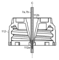
- a cone-shaped recess 112b is provided on the top surface of the lid 112 of the reagent bottle 10.
- the center line C of the recess 112b coincides with the center lines of the reagent bottle 10 and the lid 112, and is vertical when the reagent bottle 10 is placed on the reagent tray 103.
- a notch 112a is formed in the center of the lid 112 (if the positional deviation from the center line C of the notch 112a is within an acceptable range), the reagent probes 7a, 7b descending along the center line C are inserted normally into the notch 112a as shown in FIG. 4.
- the position of the notch 112a relative to the center line C may be shifted beyond the allowable range, and the notch 112a may not be formed at the bottom of the recess 112b.
- the tips of the reagent probes 7a, 7b descending along the center line C may strike the lid 112 at the bottom of the recess 112b as shown in FIG. 6, and in severe cases, the reagent probes 7a, 8a may bend.
- thin reagent probes 7a, 8a with a diameter of about 1 mm may be used in automatic analyzers, and the buckling strength of the reagent probes 7a, 8a is often insufficient.
- the piercing mechanism 200 is provided with a mechanism for making the notch 112a in the center of the lid 112 with high accuracy.
- One of the mechanisms is an alignment mechanism for the needle holder 240 (FIG. 7), and the other is a tilt mechanism for the needle 250 (FIG. 7).
- the alignment mechanism is a mechanism that allows the needle 250 to shift in the horizontal direction and is guided by the recess 112b of the lid 112 to align the needle 250 when the needle 250 is deviated from the center line C of the lid 112 when the piercing mechanism 200 is lowered to pierce the lid 112 when the reagent bottle 10 is opened.
- the tilt mechanism for the needle 250 is a mechanism that allows the needle 250 to tilt and guides the tip of the needle to the center of the lid 112 (the bottom of the recess 112b) even in a situation where the needle 250 is not sufficiently aligned.
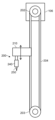
- FIG. 7 is a diagram showing a drive device for raising and lowering the piercing mechanism 200.
- the drive device for the piercing mechanism 200 shown in FIG. 7 includes a pulley 202 driven by a motor (not shown), a pulley 203 paired with the pulley 202, and a belt 204 looped around the pulleys 202 and 203.
- the pulley 202 is rotatably supported by the fixed frame 106
- the pulley 203 is rotatably supported by a support member (not shown) whose relative position with respect to the fixed frame 106 does not change.
- the piercing mechanism 200 is connected to the belt 204, and when the motor is driven in response to a command signal from the controller, the belt 204 is driven in a circulating manner between the pulleys 202 and 203, and the piercing mechanism 200 moves up and down in parallel.
- the drive/driven relationship of the pulleys 202 and 203 may be reversed.
- the lifting mechanism for the piercing mechanism 200 is not limited to a configuration using pulleys 202 and 203, and can be any suitable configuration that can lift and lower the piercing mechanism 200, such as a configuration using a ball screw or a spline shaft.
- - Alignment mechanism - Fig. 8 is a schematic diagram of the piercing mechanism 200. As shown in Fig. 8, the piercing mechanism 200 includes a frame 210, a guide 220, a guard 230, a needle holder 240, and a needle 250.
- the frame 210 is the basic structure of the piercing mechanism 200, and is formed in an L-shape with an arm portion 211 extending horizontally and a support portion 212 extending vertically.
- the arm portion 211 is fixed to the belt 204, and the support portion 212 extends downward from the arm portion 211.
- the guide 220 is a member that supports the needle 250 relative to the frame 210, and is fixed to the arm portion 211 of the frame 210.
- the guide 220 is a cylindrical member with a conical inner surface whose diameter decreases toward the bottom.
- the lower opening of the guide 220 is open, and the upper opening is covered by a pressing plate 221.
- the pressing plate 221 is fixed to the arm portion 211 with a bolt or the like.
- the guard 230 is a member that determines the allowable range of horizontal movement of the needle 250 relative to the frame 210, and is fixed to the support part 212 of the frame 210.
- This guard 230 is a cylindrical member whose center line extends vertically. The top and bottom openings of the guard 230 are open.
- Needle holder 240 is a cylindrical member through which needle 250 passes and which holds needle 250 slidably in the axial direction (up and down).
- the outer peripheral surface of tip 241 (lower end) of needle holder 240 has an outer diameter that is stepped smaller than the main body portion above, and has a conical shape with a diameter that decreases downward.
- the outer diameter of needle holder 240 is smaller than the inner diameter of guard 230, and a gap of a specified dimension is secured between the outer peripheral surface of needle holder 240 and the inner peripheral surface of guard 230. Within the range of this gap, horizontal shift of needle holder 240 and needle 250 relative to guard 230 is permitted, as mentioned above.
- the needle 250 is a member for opening the lid 112 of the reagent bottle 10, and includes a piercing needle 251 and a piercing holder 252.
- the needle 250 does not have to be divided into the piercing needle 251 and the piercing holder 400, and may be an integrally molded structure.
- the piercing needle 251 is a member that is pierced into the lid 112 to make a notch 112a ( Figure 3) in the lid 112.
- the tip of the needle 250 i.e., the lower end of the piercing needle 251, is formed sharp in order to pierce the lid 112.
- the outer diameter of the piercing needle 251 is smaller than the inner diameter of the needle holder 240, and a gap of a predetermined dimension is secured between the outer peripheral surface of the piercing needle 251 and the inner peripheral surface of the needle holder 240.
- the pierce holder 252 is a member that holds the pierce needle 251, engages with the guide 220, and slides relative to the needle holder 240.
- a protrusion 254 that protrudes radially outward from the shaft-shaped main body 253 is provided on the outer circumferential surface of the pierce holder 252, and this protrusion 254 allows the pierce holder 252, and therefore the needle 250, to slide against the inner circumferential surface of the needle holder 240.
- the pierce needle 251 is inserted and fitted into the tip surface (downward end surface) of this protrusion 254.
- the protrusion 254 is located on the tip side (lower side) of the main body 253 of the pierce holder 252.
- a coil spring 255 is housed in the cylindrical gap between the outer circumferential surface of the piercing needle 251 and the inner circumferential surface of the needle holder 240.
- the end face of the tip side (lower side) of the protrusion 254 receives the restoring force of this coil spring 255 in the extension direction, which pushes the needle 250 toward the base end side (upper side) of the needle 250, that is, in the direction in which the needle 250 retracts relative to the needle holder 240.
- a washer 256 is attached to the upper part of the inner circumferential surface of the needle holder 240 as a pressing member, and the end face of the base end side (upper side) of the protrusion 254 abuts against this washer 256, thereby defining the upper limit position of the sliding range of the needle 250 relative to the needle holder 240.
- the washer 256 may be replaced with another type of pressing member.
- the fixing member 258 that fixes the washer 256 can be, for example, a metal nut, but in this embodiment, rubber (rubber plug) is used to make it easier to remove and attach when cleaning in preparation for the generation of wear powder.
- the main body 253 of the pierce holder 252 protrudes upward from the needle holder 240.
- a base (upper end) 257 with a larger diameter than the main body 253 is provided on the upper side of the main body 253.
- the base of the pierce holder 252 i.e., the base of the needle 250
- the large diameter base 257 of the needle 250 gets caught on the inner surface of the guide 220, which narrows downward, and the needle 250 hangs from the guide 220 without falling out of the guide 220.
- the outer surface of the base 257 is also tapered according to the inner surface of the guide 220, but this is not limited to this.
- the diameter of the lower opening of the guide 220 is smaller than the diameter of the base 257 of the needle 250 and smaller than the outer diameter of the needle holder 240. Therefore, during maintenance, the pressing plate 221 can be removed and the needle 250 can be pulled out upward together with the needle holder 240 via the guide 220.
- the piercing mechanism 200 configured as described above is lowered by the belt 204, and the tip 241 of the needle holder 240 enters the recess 112b of the lid 112 of the reagent bottle 10, and the needle holder 240 comes into contact with the lid 112.
- the piercing mechanism 200 further descends, and the base 257 of the needle 250, which comes to rest together with the needle holder 240 that has come into contact with the lid 112, is pushed downward by the pressure plate 221. This causes the needle 250 to be pushed downward from the needle holder 240 against the restoring force of the coil spring 255, and the needle 250 is pierced into the lid 112, penetrating the lid 112 and opening the reagent bottle 10.
- the piercing mechanism 200 places the needle holder 240 against the reagent bottle 10 that is inserted into the automated analyzer and transported to the reagent storage 9, protrudes the needle 250 from the needle holder 240, and pierces the needle 250 to form a cut 112a in the lid 112 of the reagent bottle 10, thereby opening the reagent bottle 10.
- the center line O of the needle holder 240 coincides with or approaches the center line C of the lid 112, and a notch 112a is formed at the center position of the lid 112 or at a position within the allowable error range from the center.
- the mechanism that allows this shifting of the needle holder 240 and the needle 250 is the centering mechanism of the needle holder 240.
- the piercing mechanism 200 rises and the needle 250 is pulled out of the lid 112. Even if the alignment mechanism functions and the needle 250 shifts when the reagent bottle 10 is opened, the needle 250 leaves the lid 112 and the base 257 is guided by the guide 220. As a result, the needle holder 240 automatically returns to a position where the center line O coincides with the center of the guide 220.
- FIG. 9 is a cross-sectional view including the central axis of the assembly of the needle holder 240 and the needle 250
- FIG. 10 is a perspective cross-sectional view of the main parts of the assembly of the needle holder 240 and the needle 250
- FIG. 11 is an enlarged view of part A in FIG.
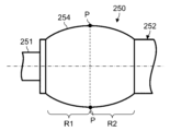
- the protrusion 254 of the needle 250 is shaped to make point contact with the inner surface of the needle holder 240 at contact point P when the center line is aligned with the needle holder 240, as viewed in a cross section cut along a plane passing through the center line O of the needle holder 240. Therefore, the needle 250 is freely tiltable relative to the needle holder 240 within the range of the gap between the needle 250 and the inner surface of the needle holder 240. In this way, the mechanism that allows the needle 250 to tilt relative to the needle holder 240 is the tilt mechanism.
- the cross section of the protrusion 254 (cross section perpendicular to the center line O) is circular, and the inner surface of the needle holder 240 and the protrusion 254 of the needle 250 make point contact at a tangent point P when viewed in cross section ( Figure 9), but the tangent point P continues 360 degrees around the circumference of the needle 250 and makes line contact at a ring-shaped tangent line L when viewed three-dimensionally.
- the protrusion 254 of the needle 250 is configured so as not to make surface contact with the inner surface of the needle holder 240 even when the needle 250 is inclined relative to the needle holder 240.
- the plane including the ring-shaped tangent line L is perpendicular to the center line of the needle 250.
- the outer peripheral surface of the protrusion 254 is formed as a sphere whose diameter corresponds to the inner peripheral surface of the needle holder 240, which is its sliding counterpart, or a curved surface with a radius of curvature close to that, and the needle 250 can be tilted relative to the needle holder 240 while maintaining to some extent a state in which the protrusion 254 is in contact with the inner peripheral surface of the needle holder 240.
- the protrusion 254 has a predetermined length in the axial direction, and as shown in FIG. 11, includes a first region R1 on the tip side (lower side) of the needle 250 and a second region R2 on the base side (upper side) of the needle 250, sandwiching the contact point P (tangent line L).
- the outer circumferential surface of the protrusion 254 (both the first region R1 and the second region R2) is a curved surface with a radius of curvature of a sphere or a radius of curvature close to that of a sphere, and in both the first region R1 and the second region R2, the gap between the outer circumferential surface of the protrusion 254 and the inner circumferential surface of the needle holder 240 increases monotonically as it moves away from the contact point P in the axial direction.
- the radius of curvature of the outer circumferential surface of the first region R1 and the second region R2 is the same, but may be different.
- the radius of curvature of the outer circumferential surface of the protrusion 254 can be, for example, 7 or 8 mm.
- the length of the first region R1 in the axial direction of the needle 250 is shorter than the length of the second region R2. Therefore, the maximum distance (maximum gap) d2 between the outer peripheral surface of the second region R2 and the inner peripheral surface of the needle holder 240 is larger than the maximum distance (maximum gap) d1 between the outer peripheral surface of the first region R1 and the inner peripheral surface of the needle holder 240.
- the maximum distance d1 between the first region R1 and the inner peripheral surface of the needle holder 240 (i.e., the gap between the outer edge of the tip surface of the protrusion 254 and the inner peripheral surface of the needle holder 240) is smaller than the wire diameter d3 of the coil spring 255 (the diameter of the wire of the coil spring 255).
- Figures 12 and 13 are explanatory diagrams of how the tilt mechanism functions.
- the centering mechanism will function and the needle 250 will shift together with the needle holder 240, causing the notch 112a to be made in the center of the lid 112.
- the trajectory of the tip 241 of the needle holder 240 may deviate from the center of the upper opening of the recess 112b of the lid 112 (the entire tip 241 may not fit into the upper opening of the recess 112b in a plan view) as shown by the dotted arrow in Figure 12.
- the tip 241 may approach the edge of the recess 112b of the lid 112 as shown in Figure 13, and the tip 241 may get caught on the upper surface of the lid 112 (the upward surface excluding the recess 112b), causing the centering mechanism of the needle holder 240 to not function.
- the tip 241 may get caught on the upper surface of the lid 112 (the upward surface excluding the recess 112b), causing the centering mechanism of the needle holder 240 to not function.
- the notch 112a may be formed at a position that is displaced beyond the allowable range from the center of the lid 112 (for example, on the slope of the recess 112b).
- the needle 250 can be tilted freely with respect to the needle holder 240 by the tilt mechanism. Therefore, even if the centers of the needle holder 240 and the lid 112 do not coincide as shown in FIG. 13, as long as the trajectory of the tip of the needle 250 does not deviate from the recess 112b of the lid 112, the tip of the needle 250 is guided by the inclined surface of the recess 112b as the needle 250 is pushed out of the needle holder 240, and the needle 250 tilts at an angle ⁇ corresponding to the deviation of the center lines C and O with respect to the needle holder 240 within the movable range allowed by the tilt mechanism. Therefore, as shown in FIG. 13, the tip of the needle 250 is guided to the bottom of the recess 112b of the lid 112, and the notch 112a is formed at the center position of the lid 112 or at a position within the allowable error from the center.
- the shape of the protrusion 254 may be any shape that avoids surface contact with the inner circumferential surface of the needle holder 240.
- FIG. 14 is a schematic diagram showing the main parts of the first deformation of the needle 250.
- FIG. 9 shows an example in which the first region R1 of the protrusion 254 is shorter than the second region R2.
- the axial lengths of the first region R1 and the second region R2 may be equal as shown in FIG. 14, or the second region R2 may be shorter than the first region R1.
- FIG. 15 is a schematic diagram showing the main parts of the second deformation of the needle 250.
- FIG. 9 shows an example in which the outer peripheral surface of the protrusion 254 is curved.
- the outer peripheral surface of the protrusion 254 (at least one of the first region R1 and the second region R2) may be a tapered surface (the protrusion 254 is conical) as shown in FIG. 15.
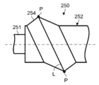
- Figure 16 is a schematic diagram showing the main parts of the third deformation of the needle 250.
- Figure 9 illustrates a configuration in which a surface including a ring-shaped tangent L, which is a collection of contact points P between the inner surface of the needle holder 240 and the needle 250, is perpendicular to the center line of the needle 250.
- the surface including the ring-shaped tangent L may be inclined with respect to the center line of the needle 250 (the dashed line in Figure 16).
- Fig. 17 is a schematic diagram showing the main parts of the fourth variation of the needle 250.
- the outer peripheral surface of the protrusion 254 is formed as a curved surface, as in the example of Fig. 14, but as shown in Fig. 17, the outer peripheral surface of the protrusion 254, in which the surface including the tangent line L is inclined, may be a tapered surface, as in the example of Fig. 15.
- FIG. 18 is a schematic diagram showing the main parts of the fifth modification of the needle 250.
- the contact points P between the protrusion 254 and the needle holder 240 are continuous for 360 degrees and form the tangent line L.
- multiple protrusions 254 may be provided in the circumferential direction of the needle 250, and each protrusion 254 may contact the inner surface of the needle holder 240 at a single contact point P.
- each protrusion 254 is independent, but adjacent protrusions 254 may be connected to each other. In this way, the needle 250 may be in point contact with the inner surface of the needle holder 240 at multiple contact points P that exist intermittently in the circumferential direction.
- the alignment mechanism and tilt mechanism function passively in accordance with the operation of the piercing mechanism 200, with the needle holder 240 or the needle 250 being guided in the recess 112b of the reagent bottle 10, without the need to control the reagent autoloader mechanism 100 with a controller, for example. Therefore, there is no need to add a position sensor or the like and prepare a new program for alignment of the needle holder 240 or tilt of the needle 250.
- an existing automatic analyzer employing the conventional configuration illustrated in Fig.
- the needle N or the piercing holder can be replaced with the needle 250 or the piercing holder 252 according to this embodiment (and if necessary, the parts that engage with the needle N can also be replaced), to construct the automatic analyzer according to this embodiment.
- an automatic analyzer according to this embodiment can be constructed from an existing automatic analyzer, and problems with opening the reagent bottle 10 can be prevented.
- the needle holder 240 is placed against the reagent bottle 10, and the needle protrudes from the needle holder 240 to form the notch 112a in the reagent bottle 10.
- the needle 250 is in contact with the inner peripheral surface of the needle holder 240 at a point or a line, so that when the needle 250 protrudes from the needle holder 240, the needle 250 is allowed to incline relative to the needle holder 240.
- the tip 241 of the needle holder 240 deviates from the center of the recess 112b of the lid 112 and approaches the upper surface edge of the lid 112, the needle 250 that subsequently protrudes from the needle holder 240 will incline relative to the needle holder 240 in accordance with the slope of the recess 112b.
- the tip of the needle 250 is guided to the bottom of the recess 112 b , and a notch 112 a can be formed in the center of the lid 112 .
- the notch 112a can be formed in the desired position range of the lid 112 of the reagent bottle 10, specifically, at a position within the allowable error from the center. Furthermore, by improving the positional accuracy of the notch 112a of the reagent bottle 10, the reagent probes 7a and 8a can repeatedly dispense the reagent quickly and accurately, which contributes to improving the processing capacity of the automatic analyzer.
- the needle N is in surface contact with the needle holder H, for example as in the configuration illustrated in FIG. 19, when the needle holder H comes into contact with the reagent bottle 10 and the needle N is pushed out of the needle holder H, the frictional resistance of the needle N against the needle holder H is large in proportion to the contact area. In this case, the sliding resistance of the needle N is large, and the needle holder H and the needle N are also easily worn out accordingly.
- the needle 250 contacts the needle holder 240 at a line or point, which reduces the sliding resistance of the needle 250 and makes operation smoother, while also reducing wear between the needle holder 240 and the needle 250.
- the protrusion 254 has a first region R1 on the tip side of the needle 250 and a second region R2 on the base side, sandwiching the contact point P, and both the first region R1 and the second region R2 are formed so that the gap between them and the inner surface of the needle holder 240 increases monotonically as they move away from the contact point P. Therefore, when the needle 250 is tilted relative to the needle holder 240, it is possible to prevent parts of the protrusion 254 other than the contact point P from touching the inner surface of the needle holder 240 and hindering the tilting of the needle 250.
- the gap between the tip (lower end) of the first region R1 and the inner surface of the needle holder 240 is smaller than the gap between the base end (upper end) of the second region R2 and the inner surface of the needle holder 240.
- the gap between the base end (upper end) of the second region R2 and the inner surface of the needle holder 240 can be secured to be larger than the gap between the tip (lower end) of the first region R1 and the inner surface of the needle holder 240. Therefore, the needle 250 (for example, the main body 253 of the needle 250) can be made thinner on the second region R2 side than the contact point P, which has the advantages of reducing the weight of the needle 250 and increasing the tiltable angle of the needle 250.
- the maximum distance d1 between the inner circumferential surface of the needle holder 240 and the first region R1 is set to be smaller than the wire diameter d3 of the coil spring 255. This prevents the coil spring 255 from getting caught between the inner circumferential surface of the needle holder 240 and the first region R1 when the needle 250 is tilted, and prevents a decrease in the smoothness of the operation of the needle 250.
- the angle of the needle 250 that ultimately pierces the lid 112 can be made closer to vertical while the piercing mechanism 200 descends diagonally relative to the reagent bottle 10.
- the piercing holder 252 having the protrusion 254 can be used repeatedly across replacement of the piercing needle 251. Conversely, if wear of the protrusion 254 progresses, it is conceivable that it may become necessary to replace the piercing holder 252 even if there is no need to replace the piercing needle 251. In such a case, it is possible to avoid unnecessary replacement of the piercing needle 251 due to wear of the protrusion 254.
- the automated analyzer is equipped with a piercing mechanism 200 that automatically opens the reagent bottles 10 that contain the reagent bottles 10, a reagent transport mechanism 101 that transports the reagent bottles 10 to the reagent storage 9, and the like, so the operator does not need to open the reagent bottles 10 themselves and store them directly in the reagent storage 9. Because the process of opening the reagent bottles 10 and transporting them to the reagent storage 9 is performed automatically, the burden on the operator can be reduced.
- the protrusion 254 may be attached to the piercing holder 252 later.
- the protrusion 254 may be manufactured as a separate ring-shaped member and fitted into the piercing holder 252.
- the tip of the pierce needle 251 protrudes from the needle holder 240 even when the protrusion 254 hits the washer 256, and the tip of the pierce needle 251 is always exposed from the needle holder 240 ( Figure 9).
- the pierce needle 251 is extended from the needle holder 240 and penetrates the lid 112 when the needle holder 240 is in contact with the reagent bottle 10. If this function can be ensured, the tip of the pierce needle 251 may be configured to fit inside the needle holder 240 when the coil spring 255 is fully extended.
- the piercing mechanism 200 may also be configured to include multiple needles 250, and to simultaneously make cuts 112a in multiple lids 112 of a reagent bottle 10 having multiple lids 112.
Landscapes
- Physics & Mathematics (AREA)
- Health & Medical Sciences (AREA)
- Life Sciences & Earth Sciences (AREA)
- Chemical & Material Sciences (AREA)
- Analytical Chemistry (AREA)
- Biochemistry (AREA)
- General Health & Medical Sciences (AREA)
- General Physics & Mathematics (AREA)
- Immunology (AREA)
- Pathology (AREA)
- Automatic Analysis And Handling Materials Therefor (AREA)
Priority Applications (3)
| Application Number | Priority Date | Filing Date | Title |
|---|---|---|---|
| CN202380093221.5A CN120641761A (zh) | 2023-03-23 | 2023-12-18 | 穿孔机构及具有该穿孔机构的自动分析装置 |
| EP23928796.4A EP4685493A1 (en) | 2023-03-23 | 2023-12-18 | Piercing mechanism and automatic analysis device including same |
| JP2025508136A JPWO2024195230A1 (https=) | 2023-03-23 | 2023-12-18 |
Applications Claiming Priority (2)
| Application Number | Priority Date | Filing Date | Title |
|---|---|---|---|
| JP2023046882 | 2023-03-23 | ||
| JP2023-046882 | 2023-03-23 |
Publications (1)
| Publication Number | Publication Date |
|---|---|
| WO2024195230A1 true WO2024195230A1 (ja) | 2024-09-26 |
Family
ID=92841694
Family Applications (1)
| Application Number | Title | Priority Date | Filing Date |
|---|---|---|---|
| PCT/JP2023/045333 Ceased WO2024195230A1 (ja) | 2023-03-23 | 2023-12-18 | ピアス機構及びこれを備えた自動分析装置 |
Country Status (4)
| Country | Link |
|---|---|
| EP (1) | EP4685493A1 (https=) |
| JP (1) | JPWO2024195230A1 (https=) |
| CN (1) | CN120641761A (https=) |
| WO (1) | WO2024195230A1 (https=) |
Citations (4)
| Publication number | Priority date | Publication date | Assignee | Title |
|---|---|---|---|---|
| JPS5231599U (https=) * | 1975-08-27 | 1977-03-05 | ||
| JPH0618531A (ja) * | 1992-04-09 | 1994-01-25 | F Hoffmann La Roche Ag | 試薬キットと自動分析装置 |
| JP2004125677A (ja) * | 2002-10-04 | 2004-04-22 | Hitachi High-Technologies Corp | 自動分析装置 |
| WO2017141696A1 (ja) | 2016-02-19 | 2017-08-24 | 株式会社日立ハイテクノロジーズ | 自動分析装置 |
-
2023
- 2023-12-18 JP JP2025508136A patent/JPWO2024195230A1/ja active Pending
- 2023-12-18 EP EP23928796.4A patent/EP4685493A1/en active Pending
- 2023-12-18 WO PCT/JP2023/045333 patent/WO2024195230A1/ja not_active Ceased
- 2023-12-18 CN CN202380093221.5A patent/CN120641761A/zh active Pending
Patent Citations (4)
| Publication number | Priority date | Publication date | Assignee | Title |
|---|---|---|---|---|
| JPS5231599U (https=) * | 1975-08-27 | 1977-03-05 | ||
| JPH0618531A (ja) * | 1992-04-09 | 1994-01-25 | F Hoffmann La Roche Ag | 試薬キットと自動分析装置 |
| JP2004125677A (ja) * | 2002-10-04 | 2004-04-22 | Hitachi High-Technologies Corp | 自動分析装置 |
| WO2017141696A1 (ja) | 2016-02-19 | 2017-08-24 | 株式会社日立ハイテクノロジーズ | 自動分析装置 |
Also Published As
| Publication number | Publication date |
|---|---|
| EP4685493A1 (en) | 2026-01-28 |
| JPWO2024195230A1 (https=) | 2024-09-26 |
| CN120641761A (zh) | 2025-09-12 |
Similar Documents
| Publication | Publication Date | Title |
|---|---|---|
| JP4980671B2 (ja) | 血液試料分析装置 | |
| US9823109B2 (en) | Chemical analyzer | |
| JP4485137B2 (ja) | 臨床分析機の校正方法および臨床分析機のディスペンサーの自動整合方法 | |
| EP1542020B1 (en) | Analyzer having removable holders and a centrifuge | |
| CN108603894B (zh) | 自动分析装置 | |
| EP2703819A1 (en) | Sample processing apparatus and sample processing method | |
| JP7496439B2 (ja) | 自動分析装置、位置調整用治具及び位置調整方法 | |
| US8507280B2 (en) | Method of normalizing surface tension of a sample fluid | |
| JP7514185B2 (ja) | 自動分析方法および装置並びに検体ラック | |
| JP5336555B2 (ja) | 検体分析装置 | |
| WO2024195230A1 (ja) | ピアス機構及びこれを備えた自動分析装置 | |
| CN116034277A (zh) | 自动分析装置 | |
| JP2022133528A (ja) | 自動分析装置 | |
| JP7773353B2 (ja) | 自動分析装置 | |
| JP7490893B2 (ja) | 自動分析装置 | |
| JP6808574B2 (ja) | 容器収容ユニット及び自動分析装置 | |
| JP6815801B2 (ja) | 自動分析装置 | |
| JP7410321B2 (ja) | 自動分析装置 | |
| JPH0729465U (ja) | 生化学自動分析装置 | |
| JP5330122B2 (ja) | 自動分析装置 | |
| CN113295876A (zh) | 自动分析装置 | |
| WO2016017294A1 (ja) | 自動分析装置 | |
| JPH08101216A (ja) | 自動分析装置 | |
| JP2026029908A (ja) | 自動分析装置、及び、分注装置 | |
| WO2023145194A1 (ja) | 自動分析装置 |
Legal Events
| Date | Code | Title | Description |
|---|---|---|---|
| 121 | Ep: the epo has been informed by wipo that ep was designated in this application |
Ref document number: 23928796 Country of ref document: EP Kind code of ref document: A1 |
|
| ENP | Entry into the national phase |
Ref document number: 2025508136 Country of ref document: JP Kind code of ref document: A |
|
| WWE | Wipo information: entry into national phase |
Ref document number: 2025508136 Country of ref document: JP |
|
| WWE | Wipo information: entry into national phase |
Ref document number: 202380093221.5 Country of ref document: CN |
|
| WWP | Wipo information: published in national office |
Ref document number: 202380093221.5 Country of ref document: CN |
|
| WWE | Wipo information: entry into national phase |
Ref document number: 2023928796 Country of ref document: EP |
|
| NENP | Non-entry into the national phase |
Ref country code: DE |
|
| ENP | Entry into the national phase |
Ref document number: 2023928796 Country of ref document: EP Effective date: 20251023 |
|
| ENP | Entry into the national phase |
Ref document number: 2023928796 Country of ref document: EP Effective date: 20251023 |
|
| ENP | Entry into the national phase |
Ref document number: 2023928796 Country of ref document: EP Effective date: 20251023 |
|
| ENP | Entry into the national phase |
Ref document number: 2023928796 Country of ref document: EP Effective date: 20251023 |
|
| ENP | Entry into the national phase |
Ref document number: 2023928796 Country of ref document: EP Effective date: 20251023 |
|
| ENP | Entry into the national phase |
Ref document number: 2023928796 Country of ref document: EP Effective date: 20251023 |