WO2024190890A1 - 鋼構造物の補修方法及び鋼構造物の補修用接着シート - Google Patents
鋼構造物の補修方法及び鋼構造物の補修用接着シート Download PDFInfo
- Publication number
- WO2024190890A1 WO2024190890A1 PCT/JP2024/010132 JP2024010132W WO2024190890A1 WO 2024190890 A1 WO2024190890 A1 WO 2024190890A1 JP 2024010132 W JP2024010132 W JP 2024010132W WO 2024190890 A1 WO2024190890 A1 WO 2024190890A1
- Authority
- WO
- WIPO (PCT)
- Prior art keywords
- rust
- steel structure
- adhesive sheet
- repairing
- layer
- Prior art date
- Legal status (The legal status is an assumption and is not a legal conclusion. Google has not performed a legal analysis and makes no representation as to the accuracy of the status listed.)
- Ceased
Links
Classifications
-
- B—PERFORMING OPERATIONS; TRANSPORTING
- B05—SPRAYING OR ATOMISING IN GENERAL; APPLYING FLUENT MATERIALS TO SURFACES, IN GENERAL
- B05D—PROCESSES FOR APPLYING FLUENT MATERIALS TO SURFACES, IN GENERAL
- B05D3/00—Pretreatment of surfaces to which liquids or other fluent materials are to be applied; After-treatment of applied coatings, e.g. intermediate treating of an applied coating preparatory to subsequent applications of liquids or other fluent materials
- B05D3/12—Pretreatment of surfaces to which liquids or other fluent materials are to be applied; After-treatment of applied coatings, e.g. intermediate treating of an applied coating preparatory to subsequent applications of liquids or other fluent materials by mechanical means
-
- B—PERFORMING OPERATIONS; TRANSPORTING
- B05—SPRAYING OR ATOMISING IN GENERAL; APPLYING FLUENT MATERIALS TO SURFACES, IN GENERAL
- B05D—PROCESSES FOR APPLYING FLUENT MATERIALS TO SURFACES, IN GENERAL
- B05D7/00—Processes, other than flocking, specially adapted for applying liquids or other fluent materials to particular surfaces or for applying particular liquids or other fluent materials
- B05D7/14—Processes, other than flocking, specially adapted for applying liquids or other fluent materials to particular surfaces or for applying particular liquids or other fluent materials to metal, e.g. car bodies
-
- E—FIXED CONSTRUCTIONS
- E01—CONSTRUCTION OF ROADS, RAILWAYS, OR BRIDGES
- E01D—CONSTRUCTION OF BRIDGES, ELEVATED ROADWAYS OR VIADUCTS; ASSEMBLY OF BRIDGES
- E01D1/00—Bridges in general
-
- E—FIXED CONSTRUCTIONS
- E01—CONSTRUCTION OF ROADS, RAILWAYS, OR BRIDGES
- E01D—CONSTRUCTION OF BRIDGES, ELEVATED ROADWAYS OR VIADUCTS; ASSEMBLY OF BRIDGES
- E01D22/00—Methods or apparatus for repairing or strengthening existing bridges ; Methods or apparatus for dismantling bridges
-
- E—FIXED CONSTRUCTIONS
- E04—BUILDING
- E04G—SCAFFOLDING; FORMS; SHUTTERING; BUILDING IMPLEMENTS OR AIDS, OR THEIR USE; HANDLING BUILDING MATERIALS ON THE SITE; REPAIRING, BREAKING-UP OR OTHER WORK ON EXISTING BUILDINGS
- E04G23/00—Working measures on existing buildings
- E04G23/02—Repairing, e.g. filling cracks; Restoring; Altering; Enlarging
Definitions
- This disclosure relates to a method for repairing steel structures and an adhesive sheet for repairing steel structures.
- Steel structures such as bridges are primarily made of steel. As steel deteriorates, the steel structure must be repaired. Various repair methods have been considered (see, for example, the background art of Patent Document 1).
- a known method for repairing a steel structure with deteriorated parts is to carry out surface preparation such as blasting on the deteriorated parts of the steel structure, then apply a corrosion-resistant base coat, coat the deteriorated parts with epoxy resin paint or the like that has excellent blocking properties against corrosion factors (water or oxygen), and then coat the deteriorated parts with fluororesin paint or the like that has excellent weather resistance.
- the purpose of this disclosure is to provide a method that enables repair of steel structures with deteriorated areas in a short period of time.
- the steel structure repair method disclosed herein is a method for repairing a steel structure having a deteriorated portion, and includes a first step of preparing a support and an adhesive sheet having an adhesive layer provided on one surface of the support, a second step of performing base preparation on the deteriorated portion of the steel structure to form a base preparation surface that may have an active film, a third step of performing a rust prevention treatment on the base preparation surface of the steel structure to form a rust prevention treated surface, and a fourth step of placing an adhesive sheet on the rust prevention treated surface of the steel structure.
- This disclosure provides a method that allows for the repair of steel structures with deteriorated areas in a short period of time.
- FIG. 1 is a schematic cross-sectional view showing steps of a method for repairing a steel structure.
- FIG. 2A is a diagram showing a method for measuring the storage modulus of an adhesive layer.
- FIG. 2B is a schematic cross-sectional view showing a laminate provided in the adhesive sheet.
- FIG. 3 is a schematic cross-sectional view showing a support provided in the adhesive sheet.
- FIG. 4 is a schematic cross-sectional view showing a method of weather resistance testing.
- FIG. 5 is a schematic cross-sectional view showing a method of weather resistance testing.
- the numerical range of the parameter may be constructed by combining any one of the upper limit candidates and any one of the lower limit candidates.
- the numerical range of parameter B may be A1 or more and A4 or less, A1 or more and A5 or less, A1 or more and A6 or less, A2 or more and A4 or less, A2 or more and A5 or less, A2 or more and A6 or less, A3 or more and A4 or less, A3 or more and A5 or less, or A3 or more and A6 or less.
- the method for repairing a steel structure disclosed herein comprises: A method for repairing a steel structure having a deteriorated portion, comprising: a first step of preparing an adhesive sheet having a support and an adhesive layer provided on one surface of the support; A second step of performing a surface preparation on the deteriorated portion of the steel structure to form a surface preparation surface which may have an active film; A third step of performing a rust-proofing treatment on the surface of the steel structure to form a rust-proofed surface; and a fourth step of placing an adhesive sheet on the rust-proofed surface of the steel structure.
- the steel structure repair method of the present disclosure further includes a step 3a of forming a coating resin layer on the rust-proofed surface (e.g., the rust-proof coating film) of the steel structure.
- the steel structure repair method of the present disclosure further includes a fifth step of forming a topcoat coating film on the surface of the adhesive sheet placed on the rust-proofed surface of the steel structure.
- an adhesive sheet is prepared.
- a steel structure having a deteriorated portion may be prepared.
- the steel structure to be repaired is a structure having a steel material as a base material.
- Examples of the steel structure include bridges, bridge piers, steel towers, steel pipes, chimneys, tanks, plants, pipelines, rolled plates, and roofs.
- Examples of the steel material include alloy steels such as nickel-chromium steel, nickel-chromium-molybdenum steel, chromium steel, chromium-molybdenum steel, and manganese steel, as well as carbon steel.
- the steel structure may be, for example, an architectural structure or a civil engineering structure.
- the steel structure to be repaired has areas on its surface where rust, such as red rust (e.g., iron oxide (Fe2O3)), has developed due to corrosion factors such as water and oxygen.
- a coating (hereinafter also referred to as the "pre-repair coating” or “old coating”) is formed by painting an anti-rust paint or anti-corrosion paint on the steel material to prevent rusting.
- Such coatings may crack or swell in parts due to deterioration over time or construction or repairs performed on the steel structure.
- deteriorated parts of the steel structure shown in this specification, such rusted areas or areas where cracks and swelling have developed in the coating are referred to as deteriorated parts of the steel structure.
- Figure 1A shows a schematic cross-sectional view of a deteriorated part of a steel structure.
- a pre-repair coating (old coating) 20 is provided on steel material 10, and rust 30 has developed.
- the steel structure to be repaired has a deteriorated portion.
- a surface preparation is performed on the deteriorated portion, a surface preparation surface which may have an active film is formed, an anti-rust treatment is performed on the surface preparation, an anti-rust treated surface is formed, and an adhesive sheet is placed on the anti-rust treated surface.
- This type of repair method allows repair treatment of the steel structure to be performed in a short period of time and at low cost, compared to, for example, heavy-duty corrosion protection painting.
- the adhesive sheet comprises a support and an adhesive layer provided on one surface of the support.
- the support is preferably, for example, a resin film.
- resin materials constituting the resin film include polyolefins such as polyethylene and polypropylene, polyvinyl chloride, vinylidene chloride-vinyl chloride copolymers, polyesters such as polyethylene terephthalate, polycarbonates, polyarylates, styrene resins, acrylic resins, acrylic urethane resins, urethane resins, fluororesins, acetyl cellulose, polyamides, and polyimides.
- the support may be a single layer or multiple layers, for example a laminated film of resin films.
- the support may contain additives.
- additives include pigments, dyes, colorants, antistatic agents, flame retardants, mildew inhibitors, ultraviolet absorbers, antioxidants, light stabilizers, plasticizers, leveling agents, flow regulators, defoamers, and dispersants.
- the support has excellent weather resistance.
- the support may contain weather resistance agents such as ultraviolet absorbers, antioxidants, and light stabilizers. This allows, for example, the topcoat coating film described below to be made thinner, and also makes it possible to omit the formation of the topcoat coating film.
- the thickness of the support is preferably 10 ⁇ m or more, more preferably 20 ⁇ m or more, even more preferably 30 ⁇ m or more, even more preferably 50 ⁇ m or more, particularly preferably 100 ⁇ m or more, and is preferably 5000 ⁇ m or less, more preferably 4000 ⁇ m or less, even more preferably 3000 ⁇ m or less, even more preferably 2000 ⁇ m or less, particularly preferably 1000 ⁇ m or less, taking into consideration the finish after repair of the steel structure, i.e., the finish after the adhesive sheet is applied to the steel structure, and the ease of handling and application of the adhesive sheet.
- the support may include a fiber-reinforced resin layer.
- An adhesive sheet including such a support has, for example, excellent impact resistance.
- the fiber-reinforced resin layer is, for example, a layer containing a resin material and reinforcing fibers.
- the resin material include the resin materials described above.
- the reinforcing fibers may be inorganic fibers or organic fibers. Examples of the inorganic fibers include glass fibers, carbon fibers, silicon-titanium-carbon fibers, boron fibers, and metal fibers. Examples of the organic fibers include aramid fibers, vinylon fibers, polyester fibers, and polyamide fibers.
- the reinforcing fibers may be in a mesh (network) shape.
- the fiber-reinforced resin layer may contain a glass mesh as a reinforcing fiber.
- the thickness of the fiber-reinforced resin layer is preferably 50 ⁇ m or more, more preferably 75 ⁇ m or more, even more preferably 100 ⁇ m or more, even more preferably 125 ⁇ m or more, particularly preferably 150 ⁇ m or more, and is preferably 550 ⁇ m or less, more preferably 525 ⁇ m or less, even more preferably 500 ⁇ m or less, even more preferably 475 ⁇ m or less, particularly preferably 450 ⁇ m or less.
- An adhesive sheet having a fiber-reinforced resin layer of such a thickness has, for example, excellent impact resistance.
- the support may, for example, comprise a laminate having a fiber-reinforced resin layer and a resin layer in this order in the thickness direction, or a laminate having a first resin layer, a fiber-reinforced resin layer, and a second resin layer in this order in the thickness direction.
- resin materials constituting the resin layer, the first resin layer, and the second resin layer include the resin materials described above.
- the support may, for example, comprise a laminate having a fiber-reinforced resin layer including polyethylene and a glass mesh and a polyethylene layer in this order, or a laminate having a first polyethylene layer, a fiber-reinforced resin layer including polyethylene and a glass mesh, and a second polyethylene layer in this order.
- the thickness of the resin layer, the first resin layer, and the second resin layer is each independently preferably 10 ⁇ m or more, more preferably 20 ⁇ m or more, even more preferably 30 ⁇ m or more, even more preferably 50 ⁇ m or more, particularly preferably 100 ⁇ m or more, and preferably 1000 ⁇ m or less, more preferably 800 ⁇ m or less, even more preferably 600 ⁇ m or less, even more preferably 500 ⁇ m or less, particularly preferably 400 ⁇ m or less.
- the support may include a gas barrier layer such as a vapor deposition film.
- a gas barrier layer such as a vapor deposition film.
- Such a support includes, for example, a gas barrier film, particularly a vapor deposition film, which includes a resin film and a gas barrier layer such as a vapor deposition film provided on the resin film.
- An adhesive sheet including such a support has excellent gas barrier properties, particularly oxygen barrier properties and water vapor barrier properties, and can suppress, for example, rusting of a steel structure and deterioration of a coating film after repair.
- the resin film in the gas barrier film may be any of the above-mentioned resin films.
- the thickness of the resin film is preferably 5 ⁇ m or more, more preferably 10 ⁇ m or more, and is preferably 100 ⁇ m or less, more preferably 50 ⁇ m or less.
- Examples of the deposition film include deposition films containing one or more metals, deposition films containing one or more inorganic oxides, and deposition films containing one or more metals and one or more inorganic oxides.
- metals include aluminum, chromium, tin, nickel, copper, silver, gold, and platinum.
- inorganic oxides include aluminum oxide, silicon oxide, magnesium oxide, calcium oxide, zirconium oxide, titanium oxide, boron oxide, hafnium oxide, barium oxide, and silicon carbide oxide (carbon-containing silicon oxide).
- aluminum deposition film, aluminum oxide (alumina) deposition film, and silicon oxide (silica) deposition film are preferred.
- the thickness of the deposition film is preferably 1 nm or more, more preferably 5 nm or more, and even more preferably 10 nm or more, and is preferably 150 nm or less, more preferably 100 nm or less, and even more preferably 80 nm or less.
- methods for forming a vapor-deposited film include physical vapor deposition methods (PVD methods) such as vacuum deposition, sputtering, and ion plating, and chemical vapor deposition methods (CVD methods) such as plasma chemical vapor deposition, thermal chemical vapor deposition, and photochemical vapor deposition.
- PVD methods physical vapor deposition methods
- CVD methods chemical vapor deposition methods
- vapor-deposited films include vapor-deposited polyester films, such as vapor-deposited polyethylene terephthalate films, and vapor-deposited polyamide films.
- the oxygen transmission rate (OTR, unit: cc/(m2 ⁇ day ⁇ atm)) of an adhesive sheet having a gas barrier layer is preferably 3.0 or less, more preferably 2.5 or less, and even more preferably 2.0 or less.
- the lower limit of the OTR is preferably as low as possible, but may be, for example, 0.01, 0.05, or 0.1.
- the OTR is measured in accordance with JIS K7126-2:2006 at a temperature of 23°C and a humidity of 60% RH.
- the oxygen transmission rate can be measured using an oxygen transmission rate measuring device (OX-TRAN2/20, manufactured by MOCON).
- the water vapor transmission rate (WVTR, unit: g/(m2 ⁇ day)) of an adhesive sheet having a gas barrier layer is preferably 3.0 or less, more preferably 2.5 or less, and even more preferably 2.0 or less.
- the lower limit of WVTR is preferably as low as possible, but may be, for example, 0.01, 0.05, or 0.1.
- WVTR is measured in accordance with JIS K7129-2:2019 at a temperature of 40°C and a humidity of 90% RH. WVTR can be measured using a water vapor transmission rate measuring device (PERMATRAN-w 3/33, manufactured by MOCON).
- the layer constituting the surface of the support opposite to the surface facing the adhesive layer is preferably a resin layer such as polyolefin, acrylic resin, acrylic urethane resin, or urethane resin, from the viewpoint of adhesion to the topcoat coating film described below.
- the support may have a surface resin layer as a surface layer opposite to the surface layer facing the adhesive layer. This, for example, improves the weather resistance of the repaired steel structure, and ensures rust prevention even long after construction.
- a colored surface resin layer may also be formed. In this case, the fifth step described below may be omitted.
- Examples of the resin material constituting the surface resin layer include fluororesin, urethane resin, acrylic resin, butadiene resin, silicone resin, vinyl ester resin, and epoxy resin. Among these, fluororesin is preferred. Examples of fluororesin include polyvinyl fluoride, polytetrafluoroethylene, perfluoroalkoxyalkane, and ethylene-tetrafluoroethylene copolymer.
- the surface resin layer may contain additives such as pigments, dyes, dispersants, defoamers, thickeners, leveling agents, anti-settling agents, anti-sagging agents, anti-algae agents, anti-mold agents, preservatives, ultraviolet absorbers, antioxidants, and light stabilizers.
- the thickness of the surface resin layer is preferably 5 ⁇ m or more, more preferably 10 ⁇ m or more, even more preferably 15 ⁇ m or more, and is preferably 200 ⁇ m or less, more preferably 150 ⁇ m or less, even more preferably 100 ⁇ m or less.
- the adhesive layer is a pressure-sensitive adhesive layer, i.e., a pressure-sensitive adhesive layer.
- the adhesive layer is a layer formed from a pressure-sensitive adhesive (pressure-sensitive adhesive) and exhibits a sticky feel as a tack at room temperature (e.g., 23°C).
- Examples of adhesives include acrylic adhesives, urethane adhesives, silicone adhesives, and rubber adhesives. Among these, acrylic adhesives are preferred from the viewpoints of the need for long-term protective function, adhesion between the adhesive layer and the adherend surface having a large step (e.g., an anti-rust coating film), and adhesion between the adhesive layer and the support.
- the adhesive layer may contain additives.
- additives include pigments, dyes, colorants, antistatic agents, flame retardants, mildew inhibitors, UV absorbers, antioxidants, light stabilizers, crosslinking agents, tackifiers, plasticizers, leveling agents, flow control agents, defoamers, and dispersants.
- test pieces 90 are prepared from an adhesive sheet according to the method for preparing test pieces described in JIS K7244-1:1998, 6.2.
- As the test piece 90 is prepared from an adhesive sheet it has a support 91 corresponding to the support of the adhesive sheet and an adhesive layer 92 corresponding to the adhesive layer of the adhesive sheet.
- the two test pieces 90 thus prepared are attached to the measuring device 70 as shown in FIG. 2A.
- the measuring device 70 has a plate 71 and a jig 72.
- the jig 72 has a pair of plate-like parts 73 that sandwich the plate 71.
- the plate 71 and the pair of plate-like parts 73 are spread in the vertical direction.
- the distance between the pair of plate-like parts 73 can be adjusted by rotating a nut 75 screwed to a bolt 74 that passes through the pair of plate-like parts 73.
- the bolt 74 does not pass through the plate 71 and the test piece 90 attached to the measuring device 70.
- the thickness w1 of the test piece 90 is determined.
- the thickness w1 of the test piece 90 can be determined by the following method. Before fixing the two test pieces 90 to the jig 72, the dimensions of the plate 71 and the jig 72 are determined. As the dimensions of the plate 71 and the jig 72, the thickness w2 of the plate 71 shown in FIG. 2A and the thicknesses w3 and w4 of the pair of plate-like portions 73 can be determined. The thicknesses w2, w3, and w4 can be determined by measuring with a vernier caliper. Furthermore, after fixing the two test pieces 90 to the jig 72 as shown in FIG.
- the dimensions of the jig 72 in the state in which the two test pieces 90 are sandwiched are determined.
- the distance w5 from one outer surface of the pair of plate-like portions 73 shown in FIG. 2A to the other outer surface of the pair of plate-like portions 73 can be determined.
- the distance w5 can be determined by measuring with a vernier caliper.
- the thickness w1 of the test piece 90 is determined from the dimensions of the plate 71 and the jig 72, and the dimensions of the jig 72 holding the two test pieces 90.
- the thickness w1 of the test piece 90 can be calculated by subtracting the thicknesses w2, w3, and w4 from the distance w5 and dividing the result by 2. The determined thickness w1 of the test piece 90 is used to measure the storage modulus (G').
- the jig 72 is vibrated in the vertical direction. This inputs vertical vibration to the adhesive layer 92 of the test pieces 90.
- the storage modulus (G') of the adhesive layer 92 can be measured.
- the storage modulus (G') is measured under the following conditions.
- the storage modulus (G') can be measured using a solid viscoelasticity measuring device.
- the Rheogel E4000 manufactured by UBM Corporation can be used as the solid viscoelasticity measuring device.
- the thickness of the adhesive layer is preferably 10 ⁇ m or more, more preferably 20 ⁇ m or more, even more preferably 30 ⁇ m or more, even more preferably 40 ⁇ m or more, and particularly preferably 50 ⁇ m or more, and is preferably 1000 ⁇ m or less, more preferably 500 ⁇ m or less, even more preferably 300 ⁇ m or less, even more preferably 250 ⁇ m or less, even more preferably 200 ⁇ m or less, even more preferably 180 ⁇ m or less, and particularly preferably 150 ⁇ m or less.
- a first adhesive layer such as a first adhesive layer and a second adhesive layer such as a second adhesive layer described below.
- the adhesive sheet may have a color layer, for example, on the side of the support opposite to the side on which the adhesive layer is provided.
- a color layer for example, on the side of the support opposite to the side on which the adhesive layer is provided.
- the adhesive sheet may, for example, comprise a composite adhesive layer having a first adhesive layer, a base layer, and a second adhesive layer in that order in the thickness direction, or preferably a composite adhesive layer having a first adhesive layer, a base layer, and a second adhesive layer in that order in the thickness direction.
- Such adhesive sheets tend to have excellent conformability to steps and impact resistance when the surface of the adherend has steps.
- the base preparation surface of a steel structure after type 3 scraping usually has an active film, and the rust-proofed surface also has large irregularities.
- Such adhesive sheets have excellent conformability to steps on the rust-proofed surface of the steel structure and can adhere well to the rust-proofed surface.
- Examples of materials constituting the base layer include acrylic resins, urethane resins, polyolefins, and rubbers including acrylic rubber and other elastomers, and in one embodiment, the material is acrylic resin.
- the substrate layer may contain the above-mentioned additives.
- the base layer may have a bubble structure (cell structure).
- the bubble structure (cell structure) may be a closed bubble structure, an open bubble structure, or a semi-open and semi-closed bubble structure that is a mixture of a closed bubble structure and an open bubble structure.
- Examples of base layers having a bubble structure include foam layers, and specific examples include acrylic resin foam (acrylic foam), urethane resin foam (urethane foam), and polyolefin foam, as well as rubber foams including acrylic rubber and other elastomers, and in one embodiment, the foam is an acrylic resin foam.
- the thickness of the base layer is preferably 300 ⁇ m or more, more preferably 400 ⁇ m or more, even more preferably 500 ⁇ m or more, particularly preferably 600 ⁇ m or more, and is preferably 2000 ⁇ m or less, more preferably 1800 ⁇ m or less, even more preferably 1500 ⁇ m or less, particularly preferably 1200 ⁇ m or less.
- the thickness of the composite adhesive layer comprising the first adhesive layer, the base layer, and the second adhesive layer is preferably 350 ⁇ m or more, more preferably 450 ⁇ m or more, even more preferably 550 ⁇ m or more, particularly preferably 650 ⁇ m or more, and is preferably 2050 ⁇ m or less, more preferably 1850 ⁇ m or less, even more preferably 1550 ⁇ m or less, particularly preferably 1250 ⁇ m or less. If the thickness of the composite adhesive layer is equal to or greater than the lower limit, the adhesive sheet can adhere well to the adherend surface, for example, even if the adherend surface has large irregularities.
- the adhesive sheet can adequately conform to the irregularities of the rust-proofed surface, and good adhesion tends to be ensured.
- adhesive sheets include an adhesive sheet having a resin layer, a fiber-reinforced resin layer, a first adhesive layer, a substrate layer, and a second adhesive layer in this order; an adhesive sheet having a second resin layer, a fiber-reinforced resin layer, a first resin layer, a first adhesive layer, a substrate layer, and a second adhesive layer in this order; an adhesive sheet having a resin layer, a fiber-reinforced resin layer, a gas barrier film, a first adhesive layer, a substrate layer, and a second adhesive layer in this order; and an adhesive sheet having a second resin layer, a fiber-reinforced resin layer, a first resin layer, a gas barrier film, a first adhesive layer, a substrate layer, and a second adhesive layer in this order.
- each resin layer is, for example, a polyethylene layer
- the fiber-reinforced resin layer is, for example, a glass-net-containing polyethylene layer
- the substrate layer is, for example, an acrylic resin layer.
- adhesive sheets include adhesive sheets having a resin layer, a fiber-reinforced resin layer, a first adhesive layer, a base layer, and a second adhesive layer in this order; adhesive sheets having a second resin layer, a fiber-reinforced resin layer, a first resin layer, a first adhesive layer, a base layer, and a second adhesive layer in this order; adhesive sheets having a resin layer, a fiber-reinforced resin layer, a gas barrier film, a first adhesive layer, a base layer, and a second adhesive layer in this order; and adhesive sheets having a second resin layer, a fiber-reinforced resin layer, a first resin layer, a gas barrier film, a first adhesive layer, a base layer, and a second adhesive layer in this order.
- each resin layer is, for example, a polyethylene layer
- the fiber-reinforced resin layer is, for example, a glass-net-containing polyethylene layer
- each adhesive layer is, for example, an acrylic adhesive layer
- the base layer is, for example, an acrylic resin layer.
- the adhesive sheet may have a release film on the adhesive layer. This can protect the adhesive layer from dust and the like. Before using the adhesive sheet, the release film is peeled off from the adhesive layer. This exposes the adhesive layer and makes the adhesive sheet ready for application.
- release films include paper substrates and resin films, as well as these with a release agent applied to their surfaces.
- release agents include silicone-based release agents, fluorine-based release agents, and long-chain alkyl-based release agents.
- the adhesive sheet has an adhesive layer, it can be applied by hand, for example. It is also possible to apply the adhesive sheet using a machine. Before application, the adhesive sheet can be cut to an appropriate size to match the shape and size of the deteriorated part of the steel structure.
- the deteriorated parts of the steel structure are subjected to surface preparation (base preparation) to form a surface preparation surface which may have an active film.
- surface preparation base preparation
- One method for preparing the surface of a steel structure is scraping. In scraping, old paint films, rust, dust, dirt, etc. are generally removed by blasting or with power or hand tools. There are three grades of scraping: type 1 scraping, type 2 scraping, type 3 scraping, and type 4 scraping. The lower the grade number, the higher the level of surface preparation.
- Type 1 scraping refers to surface preparation in which all rust and old paint films are removed to expose the steel surface, and surface preparation is mainly carried out by blasting.
- Type 2 scraping is a surface preparation process in which rust and old paint films are removed to expose the steel surface, and surface preparation is mainly performed using power tools and/or hand tools.
- Type 3 scraping is a surface preparation method that leaves the active film (a coating film in a healthy state) of the old coating film but removes other defective parts (rust and dead films of the old coating film (a coating film with cracks and blisters)). The surface preparation is mainly performed with electric tools and/or manual tools.
- Type 3 scraping has the advantage of having fewer work areas and lower work costs than type 1 and type 2 scraping, but since the active film of the old coating film remains, the surface preparation surface after type 3 scraping tends to have large unevenness.
- a rust surface may remain on the surface preparation surface after type 3 scraping.
- the height of the unevenness is, for example, 10 ⁇ m to 1000 ⁇ m, may be 30 ⁇ m to 500 ⁇ m, or may be 50 ⁇ m to 300 ⁇ m.
- FIG. 1B shows a schematic cross-sectional view of a deteriorated part of a steel structure when surface preparation is performed using type 3 scraping. In FIG. 1B, the old paint film 20 has been removed except for the active film 22, and the rust 30 has also been removed.
- “Type 4 scraping” refers to surface preparation that removes powdered matter (including loose rust) and dirt adhering to the surface, and is carried out primarily with hand tools and/or brushes.
- Examples of power tools include disc sanders and wire wheels.
- Examples of hand tools include wire brushes, scrapers, scraping rods, and sandpaper.
- the surface preparation surface after type 3 scraping may have an active film and a rust surface.
- type 1 scraping and type 2 scraping tend to be expensive. According to the repair method of the present disclosure, there is no need to perform the costly type 1 and type 2 scraping, and steel structures can be repaired using the low-cost type 3 scraping.
- the surface preparation of the steel structure is subjected to an anti-rust treatment to form an anti-rust treated surface.
- Methods for performing anti-rust treatment on the surface preparation of the steel structure include, for example, applying an anti-rust agent or an anti-rust paint to form an anti-rust coating film.
- painting methods include brush painting, roller painting, and spray painting (e.g., air spray, airless spray).
- Figure 1C shows a schematic cross-sectional view of the surface preparation of the steel structure when an anti-rust treatment is performed on the surface preparation of the steel structure to form an anti-rust coating film.
- an anti-rust coating film 40 is formed on the steel material 10 and the active film 22.
- the rust prevention treatment and the application of the adhesive sheet are carried out separately.
- the adhesive layer of the adhesive sheet with a rust prevention function
- the effect of the rust prevention treatment itself can be obtained more clearly in the repair method disclosed herein compared to a case where the rust prevention treatment is not carried out before the adhesive sheet is applied to the base preparation surface of the steel structure.
- the rust prevention coating film formed by the rust prevention treatment can fill in the unevenness of the base preparation surface having unevenness to some extent, improving the adhesion of the adhesive sheet.
- the method disclosed herein for applying the adhesive sheet can carry out repairs in a short period of time compared to a method in which multiple painting and drying treatments are performed at the construction site, and is superior in terms of ease of work, cost of repair treatment, and quality control of the steel structure after repair.
- the thickness (dry film thickness) of the anti-rust coating film formed by the anti-rust treatment is preferably 10 ⁇ m or more, more preferably 30 ⁇ m or more, even more preferably 50 ⁇ m or more, even more preferably 100 ⁇ m or more, particularly preferably 150 ⁇ m or more, and preferably 1000 ⁇ m or less, more preferably 800 ⁇ m or less, even more preferably 600 ⁇ m or less, particularly preferably 500 ⁇ m or less. If the thickness is equal to or greater than the lower limit, sufficient anti-rust effect tends to be obtained, and if the thickness is equal to or less than the upper limit, excellent workability and economy tend to be obtained.
- the rust inhibitor includes inorganic rust inhibitors and organic rust inhibitors.
- inorganic rust inhibitors include inorganic acids and their salts, specifically, red lead, lead suboxide, basic lead chromate, lead dianamide, calcium plumbate, basic lead sulfate, zinc chromate, zinc powder, red iron oxide, nitrite, sulfite, silicate, metasilicate, phosphate, polyphosphate, hypophosphite, phosphite, molybdate, phosphomolybdate, borate, metaborate, tungstate, carbonate, and chromate, and also include phosphoric acid compounds, vanadium compounds, niobium compounds, zirconium compounds, and zinc oxide.
- the salts in these cases include ammonium salts, calcium salts, magnesium salts, aluminum salts, zinc salts, manganese salts, and barium salts.
- organic rust inhibitors include organic amine compounds, organic amine salts, tannic acid, carboxylic acids and their esters or salts, sulfonates, organic phosphates, benzotriazole compounds, benzothiazole compounds, mercaptan compounds, guanidino group-containing compounds, pyruguanidino group-containing compounds, thiocarbonyl group-containing compounds, alkylphenol compounds, diisopropylammonium nitrite, and dicyclohexylammonium nitrite.
- the anti-rust paint examples include epoxy resin paint, urethane resin paint, acrylic resin paint, silicone acrylic resin paint, styrene resin paint, fluororesin paint, and zinc rich paint containing an organic binder and zinc powder.
- the anti-rust paint contains a binder and, if desired, the above-mentioned rust inhibitor.
- the binder in the anti-rust paint include organic binders such as epoxy resin, urethane resin, acrylic resin, silicone acrylic resin, styrene resin, and fluororesin; and inorganic binders such as alkyl silicates.
- Anti-rust agents and anti-rust paints can be classified according to their anti-rust mechanism, and include, for example, rust conversion types and salt and iron ion neutralizing types, and either can be used.
- rust inhibitors and anti-rust paints those that prevent rust by stabilizing iron ions with a two-component curing ion trapping agent may be used, as classified by the rust prevention mechanism.
- Rust-conversion type rust inhibitors and rust-preventive paints generate black rust when they exert their rust-preventive effect on steel materials.
- rust-conversion type rust inhibitors and rust-preventive paints are colored when they exert their rust-preventive effect.
- rust inhibitors and rust-preventive paints of the salt/iron ion neutralizing type and the type that uses iron ion stabilization by a two-component curing ion trapping agent are not colored when they exert their rust-preventive effect on steel materials.
- rust inhibitors or rust-preventive paints of the salt/iron ion neutralizing type or the type that uses iron ion stabilization by a two-component curing ion trapping agent when an anti-rust coating film is formed on the surface of the steel material, it is easier to visually check the steel material through the anti-rust coating film.
- the adhesive sheet and the anti-rust coating film cover the steel material as shown in FIG. 1D, it is easier to visually check the steel material through the adhesive sheet and the anti-rust coating film. Therefore, a person inspecting the steel material can inspect the steel material without peeling off the adhesive sheet or removing the anti-rust coating film. In particular, it will be easier to check whether cracks have occurred on the surface of the steel material.
- the anti-rust paint may be a one-component curing type anti-rust paint, or a two-component curing type anti-rust paint consisting of a base agent and a curing agent.
- the base agent containing a binder and optionally a rust inhibitor, and the curing agent that promotes the cross-linking reaction are generally stored in separate containers, and the two are mixed just before use.
- a two-component curing type anti-rust paint is preferred, with two-component curing type epoxy resin paint and two-component curing type urethane resin paint being more preferred, and two-component curing type epoxy resin paint being even more preferred.
- the two-component curing epoxy resin paint contains an epoxy resin as a binder and an epoxy resin curing agent as a curing agent.
- the curing agent include amine-based curing agents, phenol-based curing agents, acid anhydride-based curing agents, and mercaptan-based curing agents.
- Urethane resin paints include two-component curing types made of polyol-based compounds and isocyanate-based compounds, and one-component curing types that cure due to moisture in the air, with two-component curing urethane resin paints being preferred.
- the anti-rust paint may contain a moisture-curing resin.
- the moisture-curing resin has an isocyanate group as a reactive group.
- the isocyanate group of the moisture-curing resin reacts with water and hardens according to the reaction shown in the following formula (I). That is, first, the isocyanate group of the moisture-curing resin reacts with water to generate carbamic acid. Then, the carbamic acid is decomposed to generate an amine. Then, the amine reacts with the isocyanate group of the moisture-curing resin to generate a crosslinking reaction that generates a urea bond. This crosslinking reaction hardens the moisture-curing resin.
- a rust-preventing effect is obtained by removing water that may be a corrosion factor.
- the moisture-curing resin contained in the anti-rust paint is a urethane resin.
- the anti-rust paint can be a two-component curing urethane resin paint that neutralizes salt and iron ions.
- the anti-rust paint contains a moisture-curing resin, as shown in the above formula (I)
- carbon dioxide gas may be generated by the moisture-curing resin reacting with water.
- the adhesive sheet is not provided with oxygen barrier properties.
- the carbon dioxide gas can easily pass through the adhesive sheet, and it is possible to prevent the carbon dioxide gas from remaining in the adhesive sheet as air bubbles. This makes it difficult for the air bubbles to interfere with the visibility of the anti-rust coating film and the steel material through the adhesive sheet.
- the adhesive sheet is not provided with oxygen barrier properties from the viewpoint of making the anti-rust coating film and the steel material visible through the adhesive sheet. Furthermore, when an anti-rust paint containing a moisture-curing resin and not colored is used, it is preferable that the adhesive sheet is not provided with oxygen barrier properties from the viewpoint of making the steel material visible through the adhesive sheet and the anti-rust coating film.
- the adhesive sheet is provided with oxygen barrier properties in order to prevent oxygen, which may be a corrosion factor, from reaching the anti-rust coating film and the steel material.
- oxygen barrier properties in order to prevent oxygen, which may be a corrosion factor, from reaching the anti-rust coating film and the steel material.
- an anti-rust paint that does not contain moisture-curing resin and is not colored when used, by providing oxygen barrier properties to the adhesive sheet, it is possible to make the steel material visible through the adhesive sheet and the anti-rust coating film while preventing oxygen from reaching the anti-rust coating film and the steel material.
- the anti-rust paint that does not contain moisture-curing resin and is not colored may be, for example, an anti-rust paint of the type that prevents rust by stabilizing iron ions with the above-mentioned two-component curing ion trapping agent.
- the oxygen transmission rate (OTR) of an adhesive sheet that has been given oxygen barrier properties is 6.57 cc/(m2 ⁇ day ⁇ atm) or less.
- the adhesive sheet may be provided with water vapor barrier properties, regardless of whether the anti-rust paint contains a moisture-curing resin. This makes it difficult for water, which can be a corrosive factor, to reach the anti-rust coating film and the steel material.
- the water vapor transmission rate (WVTR) of an adhesive sheet provided with water vapor barrier properties is 3.0 g/(m2 ⁇ day) or less.
- the adhesive sheet is not colored, as described below, and it is even more preferable that it is transparent.
- the anti-rust paint may contain additives such as rosins, plasticizers, extender pigments, coloring pigments, solvents, hardening accelerators, coupling agents, corrosive ion fixing agents, anti-sagging agents, and anti-settling agents, if desired.
- additives such as rosins, plasticizers, extender pigments, coloring pigments, solvents, hardening accelerators, coupling agents, corrosive ion fixing agents, anti-sagging agents, and anti-settling agents, if desired.
- coupling agents include silane-based coupling agents, titanium-based coupling agents, aluminum-based coupling agents, and zirconium-based coupling agents.
- corrosive ion fixing agents include hydrotalcite and hydrocalumite.
- the anti-rust coating film applied to the base preparation surface of a steel structure preferably has an 85-degree specular gloss of 3 or more.
- the 85-degree specular gloss of the anti-rust coating film is preferably 5 or more, more preferably 10 or more, even more preferably 15 or more, even more preferably 20 or more, and particularly preferably 23 or more.
- Such an anti-rust coating film has a high specular gloss and can be said to be a dense film, and therefore the adhesive sheet tends to have high adhesion to the anti-rust coating film.
- the upper limit of the 85-degree specular gloss is not particularly limited, but it may be, for example, 60, 50, or 40.
- the adhesion of the rust-preventive coating film to the base preparation surface of the steel structure is high.
- the anti-rust coating film provided on the surface preparation surface of the steel structure preferably has a 85° specular gloss retention rate of 50% or more.
- the 85° specular gloss retention rate refers to the 85° specular gloss retention rate of the anti-rust coating film surface, which is the surface of the anti-rust coating film, before and after the 90° tape peel test is performed.
- the 85° specular gloss of the anti-rust coating film surface before the 90° tape peel test is performed on the anti-rust coating film surface is described as "Gsb”
- the 85° specular gloss of the anti-rust coating film surface after the 90° tape peel test is performed on the anti-rust coating film surface is described as "Gsa”
- the above retention rate is expressed as Gsa x 100/Gsb.
- the 85° specular gloss retention rate of the anti-rust coating film is more preferably 60% or more, even more preferably 70% or more, even more preferably 80% or more, particularly preferably 90% or more, and particularly preferably 95% or more.
- An anti-rust coating film with a high retention rate means that it is difficult to peel off from the substrate preparation surface in a 90 degree tape peel test, and therefore such an anti-rust coating film has excellent adhesion to the substrate preparation surface of a steel structure.
- ⁇ 90 degree tape peeling test> From a roll of 24 mm wide cellophane adhesive tape conforming to JIS Z1522:2009, 25 cm is unwound under an environment of 23°C temperature and 50% RH humidity, and in a state where 10 cm of the adhesive surface are pasted together to make a handle, 5 cm of the adhesive surface is adhered to the rust-proof coating film surface of the steel structure by two round trips of a pressure roller with a mass of 2 kg, and then adhered again by finger pressure so that no air is interposed. Next, the cellophane adhesive tape is strongly peeled once at a speed of 5 cm/s in a 90-degree direction relative to the rust-proof coating film surface.
- Cellotape registered trademark
- Nichiban model number No. 405-1P, 24 mm wide
- a 24 mm wide cellophane adhesive tape conforming to JIS Z1522:2009 having the same adhesive strength as the product is used.
- the 85 degree specular gloss is measured three times using a gloss meter, and the average value is calculated.
- a coating resin layer is formed on the rust-proofed surface (e.g., rust-proof coating film) of the steel structure.
- resin materials that constitute the coating resin layer include fluororesin, acrylic resin, silicone resin, urethane resin, urea resin, and epoxy resin.
- the coating resin layer can be formed, for example, using paint.
- the paint may be a one-component curing paint or a two-component curing paint.
- the coating resin layer may contain additives such as pigments, dyes, dispersants, defoamers, thickeners, leveling agents, anti-settling agents, anti-sagging agents, anti-algae agents, anti-mildew agents, preservatives, UV absorbers, antioxidants, and light stabilizers.
- the paint for forming the coating resin layer may contain organic solvents and/or water for the purpose of adjusting the viscosity, etc. Examples of organic solvents include aromatic hydrocarbons, aliphatic hydrocarbons, ketones, acetates, ethers, alcohol-based solvents, and mineral spirits.
- the coating resin layer smooths, for example, the steps of the rust-proofed surface of the steel structure.
- the 3a step is a so-called unevenness adjustment step.
- the unevenness adjustment step means a step of filling in the unevenness of the base with a putty-like unevenness adjustment agent to make it smooth.
- the base surface of the steel structure after the three-type scraping has an active film, so it has unevenness on the surface. Even after the rust-proofing treatment, the unevenness tends to exist.
- corrosion or peeling may progress due to corrosion factors (water or oxygen) that exist in the space between the rust-proofed surface and the adhesive sheet.
- the unevenness of the base is filled in and smoothed with an unevenness adjustment agent, the adhesive sheet can be attached to the unevenly adjusted steel structure without any gaps. Therefore, the intrusion of corrosion factors (water or oxygen) into the repaired steel structure can be reduced.
- the thickness of the coating resin layer is preferably 100 ⁇ m or more, more preferably 200 ⁇ m or more, even more preferably 300 ⁇ m or more, and is preferably 5000 ⁇ m or less, more preferably 3000 ⁇ m or less, even more preferably 1000 ⁇ m or less.
- the coating resin layer can be formed, for example, by a normal painting method.
- the painting method include brush painting, roller painting, and spray painting (e.g., air spray, airless spray).
- paint is applied to the rust-proof treated surface (e.g., the rust-proof coating surface) of a steel structure, and the paint is naturally dried or dried to form a coating resin layer.
- an adhesive sheet is placed on the rust-proofed surface of the steel structure.
- an adhesive sheet is attached to the rust-proofed surface of the steel structure, or to the surface of the coating resin layer if a coating resin layer is formed on the rust-proofed surface.
- Figure 1D shows a schematic cross-sectional view of an adhesive sheet placed on the rust-proof coating film of a steel structure.
- adhesive sheet 50 comprises support 52 and adhesive layer 54 provided on support 52. Adhesive sheet 50 is placed so that adhesive layer 54 is in contact with rust-proof coating film 40.
- the adhesive sheet is attached to the steel structure while being pressurized at room temperature so that the adhesive layer of the adhesive sheet is at least in contact with the rust-proofing surface or the coated resin layer surface of the steel structure.
- the adhesive sheet is pressed from above using a roller or the like. This allows the adhesive layer of the adhesive sheet to be tightly attached to the rust-proofing surface or the coated resin layer surface of the steel structure.
- the adhesive sheet has a release film
- the release film is peeled off from the adhesive layer. This exposes the adhesive layer and makes the adhesive sheet ready for application.
- the adhesive sheet may also be applied so as to cover, for example, the rust-proofed surface and the periphery of the rust-proofed surface.
- the adhesive sheet may be folded up to the end face of the steel structure and applied.
- repairs to steel structures can be carried out in a short period of time, compared to, for example, heavy-duty anti-corrosion paint.
- multiple painting processes are not particularly necessary, and an adhesive sheet can be used. Therefore, repairs can be carried out at low cost.
- the adhesive sheet is manufactured in a factory, pinholes are less likely to occur compared to heavy-duty anti-corrosion paint. For this reason, the adhesive sheet can improve the repair effectiveness of steel structures, compared to heavy-duty anti-corrosion paint.
- a topcoat coating film is formed by applying, for example, a topcoat paint (paint composition) to the surface of the adhesive sheet placed on the rust-proofed surface of the steel structure. This improves, for example, the weather resistance of the repaired steel structure, and ensures rust prevention even long after construction.
- a colored topcoat coating film may also be formed.
- topcoat film examples include fluororesins, urethane resins, acrylic resins, butadiene resins, silicone resins, vinyl ester resins, and epoxy resins. Among these, fluororesins are preferred. Examples of fluororesins include polyvinyl fluoride, polytetrafluoroethylene, perfluoroalkoxyalkanes, and ethylene-tetrafluoroethylene copolymers.
- the topcoat film can be formed, for example, using a topcoat paint.
- the topcoat paint may be a one-component paint or a two-component paint.
- the topcoat film may contain additives such as pigments, dyes, dispersants, defoamers, thickeners, leveling agents, anti-settling agents, anti-sagging agents, anti-algae agents, anti-mildew agents, preservatives, UV absorbers, antioxidants, and light stabilizers.
- the topcoat paint may contain organic solvents and/or water for the purpose of adjusting the viscosity, etc. Examples of organic solvents include aromatic hydrocarbons, aliphatic hydrocarbons, ketones, acetates, ethers, alcohol-based solvents, and mineral spirits.
- the thickness of the topcoat coating is preferably 5 ⁇ m or more, more preferably 10 ⁇ m or more, even more preferably 15 ⁇ m or more, and is preferably 200 ⁇ m or less, more preferably 150 ⁇ m or less, even more preferably 100 ⁇ m or less.
- the topcoat film can be formed, for example, by a normal painting method.
- painting methods include brush painting, roller painting, and spray painting (e.g., air spray, airless spray).
- spray painting e.g., air spray, airless spray.
- the topcoat paint is applied to the surface of the adhesive sheet, and then naturally dried or dried to form the topcoat film.
- the repaired steel structure in this disclosure comprises a steel structure having a surface preparation surface which may have an active film, an anti-rust coating film provided on the surface preparation surface, and an adhesive sheet disposed on the anti-rust coating film.
- the repaired steel structure may further comprise a coating resin layer between the anti-rust coating film and the adhesive sheet.
- the repaired steel structure may further comprise a topcoat coating film on the surface of the adhesive sheet.
- the layers of the adhesive sheet are colored.
- examples have been described above in which the surface resin layer of the support is colored.
- examples have been described above in which the adhesive sheet is provided with a color material layer.
- the form of the adhesive sheet is not limited to this.
- the layers of the adhesive sheet do not have to be colored. All of the layers of the adhesive sheet may be uncolored and transparent. This may make the adhesive sheet transparent as a whole.
- the material or member referred to as being transparent in this specification may have a total light transmittance of 70% or more.
- the overall transmittance of the adhesive sheet may be 70% or more.
- the total light transmittance is measured in accordance with JIS K7361-1:1997.
- the haze of the adhesive sheet is, for example, 97% or less. Haze is measured in accordance with JIS K7136:2000. By having the haze of the adhesive sheet be 97% or less, when the adhesive sheet covers a steel material and an anti-rust coating film as shown in Figure 1D, it becomes easier to visually confirm the steel material and the anti-rust coating film through the adhesive sheet.
- the surface of the adhesive sheet that faces the steel structure when the adhesive sheet is placed on the steel structure is called the second surface of the adhesive sheet.
- the second surface is the surface that faces the steel structure when the adhesive sheet is placed on the rust-proofed surface of the steel structure.
- the surface of the adhesive sheet opposite to the second surface is called the first surface of the adhesive sheet.
- the image clarity (%) by the reflection method on the first surface of the adhesive sheet is 20% or less when the comb width is 1.0 mm, for example.
- the image clarity (%) by the reflection method on the first surface of the adhesive sheet measured by the above method may be 7% or less.
- Image clarity is also called DOI or image clarity. Image clarity is measured in accordance with JIS K7374:2007 unless otherwise specified.
- the incident surface during measurement is the first surface of the covering sheet.
- the incident angle of light incident on the incident surface during measurement is 60°.
- the incident angle is the angle (°) between the incident direction and the normal direction of the incident surface. Therefore, the incident angle can be a value between 0° and 90°.
- the image clarity measuring instrument ICM-1T manufactured by Suga Test Instruments Co., Ltd. can be used to measure image clarity (%) by the reflection method on the first surface of the adhesive sheet.
- the sample to be measured is placed on a black mount. Image clarity is measured with the back surface (second surface) of the sample to be measured, opposite the incident surface (first surface), in contact with the black mount.
- the measurement environment for measuring image clarity is 23°C ⁇ 2°C and 50% ⁇ 5% relative humidity.
- the measurement sample is placed in the measurement environment for 16 hours before starting the measurement.
- the image clarity is the arithmetic mean of five measured values.
- the five measured values are taken at five measurement positions on the adhesive sheet being evaluated.
- the five measurement positions are located at least 10 mm apart from each other.
- the adhesive sheet when the adhesive sheet includes an adhesive layer and a base layer, the adhesive layer and the base layer may be transparent and not colored. This allows the adhesive sheet to be transparent.
- the adhesive sheet comprises an adhesive layer, a base layer, and a surface resin layer
- the adhesive layer, the base layer, and the surface resin layer may be transparent and not colored. This makes it possible to make the adhesive sheet transparent.
- the surface resin layer may contain an ultraviolet absorbing agent. This makes it possible to make the adhesive sheet transparent while protecting the anti-rust coating film and the portion of the adhesive sheet covered by the surface resin layer from ultraviolet rays by the surface resin layer.
- a topcoat coating may be provided on the surface of the adhesive sheet 50.
- the topcoat coating can protect the rust-preventive coating film 40 and the adhesive sheet 50 from ultraviolet light while making the adhesive sheet transparent.
- a steel plate with rusted areas (red rust) was prepared.
- the steel plate was subjected to three types of scraping.
- the steel plate after the three types of scraping had a surface preparation surface that included an active film (thickness about 150 ⁇ m) of the old coating film and a rusted surface.
- the surface preparation surface of the steel plate was subjected to anti-rust treatment using anti-rust paints A to F to form an anti-rust coating film with a thickness of about 50 ⁇ m.
- the following 90-degree tape peeling test was performed on the anti-rust coating film surface.
- the anti-rust coating film on the surface preparation surface of the steel plate after the 90-degree tape peeling test was visually observed, and the case where no peeling of the anti-rust coating film was observed was recorded as "AA", and the case where partial peeling of the anti-rust coating film was observed was recorded as "BB”.
- the 85-degree specular gloss of the anti-rust coating film surface was measured before and after the 90-degree tape peeling test according to the following conditions. The results are shown in Table 1.
- Anti-rust Paint E is a moisture-curing resin.
- Anti-rust Paint E is a two-component curing urethane resin paint that neutralizes salt and iron ions.
- Anti-rust Paint F is a type of anti-rust paint that does not contain moisture-curing resin and prevents rust by stabilizing iron ions with a two-component curing ion trapping agent.
- a steel plate with rusted areas (red rust) was prepared.
- a three-step scraping was carried out on the steel plate. After the three-step scraping, the steel plate had a surface preparation surface that included an active film (approximately 150 ⁇ m thick) of the old paint film and a rusted surface.
- Anti-rust treatment was carried out on the surface preparation surface of the steel plate using anti-rust paints A to F, forming an anti-rust coating film approximately 50 ⁇ m thick.
- An adhesive sheet was prepared that had a 300 ⁇ m thick polyethylene layer, a glass mesh-containing polyethylene layer, a 300 ⁇ m thick polyethylene layer, and a 1000 ⁇ m thick acrylic composite adhesive layer (3M (registered trademark) VHB (registered trademark) tape for glass, high transparency Y-4910J) in this order.
- the acrylic composite adhesive layer had an acrylic adhesive layer, an acrylic resin layer, and an acrylic adhesive layer in this order.
- the storage modulus (G') of the outermost acrylic adhesive layer at 40°C was 0.369 MPa.
- the storage modulus was measured using a solid viscoelasticity measuring device (Solid Viscoelasticity Analyzer RSA-III manufactured by TA Instruments) by the dynamic viscoelasticity measuring method (attachment mode: compression mode, frequency: 1 Hz, temperature: -50 to 200°C, heating rate: 5°C/min) in accordance with JIS K7244-1:1998.
- Solid Viscoelasticity Analyzer RSA-III manufactured by TA Instruments
- attachment mode compression mode, frequency: 1 Hz, temperature: -50 to 200°C, heating rate: 5°C/min
- a 10 mm wide adhesive sheet was attached to the surface of the steel plate on which the anti-rust coating was formed, in an environment of 23°C temperature and 50% RH.
- the adhesive sheet's ability to conform to the unevenness of the surface was checked, and it was found to adhere well to the unevenness.
- the adhesive sheet was peeled off at 180 degrees at a speed of 300 mm/min, and the peeling state of the adhesive sheet was confirmed.
- a Tensilon universal testing machine RTG-1250 was used as the testing device. When the peeling state was checked, it was confirmed that cohesive failure had occurred in the acrylic composite adhesive layer.
- the laminate 55 has a resin layer 62 and a surface resin layer 63 in this order in the thickness direction.
- the support 52 has a gas barrier film 61, a resin layer 62, and a surface resin layer 63 in this order in the thickness direction.
- the support 52 further has an adhesive layer 64 located between the gas barrier film 61 and the resin layer 62 to bond the gas barrier film 61 and the resin layer 62.
- the laminate 55 shown in FIG. 2B and the support 52 shown in FIG. 3 were prepared as follows. First, 5 parts by mass of the weather resistant agent master batch were mixed with 95 parts by mass of the base resin to obtain a resin composition.
- a metallocene-based linear low-density polyethylene resin (M-LLDPE) having a density of 0.901 g/cm 3 , a melting point of 93° C., and an MFR of 2.0 g/10 min at 190° C. was used.
- the weather resistant agent master batch a mixture of 0.6 parts by mass of HALS ("KEMISTAB62” manufactured by Chemipro Chemical Co., Ltd.), 3.5 parts by mass of a first ultraviolet absorber, and 0.6 parts by mass of a second ultraviolet absorber was used with respect to 100 parts by mass of the low-density polyethylene resin.
- the density of the low-density polyethylene resin of the weather resistant agent master batch was 0.880 g/cm 3 , and the MFR (melt flow rate) at 190° C. was 3.5 g/10 min.
- HALS "KEMISTAB62” manufactured by Chemipro Chemicals was used.
- the first ultraviolet absorbing agent "KEMISORB12” manufactured by Chemipro Chemicals was used.
- the second ultraviolet absorbing agent "KEMISORB79” manufactured by Chemipro Chemicals was used.
- the resin composition was formed into a sheet at an extrusion temperature of 210°C using a film forming machine having a ⁇ 30 mm extruder and a 200 mm wide T-die.
- the take-up speed during this sheeting was adjusted so that the resin layer 62 formed had a thickness of 300 ⁇ m.
- a chrome-plated cooling roll with a surface roughness Rz of 1.5 ⁇ m was used as the cooling roll immediately below the T-die.
- a silicone rubber roll with a hardness of 70 degrees was used as the rubber roll immediately below the T-die.
- the resin layer 62 was not colored and was transparent.
- one surface of the resin layer 62 was subjected to a corona discharge treatment.
- 100 parts by mass of the mixture, 5 parts by mass of a curing agent, 20 parts by mass of an ultraviolet absorber, and a diluting solvent were mixed together to prepare a resin composition for the primer layer.
- a resin composition for the primer layer As the 100 parts by mass of the mixture, a mixture of a polycarbonate-based urethane-acrylic copolymer and an acrylic polyol was used.
- As the 5 parts by mass of the curing agent hexamethylene diisocyanate was used.
- the prepared resin composition for the primer layer was applied to the treated surface of the resin layer 62 that had been subjected to the corona discharge treatment.
- the resin composition for the primer layer was applied to the treated surface by gravure printing and dried. As a result, a primer layer having a thickness of 4 ⁇ m was formed on the treated surface of the resin layer 62.
- an ionizing radiation curable resin composition was prepared containing 100 parts by mass of urethane acrylate oligomer, 4 parts by mass of a hydroxyphenyl triazine-based ultraviolet absorber as an ultraviolet absorber, and 3 parts by mass of a hindered amine-based non-reactive light stabilizer.
- the prepared ionizing radiation curable resin composition was applied onto the primer layer to form an uncured resin layer on the primer layer.
- the uncured resin layer was then cured by irradiating it with an electron beam.
- the electron beam used had an acceleration voltage of 165 kV and an exposure dose of 5 Mrad (50 kGy).
- a surface resin layer 63 having a thickness of 5 ⁇ m was formed from the uncured resin layer.
- the surface resin layer 63 and the resin layer 62 were bonded via a primer layer not shown in FIG. 2B and FIG. 3.
- the laminate 55 shown in FIG. 2B was prepared.
- a transparent urethane resin adhesive was applied to the surface of the resin layer 62 opposite to the surface on which the primer layer and the surface resin layer 63 were formed, and dried to form an adhesive layer 64 having a thickness of 3 ⁇ m.
- a gas barrier film 61 was prepared.
- IB-PET-UB manufactured by Dai Nippon Printing Co., Ltd.
- IB-PET-UB can be said to be a gas barrier film 61 that includes a resin film and a gas barrier layer that is a vapor deposition film.
- the resin layer 62 and the gas barrier film 61 were bonded by dry lamination via the adhesive layer 64. At this time, the resin layer 62 and the gas barrier film 61 were bonded so that the surface of the gas barrier film 61 that is composed of the gas barrier layer and the surface of the resin layer 62 faced each other. In this way, the support 52 was produced.
- the support 52 and the adhesive sheet 50 including the support 52 are preferably weather resistant.
- the support 52 may be able to protect the anti-rust coating film 40 from ultraviolet light when the support 52 covers the anti-rust coating film 40 as shown in FIG. 1D.
- the support 52 may be able to suppress the deterioration of the material contained in the anti-rust coating film 40 due to ultraviolet light.
- the support 52 may be able to suppress the discoloration, particularly yellowing, of the anti-rust coating film 40 due to ultraviolet light.
- the support 52 may be resistant to ultraviolet light so that the material contained in the adhesive sheet 50 is not deteriorated by ultraviolet light.
- the topcoat coating film when a topcoat coating film is provided on the surface of the adhesive sheet 50, the topcoat coating film can protect the anti-rust coating film 40 and the adhesive sheet 50 from ultraviolet light. However, it is also possible that the topcoat coating film is not provided on the surface of the adhesive sheet 50. In this case, it is particularly preferable that the support 52 is able to suppress the deterioration of the material contained in the anti-rust coating film 40 due to ultraviolet light. Furthermore, in this case, it is particularly preferable that the support 52 is resistant to ultraviolet light. As described above, the support 52 may contain an ultraviolet absorber as an additive. In this case, the surface resin layer 63 may contain an ultraviolet absorber as described above. As described above, the resin layer 62 of the support 52 as shown in FIG.
- the primer layer that bonds the surface resin layer 63 and the resin layer 62 of the support 52 as shown in FIG. 3 may contain an ultraviolet absorber.
- the support 52 contains an ultraviolet absorber
- the rust-preventive coating film 40 can be protected from ultraviolet rays.
- resistance to ultraviolet rays can be imparted to the support 52.
- the surface resin layer 63 contains an ultraviolet absorber
- the surface resin layer 63 can protect the rust-preventive coating film 40 and the portion of the adhesive sheet 50 covered by the surface resin layer 63 from ultraviolet rays.
- a weather resistance test was conducted on the laminate 55 shown in FIG. 2B, which was prepared as described above.
- a steel material 110 on which an anti-rust coating film 140 was formed, as shown in FIG. 4 was prepared.
- the thickness of the anti-rust coating film 140 was about 25 ⁇ m.
- the laminate 55 and the anti-rust coating film 140 were bonded via an adhesive layer 154 to prepare a sample for the weather resistance test.
- the laminate 55 and the anti-rust coating film 140 were bonded so that the surface of the anti-rust coating film 140 and the surface of the laminate 55 formed by the resin layer 62 faced each other.
- An acrylic adhesive was used as the adhesive layer 154.
- the thickness of the adhesive layer 154 was 80 ⁇ m.
- a weather resistance test was conducted for 408 hours on the weather resistance test sample.
- the weather resistance test was conducted using a weather resistance test device.
- the 408-hour weather resistance test was conducted as follows.
- the weather resistance test sample was subjected to a cycle of an irradiation process in which ultraviolet rays were irradiated for 20 hours from the side formed by the surface resin layer 63 in FIG. 5, and a condensation process for 4 hours, and this cycle was repeated until 408 hours were reached.
- a shower process of 30 seconds was conducted after the irradiation process and before the condensation process was started, and after the condensation process and before the irradiation process was started. In the shower process, the sample held in the weather resistance test device was exposed to a shower of water.
- the weather resistance test device used was an ultra-accelerated weather resistance test device "Eye Super UV Tester SUV-W261" manufactured by Iwasaki Electric Co., Ltd.
- the UV lamp, lamp jacket, and illuminometer included in the weather resistance test device were as follows.
- Illuminance meter Product name: UVD-365PD, manufactured by Iwasaki Electric
- the conditions for the irradiation step were as follows: ⁇ Irradiation conditions> Black panel temperature: 63°C ⁇ Illuminance: 100mW/ cm2 ⁇ Inside tank humidity: 50%RH Duration: 20 hours
- the measured color difference ⁇ E was defined by the following formulas (1) to (4) in the L * a * b * color system defined in JIS Z8781:2013, where the color before the weather resistance test is L * 1a * 1b * 1 and the color after the weather resistance test is L * 2a * 2b * 2 .
- the color L * 1 a * 1 b * 1 before the weather resistance test and the color L * 2 a * 2 b * 2 after the weather resistance test were the colors observed when the rust-preventive coating film 140 was observed through the laminate 55.
- a weather resistance test for 408 hours was carried out in the same manner as for the sample shown in FIG. 5 described above, without covering the anti-rust coating film 140 with the laminate 55, and the color difference ⁇ E of the anti-rust coating film 140 before and after the weather resistance test was measured.
- ultraviolet light was irradiated from the side of the sample that is constituted by the anti-rust coating film 140.
- the support 52 preferably has resistance to repeated wetting, cooling, and heating. More specifically, the support 52 is preferably evaluated as "resistant to repeated wetting, cooling, and heating” in the "test for resistance to repeated wetting, cooling, and heating” described in 7.18 of JIS K5659:2018.
- a T-peel test was conducted on the test piece that had undergone the above-mentioned operation 10 times in accordance with JIS K6854-3:1999 "Adhesives - Test method for peel adhesion strength - Part 3: T-peel". As a result, the maximum point strength was measured for the peel adhesion strength in the adhesive layer 64. If the material of the test piece broke during the test, the breaking strength was measured, and if the material of the test piece did not break during the test, the maximum peel strength was measured.
- a T-peel test was conducted on a test piece that had not undergone the above-mentioned operation 10 times, in the same manner as the test piece that had undergone the above-mentioned operation 10 times.
- the maximum point strength was also measured for the test piece of the comparative example with respect to the peel adhesion strength in the adhesive layer 64.
- the maximum point strength of the test piece that had undergone the above-mentioned operation 10 times was 90% or more of the maximum point strength of the test piece of the comparative example. From the above, it was found that even if a test for resistance to repeated wet and cold cycles was performed on the support 52 shown in Figure 3, the decrease in peel adhesion strength in the adhesive layer 64 was small.
- topcoat compatibility As described above, there are cases where it is desired to apply a topcoat paint to the surface of the adhesive sheet 50 to form a topcoat coating film.
- the support 52 constituting the surface of the adhesive sheet 50 preferably has topcoat compatibility.
- the "topcoat compatibility" of the support 52 means the property that a topcoat paint can be applied to the surface of the support 52 without hindrance to form a topcoat coating film.
- a test for overcoat compatibility was conducted on the support 52 shown in Figure 3, which was prepared as described above.
- two test plates measuring 150 mm x 70 mm were prepared from the support 52.
- a topcoat paint was applied to the surface of one of the test plates, which is composed of the surface resin layer 63.
- a Baker-type applicator was used to apply the topcoat paint. In this way, a test specimen was prepared. Aside from the test plate to which the topcoat paint was applied, a test plate was left as it was, without the topcoat paint applied.
- the support 52 was judged to have overcoatability according to the method described in "Evaluation and Judgment” regarding "Overcoatability” in 7.11 c) of JIS K5551:2018. That is, the following three points 1) to 3) were confirmed.
- the above-mentioned topcoat compatibility test was conducted using a stain-resistant fluororesin topcoat paint (manufactured by Dai Nippon Toryo Co., Ltd., product name "V-Flon #100H Smile Topcoat IG”) as the topcoat paint. At this time, the target thickness of the topcoat paint film was set to 25 ⁇ m. The actual thickness of the topcoat paint film formed was 23.8 ⁇ m. Furthermore, the above-mentioned topcoat compatibility test was conducted using a weak-solvent ultra-thick film epoxy resin paint (manufactured by Dai Nippon Toryo Co., Ltd., product name "Eponics H-R Smile") as the topcoat paint. At this time, the target thickness of the topcoat paint film was set to 150 ⁇ m. The actual thickness of the topcoat paint film formed was 164.5 ⁇ m.
- topcoat compatibility As a result of the test for topcoat compatibility, it was determined that there was no problem in applying the topcoat paint to the surface of the support 52 to form a topcoat film, regardless of whether a stain-resistant fluororesin topcoat paint or a weak-solvent ultra-thick film epoxy resin paint was used as the topcoat paint. In other words, it was determined that the support 52 has topcoat compatibility, regardless of whether a stain-resistant fluororesin topcoat paint or a weak-solvent ultra-thick film epoxy resin paint was used as the topcoat paint.
- the above-mentioned 90-degree tape peeling test was performed on the topcoat coating film of the test piece that had been coated with the topcoat paint prepared in the topcoat compatibility test and left for 48 hours after topcoating. That is, 25 cm of a 24 mm wide cellophane adhesive tape conforming to JIS Z1522:2009 was unwound at a temperature of 23°C and a humidity of 50% RH. To create a handle, 10 cm adhesive surfaces were bonded together. In this state, 5 cm of the adhesive surface was attached to the surface of the topcoat coating film by two round trips of a 2 kg pressure roller, and then again by finger pressure to ensure that no air was interposed.
- the cellophane adhesive tape was manually peeled off once at a speed of 5 cm/s in a 90-degree direction relative to the surface of the topcoat coating film.
- the cellophane adhesive tape used was Cellotape (registered trademark) (manufactured by Nichiban, model number 405-1P, 24 mm width, adhesive strength: 3.93 N/10 mm, tensile strength: 41.6 N/10 mm, elongation: 23%, all physical properties are catalog values). If this product cannot be used, a 90-degree tape peel test can be performed on the topcoat film by using a 24 mm wide cellophane adhesive tape that has the same adhesive strength as this product and conforms to JIS Z1522:2009.
- a 90-degree tape peel test on the topcoat film showed that the topcoat film did not peel off even after one strong peeling of cellophane adhesive tape.
- An image clarity measurement test was performed on the laminate 55 shown in FIG. 2B prepared as described above.
- the above-mentioned anti-rust paint F was used to form the anti-rust coating film 140.
- the image clarity (%) of this sample was measured by reflection on the surface formed by the surface resin layer 63.
- the image clarity (%) was measured in accordance with JIS K7374:2007.
- the image clarity (%) was measured when the comb width was 1.0 mm.
- the angle of incidence of light incident on the incident surface was 60°.
- the image clarity (%) was measured using an image clarity measuring instrument ICM-1T manufactured by Suga Test Instruments Co., Ltd.
- the image clarity (%) was measured to be 12.8%. This shows that the image clarity on the surface formed by the surface resin layer 63 of the laminate 55 when the comb width is 1.0 mm is suppressed to 20% or less.
- a method for repairing a steel structure having a deteriorated portion comprising: a first step of preparing an adhesive sheet having a support and an adhesive layer provided on one surface of the support; a second step of performing a base preparation on the deteriorated portion of the steel structure to form a base preparation surface which may have an active film; a third step of performing a rust prevention treatment on the base preparation surface of the steel structure to form a rust prevention treated surface; and a fourth step of placing the adhesive sheet on the rust prevention treated surface of the steel structure.
- [2] The method for repairing a steel structure described in [1], wherein the second step is a step of at least performing surface preparation using three types of scraping on the deteriorated portion of the steel structure.
- [3] A method for repairing a steel structure as described in [1] or [2], wherein the third step is a step of applying an anti-rust paint to the base preparation surface of the steel structure to form an anti-rust coating film.
- the anti-rust paint is a two-component curing type anti-rust paint.
- [5] A method for repairing a steel structure as described in [3] or [4] above, in which the 85 degree specular gloss of the anti-rust coating film surface before a 90 degree tape peel test is performed on the anti-rust coating film surface, which is the surface of the anti-rust coating film, is described as Gsb, and the 85 degree specular gloss of the anti-rust coating film surface after a 90 degree tape peel test is performed on the anti-rust coating film surface is described as Gsa, and the maintenance rate (Gsa x 100/Gsb) is 95% or more.
- [6] A method for repairing a steel structure described in any one of [1] to [5], further comprising a step 3a between the third step and the fourth step of forming a coating resin layer on the rust-proofed surface.
- [8] A method for repairing a steel structure described in any one of [1] to [7], wherein the adhesive sheet has a composite adhesive layer having a first adhesive layer, a base material layer, and a second adhesive layer in that order in the thickness direction.
- the adhesive sheet has a first surface which is a surface opposite to a surface which faces the steel structure when the adhesive sheet is placed on the rust-proofing surface of the steel structure;
- a method for manufacturing a steel structure comprising applying the steel structure repair method described in any one of [1] to [14] to a steel structure having a deteriorated portion, to manufacture a repaired steel structure.
- An adhesive sheet for repairing a steel structure comprising a support and an adhesive layer provided on one surface of the support, the adhesive sheet being intended to be placed on an anti-rust treated surface of a steel structure having a deteriorated portion, the deteriorated portion of which has been subjected to base preparation and anti-rust treatment.
- the adhesive sheet for repairing steel structures described in [16] wherein the adhesive sheet has a composite adhesive layer having a first adhesive layer, a base material layer, and a second adhesive layer in that order in the thickness direction.
Landscapes
- Engineering & Computer Science (AREA)
- Architecture (AREA)
- Civil Engineering (AREA)
- Structural Engineering (AREA)
- Mechanical Engineering (AREA)
- Electrochemistry (AREA)
- Chemical Kinetics & Catalysis (AREA)
- Chemical & Material Sciences (AREA)
- Life Sciences & Earth Sciences (AREA)
- Wood Science & Technology (AREA)
- Laminated Bodies (AREA)
- Bridges Or Land Bridges (AREA)
- Working Measures On Existing Buildindgs (AREA)
- Preventing Corrosion Or Incrustation Of Metals (AREA)
Abstract
[課題]短期間で劣化部を有する鋼構造物の補修を可能とする方法を提供する。 [解決手段]劣化部を有する鋼構造物の補修方法であって、支持体、および支持体の一方の表面上に設けられた接着層を備える接着シートを準備する第1工程と、鋼構造物の劣化部に対して素地調整を行い、活膜を有してもよい素地調整面を形成する第2工程と、鋼構造物の素地調整面に防錆処理を行い、防錆処理面を形成する第3工程と、鋼構造物の防錆処理面上に、接着シートを配置する第4工程と、を含む、鋼構造物の補修方法。
Description
本開示は、鋼構造物の補修方法及び鋼構造物の補修用接着シートに関する。
橋梁などの鋼構造物は、主として鋼材で形成されている。鋼材が劣化することにより、鋼構造物の補修が必要となる。従来、様々な補修方法が検討されている(例えば、特許文献1の背景技術参照)。劣化部を有する鋼構造物の補修方法としては、例えば、鋼構造物の劣化部に対してブラスト処理などの素地調整を行った後、防食下地の塗装を施し、腐食因子(水または酸素)の遮断性に優れたエポキシ樹脂塗料等を塗布し、その後、耐候性に優れたフッ素樹脂塗料等を塗布する方法が知られている。
しかしながら、上述した方法は、工期が長く、また多数回の塗装工程を必要とする。本開示の目的は、短期間で劣化部を有する鋼構造物の補修を可能とする方法を提供することにある。
本開示の鋼構造物の補修方法は、劣化部を有する鋼構造物の補修方法であって、支持体、および支持体の一方の表面上に設けられた接着層を備える接着シートを準備する第1工程と、鋼構造物の劣化部に対して素地調整を行い、活膜を有してもよい素地調整面を形成する第2工程と、鋼構造物の素地調整面に防錆処理を行い、防錆処理面を形成する第3工程と、鋼構造物の防錆処理面上に、接着シートを配置する第4工程と、を含む。
本開示によれば、短期間で劣化部を有する鋼構造物の補修を可能とする方法を提供することができる。
本明細書において、あるパラメータに関して複数の上限値の候補および複数の下限値の候補が挙げられている場合、そのパラメータの数値範囲は、任意の1つの上限値の候補と任意の1つの下限値の候補とを組み合わせることによって構成されてもよい。一例として、「パラメータBは、好ましくはA1以上、より好ましくはA2以上、さらに好ましくはA3以上であり、また、好ましくはA4以下、より好ましくはA5以下、さらに好ましくはA6以下である。」との記載について説明する。この例では、パラメータBの数値範囲は、A1以上A4以下でもよく、A1以上A5以下でもよく、A1以上A6以下でもよく、A2以上A4以下でもよく、A2以上A5以下でもよく、A2以上A6以下でもよく、A3以上A4以下でもよく、A3以上A5以下でもよく、A3以上A6以下でもよい。
以下、本開示の実施形態について詳細に説明する。本開示は多くの異なる形態で実施することが可能であり、以下に例示する実施形態の記載内容に限定して解釈されない。図面は、説明をより明確にするため、実施形態に比べ、各層の幅、厚さおよび形状等について模式的に表される場合があるが、あくまで一例であって、本開示の解釈を限定しない。本明細書と各図において、既出の図に関してすでに説明したものと同様の要素には、同一の符号を付して、詳細な説明を適宜省略することがある。
本開示の鋼構造物の補修方法は、
劣化部を有する鋼構造物の補修方法であって、支持体、および支持体の一方の表面上に設けられた接着層を備える接着シートを準備する第1工程と、
鋼構造物の劣化部に対して素地調整を行い、活膜を有してもよい素地調整面を形成する第2工程と、
鋼構造物の素地調整面に防錆処理を行い、防錆処理面を形成する第3工程と、
鋼構造物の防錆処理面上に、接着シートを配置する第4工程と、を含む。
劣化部を有する鋼構造物の補修方法であって、支持体、および支持体の一方の表面上に設けられた接着層を備える接着シートを準備する第1工程と、
鋼構造物の劣化部に対して素地調整を行い、活膜を有してもよい素地調整面を形成する第2工程と、
鋼構造物の素地調整面に防錆処理を行い、防錆処理面を形成する第3工程と、
鋼構造物の防錆処理面上に、接着シートを配置する第4工程と、を含む。
本開示の鋼構造物の補修方法は、一実施形態において、鋼構造物の防錆処理面(例えば防錆塗膜)上に被覆樹脂層を形成する第3a工程、をさらに含む。
本開示の鋼構造物の補修方法は、一実施形態において、鋼構造物の防錆処理面上に配置された接着シートの表面に上塗り塗膜を形成する第5工程、をさらに含む。
本開示の鋼構造物の補修方法は、一実施形態において、鋼構造物の防錆処理面上に配置された接着シートの表面に上塗り塗膜を形成する第5工程、をさらに含む。
第1工程では、接着シートを準備する。第1工程において、劣化部を有する鋼構造物を準備してもよい。
補修対象である鋼構造物は、鋼材を素地として有する構造物である。鋼構造物としては、例えば、橋梁、橋脚、鉄塔、鋼管、煙突、タンク、プラント、パイプライン、圧延板および屋根が挙げられる。鋼材としては、例えば、ニッケルクロム鋼、ニッケルクロムモリブデン鋼、クロム鋼、クロムモリブデン鋼およびマンガン鋼などの合金鋼、ならびに炭素鋼が挙げられる。鋼構造物は、例えば、建築構造物でもよく、土木構造物でもよい。
補修対象である鋼構造物は、鋼材を素地として有する構造物である。鋼構造物としては、例えば、橋梁、橋脚、鉄塔、鋼管、煙突、タンク、プラント、パイプライン、圧延板および屋根が挙げられる。鋼材としては、例えば、ニッケルクロム鋼、ニッケルクロムモリブデン鋼、クロム鋼、クロムモリブデン鋼およびマンガン鋼などの合金鋼、ならびに炭素鋼が挙げられる。鋼構造物は、例えば、建築構造物でもよく、土木構造物でもよい。
補修対象である鋼構造物は、水および酸素などの腐食因子により、赤錆(例えば酸化鉄(Fe2O3))などの錆が発生している部分を表面に有する。また、一般的に鋼構造物の製造時に、発錆を抑制するために、鋼材上に防錆塗料または防食塗料などが塗装されて塗膜(以下「補修前塗膜」または「旧塗膜」ともいう)が形成されている。そのような塗膜は、経年劣化や、鋼構造物に対して行う工事または修理などにより、部分的に割れていたり、膨れていたりする。本明細書において、このような発錆した部分や、塗膜の割れおよび膨れが発生している部分を、鋼構造物の劣化部という。図1Aに、鋼構造物の劣化部の模式断面図を示す。図1Aにおいて、鋼材10上に補修前塗膜(旧塗膜)20が設けられており、また、錆30が発生している。
補修対象である鋼構造物は、劣化部を有する。本開示では、該劣化部に対して素地調整を行い、活膜を有してもよい素地調整面を形成し、素地調整面に防錆処理を行い、防錆処理面を形成し、防錆処理面上に接着シートを配置する。このようにして、劣化部を有する鋼構造物を補修できる。このような補修方法は、例えば重防食塗装と比較して、鋼構造物に対する補修処理を短期間かつ低コストで行うことができる。
接着シートは、支持体と、支持体の一方の表面上に設けられた接着層と、を備える。
支持体としては、例えば、樹脂フィルムが好ましい。樹脂フィルムを構成する樹脂材料としては、例えば、ポリエチレンおよびポリプロピレンなどのポリオレフィン、ポリ塩化ビニル、塩化ビニリデン-塩化ビニル共重合体、ポリエチレンテレフタレートなどのポリエステル、ポリカーボネート、ポリアリレート、スチレン樹脂、アクリル樹脂、アクリルウレタン樹脂、ウレタン樹脂、フッ素樹脂、アセチルセルロース、ポリアミドならびにポリイミドが挙げられる。支持体は、単層でもよく、多層でもよく、例えば樹脂フィルムの積層フィルムでもよい。
支持体は、添加剤を含有してもよい。添加剤としては、例えば、顔料、染料、着色剤、帯電防止剤、難燃剤、防カビ剤、紫外線吸収剤、酸化防止剤、光安定剤、可塑剤、レベリング剤、流動調整剤、消泡剤および分散剤が挙げられる。支持体は、補修後の鋼構造物の劣化を抑制するという観点から、また、接着層およびその他の部分の劣化を抑制するという観点から、耐候性に優れることが好ましい。このような観点から、支持体は、例えば、紫外線吸収剤、酸化防止剤および光安定剤などの耐候剤を含有してもよい。これにより、例えば、後述する上塗り塗膜を薄膜化でき、また、上塗り塗膜の形成を省略できる。
支持体の厚さは、鋼構造物の補修後の仕上がり、すなわち鋼構造物に接着シートを貼付した後の仕上がりや、接着シートの取り扱い性および貼り易さを考慮すると、好ましくは10μm以上、より好ましくは20μm以上、さらに好ましくは30μm以上、よりさらに好ましくは50μm以上、特に好ましくは100μm以上であり、好ましくは5000μm以下、より好ましくは4000μm以下、さらに好ましくは3000μm以下、よりさらに好ましくは2000μm以下、特に好ましくは1000μm以下である。
支持体は、繊維強化樹脂層を備えてもよい。このような支持体を備える接着シートは、例えば、耐衝撃性に優れる。繊維強化樹脂層は、例えば、樹脂材料と強化用繊維とを含有する層である。樹脂材料としては、上述した樹脂材料が挙げられる。強化用繊維は、無機繊維でもよく、有機繊維でもよい。無機繊維としては、例えば、ガラス繊維、炭素繊維、ケイ素-チタン-炭素繊維、ボロン繊維および金属繊維が挙げられる。有機繊維としては、例えば、アラミド繊維、ビニロン繊維、ポリエステル繊維およびポリアミド繊維が挙げられる。強化用繊維は、網目状(ネットワーク状)でもよい。繊維強化樹脂層は、強化用繊維としてガラス網を含有してもよい。
繊維強化樹脂層の厚さは、好ましくは50μm以上、より好ましくは75μm以上、さらに好ましくは100μm以上、よりさらに好ましくは125μm以上、特に好ましくは150μm以上であり、好ましくは550μm以下、より好ましくは525μm以下、さらに好ましくは500μm以下、よりさらに好ましくは475μm以下、特に好ましくは450μm以下である。このような厚さの繊維強化樹脂層を備える接着シートは、例えば、耐衝撃性に優れる。
支持体は、例えば、繊維強化樹脂層と、樹脂層と、を厚さ方向にこの順に備える積層体を備えてもよく、第1の樹脂層と、繊維強化樹脂層と、第2の樹脂層と、を厚さ方向にこの順に備える積層体を備えてもよい。樹脂層、第1の樹脂層および第2の樹脂層を構成する樹脂材料としては、上述した樹脂材料が挙げられる。支持体は、例えば、ポリエチレンおよびガラス網を含む繊維強化樹脂層と、ポリエチレン層と、をこの順に備える積層体を備えてもよく、第1のポリエチレン層と、ポリエチレンおよびガラス網を含む繊維強化樹脂層と、第2のポリエチレン層と、をこの順に備える積層体を備えてもよい。樹脂層、第1の樹脂層および第2の樹脂層の厚さは、それぞれ独立に、好ましくは10μm以上、より好ましくは20μm以上、さらに好ましくは30μm以上、よりさらに好ましくは50μm以上、特に好ましくは100μm以上であり、好ましくは1000μm以下、より好ましくは800μm以下、さらに好ましくは600μm以下、よりさらに好ましくは500μm以下、特に好ましくは400μm以下である。
支持体は、例えば、蒸着膜などのガスバリア層を備えてもよい。このような支持体は、例えば、樹脂フィルムと、該樹脂フィルム上に設けられた蒸着膜などのガスバリア層と、を備えるガスバリアフィルム、特に蒸着フィルム、を備える。このような支持体を備える接着シートは、ガスバリア性、特に酸素バリア性および水蒸気バリア性に優れており、例えば、補修後の鋼構造物の発錆および塗膜の劣化を抑制できる。
ガスバリアフィルムにおける樹脂フィルムとしては、上述した樹脂フィルムが挙げられる。樹脂フィルムの厚さは、好ましくは5μm以上、より好ましくは10μm以上であり、好ましくは100μm以下、より好ましくは50μm以下である。
蒸着膜としては、例えば、1種または2種以上の金属を含む蒸着膜、1種または2種以上の無機酸化物を含む蒸着膜、および、1種または2種以上の金属と1種または2種以上の無機酸化物とを含む蒸着膜が挙げられる。金属としては、例えば、アルミニウム、クロム、スズ、ニッケル、銅、銀、金およびプラチナが挙げられる。無機酸化物としては、例えば、酸化アルミニウム、酸化ケイ素、酸化マグシウム、酸化カルシウム、酸化ジルコニウム、酸化チタン、酸化ホウ素、酸化ハフニウム、酸化バリウムおよび酸化炭化珪素(炭素含有酸化珪素)が挙げられる。これらの中でも、アルミニウム蒸着膜、酸化アルミニウム(アルミナ)蒸着膜、酸化ケイ素(シリカ)蒸着膜が好ましい。蒸着膜の厚さは、好ましくは1nm以上、より好ましくは5nm以上、さらに好ましくは10nm以上であり、好ましくは150nm以下、より好ましくは100nm以下、さらに好ましくは80nm以下である。蒸着膜の形成方法としては、例えば、真空蒸着法、スパッタリング法およびイオンプレーティング法などの物理気相成長法(Physical Vapor Deposition法、PVD法)、ならびにプラズマ化学気相成長法、熱化学気相成長法および光化学気相成長法などの化学気相成長法(Chemical Vapor Deposition法、CVD法)が挙げられる。
蒸着フィルムとしては、例えば、蒸着ポリエチレンテレフタレートフィルムなどの蒸着ポリエステルフィルム、および蒸着ポリアミドフィルムが挙げられる。
ガスバリア層を備える支持体は、例えば、ガスバリアフィルム、繊維強化樹脂層および樹脂層をこの順に備える積層体を備えてもよく、ガスバリアフィルム、第1の樹脂層、繊維強化樹脂層および第2の樹脂層をこの順に備える積層体を備えてもよい。層間接着性の観点から、ガスバリアフィルム、第1の樹脂層、繊維強化樹脂層および第2の樹脂層をこの順に備える積層体が好ましく、ここでガスバリア層が第1の樹脂層側を向くようにガスバリアフィルムは配置されていることが好ましい。
ガスバリア層を備える接着シートの酸素透過度(OTR、単位:cc/(m2・day・atm))は、好ましくは3.0以下、より好ましくは2.5以下、さらに好ましくは2.0以下である。OTRの下限値は、低いほど好ましいが、例えば0.01、0.05または0.1でもよい。本明細書において、OTRは、JIS K7126-2:2006に準拠して、温度23℃、湿度60%RH環境下において測定される。酸素透過度は、酸素透過度測定装置(MOCON社製、OX-TRAN2/20)を用いて測定できる。
ガスバリア層を備える接着シートの水蒸気透過度(WVTR、単位:g/(m2・day))は、好ましくは3.0以下、より好ましくは2.5以下、さらに好ましくは2.0以下である。WVTRの下限値は、低いほど好ましいが、例えば0.01、0.05または0.1でもよい。本明細書において、WVTRは、JIS K7129-2:2019に準拠して、温度40℃、湿度90%RH環境下において測定される。WVTRは、水蒸気透過度測定装置(MOCON社製、PERMATRAN-w 3/33)を用いて測定できる。
支持体における接着層に向かう面とは反対の面を構成する層は、後述する上塗り塗膜との密着性の観点から、ポリオレフィン、アクリル樹脂、アクリルウレタン樹脂、ウレタン樹脂などの樹脂層であることが好ましい。
支持体は、接着層に向かう表面層とは反対の表面層として、表面樹脂層を備えてもよい。これにより、例えば、補修された鋼構造物の耐候性が向上し、施工してから長期間経過した後でも防錆性を確保できる。また、着色した表面樹脂層を形成してもよい。この場合は、後述する第5工程を省略してもよい。
表面樹脂層を構成する樹脂材料としては、例えば、フッ素樹脂、ウレタン樹脂、アクリル樹脂、ブタジエン樹脂、シリコーン樹脂、ビニルエステル樹脂およびエポキシ樹脂が挙げられる。これらの中でも、フッ素樹脂が好ましい。フッ素樹脂としては、例えば、ポリフッ化ビニル、ポリテトラフルオロエチレン、パーフルオロアルコキシアルカンおよびエチレン-テトラフルオロエチレンコポリマーが挙げられる。表面樹脂層は、顔料、染料、分散剤、消泡剤、増粘剤、レベリング剤、沈降防止剤、ダレ止め剤、防藻剤、防カビ剤、防腐剤、紫外線吸収剤、酸化防止剤および光安定剤等の添加剤を含有してもよい。
表面樹脂層の厚さは、好ましくは5μm以上、より好ましくは10μm以上、さらに好ましくは15μm以上であり、好ましくは200μm以下、より好ましくは150μm以下、さらに好ましくは100μm以下である。
接着層は、接着性を有する成分を含有する。接着性を有する成分としては、例えば、アクリル樹脂、塩化ビニル-酢酸ビニル共重合体、酢酸ビニル樹脂、ポリオレフィン、ポリエステル、ポリウレタン、シリコーン樹脂およびゴム系樹脂が挙げられる。本明細書において、「接着」とは広義の接着を意味し、「接着」の概念には粘着も含まれる。
接着層は、一実施形態において、感圧性接着層、すなわち粘着層である。粘着層とは、粘着剤(感圧性接着剤)により形成された層であり、常温(例えば、23℃)でタック感としての粘着感を示す。粘着剤としては、例えば、アクリル系粘着剤、ウレタン系粘着剤、シリコーン系粘着剤およびゴム系粘着剤が挙げられる。これらの中でも、長期に渉る保護機能が要求される点、粘着層と大きな段差を有する被着体面(例えば防錆塗膜)との密着性、および粘着層と支持体との密着性の観点から、アクリル系粘着剤が好ましい。
接着層は、添加剤を含有してもよい。添加剤としては、例えば、顔料、染料、着色剤、帯電防止剤、難燃剤、防カビ剤、紫外線吸収剤、酸化防止剤、光安定剤、架橋剤、粘着付与剤、可塑剤、レベリング剤、流動調整剤、消泡剤および分散剤が挙げられる。
接着シートを被着体に貼付した際に被着体と接することになる接着層の、好ましくは粘着層の、40℃での貯蔵弾性率(G’)は、0.05MPa以上1MPa以下であることが好ましく、例えば、0.1MPa以上でもよく、0.8MPa以下でもよい。貯蔵弾性率が下限値以上であると、衝撃を受けた際の接着層の過度の伸びを抑制できる傾向にある。貯蔵弾性率が上限値以下であると、衝撃を受けた際の接着層の破断を抑制できる傾向にある。
貯蔵弾性率は、以下の方法によって測定される。JIS K7244-1:1998の6.2に記載の試験片の作製方法に従って、接着シートから2つの試験片90を作製する。接着シートから作製されていることにより、試験片90は、接着シートの支持体に対応する支持体91と、接着シートの接着層に対応する接着層92と、を有する。
続いて、作製された2つの試験片90を、図2Aに示すような測定装置70に取り付ける。図2Aに示すように、測定装置70は、プレート71と、治具72とを有している。治具72は、プレート71を挟む一対の板状部分73を有している。プレート71及び一対の板状部分73は、鉛直方向に広がっている。一対の板状部分73同士の距離は、一対の板状部分73を貫通するボルト74に対して、ボルト74にねじ止めされたナット75を回転させることによって、調整できる。ボルト74は、プレート71及び測定装置70に取り付けられた試験片90は貫通していない。ボルト74は、図2Aの紙面に垂直な方向において、プレート71及び試験片90とは異なる位置に位置している。2つの試験片90を測定装置70に取り付ける際には、まず、接着層92の作用により、2つの試験片90の間にプレート71が挟まれるように、2つの試験片90をプレート71に接着させる。続いて、ナット75を回転させることで一対の板状部分73同士の距離を小さくすることによって、図2Aに示すように、一対の板状部分73の間にプレート71及び2つの試験片90を挟む。これによって、治具72に対して2つの試験片90が固定される。
また、試験片90の厚さw1を特定する。試験片90の厚さw1は、以下の方法によって特定できる。治具72に対して2つの試験片90を固定するより前に、プレート71及び治具72の寸法を特定する。プレート71及び治具72の寸法として、図2Aに示すプレート71の厚さw2、及び一対の板状部分73の各々の厚さw3、w4を特定できる。厚さw2、w3、w4は、ノギスにより測定することで特定できる。さらに、図2Aに示すように治具72に対して2つの試験片90を固定した後に、2つの試験片90を挟んだ状態の治具72の寸法を特定する。2つの試験片90を挟んだ状態の治具72の寸法として、図2Aに示す一対の板状部分73の一方の外面から一対の板状部分73の他方の外面までの距離w5を特定できる。距離w5は、ノギスにより測定することで特定できる。続いて、プレート71及び治具72の寸法と、2つの試験片90を挟んだ状態の治具72の寸法とから、試験片90の厚さw1を特定する。距離w5から厚さw2、w3、w4を引いて2で割ることで、試験片90の厚さw1を算出できる。特定された試験片90の厚さw1を、貯蔵弾性率(G’)の測定に用いる。
図2Aに示すように治具72に対して2つの試験片90を固定した後に、治具72を鉛直方向に振動させる。これによって、試験片90の接着層92に、鉛直方向への振動が入力される。試験片90の接着層92に鉛直方向への振動が入力されているときのプレート71の動きを検出することで、接着層92の貯蔵弾性率(G’)を測定できる。
貯蔵弾性率(G’)の測定は、以下の条件において行われる。
・雰囲気ガス:窒素
・アタッチメントモード:固体せん断モード
・温度依存性測定(温度プログラムで昇温し、各温度で10Hzかけた時の弾性率を測定)
・基本周波数:10Hz
・測定プログラム:開始温度=30℃、ステップ温度=1℃、終了温度=150℃、昇温速度:3℃/分)
・正弦波、ストップ加振
・手動静荷重:治具72に対して2つの試験片90を固定するときに0gとなるよう調整
・歪:サンプル長入力時に自動的に設定される値 0.05 自動調整モード
・雰囲気ガス:窒素
・アタッチメントモード:固体せん断モード
・温度依存性測定(温度プログラムで昇温し、各温度で10Hzかけた時の弾性率を測定)
・基本周波数:10Hz
・測定プログラム:開始温度=30℃、ステップ温度=1℃、終了温度=150℃、昇温速度:3℃/分)
・正弦波、ストップ加振
・手動静荷重:治具72に対して2つの試験片90を固定するときに0gとなるよう調整
・歪:サンプル長入力時に自動的に設定される値 0.05 自動調整モード
貯蔵弾性率(G’)の測定は、固体粘弾性測定装置を用いて行うことができる。固体粘弾性測定装置としては、株式会社ユービーエム製のRheogel E4000を使用できる。
接着層の厚さは、好ましくは10μm以上、より好ましくは20μm以上、さらに好ましくは30μm以上、よりさらに好ましくは40μm以上、特に好ましくは50μm以上であり、好ましくは1000μm以下、より好ましくは500μm以下、さらに好ましくは300μm以下、よりさらに好ましくは250μm以下、さらに好ましくは200μm以下、よりさらに好ましくは180μm以下、特に好ましくは150μm以下である。後述する第1の粘着層などの第1の接着層および第2の粘着層などの第2の接着層の厚さも同様である。
接着シートは、例えば、支持体における接着層が設けられている面とは反対の面上に、色材層を備えてもよい。色材層を備える接着シートを用いることにより、例えば、美しい仕上がりを有する補修部分を容易に形成できる。色材層は、補修対象と同色または類似の色を呈してもよい。
接着シートは、例えば、第1の接着層と、基材層と、第2の接着層と、を厚さ方向にこの順に備える複合接着層を備えてもよく、好ましくは、第1の粘着層と、基材層と、第2の粘着層と、を厚さ方向にこの順に備える複合粘着層を備えてもよい。このような接着シートは、被着体の表面が段差を有する場合に当該段差に対する追従性、および耐衝撃性に優れる傾向にある。例えば3種ケレン後の鋼構造物の素地調整面は、通常は活膜を有することから、防錆処理面も大きな凹凸を有する。このような接着シートは、鋼構造物の防錆処理面に対する段差追従性に優れ、該防錆処理面に良好に密着できる。
基材層を構成する材料としては、例えば、アクリル樹脂、ウレタン樹脂およびポリオレフィン、ならびにアクリルゴムおよびその他のエラストマー等を含むゴムが挙げられ、一実施形態においてアクリル樹脂である。
基材層は、上記添加剤を含有してもよい。
基材層は、上記添加剤を含有してもよい。
基材層は、気泡構造(セル構造)を有してもよい。気泡構造(セル構造)は、独立気泡構造でもよく、連続気泡構造でもよく、独立気泡構造と連続気泡構造とが混在した半連続半独立気泡構造でもよい。気泡構造を有する基材層としては、例えば発泡体層が挙げられ、具体的にはアクリル樹脂発泡体(アクリルフォーム)、ウレタン樹脂発泡体(ウレタンフォーム)およびポリオレフィン発泡体、ならびにアクリルゴムおよびその他のエラストマー等を含むゴム発泡体が挙げられ、一実施形態においてアクリル樹脂発泡体である。
基材層の厚さは、段差追従性および耐衝撃性という観点から、好ましくは300μm以上、より好ましくは400μm以上、さらに好ましくは500μm以上、特に好ましくは600μm以上であり、好ましくは2000μm以下、より好ましくは1800μm以下、さらに好ましくは1500μm以下、特に好ましくは1200μm以下である。
第1の接着層と、基材層と、第2の接着層と、を備える複合接着層の厚さ、好ましくは第1の粘着層と、基材層と、第2の粘着層と、を備える複合粘着層の厚さは、好ましくは350μm以上、より好ましくは450μm以上、さらに好ましくは550μm以上、特に好ましくは650μm以上であり、好ましくは2050μm以下、より好ましくは1850μm以下、さらに好ましくは1550μm以下、特に好ましくは1250μm以下である。複合接着層の厚さが下限値以上であると、例えば、被着体面に大きな凹凸が存在する場合でも、接着シートは被着体面に良好に密着できる。
複合接着層を備える接着シートを用いる場合は、例えば、後述する第3a工程(例えば不陸調整工程)を設けなくとも、防錆処理面の凹凸に接着シートは充分追従でき、密着性を良好に確保できる傾向にある。
接着シートとしては、具体的には、樹脂層と、繊維強化樹脂層と、第1の接着層と、基材層と、第2の接着層と、をこの順に備える接着シート、第2の樹脂層と、繊維強化樹脂層と、第1の樹脂層と、第1の接着層と、基材層と、第2の接着層と、をこの順に備える接着シート、樹脂層と、繊維強化樹脂層と、ガスバリアフィルムと、第1の接着層と、基材層と、第2の接着層と、をこの順に備える接着シート、ならびに、第2の樹脂層と、繊維強化樹脂層と、第1の樹脂層と、ガスバリアフィルムと、第1の接着層と、基材層と、第2の接着層と、をこの順に備える接着シートが挙げられる。これらの例において、各樹脂層は、例えばポリエチレン層であり、繊維強化樹脂層は、例えばガラス網含有ポリエチレン層であり、基材層は、例えばアクリル樹脂層である。
接着シートとしては、具体的には、樹脂層と、繊維強化樹脂層と、第1の粘着層と、基材層と、第2の粘着層と、をこの順に備える粘着シート、第2の樹脂層と、繊維強化樹脂層と、第1の樹脂層と、第1の粘着層と、基材層と、第2の粘着層と、をこの順に備える粘着シート、樹脂層と、繊維強化樹脂層と、ガスバリアフィルムと、第1の粘着層と、基材層と、第2の粘着層と、をこの順に備える粘着シート、ならびに、第2の樹脂層と、繊維強化樹脂層と、第1の樹脂層と、ガスバリアフィルムと、第1の粘着層と、基材層と、第2の粘着層と、をこの順に備える粘着シートが挙げられる。これらの例において、各樹脂層は、例えばポリエチレン層であり、繊維強化樹脂層は、例えばガラス網含有ポリエチレン層であり、各粘着層は、例えばアクリル系粘着剤層であり、基材層は、例えばアクリル樹脂層である。
接着シートは、接着層上に離型フィルムを備えてもよい。これにより、接着層をダスト等から保護できる。接着シートの使用前に、離型フィルムを接着層から剥離する。これにより、接着層が露出し、接着シートは貼付可能な状態となる。離型フィルムとしては、例えば、紙基材および樹脂フィルム、ならびにこれらの表面に離型剤が塗布されたものが挙げられる。離型剤としては、例えば、シリコーン系離型剤、フッ素系離型剤および長鎖アルキル系離型剤が挙げられる。
接着シートが接着層を備えることから、例えば、作業者の手作業による接着シートの貼付が可能である。機械を用いた接着シートの貼付も勿論可能である。接着シートの貼付前に、鋼構造物の劣化部の形状および大きさに合わせて、接着シートを適度な大きさに切断してもよい。
第2工程では、鋼構造物の劣化部に対して素地調整(下地処理)を行い、活膜を有してもよい素地調整面を形成する。鋼構造物の素地の調整方法としては、例えばケレン処理が挙げられる。ケレン処理では、一般的に、ブラスト処理、電動工具または手動工具により、旧塗膜、錆、埃および汚れ等を除去する。ケレン処理には、1種ケレン、2種ケレン、3種ケレンおよび4種ケレンの等級がある。等級の数字が小さいほど、素地調整のレベルが高度になる。
「1種ケレン」とは、錆および旧塗膜を全て除去して鋼材表面を露出させる素地調整であり、主にブラスト処理にて素地調整を行う。
「2種ケレン」とは、錆および旧塗膜を除去して鋼材表面を露出させる素地調整であり、主に電動工具および/または手動工具にて素地調整を行う。
「3種ケレン」とは、旧塗膜のうち活膜(健全な状態の塗膜)は残すが、それ以外の不良部(錆や、旧塗膜のうち死膜(割れおよび膨れがある塗膜))を除去する素地調整であり、主に電動工具および/または手動工具にて素地調整を行う。3種ケレンでは、1種ケレンおよび2種ケレンよりも作業箇所が少なく、作業コストが小さいというメリットがあるが、旧塗膜の活膜が残ることから、3種ケレン後の素地調整面は、大きな凹凸を有する傾向にある。3種ケレン後の素地調整面には、錆面が残存していてもよい。凹凸の高さは、例えば10μm以上1000μm以下であり、30μm以上500μm以下でもよく、50μm以上300μm以下でもよい。図1Bに、鋼構造物の劣化部に対して3種ケレンにより素地調整を行った場合の模式断面図を示す。図1Bにおいて、旧塗膜20は活膜22を除いて除去されており、また錆30も除去されている。
「4種ケレン」とは、表面に付着した粉化物(浮き錆を含む)および汚れ等を除去する素地調整であり、主に手動工具および/またはブラシにて素地調整を行う。
電動工具としては、例えば、ディスクサンダーおよびワイヤーホイールが挙げられる。手動工具としては、例えば、ワイヤーブラシ、スクレーバー、ケレン棒およびサンドペーパーが挙げられる。
本開示において、3種ケレンの素地調整を少なくとも行うことが好ましい。3種ケレン後の素地調整面は、活膜と錆面とを有してもよい。本開示において、1種ケレンまたは2種ケレンの素地調整を行うことも可能であるが、作業空間の確保、工事期間およびコスト等の観点から、1種ケレンおよび2種ケレンはコストが高い傾向にある。本開示の補修方法によれば、コストが高い1種ケレンおよび2種ケレンを行う必要がなく、コストが低い3種ケレンにより、鋼構造物を補修できる。
第3工程では、鋼構造物の素地調整面に防錆処理を行い、防錆処理面を形成する。鋼構造物の素地調整面に防錆処理を行う方法としては、例えば、防錆剤または防錆塗料を塗布して防錆塗膜を形成する方法が挙げられる。塗装方法としては、例えば、刷毛塗り塗装、ローラー塗装、およびスプレー塗装(例えば、エアースプレー、エアレススプレー)が挙げられる。図1Cに、鋼構造物の素地調整面に防錆処理を行い、防錆塗膜を形成した場合の模式断面図を示す。図1Cにおいて、鋼材10および活膜22上に防錆塗膜40が形成されている。
本開示の補修方法では、防錆処理と、接着シートの貼付とを分けて行う。接着シートの接着層に防錆機能を持たせて、鋼構造物の素地調整面への接着シートの貼付前に防錆処理を行わない場合に比べて、本開示の補修方法は、防錆処理自体の効果をより明瞭に得ることができる。また、防錆処理により形成された防錆塗膜は、凹凸を有する素地調整面の該凹凸をある程度埋めることができ、接着シートの密着性を向上できる。また、接着シートを貼付する本開示の方法は、施工現場で多数回の塗装および乾燥処理を行う方法に比べて、短期間で補修を実施でき、作業の簡便性、補修処理のコスト、および補修後の鋼構造物の品質管理の観点から優れている。
防錆処理により形成される防錆塗膜の厚さ(乾燥膜厚)は、好ましくは10μm以上、より好ましくは30μm以上、さらに好ましくは50μm以上、よりさらに好ましくは100μm以上、特に好ましくは150μm以上であり、好ましくは1000μm以下、より好ましくは800μm以下、さらに好ましくは600μm以下、特に好ましくは500μm以下である。厚さが下限値以上であれば充分な防錆効果が得られる傾向にあり、厚さが上限値以下であれば作業性および経済性に優れる傾向にある。
防錆剤としては、無機系防錆剤および有機系防錆剤が挙げられる。
無機系防錆剤としては、例えば、無機酸およびその塩、具体的には、鉛丹、亜酸化鉛、塩基性クロム酸鉛、ジアナミド鉛、鉛酸カルシウム、塩基性硫酸鉛、ジンククロメート、亜鉛末、弁柄、亜硝酸塩、亜硫酸塩、ケイ酸塩、メタケイ酸塩、リン酸塩、ポリリン酸塩、次亜リン酸塩、亜リン酸塩、モリブデン酸塩、リンモリブデン酸塩、ホウ酸塩、メタホウ酸塩、タングステン酸塩、炭酸塩およびクロム酸塩が挙げられ、また、リン酸化合物、バナジウム化合物、ニオブ化合物、ジルコニウム化合物および酸化亜鉛が挙げられる。これらの場合の塩としては、例えば、アンモニウム塩、カルシウム塩、マグネシウム塩、アルミニウム塩、亜鉛塩、マンガン塩およびバリウム塩が挙げられる。
無機系防錆剤としては、例えば、無機酸およびその塩、具体的には、鉛丹、亜酸化鉛、塩基性クロム酸鉛、ジアナミド鉛、鉛酸カルシウム、塩基性硫酸鉛、ジンククロメート、亜鉛末、弁柄、亜硝酸塩、亜硫酸塩、ケイ酸塩、メタケイ酸塩、リン酸塩、ポリリン酸塩、次亜リン酸塩、亜リン酸塩、モリブデン酸塩、リンモリブデン酸塩、ホウ酸塩、メタホウ酸塩、タングステン酸塩、炭酸塩およびクロム酸塩が挙げられ、また、リン酸化合物、バナジウム化合物、ニオブ化合物、ジルコニウム化合物および酸化亜鉛が挙げられる。これらの場合の塩としては、例えば、アンモニウム塩、カルシウム塩、マグネシウム塩、アルミニウム塩、亜鉛塩、マンガン塩およびバリウム塩が挙げられる。
有機系防錆剤としては、例えば、有機アミン系化合物、有機アミン塩、タンニン酸、カルボン酸およびこれらの酸のエステルまたは塩、スルホン酸塩、有機リン酸塩、ベンゾトリアゾール系化合物、ベンゾチアゾール系化合物、メルカプタン系化合物、グアニジノ基含有化合物、ピグアニジノ基含有化合物、チオカルボニル基含有化合物、アルキルフェノール系化合物、ジイソプロピルアンモニウムナイトライトおよびジシクロヘキシルアンモニウムナイトライトが挙げられる。
防錆塗料としては、例えば、エポキシ樹脂塗料、ウレタン樹脂塗料、アクリル樹脂塗料、シリコンアクリル樹脂塗料、スチレン樹脂塗料、フッ素樹脂塗料、有機系バインダーと亜鉛粉末とを含むジンクリッチペイントが挙げられる。防錆塗料は、一実施形態において、バインダーと、所望により上述した防錆剤と、を含有する。防錆塗料におけるバインダーとしては、例えば、エポキシ樹脂、ウレタン樹脂、アクリル樹脂、シリコンアクリル樹脂、スチレン樹脂およびフッ素樹脂などの有機系バインダー;ならびにアルキルシリケートなどの無機系バインダーが挙げられる。
防錆剤および防錆塗料としては、防錆メカニズムの分類から、例えば錆転換タイプおよび塩分・鉄イオン無害化タイプが挙げられ、いずれも使用することができる。
防錆剤および防錆塗料として、防錆メカニズムの分類において、2液硬化型イオントラップ剤による鉄イオン安定化によって防錆するタイプの防錆剤および防錆塗料を使用してもよい。
錆転換タイプの防錆剤および防錆塗料は、鋼材に対する防錆の作用を発揮するときに、黒錆を発生させる。これによって、錆転換タイプの防錆剤および防錆塗料は、防錆の作用を発揮するときに着色される。これに対して、塩分・鉄イオン無害化タイプおよび2液硬化型イオントラップ剤による鉄イオン安定化によるタイプの防錆剤および防錆塗料は、鋼材に対する防錆の作用を発揮するときに着色されない。このため、塩分・鉄イオン無害化タイプまたは2液硬化型イオントラップ剤による鉄イオン安定化によるタイプの防錆剤または防錆塗料の使用によって、鋼材の面上に防錆塗膜が形成されているときに、防錆塗膜を介して鋼材を視認することを、より容易にできる。特に、図1Dに示すように接着シートおよび防錆塗膜が鋼材を覆っているときに、接着シートおよび防錆塗膜を介して鋼材を視認することを、より容易にできる。このため、鋼材を点検する者が、接着シートを剥がしたり防錆塗膜を除去したりすることなく、鋼材を点検できる。特に、鋼材の表面にクラックなどが生じていないかを点検することを、より容易にできる。
防錆塗料は、1液硬化型防錆塗料でもよく、主剤と硬化剤とからなる2液硬化型防錆塗料でもよい。2液硬化型防錆塗料の場合、一般的には、バインダーおよび所望により防錆剤を含む主剤と、架橋反応を進行させる硬化剤と、を別容器に保存し、使用直前に両者を混合して使用する。例えば、素地調整面に対する密着性が高く、塗膜強度が高く、緻密な防錆塗膜を形成できるという観点から、また、接着シートとの密着性という観点から、2液硬化型防錆塗料が好ましく、2液硬化型のエポキシ樹脂塗料および2液硬化型のウレタン樹脂塗料がより好ましく、2液硬化型のエポキシ樹脂塗料がさらに好ましい。
2液硬化型のエポキシ樹脂塗料は、一実施形態において、バインダーとしてのエポキシ樹脂と、硬化剤としてのエポキシ樹脂用硬化剤と、を含む。硬化剤としては、例えば、アミン系硬化剤、フェノール系硬化剤、酸無水物系硬化剤およびメルカプタン系硬化剤が挙げられる。ウレタン樹脂塗料としては、ポリオール系化合物とイソシアネート系化合物とからなる2液硬化型と、空気中の湿気等によって硬化する1液硬化型とがあり、2液硬化型のウレタン樹脂塗料が好ましい。
防錆塗料は、湿気硬化型樹脂を含み得る。湿気硬化型樹脂は、反応基としてイソシアネート基を有する。湿気硬化型樹脂のイソシアネート基は、以下の式(I)に示す反応によって、水と反応して硬化する。すなわち、まず湿気硬化型樹脂のイソシアネート基が水と反応することによってカルバミン酸が生成される。続いて、カルバミン酸が分解されることによってアミンが生成される。続いて、アミンが湿気硬化型樹脂のイソシアネート基と反応して、ウレア結合が生成される架橋反応が起こる。この架橋反応によって、湿気硬化型樹脂が硬化される。防錆塗料が湿気硬化型樹脂を含むことによって、腐食因子となり得る水が除去されることによる防錆効果が得られる。

一例として、防錆塗料に含まれる湿気硬化型樹脂は、ウレタン樹脂である。この場合、防錆塗料は、塩分・鉄イオン無害化タイプの、2液硬化型のウレタン樹脂塗料であり得る。
防錆塗料が湿気硬化型樹脂を含む場合、上記の式(I)に示されているように、湿気硬化型樹脂が水と反応することで炭酸ガスが発生し得る。図1Dに示すように接着シートおよび防錆塗膜が鋼材を覆っているときに、発生する炭酸ガスが接着シート中を通過せずに気泡として接着シート中に残ることを抑制する観点からは、接着シートに酸素バリア性が付与されていないことが好ましい。接着シートに酸素バリア性が付与されていないことによって、炭酸ガスが接着シート中を通過しやすくなり、炭酸ガスが気泡として接着シート中に残ることを抑制できる。これによって、接着シートを介した防錆塗膜および鋼材の視認が、気泡によって妨げられにくくなる。以上より、湿気硬化型樹脂を含む防錆塗料が使用される場合には、接着シートを介して防錆塗膜および鋼材を視認できるようにする観点からは、接着シートに酸素バリア性が付与されていないことが好ましい。さらに、湿気硬化型樹脂を含み且つ着色されない防錆塗料が使用される場合には、接着シートおよび防錆塗膜を介して鋼材を視認できるようにする観点からは、接着シートに酸素バリア性が付与されていないことが好ましい。
一方で、特に、湿気硬化型樹脂を含まない防錆塗料が使用される場合には、腐食因子となり得る酸素が防錆塗膜および鋼材に到達しにくくする観点からは、接着シートに酸素バリア性が付与されていることが好ましい。特に、湿気硬化型樹脂を含まない防錆塗料が使用される場合には、接着シートに酸素バリア性を付与したとしても、接着シート中に気泡が生じないようにし得る。このため、湿気硬化型樹脂を含まず且つ着色されない防錆塗料が使用される場合に、接着シートに酸素バリア性を付与することによって、酸素が防錆塗膜および鋼材に到達しにくくしつつ、接着シートを介して防錆塗膜および鋼材を視認可能にできる。特に、湿気硬化型樹脂を含まず且つ着色されない防錆塗料が使用される場合に、接着シートに酸素バリア性を付与することによって、酸素が防錆塗膜および鋼材に到達しにくくしつつ、接着シートおよび防錆塗膜を介して鋼材を視認可能にできる。湿気硬化型樹脂を含まず且つ着色されない防錆塗料は、例えば、上述した2液硬化型イオントラップ剤による鉄イオン安定化によって防錆するタイプの防錆塗料であり得る。
一例として、酸素バリア性が付与された接着シートの酸素透過度(OTR)は、6.57cc/(m2・day・atm)以下である。
防錆塗料が湿気硬化型樹脂を含むか否かに関わらず、接着シートに水蒸気バリア性が付与されていてもよい。これによって、腐食因子となり得る水が防錆塗膜および鋼材に到達しにくくなる。一例として、水蒸気バリア性が付与された接着シートの水蒸気透過度(WVTR)は、3.0g/(m2・day)以下である。
上述のように接着シートを介して防錆塗膜および鋼材を視認できるようにする観点からは、接着シートは、後述するように着色されていないことが好ましく、透明であることがより好ましい。
防錆塗料は、所望により、ロジン類、可塑剤、体質顔料、着色顔料、溶剤、硬化促進剤、カップリング剤、腐食性イオン固定化剤、タレ止め剤および沈降防止剤などの添加剤を含有してもよい。カップリング剤としては、例えば、シラン系カップリング剤、チタン系カップリング剤、アルミニウム系カップリング剤およびジルコニウム系カップリング剤が挙げられる。腐食性イオン固定化剤としては、例えば、ハイドロタルサイトおよびハイドロカルマイトが挙げられる。
鋼構造物の素地調整面上に設けられた防錆塗膜は、3以上の85度鏡面光沢度を有することが好ましい。防錆塗膜の85度鏡面光沢度は、好ましくは5以上、より好ましくは10以上、さらに好ましくは15以上、よりさらに好ましくは20以上、特に好ましくは23以上である。このような防錆塗膜は、鏡面光沢度が高いことから、緻密な膜であるといえ、したがって防錆塗膜に対する接着シートの密着性が高い傾向にある。85度鏡面光沢度の上限値は、特に限定されないが、例えば、60でもよく、50でもよく、40でもよい。
鋼構造物の素地調整面に対する防錆塗膜の密着性は、高いことが好ましい。
鋼構造物の素地調整面上に設けられた防錆塗膜は、85度鏡面光沢度の維持率が50%以上であることが好ましい。ここで85度鏡面光沢度の維持率とは、90度テープ剥離試験を実施する前後の、防錆塗膜の面である防錆塗膜面の85度鏡面光沢度の維持率である。具体的には、防錆塗膜面に対して90度テープ剥離試験を実施する前の防錆塗膜面の85度鏡面光沢度を「Gsb」と記載し、防錆塗膜面に対して90度テープ剥離試験を実施した後の防錆塗膜面の85度鏡面光沢度を「Gsa」と記載した場合に、上記維持率は、Gsa×100/Gsbで表される。防錆塗膜の85度鏡面光沢度の維持率は、より好ましくは60%以上、さらに好ましくは70%以上、よりさらに好ましくは80%以上、とりわけ好ましくは90%以上、特に好ましくは95%以上である。上記維持率が高い防錆塗膜は、90度テープ剥離試験において素地調整面から剥離し難いことを意味し、したがって、このような防錆塗膜は、鋼構造物の素地調整面に対する密着性に優れる。
鋼構造物の素地調整面上に設けられた防錆塗膜は、85度鏡面光沢度の維持率が50%以上であることが好ましい。ここで85度鏡面光沢度の維持率とは、90度テープ剥離試験を実施する前後の、防錆塗膜の面である防錆塗膜面の85度鏡面光沢度の維持率である。具体的には、防錆塗膜面に対して90度テープ剥離試験を実施する前の防錆塗膜面の85度鏡面光沢度を「Gsb」と記載し、防錆塗膜面に対して90度テープ剥離試験を実施した後の防錆塗膜面の85度鏡面光沢度を「Gsa」と記載した場合に、上記維持率は、Gsa×100/Gsbで表される。防錆塗膜の85度鏡面光沢度の維持率は、より好ましくは60%以上、さらに好ましくは70%以上、よりさらに好ましくは80%以上、とりわけ好ましくは90%以上、特に好ましくは95%以上である。上記維持率が高い防錆塗膜は、90度テープ剥離試験において素地調整面から剥離し難いことを意味し、したがって、このような防錆塗膜は、鋼構造物の素地調整面に対する密着性に優れる。
<90度テープ剥離試験>
JIS Z1522:2009に適合する24mm幅セロハン粘着テープの巻きから、温度23℃、湿度50%RH環境下にて25cm分を巻き出し、持ち手を作製するために10cmの粘着面同士を貼り合わせた状態で、粘着面5cmを鋼構造物の防錆塗膜面に質量2kgの圧着ローラー2往復にて付着させた上で、更に空気が介在しないように再度指圧にて付着させる。次いで、防錆塗膜面に対して90度方向に手動にて5cm/sの速度でセロハン粘着テープの強剥離を1回実施する。上記セロハン粘着テープとして、セロテープ(登録商標)(ニチバン製、型番No.405-1P、24mm幅)を用い、当該製品を使用できない場合は、当該製品と同等の粘着力を有する、JIS Z1522:2009に適合する24mm幅セロハン粘着テープを用いる。
<85度鏡面光沢度>
防錆塗膜面の85度鏡面光沢度は、JIS Z8741-1997の方法1に準拠して、入射角85度および観察角85度の条件で測定される。光沢計を用いて、85度鏡面光沢度を3回測定して平均値を算出する。
第3a工程では、鋼構造物の防錆処理面(例えば防錆塗膜)上に、被覆樹脂層を形成する。被覆樹脂層を構成する樹脂材料としては、例えば、フッ素樹脂、アクリル樹脂、シリコーン樹脂、ウレタン樹脂、ウレア樹脂およびエポキシ樹脂が挙げられる。被覆樹脂層は、例えば塗料を用いて形成できる。該塗料は、1液硬化型塗料でもよく、2液硬化型塗料でもよい。
被覆樹脂層は、顔料、染料、分散剤、消泡剤、増粘剤、レベリング剤、沈降防止剤、ダレ止め剤、防藻剤、防カビ剤、防腐剤、紫外線吸収剤、酸化防止剤および光安定剤等の添加剤を含有してもよい。被覆樹脂層を形成するための塗料は、粘度を調整する等の目的で、有機溶剤および/または水を含んでもよい。有機溶剤としては、例えば、芳香族炭化水素、脂肪族炭化水素、ケトン類、酢酸エステル類、エーテル類、アルコール系溶剤およびミネラルスピリットが挙げられる。
被覆樹脂層は、例えば、鋼構造物の防錆処理面の段差を平滑化する。第3a工程は、一実施形態において、いわゆる不陸調整工程である。不陸調整工程とは、下地の凹凸を、パテ状の不陸調整剤で埋めて滑らかにする工程を意味する。例えば3種ケレン後の鋼構造物の素地調整面は、活膜を有することから、表面に凹凸を有する。防錆処理後においても、該凹凸は存在する傾向にある。後述する第4工程において接着シートを凹凸がある防錆処理面に貼付した場合、防錆処理面と接着シートとの間の空間に存在する腐食因子(水または酸素)に起因して、腐食や剥離が進行することがある。下地の凹凸を不陸調整剤で埋めて滑らかにした場合、不陸調整された鋼構造物に接着シートを隙間なく貼付できる。したがって、補修後の鋼構造物において腐食因子(水または酸素)の進入を低減できる。
被覆樹脂層の厚さは、好ましくは100μm以上、より好ましくは200μm以上、さらに好ましくは300μm以上であり、好ましくは5000μm以下、より好ましくは3000μm以下、さらに好ましくは1000μm以下である。
被覆樹脂層は、例えば、通常の塗装方法により形成できる。塗装方法としては、例えば、刷毛塗り塗装、ローラー塗装、およびスプレー塗装(例えば、エアースプレー、エアレススプレー)が挙げられる。例えば、塗料を鋼構造物の防錆処理面(例えば防錆塗膜面)に塗布し、自然乾燥または乾燥処理を行い、被覆樹脂層を形成する。
第4工程では、鋼構造物の防錆処理面上に、接着シートを配置する。例えば、鋼構造物の防錆処理面、または、防錆処理面上に被覆樹脂層が形成されている場合は被覆樹脂層面に、接着シートを貼付する。図1Dに、鋼構造物の防錆塗膜上に接着シートを配置した場合の模式断面図を示す。図1Dにおいて、接着シート50は、支持体52と、該支持体52上に設けられた接着層54と、を備える。接着シート50は、その接着層54が防錆塗膜40に接するように配置されている。
例えば、接着シートの接着層が鋼構造物の防錆処理面または被覆樹脂層面と少なくとも接するように、接着シートを常温で加圧しながら鋼構造物に貼付する。例えば接着シートの上からローラーなどを用いて接着シートを押圧する。これにより、接着シートの接着層と鋼構造物の防錆処理面または被覆樹脂層面とを密着させることができる。
接着シートが離型フィルムを備える場合は、離型フィルムを接着層から剥離する。これにより、接着層が露出し、接着シートは、貼付可能な状態となる。また、接着シートは、例えば防錆処理面および防錆処理面の周囲を被覆するように貼付してもよい。接着シートは、鋼構造物の端面まで折り曲げられて貼り付けられるものであってもよい。
上述した本開示の補修方法によれば、例えば重防食塗装と比較して、鋼構造物に対する補修処理を短期間で行うことができる。また、本開示では、多数回の塗装工程は特に必要ではなく、接着シートを用いればよい。したがって、低コストでの補修処理も可能である。また、接着シートは、工場製作品のため、重防食塗装と比較して、ピンホールが発生し難い。このため、接着シートは、重防食塗装と比較して、鋼構造物の補修効果をより高めることが可能である。
第5工程では、鋼構造物の防錆処理面上に配置された接着シートの表面に、例えば上塗り塗料(塗料組成物)を塗布して、上塗り塗膜を形成する。これにより、例えば、補修された鋼構造物の耐候性が向上し、施工してから長期間経過した後でも防錆性を確保できる。また、着色した上塗り塗膜を形成してもよい。
上塗り塗膜を構成する樹脂材料としては、例えば、フッ素樹脂、ウレタン樹脂、アクリル樹脂、ブタジエン樹脂、シリコーン樹脂、ビニルエステル樹脂およびエポキシ樹脂が挙げられる。これらの中でも、フッ素樹脂が好ましい。フッ素樹脂としては、例えば、ポリフッ化ビニル、ポリテトラフルオロエチレン、パーフルオロアルコキシアルカンおよびエチレン-テトラフルオロエチレンコポリマーが挙げられる。上塗り塗膜は、例えば上塗り塗料を用いて形成できる。上塗り塗料は、1液型塗料でもよく、2液型塗料でもよい。
上塗り塗膜は、顔料、染料、分散剤、消泡剤、増粘剤、レベリング剤、沈降防止剤、ダレ止め剤、防藻剤、防カビ剤、防腐剤、紫外線吸収剤、酸化防止剤および光安定剤等の添加剤を含有してもよい。上塗り塗料は、粘度を調整する等の目的で、有機溶剤および/または水を含んでもよい。有機溶剤としては、例えば、芳香族炭化水素、脂肪族炭化水素、ケトン類、酢酸エステル類、エーテル類、アルコール系溶剤およびミネラルスピリットが挙げられる。
上塗り塗膜の厚さは、好ましくは5μm以上、より好ましくは10μm以上、さらに好ましくは15μm以上であり、好ましくは200μm以下、より好ましくは150μm以下、さらに好ましくは100μm以下である。
上塗り塗膜は、例えば、通常の塗装方法により形成できる。塗装方法としては、例えば、刷毛塗り塗装、ローラー塗装、およびスプレー塗装(例えば、エアースプレー、エアレススプレー)が挙げられる。例えば、上塗り塗料を接着シートの表面に塗布し、自然乾燥または乾燥処理を行い、上塗り塗膜を形成する。
本開示において、劣化部を有する鋼構造物に対して、上述した本開示の鋼構造物の補修方法を適用することにより、補修された鋼構造物を製造することができる。詳細は上述したとおりであり、ここでの説明は省略する。
本開示において補修された鋼構造物は、一実施形態において、活膜を有してもよい素地調整面を有する鋼構造物と、該素地調整面上に設けられた防錆塗膜と、該防錆塗膜上に配置された接着シートと、を備える。補修された鋼構造物は、防錆塗膜と接着シートとの間に、被覆樹脂層をさらに備えてもよい。補修された鋼構造物は、接着シートの表面に上塗り塗膜をさらに備えてもよい。各要素の詳細は上述したとおりであり、ここでの説明は省略する。
補修された鋼構造物における防錆塗膜上に配置された接着シートを、JIS Z0237:2022に準拠して、300mm/minの速度で180度剥離試験に供した場合に、接着シートにおいて凝集破壊することが好ましく、例えば接着層または上述した基材層において凝集破壊することが好ましい。このような場合には、例えば、素地調整面と防錆塗膜、および防錆塗膜と接着シートとが良好に密着しているといえる。
接着シートに関して、接着シートの備える層が着色されている例について上述した。例えば、支持体の表面樹脂層が着色されている例について上述した。加えて、接着シートが色材層を備える例についても上述した。しかしながら、接着シートの形態は、これに限られない。接着シートの備える層は、着色されていなくてもよい。接着シートの備える全ての層が、着色されておらず透明であってもよい。これによって、接着シートが、全体として透明となっていてもよい。
本明細書で透明であると言及された材料や部材は、全光線透過率が70%以上であってもよい。例えば、接着シートの全体としての透過率が70%以上であってもよい。全光線透過率は、JIS K7361-1:1997に準拠して測定される。接着シートの透過率が70%以上であることによって、図1Dに示すように接着シートが鋼材及び防錆塗膜を覆っている場合に、接着シートを介して鋼材や防錆塗膜を視認し得る。このため、鋼材や防錆塗膜を点検する者が、接着シートを剥がすことなく、鋼材や防錆塗膜を点検できる。これによって、鋼材や防錆塗膜を長期に渡って繰り返し点検することを容易にできる。さらに、鋼材や防錆塗膜を様々な角度から点検することを容易にし得る。
接着シートが透明である場合に、接着シートのヘイズは、例えば97%以下である。ヘイズは、JIS K7136:2000に準拠して測定される。接着シートのヘイズが97%以下であることによって、図1Dに示すように接着シートが鋼材及び防錆塗膜を覆っている場合に、接着シートを介して鋼材や防錆塗膜を視認することを、より容易にできる。
接着シートの、接着シートを鋼構造物上に配置するときに鋼構造物に向けられる面を、接着シートの第2面と称する。本実施の形態において、第2面は、鋼構造物の防錆処理面上に配置するときに鋼構造物に向けられる面である。接着シートの、第2面とは反対側の面を、接着シートの第1面と称する。接着シートが透明である場合に、接着シートの第1面での反射法による像鮮明度(%)は、例えばくし幅1.0mmのときに20%以下である。上記測定方法による接着シートの第1面での反射法による像鮮明度(%)は、7%以下であってもよい。上記像鮮明度(%)の上限が上述の通りに定められていること、特に上記像鮮明度(%)が7%以下であることによって、接着シートの表面への外部の物体の映り込みが抑制される。これによって、図1Dに示すように接着シートが鋼材及び防錆塗膜を覆っている場合に、接着シートを介して鋼材や防錆塗膜を視認することを、より容易にできる。
像鮮明度は、DOIや写像性とも呼ばれる。像鮮明度は、特に記載する点以外はJIS K7374:2007に準拠して測定される。測定時の入射面は、被覆シートの第1面とする。測定時の、入射面に入射させる光の入射角は60°とする。入射角は、入射方向と入射面の法線方向との間の角度(°)である。したがって、入射角は、0°以上90°以下の値をとり得る。接着シートの第1面での反射法による像鮮明度(%)の測定には、スガ試験機株式会社製の写像性測定器ICM-1Tを用いることができる。
像鮮明度を測定する際、測定対象となる試料を黒台紙上に配置する。測定対象となる試料の入射面(第1面)に対向する裏面(第2面)が、黒台紙に接触した状態で、像鮮明度が測定される。
像鮮明度を測定する際の測定環境は、温度23℃±2℃、相対湿度50%±5%とする。測定サンプルは、測定開始前に、測定環境に16時間配置する。
像鮮明度は、5つの測定値の算術平均値とする。5つの測定値は、評価対象となる接着シートの5箇所の測定位置にて測定された測定値とする。5箇所の測定位置は、互いから10mm以上離れて位置する。
例えば、接着シートが接着層と基材層とを備える場合に、接着層及び基材層が、着色されておらず透明であってもよい。これによって、接着シートを透明にし得る。
接着シートが接着層と基材層と表面樹脂層とを備える場合に、接着層、基材層及び表面樹脂層が、着色されておらず透明であってもよい。これによって、接着シートを透明にし得る。この場合に、表面樹脂層が紫外線吸収剤を含んでもよい。これによって、接着シートを透明にしつつ、防錆塗膜及び接着シートの表面樹脂層に覆われる部分を、表面樹脂層によって紫外線から保護できる。
接着シートが透明である場合に、上述したように、接着シート50の表面に上塗り塗膜を設けてもよい。この場合、接着シートを透明にしつつ、上塗り塗膜によって、防錆塗膜40及び接着シート50を紫外線から保護し得る。
以下の例では、防錆塗膜の密着性を確認した。発錆部(赤錆)を有する鋼板を準備した。該鋼板に対して、3種ケレンを実施した。3種ケレン後の鋼板は、旧塗膜の活膜(厚さ約150μm)と錆面とを含む素地調整面を有していた。鋼板の素地調整面に防錆塗料A~Fを用いて防錆処理を行い、厚さ約50μmの防錆塗膜を形成した。防錆塗膜面に対して、下記90度テープ剥離試験を実施した。90度テープ剥離試験後の鋼板の素地調整面上の防錆塗膜を目視で観察し、防錆塗膜の剥離が観察されなかった場合を「AA」と記載し、防錆塗膜の一部剥離が観察された場合を「BB」と記載した。また、90度テープ剥離試験の前後において、防錆塗膜面の85度鏡面光沢度を下記条件に従い測定した。結果を表1に示す。
<90度テープ剥離試験>
JIS Z1522:2009に適合するセロハン粘着テープとして、セロテープ(登録商標)(ニチバン製、型番No.405-1P、24mm幅、粘着力:3.93N/10mm、引張強さ:41.6N/10mm、伸び:23%、該物性値はいずれもカタログ値)を準備した。セロハン粘着テープの巻きから、温度23℃、湿度50%RH環境下にて25cm分を巻き出し、持ち手を作製するために10cmの粘着面同士を貼り合わせた状態で、粘着面5cmを上記防錆塗膜面に質量2kgの圧着ローラー2往復にて付着させた上で、更に空気が介在しないように再度指圧にて付着させた。次いで、防錆塗膜面に対して90度方向に手動にて5cm/sの速度でセロハン粘着テープの強剥離を1回実施した。
<85度鏡面光沢度>
防錆塗膜面の85度鏡面光沢度は、JIS Z8741-1997の方法1に準拠して、入射角85度および観察角85度の条件で測定した。光沢計(BYK製、商品名micro-TRI-gloss光沢計)を用いて、85度鏡面光沢度を3回測定して平均値を算出した。
防錆塗料A アルファペイント株式会社 セレクトコートN300
水性シリコンアクリル樹脂、1液硬化型、錆転換タイプ
防錆塗料B 三重塗料株式会社 アースコート
有機酸・無機酸、1液硬化型、錆転換タイプ
防錆塗料C 株式会社エコクリーン サビバリヤー
エポキシ樹脂、2液硬化型、錆転換タイプ
防錆塗料D 株式会社エコクリーン DecK
エポキシ樹脂、2液硬化型、錆転換タイプ
防錆塗料E 大日本塗料株式会社 サビシャット
ウレタン樹脂、2液硬化型、塩分・鉄イオン無害化タイプ
防錆塗料F 日本ペイント株式会社 ハイポンサビスタ
エポキシ樹脂、2液硬化型、2液硬化型イオントラップ剤による鉄イオン安定化
水性シリコンアクリル樹脂、1液硬化型、錆転換タイプ
防錆塗料B 三重塗料株式会社 アースコート
有機酸・無機酸、1液硬化型、錆転換タイプ
防錆塗料C 株式会社エコクリーン サビバリヤー
エポキシ樹脂、2液硬化型、錆転換タイプ
防錆塗料D 株式会社エコクリーン DecK
エポキシ樹脂、2液硬化型、錆転換タイプ
防錆塗料E 大日本塗料株式会社 サビシャット
ウレタン樹脂、2液硬化型、塩分・鉄イオン無害化タイプ
防錆塗料F 日本ペイント株式会社 ハイポンサビスタ
エポキシ樹脂、2液硬化型、2液硬化型イオントラップ剤による鉄イオン安定化
防錆塗料Eに含まれるウレタン樹脂は、湿気硬化型樹脂に該当する。防錆塗料Eは、塩分・鉄イオン無害化タイプの、2液硬化型のウレタン樹脂塗料に該当する。防錆塗料Fは、湿気硬化型樹脂を含まない、2液硬化型イオントラップ剤による鉄イオン安定化によって防錆するタイプの防錆塗料に該当する。
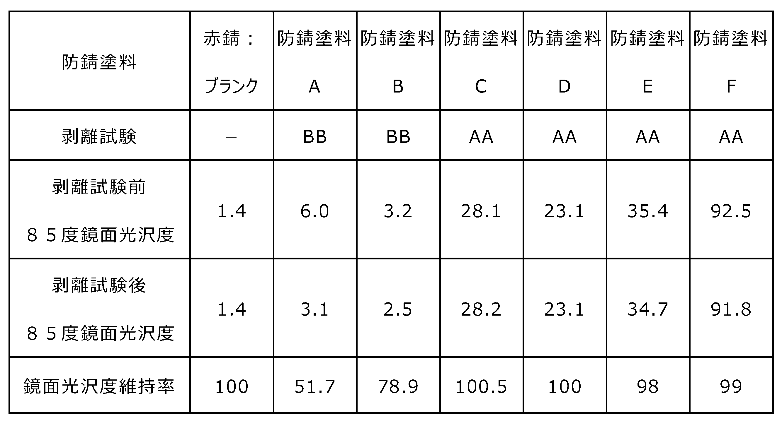
上記と同様に、発錆部(赤錆)を有する鋼板を準備した。該鋼板に対して、3種ケレンを実施した。3種ケレン後の鋼板は、旧塗膜の活膜(厚さ約150μm)と錆面とを含む素地調整面を有していた。鋼板の素地調整面に防錆塗料A~Fを用いて防錆処理を行い、厚さ約50μmの防錆塗膜を形成した。
厚さ300μmのポリエチレン層、ガラス網含有ポリエチレン層、厚さ300μmのポリエチレン層、厚さ1000μmのアクリル系複合粘着層(3M(登録商標) VHB(登録商標)テープ ガラス用・高透明性 Y-4910J)をこの順に備える粘着シートを準備した。アクリル系複合粘着層は、アクリル系粘着剤層、アクリル樹脂層およびアクリル系粘着剤層をこの順に備える。最外層のアクリル系粘着剤層の40℃での貯蔵弾性率(G’)は、0.369MPaであった。貯蔵弾性率は、JIS K7244-1:1998に準拠した動的粘弾性測定法(アタッチメントモード:圧縮モード、周波数:1Hz、温度:-50~200℃、昇温速度:5℃/分)にて、固体粘弾性測定装置(ティー・エイ・インスツルメント社製の固体粘弾性アナライザーRSA-III)を用いて測定した。
鋼板における防錆塗膜の形成面に、JIS Z0237:2022に準拠して、10mm幅の上記粘着シートを温度23℃、湿度50%RHの環境下で貼り付けた。この段階で、上記形成面に対する粘着シートの段差追従性を確認したところ、上記粘着シートは良好に段差に追従して密着していた。上記環境下にて3日間静置後に、300mm/minの速度で粘着シートの180度剥離を実施し、粘着シートの剥離状態を確認した。試験装置として、テンシロン万能試験機RTG-1250を用いた。剥離状態を確認したところ、アクリル系複合粘着層において凝集破壊したことを確認した。
本開示の鋼構造物の補修方法において用いられる接着シートの支持体の評価のため、さらなる試験を行った。試験においては、図2Bに示す層構成を有する積層体55を作製し、さらに積層体55を用いて図3に示す層構成を有する支持体52を作製した。そして、作製された積層体55及び支持体52の評価試験を行った。図2Bに示す例において、積層体55は、樹脂層62と、表面樹脂層63と、を厚さ方向にこの順に備えている。図3に示す例において、支持体52は、ガスバリアフィルム61と、樹脂層62と、表面樹脂層63と、を厚さ方向にこの順に備えている。支持体52は、さらにガスバリアフィルム61と樹脂層62との間に位置してガスバリアフィルム61と樹脂層62とを接着させる接着層64を備えている。
図2Bに示す積層体55及び図3に示す支持体52の作製は、以下の通りに行った。まず、ベース樹脂95質量部に対して、耐候剤マスターバッチ5質量部を混合して、樹脂組成物を得た。ベース樹脂としては、密度が0.901g/cm3、融点が93℃、190℃でのMFRが2.0g/10分である、メタロセン系直鎖状低密度ポリエチレン系樹脂(M-LLDPE)を用いた。耐候剤マスターバッチとしては、低密度ポリエチレン系樹脂100質量部に対して、HALS(ケミプロ化成社製「KEMISTAB62」)0.6質量部、第1の紫外線吸収剤3.5質量部、第2の紫外線吸収剤0.6質量部を混合したものを用いた。耐候剤マスターバッチの低密度ポリエチレン系樹脂の密度は0.880g/cm3であり、190℃でのMFR(メルトフローレート)は3.5g/10分であった。HALSとしては、ケミプロ化成社製の「KEMISTAB62」を用いた。第1の紫外線吸収剤としては、ケミプロ化成社製の「KEMISORB12」を用いた。第2の紫外線吸収剤としては、ケミプロ化成社製の「KEMISORB79」を用いた。
次に、φ30mm押出し機、200mm幅のTダイを有するフィルム成形機を用いて、押出し温度210℃で、上記樹脂組成物をシート化した。これによって、厚さ300μmの樹脂層62を形成した。このシート化を行うときの引き取り速度は、形成される樹脂層62の厚さが300μmとなるように調整した。Tダイ直下の冷却ロールとしては、表面粗さRz1.5μmのクロムメッキ仕上げの冷却ロールを使用した。Tダイ直下のゴムロールとしては、硬度70度のシリコーンゴムロールを使用した。樹脂層62は、着色されておらず、透明であった。
次に、樹脂層62の一面に、コロナ放電処理を施した。続いて、混合物100質量部と、硬化剤5質量部と、紫外線吸収剤20質量部と、希釈溶剤とを混合して、プライマー層用樹脂組成物を作製した。100質量部の混合物としては、ポリカーボネート系ウレタン-アクリル共重合体及びアクリルポリオールからなる混合物を用いた。5質量部の硬化剤としては、ヘキサメチレンジイソシアネートを用いた。作製されたプライマー層用樹脂組成物を、樹脂層62のコロナ放電処理を施した処理面に塗布した。プライマー層用樹脂組成物の塗布に際しては、処理面に、プライマー層用樹脂組成物をグラビア印刷法によって塗布して乾燥させた。これによって、樹脂層62の処理面上に厚さ4μmのプライマー層を形成した。
次に、ウレタンアクリレートオリゴマー100質量部と、紫外線吸収剤としてのヒドロキシフェニルトリアジン系紫外線吸収剤4部と、ヒンダードアミン系非反応性光安定剤3質量部と、を含んだ電離放射線硬化性樹脂組成物を作製した。作製された電離放射線硬化性樹脂組成物をプライマー層上に塗布して、プライマー層上に未硬化樹脂層を形成した。続いて、電子線を照射することで、当該未硬化樹脂層を硬化させた。電子線としては、加速電圧が165kV、照射線量が5Mrad(50kGy)の電子線を用いた。これによって、当該未硬化樹脂層から、厚さ5μmの表面樹脂層63を形成した。表面樹脂層63と樹脂層62とは、図2B及び図3には図示しないプライマー層を介して接着された。これによって、図2Bに示す積層体55を作製した。
さらに、樹脂層62の、プライマー層及び表面樹脂層63が形成された面とは反対側の面に、透明なウレタン樹脂系接着剤を塗布して乾燥させ、厚さ3μmの接着層64を形成した。さらに、ガスバリアフィルム61を用意した。ガスバリアフィルム61としては、IB-PET-UB(大日本印刷株式会社製)を用いた。IB-PET-UBは、樹脂フィルムと、蒸着膜であるガスバリア層と、を備えたガスバリアフィルム61であると言える。続いて、樹脂層62とガスバリアフィルム61とを、上記接着層64を介してドライラミネートすることによって接着させた。このとき、ガスバリアフィルム61のガスバリア層によって構成されている面と樹脂層62の面とが向かい合うように、樹脂層62とガスバリアフィルム61とを接着させた。以上により、支持体52を作製した。
<耐候性試験>
支持体52、及び支持体52を備える接着シート50は、耐候性を備えることが好ましい。具体的には、支持体52は、図1Dに示すように支持体52が防錆塗膜40を覆っているときに、紫外線から防錆塗膜40を保護できてもよい。特に、紫外線により防錆塗膜40に含まれる材料が変質することを抑制できてもよい。支持体52は、紫外線により防錆塗膜40が変色すること、特に黄変することを抑制できてもよい。支持体52は、紫外線により接着シート50に含まれる材料が変質しないように、紫外線に対する耐性を有していてもよい。上述したように、接着シート50の表面に上塗り塗膜が設けられている場合には、上塗り塗膜によって、防錆塗膜40及び接着シート50を紫外線から保護し得る。しかしながら、接着シート50の表面に上塗り塗膜を設けない場合も想定される。この場合に特に、支持体52が、防錆塗膜40に含まれる材料の紫外線による変質を抑制できることが好ましい。さらに、この場合に特に、支持体52が、紫外線に対する耐性を有することが好ましい。上述したように、支持体52は、添加剤として紫外線吸収剤を含んでもよい。この場合に、上述したように、表面樹脂層63が、紫外線吸収剤を含んでもよい。上述したように、図3に示すような支持体52の樹脂層62が、紫外線吸収剤を含んでもよい。上述したように、図3に示すような支持体52の、表面樹脂層63と樹脂層62とを接着するプライマー層が、紫外線吸収剤を含んでもよい。支持体52が紫外線吸収剤を含むことによって、紫外線から防錆塗膜40を保護できる。さらに、支持体52に、紫外線に対する耐性を付与できる。特に、表面樹脂層63が紫外線吸収剤を含むことによって、防錆塗膜40及び接着シート50の表面樹脂層63に覆われる部分を、表面樹脂層63によって紫外線から保護できる。
支持体52、及び支持体52を備える接着シート50は、耐候性を備えることが好ましい。具体的には、支持体52は、図1Dに示すように支持体52が防錆塗膜40を覆っているときに、紫外線から防錆塗膜40を保護できてもよい。特に、紫外線により防錆塗膜40に含まれる材料が変質することを抑制できてもよい。支持体52は、紫外線により防錆塗膜40が変色すること、特に黄変することを抑制できてもよい。支持体52は、紫外線により接着シート50に含まれる材料が変質しないように、紫外線に対する耐性を有していてもよい。上述したように、接着シート50の表面に上塗り塗膜が設けられている場合には、上塗り塗膜によって、防錆塗膜40及び接着シート50を紫外線から保護し得る。しかしながら、接着シート50の表面に上塗り塗膜を設けない場合も想定される。この場合に特に、支持体52が、防錆塗膜40に含まれる材料の紫外線による変質を抑制できることが好ましい。さらに、この場合に特に、支持体52が、紫外線に対する耐性を有することが好ましい。上述したように、支持体52は、添加剤として紫外線吸収剤を含んでもよい。この場合に、上述したように、表面樹脂層63が、紫外線吸収剤を含んでもよい。上述したように、図3に示すような支持体52の樹脂層62が、紫外線吸収剤を含んでもよい。上述したように、図3に示すような支持体52の、表面樹脂層63と樹脂層62とを接着するプライマー層が、紫外線吸収剤を含んでもよい。支持体52が紫外線吸収剤を含むことによって、紫外線から防錆塗膜40を保護できる。さらに、支持体52に、紫外線に対する耐性を付与できる。特に、表面樹脂層63が紫外線吸収剤を含むことによって、防錆塗膜40及び接着シート50の表面樹脂層63に覆われる部分を、表面樹脂層63によって紫外線から保護できる。
上述の通りに作製された図2Bに示す積層体55について、耐候性試験を行った。この耐候性試験においては、図4に示すような、防錆塗膜140が形成された鋼材110を用意した。防錆塗膜140の厚さは、約25μmであった。続いて、図5に示すように、接着層154を介して積層体55と防錆塗膜140とを接着させ、耐候性試験用の試料とした。このとき、防錆塗膜140の面と積層体55の樹脂層62によって形成されている面とが向かい合うように、積層体55と防錆塗膜140とを接着させた。接着層154としては、アクリル系粘着剤を用いた。接着層154の厚さは、80μmであった。
続いて、耐候性試験用の試料に対して、408時間の耐候性試験を行った。耐候性試験は、耐候性試験装置を用いて、実施された。408時間の耐候性試験は、次のように実施した。耐候性試験用の試料に対し、図5における表面樹脂層63によって構成されている面の側から20時間紫外線を照射する照射工程と、4時間の結露工程と、を1サイクルとして、408時間に達するまでサイクルを繰り返し実施した。照射工程後で結露工程を開始する前と、結露工程後で照射工程を開始する前とにおいて、30秒のシャワー工程を実施した。シャワー工程では、耐候性試験装置に保持されたサンプルを水のシャワーに晒した。
耐候性試験装置として、岩崎電気社製の超促進耐候性試験装置「アイ スーパー UVテスター SUV-W261」を用いた。耐候性試験装置に含まれるUVランプ、ランプジャケット、及び照度計は、次の通りとした。
・UVランプ:商品名:M04-L21WB/SUV、岩崎電気社製
・ランプジャケット:商品名:WJ50-SUV、岩崎電気社製
・照度計:商品名:UVD-365PD、岩崎電気社製
・UVランプ:商品名:M04-L21WB/SUV、岩崎電気社製
・ランプジャケット:商品名:WJ50-SUV、岩崎電気社製
・照度計:商品名:UVD-365PD、岩崎電気社製
照射工程の条件は、次の通りとした。
<照射条件>
・ブラックパネル温度:63℃
・照度:100mW/cm2
・槽内湿度:50%RH
・時間:20時間
<照射条件>
・ブラックパネル温度:63℃
・照度:100mW/cm2
・槽内湿度:50%RH
・時間:20時間
結露工程の条件は、次の通りとした。
<結露条件>
・照度:0mW/cm2
・槽内湿度:98%RH
・時間:4時間
<結露条件>
・照度:0mW/cm2
・槽内湿度:98%RH
・時間:4時間
その上で、耐候性試験を行う前後における防錆塗膜140の色差ΔEを測定した。測定される色差ΔEは、JIS Z8781:2013に規定するL*a*b*表色系における、耐候性試験前の色をL*
1a*
1b*
1、耐候性試験後の色をL*
2a*
2b*
2として、以下の式(1)~(4)によって規定した。

耐候性試験前の色L*
1a*
1b*
1、及び耐候性試験後の色L*
2a*
2b*
2は、積層体55を介して防錆塗膜140を観察したときの色とした。
さらに、比較例の試料として、図4に示すような、防錆塗膜140が形成された鋼材110を用意した。比較例の試料について、防錆塗膜140を積層体55によって覆うことなく、上述した図5に示す試料と同様の方法によって、408時間の耐候性試験を行い、耐候性試験を行う前後における防錆塗膜140の色差ΔEを測定した。比較例の試料の耐候性試験の照射工程においては、試料の防錆塗膜140によって構成されている面の側から紫外線を照射した。
色差ΔEの測定の結果、図5に示すように防錆塗膜140が積層体55に覆われている試料においては、紫外線を照射する前後における色差ΔEは4.3であった。これに対して、比較例の防錆塗膜140が積層体55に覆われていない試料においては、紫外線を照射する前後における色差ΔEは14.7であった。このことから、図5に示すように防錆塗膜140を積層体55で覆うことによって、防錆塗膜140を紫外線から保護して、防錆塗膜140の変色を抑制できることがわかった。この結果から、積層体55に加えてさらにガスバリアフィルム61及び接着層64を備える支持体52で防錆塗膜140を覆った場合にも、防錆塗膜140を紫外線から保護して、防錆塗膜140の変色を抑制できることが明らかとなった。
<耐湿潤冷熱繰返し性の試験>
支持体52は、湿潤冷熱繰返しへの耐性を有することが好ましい。より具体的には、JIS K5659:2018の7.18に記載の「耐湿潤冷熱繰り返し性の試験」において、「湿潤冷熱繰返しに耐える」と評価されることが好ましい。
支持体52は、湿潤冷熱繰返しへの耐性を有することが好ましい。より具体的には、JIS K5659:2018の7.18に記載の「耐湿潤冷熱繰り返し性の試験」において、「湿潤冷熱繰返しに耐える」と評価されることが好ましい。
上述の通りに作製された図3に示す支持体52について、JIS K5659:2018の7.18に記載の「耐湿潤冷熱繰り返し性の試験」を行った。この結果、支持体52は、「湿潤冷熱繰返しに耐える」と評価された。具体的には、JIS K5659:2018の7.16のa)及びb)に記載の方法によって、支持体52から2枚の試験片を作製した。作製された試験片2枚を23℃±1℃の水中に18時間浸した後、直ちに-20±3℃に保った恒温槽で3時間冷却し、次に、50±3℃に保った別の恒温槽で3時間加湿する、という操作を10回繰り返した。この試験片2枚について、目視によって観察した。このとき、塗膜に膨れ、割れ及び剥がれは認められなかった。さらに、JIS K5659:2018の7.18のb)2)に記載の方法によって光沢保持率を算出したところ、80%以上となった。
上述した操作の10回の繰り返しを経た2枚の試験片を目視によって観察したところ、支持体52に含まれる層の間での剥離は観察されなかった。
上述した操作の10回の繰り返しを経た試験片について、JIS K6854-3:1999の「接着剤-はく離接着強さ試験方法-第3部:T形はく離」に準拠して、T形はく離試験を行った。これによって、接着層64におけるはく離接着強さに関して、極大点強度を測定した。試験中に試験片の材料が破断した場合には破断強度、試験中に試験片の材料が破断しなかった場合には最大剥離強度を、極大点強度として測定した。さらに、比較例として、上述した操作の10回の繰り返しを行っていない試験片について、上述した操作の10回の繰り返しを経た試験片と同様のT形はく離試験を行った。これによって、比較例の試験片についても、接着層64におけるはく離接着強さに関して、極大点強度を測定した。この結果、上述した操作の10回の繰り返しを経た試験片の極大点強度は、比較例の試験片の極大点強度の90%以上であった。以上より、図3に示す支持体52について耐湿潤冷熱繰り返し性の試験を行ったとしても、接着層64におけるはく離接着強さの低下は小さいことがわかった。
<上塗り適合性の試験>
上述したように、接着シート50の表面に上塗り塗料を塗布して、上塗り塗膜を形成することが望まれる場合がある。この場合、接着シート50の表面を構成する支持体52は、上塗り適合性を有することが好ましい。本明細書において、支持体52の「上塗り適合性」とは、支持体52の表面に支障なく上塗り塗料を塗布して上塗り塗膜を形成できる性質を意味する。
上述したように、接着シート50の表面に上塗り塗料を塗布して、上塗り塗膜を形成することが望まれる場合がある。この場合、接着シート50の表面を構成する支持体52は、上塗り適合性を有することが好ましい。本明細書において、支持体52の「上塗り適合性」とは、支持体52の表面に支障なく上塗り塗料を塗布して上塗り塗膜を形成できる性質を意味する。
上述の通りに作製された図3に示す支持体52について、上塗り適合性の試験を行った。この上塗り適合性の試験においては、支持体52から、150mm×70mmの大きさの、2枚の試験板を作製した。試験板1枚の、表面樹脂層63によって構成されている面上に、上塗り塗料を塗布した。上塗り塗料の塗布には、ベーカー式アプリケータを用いた。これによって試験片を作製した。上塗り塗料を塗布した試験板とは別の試験板1枚は、上塗り塗料を塗布せずに原状試験片とした。
作製された試験片を用いて、JIS K5551:2018の7.11のc)に記載の、「上塗り適合性」に関する「評価及び判定」に記載の方法に従って、支持体52が上塗り適合性を有するかを判定した。すなわち、以下の1)~3)の3点を確認した。
1)試験板1枚の表面樹脂層63によって構成されている面上に上塗り塗料を塗布するときに、上塗り作業に支障がない。
2)上塗り後(表面樹脂層63によって構成されている面上への上塗り塗料の塗布後)48時間置いて、形成された上塗り塗膜の外観を目視によって観察したとき、上塗り塗料にはじき、割れ、穴膨れ及び剥がれを認めない。
3)上塗り後48時間置いた試験片と、同時に作製した原状試験片とを比べ、指触によって確認したときに粘着の程度が大きくなく、且つ目視によって確認したときにしわの程度が大きくない。
上記の1)~3)の3点の全てを満足するときに、支持体52の表面に上塗り塗料を塗布して上塗り塗膜を形成することに「支障がない」とした。すなわち、上記の1)~3)の3点の全てを満足するときに、支持体52が上塗り適合性を有すると判定した。
上述した上塗り適合性の試験を、上塗り塗料として汚れ防止形フッ素樹脂上塗塗料(大日本塗料株式会社製、製品名「Vフロン♯100Hスマイル上塗IG」)を用いて行った。このとき、上塗り塗膜の目標膜厚は25μmとした。形成された上塗り塗膜の実測膜厚は23.8μmであった。さらに、上述した上塗り適合性の試験を、上塗り塗料として弱溶剤超厚膜エポキシ樹脂塗料(大日本塗料株式会社製、製品名「エポニックスH-Rスマイル」)を用いて行った。このとき、上塗り塗膜の目標膜厚は150μmとした。形成された上塗り塗膜の実測膜厚は164.5μmであった。
上塗り適合性の試験の結果、上塗り塗料として汚れ防止形フッ素樹脂上塗塗料、弱溶剤超厚膜エポキシ樹脂塗料のいずれを用いた場合であっても、支持体52の表面に上塗り塗料を塗布して上塗り塗膜を形成することに支障がないと判定された。すなわち、上塗り塗料として汚れ防止形フッ素樹脂上塗塗料、弱溶剤超厚膜エポキシ樹脂塗料のいずれを用いた場合であっても、支持体52が上塗り適合性を有すると判定された。
さらに、上塗り適合性の試験において作製した、上塗り塗料を塗布し、上塗り後48時間置いた試験片の上塗り塗膜に対して、上述した90度テープ剥離試験を行った。すなわち、JIS Z1522:2009に適合する24mm幅セロハン粘着テープの巻きから、温度23℃、湿度50%RH環境下にて25cm分を巻き出した。持ち手を作製するために10cmの粘着面同士を貼り合わせた。この状態で、粘着面5cmを、上塗り塗膜の表面に質量2kgの圧着ローラー2往復にて付着させた上で、更に空気が介在しないように再度指圧にて付着させた。次いで、上塗り塗膜の表面に対して90度方向に手動にて5cm/sの速度でセロハン粘着テープの強剥離を1回実施した。上記セロハン粘着テープとして、セロテープ(登録商標)(ニチバン製、型番No.405-1P、24mm幅、粘着力:3.93N/10mm、引張強さ:41.6N/10mm、伸び:23%、該物性値はいずれもカタログ値)を用いた。当該製品を使用できない場合は、当該製品と同等の粘着力を有する、JIS Z1522:2009に適合する24mm幅セロハン粘着テープを用いることで、上塗り塗膜に対して90度テープ剥離試験を行える。
上塗り塗膜に対する90度テープ剥離試験の結果、セロハン粘着テープの強剥離を1回実施しても、上塗り塗膜の剥離は生じなかった。
<像鮮明度>
接着シートの表面への外部の物体の映り込みを抑制する観点からは、接着シートの第1面での反射法による像鮮明度(%)が小さいことが好ましい。上述の通りに作製された図2Bに示す積層体55について、像鮮明度測定試験を行った。この像鮮明度測定試験においては、耐候性試験において上述したのと同様の方法によって、図5に示すような、鋼材110と、鋼材110上に形成された防錆塗膜140と、防錆塗膜140を覆う積層体55とを有する試料を作製した。防錆塗膜140の形成には、上述した防錆塗料Fを使用した。
接着シートの表面への外部の物体の映り込みを抑制する観点からは、接着シートの第1面での反射法による像鮮明度(%)が小さいことが好ましい。上述の通りに作製された図2Bに示す積層体55について、像鮮明度測定試験を行った。この像鮮明度測定試験においては、耐候性試験において上述したのと同様の方法によって、図5に示すような、鋼材110と、鋼材110上に形成された防錆塗膜140と、防錆塗膜140を覆う積層体55とを有する試料を作製した。防錆塗膜140の形成には、上述した防錆塗料Fを使用した。
この試料の、表面樹脂層63によって構成されている面での反射法による像鮮明度(%)を測定した。像鮮明度(%)は、JIS K7374:2007に準拠して測定した。像鮮明度(%)として、くし幅1.0mmのときの像鮮明度(%)を測定した。測定時の、入射面(試料の、表面樹脂層63によって構成されている面)に入射させる光の入射角は60°とした。像鮮明度(%)の測定には、スガ試験機株式会社製の写像性測定器ICM-1Tを用いた。
像鮮明度(%)の測定の結果、12.8%との測定結果を得た。このことから、積層体55の表面樹脂層63によって構成されている面での、くし幅1.0mmのときの像鮮明度が、20%以下に抑えられていることがわかった。
本開示は、例えば以下の[1]~[13]に関する。
[1]劣化部を有する鋼構造物の補修方法であって、支持体、および前記支持体の一方の表面上に設けられた接着層を備える接着シートを準備する第1工程と、前記鋼構造物の前記劣化部に対して素地調整を行い、活膜を有してもよい素地調整面を形成する第2工程と、前記鋼構造物の前記素地調整面に防錆処理を行い、防錆処理面を形成する第3工程と、前記鋼構造物の前記防錆処理面上に、前記接着シートを配置する第4工程と、含む、鋼構造物の補修方法。
[2]前記第2工程が、前記鋼構造物の劣化部に対して、3種ケレンの素地調整を少なくとも行う工程である、前記[1]に記載の鋼構造物の補修方法。
[3]前記第3工程が、前記鋼構造物の前記素地調整面に防錆塗料を塗布して防錆塗膜を形成する工程である、前記[1]または[2]に記載の鋼構造物の補修方法。
[4]前記防錆塗料が、2液硬化型防錆塗料である、前記[3]に記載の鋼構造物の補修方法。
[5]前記防錆塗膜の面である防錆塗膜面に対して90度テープ剥離試験を実施する前の前記防錆塗膜面の85度鏡面光沢度をGsbと記載し、前記防錆塗膜面に対して90度テープ剥離試験を実施した後の前記防錆塗膜面の85度鏡面光沢度をGsaと記載した場合に、維持率(Gsa×100/Gsb)が、95%以上である、前記[3]または[4]に記載の鋼構造物の補修方法。
[6]前記第3工程と前記第4工程との間に、前記防錆処理面上に被覆樹脂層を形成する第3a工程をさらに含む、前記[1]~[5]のいずれか一つに記載の鋼構造物の補修方法。
[7]前記防錆処理面上に配置された前記接着シートの表面に上塗り塗膜を形成する第5工程をさらに含む、前記[1]~[6]のいずれか一つに記載の鋼構造物の補修方法。
[8]前記接着シートが、第1の接着層と、基材層と、第2の接着層と、を厚さ方向にこの順に備える複合接着層を備える、前記[1]~[7]のいずれか一つに記載の鋼構造物の補修方法。
[9]前記接着シートの前記支持体が、ガスバリア層を備える、前記[1]~[8]のいずれか一つに記載の鋼構造物の補修方法。
[10]前記接着シートの、JIS K7126-2:2006に準拠して、温度23℃、湿度60%RH環境下において測定される酸素透過度が、6.57cc/(m2・day・atm)以下である、前記[9]に記載の鋼構造物の補修方法。
[11]前記接着シートの、JIS K7129-2:2019に準拠して、温度40℃、湿度90%RH環境下において測定される水蒸気透過度が、3.0g/(m2・day)以下である、前記[9]または[10]に記載の鋼構造物の補修方法。
[12]前記接着シートの全光線透過率が、70%以上である、前記[1]~[11]のいずれか一つに記載の鋼構造物の補修方法。
[13]前記接着シートのヘイズが、97%以上である、前記[12]に記載の鋼構造物の補修方法。
[14]前記接着シートは、前記接着シートを前記鋼構造物の前記防錆処理面上に配置するときに前記鋼構造物に向けられる面とは反対側の面である、第1面を有し、
前記接着シートの前記第1面での反射法による像鮮明度(%)が、くし幅1.0mmのときに20%以下である、前記[12]または[13]に記載の鋼構造物の補修方法。
[15]劣化部を有する鋼構造物に対して、前記[1]~[14]のいずれか一つに記載の鋼構造物の補修方法を適用して、補修された鋼構造物を製造する、鋼構造物の製造方法。
[16]支持体、および前記支持体の一方の表面に設けられた接着層を備える、鋼構造物の補修用接着シートであって、劣化部を有する鋼構造物の前記劣化部に対して素地調整および防錆処理が行われた防錆処理面上に配置するための、鋼構造物の補修用接着シート。
[17]前記接着シートが、第1の接着層と、基材層と、第2の接着層と、を厚さ方向にこの順に備える複合接着層を備える、前記[16]に記載の鋼構造物の補修用接着シート。
10・・・鋼材、20・・・補修前塗膜(旧塗膜)、22・・・活膜、30・・・錆、40・・・防錆塗膜、50・・・接着シート、52・・・支持体、54・・・接着層
Claims (15)
- 劣化部を有する鋼構造物の補修方法であって、支持体、および前記支持体の一方の表面上に設けられた接着層を備える接着シートを準備する第1工程と、
前記鋼構造物の前記劣化部に対して素地調整を行い、活膜を有してもよい素地調整面を形成する第2工程と、
前記鋼構造物の前記素地調整面に防錆処理を行い、防錆処理面を形成する第3工程と、
前記鋼構造物の前記防錆処理面上に、前記接着シートを配置する第4工程と、
を含む、鋼構造物の補修方法。 - 前記第2工程が、前記鋼構造物の劣化部に対して、3種ケレンの素地調整を少なくとも行う工程である、請求項1に記載の鋼構造物の補修方法。
- 前記第3工程が、前記鋼構造物の前記素地調整面に防錆塗料を塗布して防錆塗膜を形成する工程である、請求項1に記載の鋼構造物の補修方法。
- 前記防錆塗料が、2液硬化型防錆塗料である、請求項3に記載の鋼構造物の補修方法。
- 前記防錆塗膜の面である防錆塗膜面に対して90度テープ剥離試験を実施する前の前記防錆塗膜面の85度鏡面光沢度をGsbと記載し、前記防錆塗膜面に対して90度テープ剥離試験を実施した後の前記防錆塗膜面の85度鏡面光沢度をGsaと記載した場合に、維持率(Gsa×100/Gsb)が、95%以上である、請求項3に記載の鋼構造物の補修方法。
- 前記第3工程と前記第4工程との間に、前記防錆処理面上に被覆樹脂層を形成する第3a工程をさらに含む、請求項1に記載の鋼構造物の補修方法。
- 前記防錆処理面上に配置された前記接着シートの表面に上塗り塗膜を形成する第5工程をさらに含む、請求項1に記載の鋼構造物の補修方法。
- 前記接着シートの前記支持体が、ガスバリア層を備える、請求項1に記載の鋼構造物の補修方法。
- 前記接着シートの、JIS K7126-2:2006に準拠して、温度23℃、湿度60%RH環境下において測定される酸素透過度が、6.57cc/(m2・day・atm)以下である、請求項8に記載の鋼構造物の補修方法。
- 前記接着シートの、JIS K7129-2:2019に準拠して、温度40℃、湿度90%RH環境下において測定される水蒸気透過度が、3.0g/(m2・day)以下である、請求項8に記載の鋼構造物の補修方法。
- 前記接着シートの全光線透過率が、70%以上である、請求項1に記載の鋼構造物の補修方法。
- 前記接着シートのヘイズが、97%以上である、請求項11に記載の鋼構造物の補修方法。
- 前記接着シートは、前記接着シートを前記鋼構造物の前記防錆処理面上に配置するときに前記鋼構造物に向けられる面とは反対側の面である、第1面を有し、
前記接着シートの前記第1面での反射法による像鮮明度(%)が、くし幅1.0mmのときに20%以下である、請求項11に記載の鋼構造物の補修方法。 - 劣化部を有する鋼構造物に対して、請求項1~13のいずれか一項に記載の鋼構造物の補修方法を適用して、補修された鋼構造物を製造する、鋼構造物の製造方法。
- 支持体、および前記支持体の一方の表面に設けられた接着層を備える、鋼構造物の補修用接着シートであって、劣化部を有する鋼構造物の前記劣化部に対して素地調整および防錆処理が行われた防錆処理面上に配置するための、鋼構造物の補修用接着シート。
Priority Applications (2)
| Application Number | Priority Date | Filing Date | Title |
|---|---|---|---|
| JP2024551618A JP7683830B2 (ja) | 2023-03-15 | 2024-03-14 | 鋼構造物の補修方法及び補修された鋼構造物 |
| JP2025079931A JP2025122017A (ja) | 2023-03-15 | 2025-05-12 | 鋼構造物の補修方法及び鋼構造物の補修用接着シート |
Applications Claiming Priority (4)
| Application Number | Priority Date | Filing Date | Title |
|---|---|---|---|
| JP2023041164 | 2023-03-15 | ||
| JP2023-041164 | 2023-03-15 | ||
| JP2023206365 | 2023-12-06 | ||
| JP2023-206365 | 2023-12-06 |
Publications (1)
| Publication Number | Publication Date |
|---|---|
| WO2024190890A1 true WO2024190890A1 (ja) | 2024-09-19 |
Family
ID=92755864
Family Applications (1)
| Application Number | Title | Priority Date | Filing Date |
|---|---|---|---|
| PCT/JP2024/010132 Ceased WO2024190890A1 (ja) | 2023-03-15 | 2024-03-14 | 鋼構造物の補修方法及び鋼構造物の補修用接着シート |
Country Status (2)
| Country | Link |
|---|---|
| JP (2) | JP7683830B2 (ja) |
| WO (1) | WO2024190890A1 (ja) |
Cited By (1)
| Publication number | Priority date | Publication date | Assignee | Title |
|---|---|---|---|---|
| WO2025206403A1 (ja) * | 2024-03-29 | 2025-10-02 | 大日本印刷株式会社 | 被覆シート、構造物、及び構造物の補修方法 |
Citations (7)
| Publication number | Priority date | Publication date | Assignee | Title |
|---|---|---|---|---|
| JP2000063741A (ja) * | 1998-08-12 | 2000-02-29 | Iwakiri:Kk | 速乾性防錆塗料 |
| JP2006336393A (ja) * | 2005-06-06 | 2006-12-14 | Anan Denki Kk | 繊維強化樹脂シートによる部材の補修方法 |
| JP4068033B2 (ja) * | 2003-09-01 | 2008-03-26 | 株式会社佐伯建設 | 鋼構造物の補強方法 |
| JP6427624B1 (ja) * | 2017-05-16 | 2018-11-21 | 阿南電機株式会社 | 鋼構造物の補修方法 |
| JP2019157603A (ja) * | 2018-03-16 | 2019-09-19 | 積水化学工業株式会社 | 鋼構造物補修方法 |
| JP2021006675A (ja) * | 2019-06-27 | 2021-01-21 | ショーボンド建設株式会社 | 鋼材の防錆防食方法、防錆防食処理鋼材、鋼材の保護補修方法及び粘着シート |
| JP2022133053A (ja) * | 2021-03-01 | 2022-09-13 | Mccアドバンスドモールディングス株式会社 | 防食用ラミネートフィルムおよび防食テープ |
Family Cites Families (2)
| Publication number | Priority date | Publication date | Assignee | Title |
|---|---|---|---|---|
| JPS6190774A (ja) * | 1984-10-06 | 1986-05-08 | Nitto Electric Ind Co Ltd | 防食層欠陥部の補修方法 |
| JP6376912B2 (ja) | 2014-09-10 | 2018-08-22 | 東京電力ホールディングス株式会社 | 亜鉛めっき鋼材用の錆処理剤及びそれを用いた補修方法 |
-
2024
- 2024-03-14 WO PCT/JP2024/010132 patent/WO2024190890A1/ja not_active Ceased
- 2024-03-14 JP JP2024551618A patent/JP7683830B2/ja active Active
-
2025
- 2025-05-12 JP JP2025079931A patent/JP2025122017A/ja active Pending
Patent Citations (7)
| Publication number | Priority date | Publication date | Assignee | Title |
|---|---|---|---|---|
| JP2000063741A (ja) * | 1998-08-12 | 2000-02-29 | Iwakiri:Kk | 速乾性防錆塗料 |
| JP4068033B2 (ja) * | 2003-09-01 | 2008-03-26 | 株式会社佐伯建設 | 鋼構造物の補強方法 |
| JP2006336393A (ja) * | 2005-06-06 | 2006-12-14 | Anan Denki Kk | 繊維強化樹脂シートによる部材の補修方法 |
| JP6427624B1 (ja) * | 2017-05-16 | 2018-11-21 | 阿南電機株式会社 | 鋼構造物の補修方法 |
| JP2019157603A (ja) * | 2018-03-16 | 2019-09-19 | 積水化学工業株式会社 | 鋼構造物補修方法 |
| JP2021006675A (ja) * | 2019-06-27 | 2021-01-21 | ショーボンド建設株式会社 | 鋼材の防錆防食方法、防錆防食処理鋼材、鋼材の保護補修方法及び粘着シート |
| JP2022133053A (ja) * | 2021-03-01 | 2022-09-13 | Mccアドバンスドモールディングス株式会社 | 防食用ラミネートフィルムおよび防食テープ |
Cited By (1)
| Publication number | Priority date | Publication date | Assignee | Title |
|---|---|---|---|---|
| WO2025206403A1 (ja) * | 2024-03-29 | 2025-10-02 | 大日本印刷株式会社 | 被覆シート、構造物、及び構造物の補修方法 |
Also Published As
| Publication number | Publication date |
|---|---|
| JPWO2024190890A1 (ja) | 2024-09-19 |
| JP2025122017A (ja) | 2025-08-20 |
| JP7683830B2 (ja) | 2025-05-27 |
Similar Documents
| Publication | Publication Date | Title |
|---|---|---|
| JP7534143B2 (ja) | 共硬化性ペイント用フィルムの使用による、複合基板からの下地フィルム及びプライマーの排除 | |
| JP2025122017A (ja) | 鋼構造物の補修方法及び鋼構造物の補修用接着シート | |
| JP2018193739A (ja) | 鋼構造物の補修方法 | |
| CA2823251A1 (en) | Mechanical and anticorrosive protection vinyl tape | |
| JP4424536B2 (ja) | 重防食積層被膜、重防食積層被膜付き鋼材および重防食積層被膜の形成方法 | |
| JP2025090393A (ja) | 被覆シート、鋼構造物、及び鋼構造物の補修方法 | |
| US6080254A (en) | Method of protecting metals against corrosion | |
| JP2025062572A (ja) | 被覆シート、鋼構造物、及び鋼構造物の補修方法 | |
| JP7200026B2 (ja) | 鋼材の防錆補修方法、鉄塔の防錆補修方法及び防錆補修鋼材 | |
| WO2025206403A1 (ja) | 被覆シート、構造物、及び構造物の補修方法 | |
| JP2026054362A (ja) | 鋼構造物の被覆方法、被覆体付き鋼構造物の製造方法、被覆シート及び被覆体付き鋼構造物 | |
| JP2026054386A (ja) | 鋼構造物、鋼構造物の補修方法、及び鋼構造物の製造方法 | |
| JP6913211B1 (ja) | 構造物表面の保護工法 | |
| Aakkula et al. | DIARC plasma coating for reliable and durable structural bonding of metals | |
| JP2024163159A (ja) | 防食テープ | |
| JP2005035827A (ja) | コンクリート構造物の保護方法 | |
| JP3219028U (ja) | 建築構造物の外装材に対する塗装による補修・改修処理層の積層構造 | |
| JP2019166815A (ja) | 防食シート及びコンクリート構造物を保護する方法 | |
| US20080241399A1 (en) | Method of coating and coated sheet piling sections | |
| US11952512B2 (en) | Chemical process for stripping surfaces | |
| CA2431599C (en) | Oil tank protective coating | |
| JP5652989B2 (ja) | 旧塗膜の補修塗装法 | |
| JP2018162651A (ja) | 建築構造物における塗装補修方法 | |
| Tombaugh et al. | Premature failure of an intumescent coating: truth and consequences | |
| JP2020101033A (ja) | 鋼構造物の溶接部を保護又は補修する方法 |
Legal Events
| Date | Code | Title | Description |
|---|---|---|---|
| WWE | Wipo information: entry into national phase |
Ref document number: 2024551618 Country of ref document: JP |
|
| 121 | Ep: the epo has been informed by wipo that ep was designated in this application |
Ref document number: 24770992 Country of ref document: EP Kind code of ref document: A1 |
|
| NENP | Non-entry into the national phase |
Ref country code: DE |
|
| 122 | Ep: pct application non-entry in european phase |
Ref document number: 24770992 Country of ref document: EP Kind code of ref document: A1 |