WO2024190802A1 - 二次電池 - Google Patents
二次電池 Download PDFInfo
- Publication number
- WO2024190802A1 WO2024190802A1 PCT/JP2024/009655 JP2024009655W WO2024190802A1 WO 2024190802 A1 WO2024190802 A1 WO 2024190802A1 JP 2024009655 W JP2024009655 W JP 2024009655W WO 2024190802 A1 WO2024190802 A1 WO 2024190802A1
- Authority
- WO
- WIPO (PCT)
- Prior art keywords
- view
- protrusion
- plan
- protrusions
- uneven
- Prior art date
- Legal status (The legal status is an assumption and is not a legal conclusion. Google has not performed a legal analysis and makes no representation as to the accuracy of the status listed.)
- Ceased
Links
Images








Classifications
-
- H—ELECTRICITY
- H01—ELECTRIC ELEMENTS
- H01M—PROCESSES OR MEANS, e.g. BATTERIES, FOR THE DIRECT CONVERSION OF CHEMICAL ENERGY INTO ELECTRICAL ENERGY
- H01M50/00—Constructional details or processes of manufacture of the non-active parts of electrochemical cells other than fuel cells, e.g. hybrid cells
- H01M50/50—Current conducting connections for cells or batteries
- H01M50/543—Terminals
- H01M50/552—Terminals characterised by their shape
- H01M50/553—Terminals adapted for prismatic, pouch or rectangular cells
- H01M50/557—Plate-shaped terminals
-
- H—ELECTRICITY
- H01—ELECTRIC ELEMENTS
- H01M—PROCESSES OR MEANS, e.g. BATTERIES, FOR THE DIRECT CONVERSION OF CHEMICAL ENERGY INTO ELECTRICAL ENERGY
- H01M50/00—Constructional details or processes of manufacture of the non-active parts of electrochemical cells other than fuel cells, e.g. hybrid cells
- H01M50/50—Current conducting connections for cells or batteries
- H01M50/531—Electrode connections inside a battery casing
- H01M50/533—Electrode connections inside a battery casing characterised by the shape of the leads or tabs
-
- H—ELECTRICITY
- H01—ELECTRIC ELEMENTS
- H01M—PROCESSES OR MEANS, e.g. BATTERIES, FOR THE DIRECT CONVERSION OF CHEMICAL ENERGY INTO ELECTRICAL ENERGY
- H01M50/00—Constructional details or processes of manufacture of the non-active parts of electrochemical cells other than fuel cells, e.g. hybrid cells
- H01M50/50—Current conducting connections for cells or batteries
- H01M50/531—Electrode connections inside a battery casing
- H01M50/536—Electrode connections inside a battery casing characterised by the method of fixing the leads to the electrodes, e.g. by welding
-
- H—ELECTRICITY
- H01—ELECTRIC ELEMENTS
- H01M—PROCESSES OR MEANS, e.g. BATTERIES, FOR THE DIRECT CONVERSION OF CHEMICAL ENERGY INTO ELECTRICAL ENERGY
- H01M50/00—Constructional details or processes of manufacture of the non-active parts of electrochemical cells other than fuel cells, e.g. hybrid cells
- H01M50/50—Current conducting connections for cells or batteries
- H01M50/531—Electrode connections inside a battery casing
- H01M50/538—Connection of several leads or tabs of wound or folded electrode stacks
-
- H—ELECTRICITY
- H01—ELECTRIC ELEMENTS
- H01M—PROCESSES OR MEANS, e.g. BATTERIES, FOR THE DIRECT CONVERSION OF CHEMICAL ENERGY INTO ELECTRICAL ENERGY
- H01M50/00—Constructional details or processes of manufacture of the non-active parts of electrochemical cells other than fuel cells, e.g. hybrid cells
- H01M50/50—Current conducting connections for cells or batteries
- H01M50/531—Electrode connections inside a battery casing
- H01M50/54—Connection of several leads or tabs of plate-like electrode stacks, e.g. electrode pole straps or bridges
-
- H—ELECTRICITY
- H01—ELECTRIC ELEMENTS
- H01M—PROCESSES OR MEANS, e.g. BATTERIES, FOR THE DIRECT CONVERSION OF CHEMICAL ENERGY INTO ELECTRICAL ENERGY
- H01M50/00—Constructional details or processes of manufacture of the non-active parts of electrochemical cells other than fuel cells, e.g. hybrid cells
- H01M50/50—Current conducting connections for cells or batteries
- H01M50/543—Terminals
- H01M50/547—Terminals characterised by the disposition of the terminals on the cells
- H01M50/55—Terminals characterised by the disposition of the terminals on the cells on the same side of the cell
-
- H—ELECTRICITY
- H01—ELECTRIC ELEMENTS
- H01M—PROCESSES OR MEANS, e.g. BATTERIES, FOR THE DIRECT CONVERSION OF CHEMICAL ENERGY INTO ELECTRICAL ENERGY
- H01M50/00—Constructional details or processes of manufacture of the non-active parts of electrochemical cells other than fuel cells, e.g. hybrid cells
- H01M50/50—Current conducting connections for cells or batteries
- H01M50/543—Terminals
- H01M50/552—Terminals characterised by their shape
- H01M50/553—Terminals adapted for prismatic, pouch or rectangular cells
-
- H—ELECTRICITY
- H01—ELECTRIC ELEMENTS
- H01M—PROCESSES OR MEANS, e.g. BATTERIES, FOR THE DIRECT CONVERSION OF CHEMICAL ENERGY INTO ELECTRICAL ENERGY
- H01M50/00—Constructional details or processes of manufacture of the non-active parts of electrochemical cells other than fuel cells, e.g. hybrid cells
- H01M50/50—Current conducting connections for cells or batteries
- H01M50/543—Terminals
- H01M50/562—Terminals characterised by the material
-
- H—ELECTRICITY
- H01—ELECTRIC ELEMENTS
- H01M—PROCESSES OR MEANS, e.g. BATTERIES, FOR THE DIRECT CONVERSION OF CHEMICAL ENERGY INTO ELECTRICAL ENERGY
- H01M50/00—Constructional details or processes of manufacture of the non-active parts of electrochemical cells other than fuel cells, e.g. hybrid cells
- H01M50/50—Current conducting connections for cells or batteries
- H01M50/543—Terminals
- H01M50/564—Terminals characterised by their manufacturing process
- H01M50/566—Terminals characterised by their manufacturing process by welding, soldering or brazing
-
- Y—GENERAL TAGGING OF NEW TECHNOLOGICAL DEVELOPMENTS; GENERAL TAGGING OF CROSS-SECTIONAL TECHNOLOGIES SPANNING OVER SEVERAL SECTIONS OF THE IPC; TECHNICAL SUBJECTS COVERED BY FORMER USPC CROSS-REFERENCE ART COLLECTIONS [XRACs] AND DIGESTS
- Y02—TECHNOLOGIES OR APPLICATIONS FOR MITIGATION OR ADAPTATION AGAINST CLIMATE CHANGE
- Y02E—REDUCTION OF GREENHOUSE GAS [GHG] EMISSIONS, RELATED TO ENERGY GENERATION, TRANSMISSION OR DISTRIBUTION
- Y02E60/00—Enabling technologies; Technologies with a potential or indirect contribution to GHG emissions mitigation
- Y02E60/10—Energy storage using batteries
-
- Y—GENERAL TAGGING OF NEW TECHNOLOGICAL DEVELOPMENTS; GENERAL TAGGING OF CROSS-SECTIONAL TECHNOLOGIES SPANNING OVER SEVERAL SECTIONS OF THE IPC; TECHNICAL SUBJECTS COVERED BY FORMER USPC CROSS-REFERENCE ART COLLECTIONS [XRACs] AND DIGESTS
- Y02—TECHNOLOGIES OR APPLICATIONS FOR MITIGATION OR ADAPTATION AGAINST CLIMATE CHANGE
- Y02P—CLIMATE CHANGE MITIGATION TECHNOLOGIES IN THE PRODUCTION OR PROCESSING OF GOODS
- Y02P70/00—Climate change mitigation technologies in the production process for final industrial or consumer products
- Y02P70/50—Manufacturing or production processes characterised by the final manufactured product
Definitions
- This disclosure relates to secondary batteries.
- Patent Document 1 discloses an ultrasonic bonding device that includes an anvil and a horn that is arranged opposite the anvil.
- the ultrasonic bonding device of Patent Document 1 ultrasonically bonds multiple objects to be bonded together by applying pressure and vibration to the multiple objects that are stacked on the anvil using the horn.
- the height of the outermost protrusion among the multiple protrusions on at least one of the anvil and the horn is set smaller than the height of the protrusions on the inner side. This prevents cracks from occurring at the boundary between the gripped area of the objects to be bonded that is clamped by the anvil and the horn and the non-gripped area that is not clamped by the anvil and the horn. This improves the strength of the bonded parts of the objects to be bonded and stabilizes the bonding state of the bonded parts.
- the present disclosure has been made in consideration of the above, and aims to stabilize the bonding state between multiple current collectors and terminals in a secondary battery.
- the secondary battery of the present disclosure comprises a laminate in which multiple electrodes are stacked, multiple current collectors electrically connected to multiple of the electrodes, and a terminal joined to multiple of the current collectors, and the outer surface of the terminal at the joint between the multiple current collectors and the terminal has a first uneven area having an uneven shape, the first uneven area has a first uneven pattern having multiple first recesses, and two second uneven patterns having multiple second recesses whose area in a plan view of the outer surface of the terminal is larger than the first recesses, and the first uneven pattern is between the two second uneven patterns in the plan view.
- the secondary battery disclosed herein can stabilize the bonding state between multiple current collectors and terminals.
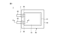
- FIG. 1 is a plan view of a secondary battery according to an embodiment of the present disclosure.
- FIG. 2 is a cross-sectional view of the secondary battery taken along line II-II shown in FIG.
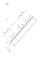
- FIG. 3 is a schematic diagram showing a process of joining a positive electrode terminal and a plurality of current collectors.
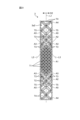
- FIG. 4 is a plan view of the support surface of the anvil.
- FIG. 5 is a view of the anvil as seen from the arrow V shown in FIG.
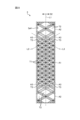
- FIG. 6 is a plan view of the pressing surface of the horn.
- FIG. 7 is a side view of the horn.
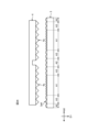
- FIG. 8 is a cross-sectional view of the horn taken along line VIII-VIII shown in FIG. FIG.
- FIG. 9 is a cross-sectional view of the horn taken along line IX-IX shown in FIG.
- FIG. 10 is a diagram showing the amount of wear on the support surface of the anvil according to the embodiment of the present disclosure shown in FIG. 4 and the amount of wear on the support surface of the anvil of the comparative example.
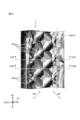
- FIG. 11 is a plan view of the joints between the multiple current collectors and the positive electrode terminal, as viewed from the positive electrode terminal side.
- FIG. 12 is a partial enlarged view of the first concave-convex region showing the first concave-convex pattern shown in FIG.
- FIG. 13 is a cross-sectional view of the joint.
- FIG. 14 is a partial enlarged view of the first concave-convex region showing the first concave-convex pattern, the second concave-convex pattern, and the third concave-convex pattern shown in FIG.
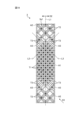
- FIG. 15 is a plan view of the joints between the multiple current collectors and the positive electrode terminal, as viewed from the current collector side.
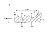
- FIG. 16 is an enlarged view of the second uneven area shown in FIG.
- FIG. 17 is a cross-sectional view of the joint taken along line XVII-XVII shown in FIG.
- FIG. 18 is a cross-sectional view of the joint taken along line XVIII-XVIII shown in FIG. FIG.
- FIG. 19 is a plan view of an anvil used in a joining process according to a first modified example of the embodiment of the present disclosure.
- 20 is a view of the anvil as seen from the arrow XX shown in FIG. 19.
- FIG. 21 is a plan view of an anvil used in a joining process according to a second modified example of the embodiment of the present disclosure.
- FIG. 22 is a plan view of an anvil used in a joining process according to a third modified example of the embodiment of the present disclosure.
- FIG. 23 is a plan view of an anvil used in a joining process according to a fourth modified example of the embodiment of the present disclosure.
- FIG. 24 is a plan view of an anvil used in a joining process according to a fifth modified example of an embodiment of the present disclosure.
- FIG. 25 is a plan view of an anvil used in a joining process according to a sixth modified example of an embodiment of the present disclosure.
- FIG. 26 is a side view of an anvil and a horn according to a sixth variation of an embodiment of the present disclosure.
- FIG. 27 is a plan view of an anvil used in a joining process according to a seventh modified example of the embodiment of the present disclosure.
- FIG. 28 is a plan view of an anvil used in a joining process according to an eighth modified example of the embodiment of the present disclosure.
- FIG. 1 is a plan view of a secondary battery 1 according to an embodiment of the present disclosure.
- FIG. 2 is a cross-sectional view of the secondary battery 1 taken along line II-II shown in FIG. 1.
- the secondary battery 1 is, for example, a lithium ion battery. As shown in FIG. 1, the secondary battery 1 includes a laminate 10, a positive electrode terminal 20, a negative electrode terminal 30, an exterior body 40, and a current collector 50.
- the laminate 10 is housed in an exterior body 40. As shown in FIG. 2, the laminate 10 has a laminated structure and has a plurality of sheet-shaped positive electrodes 11 and negative electrodes 12, with the plurality of positive electrodes 11 and the plurality of negative electrodes 12 stacked alternately with separators 13 between them.
- the positive electrode terminal 20 is a plate having an L-shaped cross section with a bent surface 21, and one end including the bent surface 21 is located inside the exterior body 40. The other end of the positive electrode terminal 20 is located outside the exterior body 40.
- the positive electrode terminal 20 may be a plate that is not bent.
- the positive electrode terminal 20 is electrically connected to each of the multiple positive electrodes 11 via multiple current collectors 50.
- the current collectors 50 are metal foils.
- the positive electrode terminal 20 and the current collectors 50 connected to the positive electrode terminal 20 are made of the same metal (e.g., aluminum).
- the positive electrode terminal 20 and the multiple current collectors 50 are electrically joined to form a joint J (described in detail below).
- the negative electrode terminal 30, like the positive electrode terminal 20, has an L-shaped cross section with a bent surface, and one end including the bent surface is located inside the exterior body 40. The other end of the negative electrode terminal 30 is located outside the exterior body 40.
- the negative electrode terminal 30 is electrically connected to each of the multiple negative electrodes 12 via multiple current collectors 50.
- the negative electrode terminal 30 and the current collectors 50 connected to the negative electrode terminal 30 are each formed of the same metal (e.g., copper).
- the negative electrode terminal 30 and the multiple current collectors 50 are electrically joined to form a joint J (details will be described later).
- the negative electrode terminal 30 and the current collectors 50 connected to the negative electrode terminal 30 may be formed of different metals.
- the material of the negative electrode terminal 30 may be copper
- the material of the current collectors 50 connected to the negative electrode terminal 30 may be nickel, nickel-plated copper, nickel-clad copper, etc.
- the exterior body 40 has a housing portion 41 that houses the laminate 10 and a flange portion 42 around the housing portion 41.
- the housing portion 41 houses an electrolyte (e.g., a nonaqueous electrolyte solution).
- the exterior body 40 is formed by folding back a single film. A portion of the film is formed into a convex shape, for example by press processing, to form the storage section 41. The overlapping portions of the film around the storage section 41 are joined to form the flange section 42, which prevents leakage of the electrolyte.
- Figure 3 is a schematic diagram showing the process of joining the positive electrode terminal 20 and the multiple current collectors 50.
- the positive electrode terminal 20 and the multiple current collectors 50 are joined using an ultrasonic joining machine 2.
- the ultrasonic joining machine 2 is equipped with an anvil 3 having a support surface 3a that supports the workpiece, a horn 4 having a pressing surface 4a that presses the workpiece, and an ultrasonic vibration generator 5 that applies ultrasonic vibrations to the horn 4.
- the horn 4 presses the positive electrode terminal 20 and the multiple current collectors 50 along a pressing direction D1 that runs along the thickness direction of the positive electrode terminal 20.
- the horn 4 also vibrates along a vibration direction D2 that is perpendicular to the pressing direction D1.
- Figure 4 is a plan view of the support surface 3a of the anvil 3.
- Figure 5 is a view of the anvil 3 as seen from the arrow V shown in Figure 4. Arrow V is aligned with a third straight line L3, which will be described later.
- the support surface 3a of the anvil 3 is rectangular in shape extending along a first straight line L1 perpendicular to the vibration direction D2 of the horn 4 in a plan view.
- the plan view of the support surface 3a is when the support surface 3a is viewed along the pressing direction D1.
- a plurality of first protrusions T1, a plurality of second protrusions T2, and a plurality of third protrusions T3 are arranged on the support surface 3a such that the support surface 3a has a line-symmetric shape with respect to the first straight line L1 as the axis of symmetry.
- the first protrusion T1, the second protrusion T2 and the third protrusion T3 are each in the shape of a quadrangular pyramid. In other words, the upper and lower surfaces of the first protrusion T1, the second protrusion T2 and the third protrusion T3 are flat.
- the first protrusion T1, the second protrusion T2 and the third protrusion T3, which overlap with the periphery of the support surface 3a in a planar view, are cut off by the periphery of the support surface 3a in a planar view.
- the shapes of the first protrusion T1, the second protrusion T2 and the third protrusion T3 will be described with reference to the shapes when they are not cut off by the periphery of the support surface 3a2.
- the bottom surfaces of the first protrusions T1, the second protrusions T2, and the third protrusions T3 are located on a first plane S1 that is perpendicular to the pressing direction D1.
- the top surfaces of the first protrusions T1, the second protrusions T2, and the third protrusions T3 are located on a second plane S2 that is parallel to the first plane S1 (i.e., on the same plane). In other words, the heights of the first protrusions T1, the second protrusions T2, and the third protrusions T3 are equal to each other.
- the first range A1 in which the multiple first protrusions T1 are arranged is located in the center of the support surface 3a in the direction along the first straight line L1 in a plan view.
- the lower and upper surfaces of the first protrusions T1 are square-shaped in a plan view.
- the multiple first protrusions T1 are arranged adjacent to each other with their diagonals parallel to the first straight line L1.
- the multiple first protrusions T1 are arranged in a matrix along the second straight line L2 and third straight line L3 that intersect with the first straight line L1 in a plan view.
- the second line L2 and the third line L3 are perpendicular to each other, and the angles that the second line L2 and the third line L3 make with the first line L1 are equal to each other, 45°.
- the edge of the lower surface of the first protrusion T1 is parallel to one of the second line L2 and the third line L3.
- edges of the lower surfaces of two adjacent first protrusions T1 are in contact with each other.
- the cross section between two adjacent first protrusions T1 is V-shaped.
- the second range A2 in which the multiple second protrusions T2 are arranged is arranged adjacent to the first range A1 on both outer sides of the first range A1 in the direction along the first straight line L1.
- the second range A2 is located outside the ranges extending from the first range A1 along the second straight line L2 and the third straight line L3.
- the bottom and top surfaces of the second protrusion T2 are square in plan view.
- the length of the sides on the bottom surface of the second protrusion T2 is longer than the length of the sides on the bottom surface of the first protrusion T1 (specifically, twice as long).
- the area of the bottom surface of the second protrusion T2 is larger than the area of the bottom surface of the first protrusion T1 (specifically, four times as long).
- the area of the top surface of the second protrusion T2 is larger than the area of the top surface of the first protrusion T1.
- the multiple second protrusions T2 are arranged adjacent to one another with the diagonal of the lower surface parallel to the first straight line L1. As a result, the multiple second protrusions T2 are positioned in a matrix along the second straight line L2 and the third straight line L3 in a plan view. The side of the lower surface of the second protrusions T2 is parallel to one of the second straight line L2 and the third straight line L3.
- the edges of the lower surfaces of two adjacent second protrusions T2 are in contact with each other.
- the cross section between two adjacent second protrusions T2 is V-shaped.
- the vertices of the lower surfaces of the adjacent second protrusions T2 and first protrusions T1 are in contact with each other.
- the cross section between the adjacent second protrusions T2 and first protrusions T1 is V-shaped.
- the third range A3 in which the multiple third protrusions T3 are arranged is located in a range extending from the first range A1 along each of the second straight line L2 and the third straight line L3.
- the multiple third ranges A3 are between the first range A1 and the second range A2 in the direction along the first straight line L1.
- the third range A3 is adjacent to the first range A1 in the direction along one of the second straight line L2 and the third straight line L3.
- the multiple third ranges A3 are also adjacent to the second range A2 in the direction along one of the second straight line L2 and the third straight line L3.
- the lower and upper surfaces of the third protrusion T3 are rectangular in plan view. In plan view, the area of the upper surface of the third protrusion T3 is larger than the area of the upper surface of the first protrusion T1 and smaller than the area of the upper surface of the second protrusion T2.
- the length of the long side and the short side of the underside of the third protrusion T3 are equal to the length of one side of the underside of the second protrusion T2, and the length of the short side is equal to the length of one side of the underside of the first protrusion T1.
- the multiple third protrusions T3 are arranged in a matrix along the second straight line L2 and the third straight line L3 in a plan view.
- the side of the underside of the third protrusion T3 is parallel to one of the second straight line L2 and the third straight line L3.
- edges of the lower surfaces of two adjacent third protrusions T3 are in contact with each other.
- the cross section between two adjacent third protrusions T3 is V-shaped.
- the adjacent third protrusion T3 and first protrusion T1 are adjacent to each other in a direction along one of the second straight line L2 and the third straight line L3, and the edges of the lower surfaces of the adjacent third protrusion T3 and first protrusion T1 are in contact with each other.
- the cross section between the adjacent third protrusion T3 and first protrusion T1 is V-shaped.
- the adjacent third protrusion T3 and second protrusion T2 are adjacent to each other in a direction along one of the second straight line L2 and the third straight line L3, and the edges of the lower surfaces of the adjacent third protrusion T3 and second protrusion T2 are in contact with each other.
- the cross section between the adjacent third protrusion T3 and second protrusion T2 is V-shaped.
- the inclination angles of the side surfaces of the first protrusion T1, the second protrusion T2, and the third protrusion T3 are equal to each other.
- the manufacturing process can be simplified. Specifically, the multiple grooves with a V-shaped cross section that are located between the first protrusion T1, the second protrusion T2, and the third protrusion T3 and are formed by the side surfaces of the first protrusion T1, the second protrusion T2, and the third protrusion T3 continue from one side of the support surface 3a to the other side in a direction along one of the second straight line L2 and the third straight line L3.
- the above-mentioned multiple first protrusions T1, multiple second protrusions T2, and multiple third protrusions T3 can be easily formed by moving a grindstone having a V-shaped cross section corner from one side of the support surface 3a to the other side in a direction along the second straight line L2 and the third straight line L3 to grind the support surface 3a.
- FIG. 6 is a plan view of the pressing surface 4a of the horn 4.
- FIG. 7 is a side view of the horn 4.
- FIG. 8 is a cross-sectional view of the horn 4 taken along line VIII-VIII shown in FIG. 6.
- FIG. 9 is a cross-sectional view of the horn 4 taken along line IX-IX shown in FIG. 6.
- the pressing surface 4a of the horn 4 is rectangular in plan view, extending along a fourth straight line L4 perpendicular to the vibration direction D2. Note that the plan view of the pressing surface 4a is the pressing surface 4a viewed along the pressing direction D1. In plan view, the corners of the pressing surface 4a are chamfered. In plan view, the area of the pressing surface 4a is smaller than the area of the support surface 3a.
- a number of sixth protrusions T6 are arranged on the pressing surface 4a, with the pressing surface 4a being linearly symmetrical with respect to the fourth straight line L4 as the axis of symmetry.
- the sixth protrusions T6 are arranged in a matrix along the fifth straight line L5 and the sixth straight line L6 that intersect with the fourth straight line L4 in a plan view.
- the fifth line L5 and the sixth line L6 are perpendicular to each other, and the angles that the fifth line L5 and the sixth line L6 make with the fourth line L4 are equal to each other, 45°.
- the edge of the lower surface of the sixth protrusion T6 is parallel to one of the fifth line L5 and the sixth line L6.
- the sixth protrusion T6 has a square-shaped underside, with a width that narrows toward the protruding end.
- the underside edges of two adjacent sixth protrusions T6 are in contact with each other.
- the undersides of the multiple sixth protrusions T6 are located on a third plane S3 that is perpendicular to the pressing direction D1.
- the sixth protrusions T6 are arranged such that the diagonal of the lower surface is parallel to the fourth straight line L4 in a plan view.
- the sixth protrusion T6 whose upper surface overlaps with the fourth straight line L4 in a plan view will be referred to as the seventh protrusion T7
- the sixth protrusions T6 on both sides of the seventh protrusion T7 in the vibration direction D2 will be referred to as the eighth protrusion T8.
- the pressing surface 4a has an arc C that passes through the periphery of the pressing surface 4a in the vibration direction D2 and is convex toward the outside of the horn 4 in a side view perpendicular to the vibration direction D2.
- the seventh protrusion T7 does not overlap with the arc C in a side view.
- the seventh protrusion T7 is a truncated cone with quadrangular (specifically, square) upper and lower surfaces. As shown in Figures 7 and 8, the upper and side surfaces of the seventh protrusion T7 are linear in a cross-sectional view.
- the eighth protrusion T8 has an arc shape that follows arc C in side view. That is, as shown in Figures 8 and 9, the top and side surfaces of the eighth protrusion T8 have a shape that follows arc C in cross section. Specifically, the eighth protrusion T8 has the same truncated cone shape as the seventh protrusion T7, with the top side cut away by a curved surface that forms arc C in side view. As a result, the heights H2a and H2b of the eighth protrusion T8 are lower than the height H1 of the seventh protrusion T7.
- the eighth protrusion T8 shown in FIG. 8 is closer to the periphery of the pressing surface 4a in the vibration direction D2 than the eighth protrusion T8 shown in FIG. 9, and the height H2b of the eighth protrusion T8 shown in FIG. 8 is lower than the height H2a of the eighth protrusion T8 shown in FIG. 9.
- the height H1 of the seventh protrusion T7 is higher than the heights of the first protrusion T1, the second protrusion T2 and the third protrusion T3 of the anvil 3 (i.e., the distance between the first plane S1 and the second plane S2).
- the joining process the process of joining the positive electrode terminal 20 and the multiple current collectors 50 (hereinafter referred to as the joining process) will be described.
- the positive electrode terminal 20 is placed in a state where the surface opposite the folded surface 21 of the positive electrode terminal 20 is in contact with the support surface 3a of the anvil 3.
- multiple current collectors 50 are placed in a stacked state on the folded surface 21 of the positive electrode terminal 20.
- the support surface 3a and the pressing surface 4a face each other in an overlapping state.
- the first range A1, the second range A2, and the third range A3 of the support surface 3a each overlap the multiple sixth protrusions T6 of the pressing surface 4a.
- the multiple current collectors 50 are pressed along the pressing direction D1 by the pressing surface 4a of the horn 4, and the horn 4 vibrates along the vibration direction D2, so that the positive electrode terminal 20 and the multiple current collectors 50 are welded together and integrated to form a joint J.
- the negative electrode terminal 30 and the multiple current collectors 50 are also similarly joined using the ultrasonic joining machine 2 to form a joint J.
- the horn 4 extends along the fourth straight line L4 that is perpendicular to the vibration direction D2.
- the vibration of the horn 4 during the joining process occurs not only along the vibration direction D2 but also along the pressing direction D1. Therefore, on the support surface 3a of the anvil 3, the load acting on the support surface 3a during the joining process is greater on both sides of the support surface 3a in the direction along the first straight line L1 than on the central portion of the support surface 3a in the direction along the first straight line L1 that is perpendicular to the vibration direction D2, which may result in greater wear of the support surface 3a.
- multiple first protrusions T1 are located in the center of the support surface 3a in the direction along the first straight line L1
- multiple second protrusions T2 are located at both ends of the support surface 3a in the direction along the first straight line L1.
- the area of the upper surface of the second protrusions T2 is larger than the area of the upper surface of the first protrusions T1. Therefore, the load acting on the support surface 3a during the joining process is prevented from concentrating at both ends of the support surface 3a in the direction along the first straight line L1, and wear on the support surface 3a can be suppressed.
- the heights of the multiple first protrusions T1, the multiple second protrusions T2, and the multiple third protrusions T3 are equal to each other. This makes it possible to prevent the load acting on the multiple first protrusions T1, the multiple second protrusions T2, and the multiple third protrusions T3 from concentrating. This makes it possible to equalize the amount of wear of the multiple first protrusions T1, the multiple second protrusions T2, and the multiple third protrusions T3.
- Figure 10 is a diagram showing the amount of wear on the support surface 3a of the anvil 3 according to the embodiment of the present disclosure shown in Figure 4 and the amount of wear on the support surface of the anvil 6 of the comparative example.
- the vertical axis of Figure 10 shows the average amount of wear on each of the protrusions T1, T2, and T3, and the horizontal axis of Figure 10 shows the number of times the current collector 50 and the positive electrode terminal 20 are joined (the number of shots, so to speak).
- the anvil 6 of the comparative example differs from the anvil 3 of the above embodiment in that the entire support surface is formed by the first protrusion T1.
- the first protrusion T1 is disposed over the entire support surface of the anvil 6 of the comparative example.
- the average wear amount of the support surface 3a in the anvil 3 of this embodiment is less than the average wear amount of the support surface in the anvil 6 of the comparative example. Furthermore, the greater the number of joining times, the greater the difference between the average wear amount of the support surface 3a in the anvil 3 of this embodiment and the average wear amount of the support surface in the anvil 6 of the comparative example. In other words, FIG.
- FIG. 11 is a plan view of joint J between multiple current collectors 50 and the positive electrode terminal 20, as viewed from the positive electrode terminal 20 side.
- the plan view of joint J shown in FIG. 11 is a diagram showing a plan view of joint J as viewed from the positive electrode terminal 20 side along the thickness direction of the positive electrode terminal 20.
- the plan view of joint J means that joint J is viewed along the thickness direction of the positive electrode terminal 20.
- the outer surface of the positive electrode terminal 20 at the joint J has a first uneven region R1 with multiple depressions that are recessed in the thickness direction of the positive electrode terminal 20.
- the two-dot chain line in FIG. 11 indicates the periphery of the first uneven region R1.
- the first uneven region R1 is formed by pressing the current collector 50 along the pressing direction D1 with the horn 4 while the positive electrode terminal 20 is supported on the support surface 3a of the anvil 3.
- the first uneven region R1 extends along the first direction W1.
- the first direction W1 is approximately perpendicular to the pressing direction D1 and the vibration direction D2.
- the first uneven region R1 has a first uneven pattern P1, two second uneven patterns P2, and four third uneven patterns P3.
- the seventh line L7, eighth line L8, ninth line L9, and tenth line L10 shown in FIG. 11 indicate the boundary lines between the first uneven pattern P1, the second uneven pattern P2, and the third uneven pattern P3 (details will be described later).
- the first uneven pattern P1 is located in the center of the first uneven region R1 in the first direction W1.
- the first uneven pattern P1 is between two second uneven patterns P2 in a plan view. Specifically, the first uneven pattern P1 is between two second uneven patterns P2 in the first direction W1.
- the first uneven pattern P1 has a plurality of first recesses U1.
- first recess U1 as well as the second recess U2 and third recess U3 described below, which overlap with the periphery of the first uneven region R1 in a planar view, have shapes that are cut off by the periphery of the first uneven region R1 in a planar view.
- the shapes of the first recess U1, second recess U2 and third recess U3 will be described in terms of the shapes when they are not cut off by the periphery of the first uneven region R1.
- the multiple first recesses U1 are arranged in a matrix along the second direction W2 and the third direction W3 that intersect with each other in a planar view.
- the second direction W2 and the third direction W3 are perpendicular to each other in a planar view.
- the second direction W2 and the third direction W3 each intersect with the first direction W1.
- FIG. 12 is a partial enlarged view of the first uneven region R1 showing the first uneven pattern P1 shown in FIG. 11.
- FIG. 12 is an enlarged view of the range shown in the rectangular frame XI shown in FIG. 11.
- the bottom B1 of the first recess U1 corresponds to the shape of the upper surface of the first protrusion T1 of the support surface 3a.
- the bottom B1 of the first recess U1 is planar and has a square shape in a plan view.
- planar refers to a range having a predetermined surface roughness or less that is sufficiently smaller than the step between the periphery of the bottom B1 of the first recess U1 in the pressing direction D1 and the bottom B1.
- the sufficiently small predetermined surface roughness is 1/10 or less of the step between the periphery of the bottom B1 of the first recess U1 in the pressing direction D1 and the bottom B1.
- the surface roughness can be measured by measuring and analyzing the three-dimensional shape of the surface of the bottom B1 using a non-contact surface roughness measuring device such as a laser microscope.
- the non-contact surface roughness measuring instrument is set to a magnification of 200 times, and a measurement range of 0.05 mm in diameter is set near the center of the bottom B1 of the first recess D1 to obtain the surface roughness. For example, when the measured roughness Ry ( ⁇ m) is 20 ( ⁇ m) or less, the bottom B1 can be determined to be flat.
- the roughness Ry is the maximum height specified in JIS B 0601 (1994) and JIS B 0031 (1994).
- the intervals between the bottoms B1 of two adjacent first recesses U1 are equal to each other.
- FIG. 13 is a cross-sectional view of joint J.
- the upper surfaces of the multiple first protrusions T1 are located on the same plane, so that the bottoms B1 of the multiple first recesses U1 are located on the fourth plane S4 (i.e., on the same plane).
- the second uneven pattern P2 is located adjacent to the first uneven pattern P1 on both outer sides of the first uneven pattern P1 in the first direction W1.
- the second uneven pattern P2 is located outside the range extending from the first uneven pattern P1 along the second direction W2 and the third direction W3 in a plan view.
- the second uneven pattern P2 has a plurality of second recesses U2.
- the second recesses U2 are aligned along one of the second direction W2 and the third direction W3 in a plan view.
- the second recesses U2 are aligned in a matrix along the second direction W2 and the third direction W3 in a plan view.
- the area of the second recesses U2 is larger than the area of the first recesses U1.
- FIG. 14 is a partial enlarged view of the first uneven region R1 showing the first uneven pattern P1, the second uneven pattern P2, and the third uneven pattern P3 shown in FIG. 11.
- FIG. 14 is an enlarged view of the range shown in the rectangular frame XIV shown in FIG. 11.
- the bottom B2 of the second recess U2 corresponds to the shape of the upper surface of the second protrusion T2 of the support surface 3a.
- the bottom B2 of the second recess U2 is flat and square in plan view.
- the area of the bottom B2 of the second recess U2 is greater than the area of the bottom B1 of the first recess U1.
- the length of the bottom B2 of the second recess U2 is greater than the length of the bottom B1 of the first recess U1.
- the distance between the bottoms B2 of two adjacent second recesses U2 (specifically, the distance between the center points of the bottoms B2 of the second recesses U2 in a plan view) is equal to each other. Furthermore, in each of the second direction W2 and the third direction W3, the distance between the bottoms B2 of two adjacent second recesses U2 is greater than the distance between the bottoms B1 of two adjacent first recesses U1.
- the bottoms B2 of the second recesses U2 are located on the fourth plane S4 (i.e., on the same plane).
- the upper surfaces of the first protrusions T1 and the upper surfaces of the second protrusions T2 are located on the same plane, so that the bottoms B1 of the first recesses U1 and the bottoms B2 of the second recesses U2 are located on the same plane.
- the third uneven pattern P3 is located in a range extending from the first uneven pattern P1 along both the second direction W2 and the third direction W3.
- the third uneven pattern P3 is between the first uneven pattern P1 and the second uneven pattern P2 in the first direction W1.
- the third uneven pattern P3 is adjacent to the first uneven pattern P1 in either the second direction W2 or the third direction W3.
- the third uneven pattern P3 is also adjacent to the second uneven pattern P2 in either the second direction W2 or the third direction W3.
- the third uneven pattern P3 has a plurality of third recesses U3.
- the multiple third recesses U3 are aligned along at least one of the second direction W2 and the third direction W3 in a plan view.
- the area of the third recesses U3 is larger than the area of the first recesses U1 and smaller than the area of the second recesses U2.
- the bottom B3 of the third recess U3 shown in FIG. 14 corresponds to the shape of the upper surface of the third protrusion T3 of the support surface 3a. Specifically, the bottom B3 of the third recess U3 is flat and rectangular in plan view. The area of the bottom B3 of the third recess U3 is larger than the area of the bottom B1 of the first recess U1 and smaller than the area of the bottom B2 of the second recess U2.
- the distance between the bottoms B3 of two adjacent third recesses U3 in the second direction W2 (specifically, the distance between the center points of the bottoms B3 of the third recesses U3 in a plan view) is different from the distance between the bottoms B3 of two adjacent third recesses U3 in the third direction W3.
- the distance between the bottoms B3 of two third recesses U3 adjacent to each other in the second direction W2 is equal to the distance between the bottoms B2 of two second recesses U2 adjacent to each other in the second direction W2 and the third direction W3
- the distance between the bottoms B3 of two third recesses U3 adjacent to each other in the third direction W3 is equal to the distance between the bottoms B1 of two first recesses U1 adjacent to each other in the second direction W2 and the third direction W3.
- the distance between the bottoms B3 of two third recesses U3 adjacent to each other in the second direction W2 is equal to the distance between the bottoms B1 of two first recesses U1 adjacent to each other in the second direction W2 and the third direction W3
- the distance between the bottoms B3 of two third recesses U3 adjacent to each other in the third direction W3 is equal to the distance between the bottoms B1 of two first recesses U1 adjacent to each other in the second direction W2 and the third direction W3.
- the bottoms B3 of the multiple third recesses U3 are located on the fourth plane S4 (i.e., on the same plane), as are the bottoms B1 of the multiple first recesses U1 and the bottoms B2 of the multiple second recesses U2.
- the top surfaces of the multiple first protrusions T1, the top surfaces of the multiple second protrusions T2, and the top surfaces of the multiple third protrusions T3 are located on the same plane, so that the bottoms B1 of the multiple first recesses U1, the bottoms B2 of the multiple second recesses U2, and the bottoms B3 of the multiple third recesses U3 are located on the same plane.
- the seventh line L7 and the ninth line L9 are parallel to the second direction W2.
- the seventh line L7 and the ninth line L9 pass between the first recess U1 and the third recess U3, and between the third recess U3 and the second recess U2, which are adjacent to each other in the third direction W3.
- the eighth line L8 and the tenth line L10 are parallel to the third direction W3.
- the eighth line L8 and the tenth line L10 pass between the first recess U1 and the third recess U3, and between the third recess U3 and the second recess U2, which are adjacent to each other in the second direction W2.
- the seventh line L7, the eighth line L8, the ninth line L9, and the tenth line L10 correspond to the ridges between the first concave-convex pattern P1, the second concave-convex pattern P2, and the third concave-convex pattern P3, which are adjacent to each other.
- the ranges of the first uneven pattern P1, the second uneven pattern P2, and the third uneven pattern P3 can be determined by drawing the periphery of the first uneven region R1, the seventh straight line L7, the eighth straight line L8, the ninth straight line L9, and the tenth straight line L10 on an image of the outer surface of the joint J magnified, for example, by 100 times.
- the distance between the center points of the bottoms B1 of the first recesses U1, the distance between the center points of the bottoms B2 of the second recesses U2, the distance between the center points of the bottoms B3 of the third recesses U3, the area of the first recesses U1, the area of the second recesses U2, the area of the third recesses U3, the area of the bottoms B1 of the first recesses U1, the area of the bottoms B2 of the second recesses U2, and the area of the bottoms B3 of the third recesses U3 can also be measured using an image of the outer surface of the joint J magnified, for example, by 100 times.
- the vibration of the horn 4 in the joining process occurs not only along the vibration direction D2 but also along the pressing direction D1. Therefore, the load acting on the first uneven region R1 in the joining process is greater on both sides of the first uneven region R1 in the first direction W1 than in the center of the first uneven region R1 in the first direction W1, which may cause cracks to occur in the joint J.
- first recesses U1 are located in the center of the first uneven region R1 in the first direction W1
- multiple second recesses U2 are located at both ends of the first uneven region R1 in the first direction W1.
- the area of the second recesses U2 is larger than the area of the first recesses U1. This prevents the load acting on the joint J during the joining process from concentrating at both ends of the first uneven region R1 in the first direction W1.
- the area of the second recesses U2 is larger than the area of the first recesses U1, thereby preventing local compression of the joint J at both ends of the first uneven region R1. This prevents cracks from occurring at the joint J, and stabilizes the bond between the multiple current collectors 50 and the positive electrode terminal 20 at the joint J.
- the bottoms B1 of the first recesses U1, the bottoms B2 of the second recesses U2, and the bottoms B3 of the third recesses U3 are located on the same plane. Therefore, local compression of the joint J is suppressed compared to when the bottoms B1 of the first recesses U1, the bottoms B2 of the second recesses U2, and the bottoms B3 of the third recesses U3 are located on different planes. Therefore, it is possible to suppress the occurrence of cracks in the joint J, and it is possible to stabilize the bonded state between the multiple current collectors 50 and the positive electrode terminal 20 at the joint J.
- FIG. 15 is a plan view of the joint J between the multiple current collectors 50 and the positive electrode terminal 20, as viewed from the current collector 50 side.
- the plan view of the joint J shown in FIG. 15 is a diagram showing a plan view of the joint J as viewed from the current collector 50 side along the thickness direction of the positive electrode terminal 20.
- the outer surface of the current collector 50 at the joint J has a second uneven region R2 with multiple recesses that are recessed in the thickness direction of the positive terminal 20.
- the second uneven region R2 is formed by pressing the current collector 50 along the pressing direction D1 with the horn 4 while the positive terminal 20 is supported on the support surface 3a of the anvil 3.
- the second uneven region R2 extends along the first direction W1.
- the second uneven region R2 has multiple sixth recesses U6.
- FIG. 16 is an enlarged view of the second uneven region R2 shown in FIG. 15.
- FIG. 17 is a cross-sectional view of joint J taken along line XVII-XVII shown in FIG. 16.
- FIG. 18 is a cross-sectional view of joint J taken along line XVIII-XVIII shown in FIG. 16.
- the sixth recesses U6 correspond to the shape of the sixth protrusion T6 (seventh protrusion T7 and eighth protrusion T8: see Figures 7, 8 and 9) of the pressing surface 4a.
- the sixth recess U6 located in the center of the second uneven region R2 in the vibration direction D2 corresponds to the shape of the seventh protrusion T7 of the horn 4.
- the sixth recesses U6 located on both sides of the second uneven region R2 in the vibration direction D2 correspond to the shape of the eighth protrusion T8.
- the sixth recesses U6 are arranged in a matrix along the second direction W2 and the third direction W3.
- the height of the eighth protrusion T8 of the horn 4 is lower than the height of the seventh protrusion T7.
- the depth of the sixth recess U6 becomes shallower as it approaches the periphery of the second uneven region R2 in the vibration direction D2. Therefore, as shown in Figures 17 and 18, when the seventh straight line L7 connecting the periphery E of the second uneven region R2 on both sides in the vibration direction D2 is used as a reference, the depth of the bottom B6a of the sixth recess U6 located in the center of the vibration direction D2 is the deepest among the multiple sixth recesses U6. And, the depth of the bottom of the sixth recess U6 becomes shallower as it approaches the periphery E of the second uneven region R2 in the vibration direction D2.
- the bottom B6a of the sixth recess U6 located in the center of the vibration direction D2 shown in Figure 17 the bottom B6b of the sixth recess U6 located outside the center in the vibration direction D2 shown in Figure 18, and the bottom B6c of the sixth recess U6 located outside the center in the vibration direction D2 shown in Figure 17 are closer to the periphery E of the second uneven region R2 in the vibration direction D2, in that order.
- the depths of the bottom B6a, the bottom B6b, and the bottom B6c are shallower in that order.
- the compression ratio of the joint J at the bottom of the sixth recess U6 decreases as it approaches the periphery E of the second uneven region R2.
- damage to the current collector 50 at the periphery of the second uneven region R2 in the vibration direction D2 is suppressed. Therefore, the joining state between the multiple current collectors 50 and the positive electrode terminal 20 can be stabilized.
- the eighth protrusion T8 of the horn 4 is arc-shaped along the arc C that passes through the periphery of the pressing surface 4a in the vibration direction D2 in a cross-sectional view. Therefore, as shown in Figures 17 and 18, in the sixth recess U6 that is located outside the center in the vibration direction D2 and overlaps with the periphery E of the second uneven region R2, the outer surface connecting the periphery E of the second uneven region R2 to the bottom is arc-shaped in cross section that roughly follows the arc C.
- the compression ratio of the joint J decreases from the bottom toward the periphery E of the second uneven region R2.
- damage to the current collector 50 at the periphery of the second uneven region R2 in the vibration direction D2 is suppressed. Therefore, the joining state between the multiple current collectors 50 and the positive electrode terminal 20 can be stabilized.
- the seventh protrusion T7 of the horn 4 has a flat upper surface. Therefore, the bottom B6a of the sixth recess U6 located in the center of the vibration direction D2 shown in FIG. 16 is flat.
- the current collector 50 is compressed into a flat shape, which prevents damage to the current collector 50. Therefore, the joint state between the multiple current collectors 50 and the positive electrode terminal 20 can be stabilized.
- the height H1 of the seventh protrusion T7 corresponding to the second uneven region R2 is higher than the heights of the first protrusion T1, the second protrusion T2, and the third protrusion T3 corresponding to the first uneven region R1.
- the depth De1 corresponding to the depth of the first recess U1, the depth of the second recess U2, and the depth of the third recess U3 of the first uneven region R1 is shallower than the depth De2 corresponding to the depth of the deepest portion (i.e., the bottom B6a) of the sixth recess U6 of the second uneven region R2.
- the depth of the first uneven region R1 is shallower than the depth of the second uneven region R2.
- the compression ratio of the joint J on the positive electrode terminal 20 side is lower than the compression ratio of the joint J on the current collector 50 side. Therefore, it is possible to suppress the occurrence of cracks in the joint J on the positive electrode terminal 20 side, and to stabilize the joint state between the multiple current collectors 50 and the positive electrode terminal 20 at the joint J.
- the joining of the multiple current collectors 50 to the negative electrode terminal 30 is performed in the same manner as the joining of the multiple current collectors 50 to the positive electrode terminal 20. That is, the joint J between the multiple current collectors 50 and the negative electrode terminal 30 has a first uneven region R1 and a second uneven region R2 formed therein, similar to the joint J between the multiple current collectors 50 and the positive electrode terminal 20. Therefore, the joint J between the multiple current collectors 50 and the negative electrode terminal 30 can stabilize the joining state between the multiple current collectors 50 and the negative electrode terminal 30, similar to the joint J between the multiple current collectors 50 and the positive electrode terminal 20 described above.
- FIG. 19 is a plan view of the anvil 3 used in the joining process according to the first modified embodiment of the present disclosure.
- FIG. 20 is an arrow view of the anvil 3 as viewed from the arrow XX shown in FIG. 19. The arrow XX is aligned along the third direction W3.
- the multiple first protrusions T1 are pyramidal.
- the multiple third protrusions T3 are triangular in cross section with a square bottom surface.
- the multiple second protrusions T2 are pyramidal truncated in the same way as the second protrusions T2 in the above embodiment.
- the bottom B1 of the first recess U1, the bottom B2 of the second recess U2, and the bottom B3 of the third recess U3 of the first uneven region R1 of the joint J have the following shapes. That is, the bottom B1 of the first recess U1 corresponding to the shape of the first protrusion T1 has a V-shaped cross section. The bottom B3 of the third recess U3 corresponding to the shape of the third protrusion T3 has a V-shaped cross section.
- the bottom B2 of the second recess U2 corresponding to the shape of the second protrusion T2 is planar like the bottom B2 of the second recess U2 in the above embodiment, and is square in plan view.
- Figure 21 is a plan view of the anvil 3 used in the joining process according to the second modified embodiment of the present disclosure.
- the support surface 3a2 of the anvil 3 further includes a plurality of fourth protrusions T4 and a plurality of fifth protrusions T5 in addition to a plurality of first protrusions T1, a plurality of second protrusions T2, and a plurality of third protrusions T3.
- the fourth protrusions T4 and the fifth protrusions T5 which overlap with the periphery of the support surface 3a2 in a plan view, have a shape cut off by the periphery of the support surface 3a2 in a plan view.
- the shapes of the fourth protrusions T4 and the fifth protrusions T5 will be described in terms of the shapes when they are not cut off by the periphery of the support surface 3a2.
- the fourth range A4 in which the multiple fourth protrusions T4 are arranged is arranged adjacent to the second range A2 on both outer sides of the two second ranges A2 in the direction along the first straight line L1.
- the fourth range A4 is also located at a position deviated from the direction extending from the second range A2 along each of the second straight line L2 and the third straight line L3.
- the multiple fourth protrusions T4 are in the shape of a quadrangular pyramid. That is, the upper and lower surfaces of the fourth protrusions T4 are flat.
- the lower and upper surfaces of the multiple fourth protrusions T4 are in the shape of a square in a planar view.
- the length of the side on the lower surface of the fourth protrusion T4 is longer than the length of the side on the lower surface of the second protrusion T2 (specifically, twice as long).
- the area of the lower surface of the fourth protrusion T4 is larger than the area of the lower surface of the second protrusion T2 (specifically, four times as long).
- the area of the upper surface of the fourth protrusion T4 is larger than the area of the upper surface of the second protrusion T2.
- the multiple fourth protrusions T4 are arranged adjacent to one another with the diagonal of the lower surface parallel to the first straight line L1. As a result, the multiple fourth protrusions T4 are positioned in a matrix along the second straight line L2 and the third straight line L3 in a plan view. The sides of the lower surfaces of the multiple fourth protrusions T4 are parallel to one of the second straight line L2 and the third straight line L3.
- the edges of the lower surfaces of two adjacent fourth protrusions T4 are in contact with each other.
- the cross section between two adjacent second protrusions T2 is V-shaped.
- the vertices of the lower surfaces of the adjacent fourth protrusions T4 and second protrusions T2 are in contact with each other.
- the cross section between the adjacent fourth protrusions T4 and second protrusions T2 is V-shaped.
- the fifth range A5 in which the multiple fifth protrusions T5 are arranged is adjacent to the second range A2 in the direction along the second straight line L2 and the third straight line L3.
- the fifth range A5 is adjacent to the fourth range A4 in the direction along the second straight line L2 and the third straight line L3.
- the multiple fifth protrusions T5 have a triangular cross section with a square bottom surface.
- the bottom and top surfaces of the fifth protrusions T5 are rectangular in plan view.
- the area of the top surface of the fifth protrusions T5 is larger than the area of the top surface of the second protrusions T2 and smaller than the area of the top surface of the fourth protrusions T4.
- the length of the long side and the short side of the underside of the fifth protrusion T5 is equal to the length of one side of the underside of the fourth protrusion T4, and the length of the short side is equal to the length of one side of the underside of the second protrusion T2.
- the multiple fifth protrusions T5 are arranged along one of the second straight line L2 and the third straight line L3 in a plan view.
- the side of the underside of the multiple third protrusions T3 is parallel to one of the second straight line L2 and the third straight line L3.
- the multiple fifth protrusions T5 may be arranged in a matrix along the second straight line L2 and the third straight line L3 in a plan view.
- edges of the lower surfaces of two adjacent fifth protrusions T5 are in contact with each other.
- the cross section between two adjacent fifth protrusions T5 is V-shaped.
- the adjacent fifth protrusions T5 and fifth protrusions T5 are adjacent to each other in a direction along one of the second straight line L2 and the third straight line L3, and the edges of the lower surfaces of the adjacent fifth protrusions T5 and fifth protrusions T5 are in contact with each other.
- the cross section between the adjacent fifth protrusions T5 and fifth protrusions T5 is V-shaped.
- the adjacent fifth protrusion T5 and fourth protrusion T4 are adjacent to each other in a direction along one of the second straight line L2 and the third straight line L3, and the edges of the lower surfaces of the adjacent fifth protrusion T5 and fourth protrusion T4 are in contact with each other.
- the cross section between the adjacent fifth protrusion T5 and fourth protrusion T4 is V-shaped.
- the inclination angles of the side surfaces of the first protrusion T1, the second protrusion T2, the third protrusion T3, the fourth protrusion T4, and the fifth protrusion T5 are equal to each other. Therefore, the manufacturing process of the support surface 3a2 having such a shape can be simplified. Specifically, the V-shaped cross-sectional grooves between the first protrusion T1, the second protrusion T2, the third protrusion T3, the fourth protrusion T4, and the fifth protrusion T5 continue from one side to the other side of the support surface 3a2 in the direction along the second straight line L2 and the third straight line L3.
- the first uneven region R1 of the joint J in this second modified example further has two fourth uneven patterns (not shown) and four fifth uneven patterns (not shown) in addition to the first uneven pattern P1, the second uneven pattern P2, and the third uneven pattern P3 described above.
- the fourth uneven pattern is located adjacent to the first uneven pattern P1 on both outsides of the two second uneven patterns P2 in the first direction W1.
- the two second uneven patterns P2 are between the two fourth uneven patterns in the first direction W1.
- the fourth uneven pattern is located outside the range extending from the second uneven pattern P2 along the second direction W2 and the third direction W3 in a plan view.
- the fourth uneven pattern has a plurality of fourth recesses (not shown).
- the multiple fourth recesses are aligned along one of the second direction W2 and the third direction W3 in a plan view.
- the multiple fourth recesses may be aligned in a matrix along the second direction W2 and the third direction W3 in a plan view. In a plan view, the area of the fourth recess is greater than the area of the second recess U2.
- the bottom of the fourth recess corresponds to the shape of the upper surface of the fourth protrusion T4 of the support surface 3a2. Specifically, the bottom of the fourth recess is flat and has a square shape in a plan view. The area of the bottom of the fourth recess is greater than the area of the bottom of the fourth recess.
- the distance between the bottoms of two adjacent fourth recesses (specifically, the distance between the center points of the bottoms of the fourth recesses in a plan view) is equal to each other. Furthermore, in each of the second direction W2 and the third direction W3, the distance between the bottoms of two adjacent fourth recesses is greater than the distance between the bottoms B2 of two adjacent second recesses U2.
- the bottoms of the multiple fourth recesses are located on a fourth plane S4 (see FIG. 13). Therefore, the bottoms B1 of the multiple first recesses U1, the bottoms B2 of the multiple second recesses U2, the bottoms B3 of the multiple third recesses U3, and the bottoms of the multiple fourth recesses are located on the same plane.
- the fifth uneven pattern is located in a range extending from the second uneven pattern P2 along both the second direction W2 and the third direction W3.
- the fifth uneven pattern is between the second uneven pattern P2 and the fourth uneven pattern in the first direction W1.
- the fifth uneven pattern is adjacent to the second uneven pattern P2 in either the second direction W2 or the third direction W3.
- the fifth uneven pattern is adjacent to the fourth uneven pattern in either the second direction W2 or the third direction W3.
- the fifth uneven pattern has a plurality of fifth recesses (not shown).
- the multiple fifth recesses are aligned along at least one of the second direction W2 and the third direction W3 in a plan view.
- the area of the fifth recess is larger than the area of the second recess U2 and smaller than the area of the fourth recess.
- the bottom of the fifth recess corresponds to the shape of the upper surface of the fifth protrusion T5 of the support surface 3a. Specifically, the bottom of the fifth recess is flat and rectangular in plan view. The area of the bottom of the fifth recess is greater than the area of the bottom B2 of the second recess U2 and smaller than the area of the bottom of the fourth recess.
- the distance between the bottoms of two adjacent fifth recesses in the second direction W2 (specifically, the distance between the center points of the bottoms of the fifth recesses in a plan view) is different from the distance between the bottoms of two adjacent fifth recesses in the third direction W3.
- the distance between the bottoms of the two fifth recesses adjacent to each other in the second direction W2 is equal to the distance between the bottoms of the two fourth recesses adjacent to each other in the second direction W2 and the third direction W3
- the distance between the bottoms of the two fifth recesses adjacent to each other in the third direction W3 is equal to the distance between the bottoms B2 of the two second recesses U2 adjacent to each other in the second direction W2 and the third direction W3.
- the distance between the bottoms of the two fifth recesses adjacent to each other in the third direction W3 is equal to the distance between the bottoms of the two fourth recesses adjacent to each other in the second direction W2 and the third direction W3
- the distance between the bottoms of the two fifth recesses adjacent to each other in the second direction W2 is equal to the distance between the bottoms B2 of the two second recesses U2 adjacent to each other in the second direction W2 and the third direction W3.
- the bottoms B3 of the third recesses U3 are located on the fourth plane S4 (see FIG. 13). Therefore, the bottoms B1 of the first recesses U1, the bottoms B2 of the second recesses U2, the bottoms B3 of the third recesses U3, the bottoms of the fourth recesses, and the bottoms of the fifth recesses are located on the same plane.
- Figure 22 is a plan view of the anvil 3 used in the joining process according to the third modified embodiment of the present disclosure.
- the first protrusion T1, the second protrusion T2, and the third protrusion T3 each have a quadrangular pyramid shape with rectangular bottom and top surfaces.
- the shape of the third protrusion T3 located in the third range A3 adjacent to the first range A1 in the second direction W2 is different from the shape of the third protrusion T3 located in the third range A3 adjacent to the first range A1 in the third direction W3.
- the bottom B1 of the first recess U1, the bottom B2 of the second recess U2, and the bottom B3 of the third recess U3 of the first uneven region R1 of the joint J have the shapes shown below. That is, the bottom B1 of the first recess U1, which corresponds to the shape of the first protrusion T1, the bottom B2 of the second recess U2, which corresponds to the shape of the second protrusion T2, and the bottom B3 of the third recess U3, which corresponds to the shape of the third protrusion T3, are each flat and rectangular in plan view.
- FIG. 23 is a plan view of the anvil 3 used in the joining process according to the fourth modified embodiment of the present disclosure.
- the second line L2 and the third line L3 intersect each other without being perpendicular in plan view.
- the angle between the second line L2 and the first line L1 and the angle between the third line L3 and the first line L1 are equal to each other, for example 60°.
- the first protrusion T1 and the second protrusion T2 each have a diamond-shaped bottom surface and top surface that are truncated quadrangular pyramid shapes.
- the third protrusion T3 also has a parallelogram-shaped bottom surface and top surface that are truncated quadrangular pyramid shapes.
- the second direction W2 and the third direction W3 intersect without being perpendicular to each other in a plan view.
- the bottom B1 of the first recess U1, the bottom B2 of the second recess U2, and the bottom B3 of the third recess U3 of the first uneven region R1 of the joint J have the following shapes. That is, the bottom B1 of the first recess U1, which corresponds to the shape of the first protrusion T1, and the bottom B2 of the second recess U2, which corresponds to the shape of the second protrusion T2, are each planar and rhombus-shaped in a planar view.
- the bottom B3 of the third recess U3, which corresponds to the shape of the third protrusion T3, is each planar and parallelogram-shaped in a planar view.
- FIG. 24 is a plan view of the anvil 3 used in the joining process according to the fifth modified embodiment of the present disclosure.
- the second line L2 and the third line L3 intersect each other but are not perpendicular to each other in a plan view. Furthermore, the angle between the second line L2 and the first line L1 is different from the angle between the third line L3 and the first line L1.
- the angle between the second line L2 and the first line L1 is, for example, 45°, and the angle between the third line L3 and the first line L1 is, for example, 60°.
- the first protrusion T1, the second protrusion T2, and the third protrusion T3 each have a quadrangular pyramid shape with a parallelogram-shaped lower surface and upper surface.
- the shape of the third protrusion T3 located in the third range A3 adjacent to the first range A1 in the second direction W2 is different from the shape of the third protrusion T3 located in the third range A3 adjacent to the first range A1 in the third direction W3.
- the second direction W2 and the third direction W3 intersect without being perpendicular to each other in a plan view.
- the angle between the second direction W2 and the first direction W1 and the angle between the third direction W3 and the first direction W1 are different from each other.
- the bottom B1 of the first recess U1, the bottom B2 of the second recess U2, and the bottom B3 of the third recess U3 of the first uneven region R1 of the joint J have the following shapes. That is, the bottom B1 of the first recess U1, which corresponds to the shape of the first protrusion T1, the bottom B2 of the second recess U2, which corresponds to the shape of the second protrusion T2, and the bottom B3 of the third recess U3, which corresponds to the shape of the third protrusion T3, are each flat and have a parallelogram shape in a planar view.
- Figure 25 is a plan view of the anvil 3 used in the joining process according to the sixth modified embodiment of the present disclosure.
- the support surface 3a6 of the anvil 3 in this sixth modified example has two first ranges A1, three second ranges A2, and eight third ranges A3.
- the two first ranges A1 are arranged apart from each other in the direction along the first straight line L1.
- the three second ranges A2 are arranged between the two first ranges A1 in the direction along the first straight line L1 and on both outsides of the two first ranges A1 in the direction along the first straight line L1.
- the third range A3 is between the first range A1 and the second range A2 in the direction along the first straight line L1.
- the third range A3 is adjacent to the first range A1 in the direction along one of the second straight line L2 and the third straight line L3.
- the third range A3 is adjacent to the second range A2 in the direction along one of the second straight line L2 and the third straight line L3.
- FIG. 26 is a side view of an anvil 3 and a horn 4 according to a sixth modified embodiment of the present disclosure.
- the horn 4 of this sixth modified embodiment has two pressing surfaces 4a.
- the two pressing surfaces 4a each overlap, in a plan view, with one first range A1, two second ranges A2 adjacent to the one first range A1, and four third ranges A3 adjacent to the one first range A1.
- two first uneven regions R1 shown in FIG. 11 are formed on the outer surface of the positive electrode terminal 20 at the joint J, and two second uneven regions R2 are formed on the outer surface of the current collector 50 at the joint J.
- Figure 27 is a plan view of the anvil 3 used in the joining process according to the seventh modified embodiment of the present disclosure.
- the support surface 3a7 of the anvil 3 in this seventh modified example does not have the third range A3.
- the second range A2 is located adjacent to the first range A1 on both outside sides of the first range A1 in the direction along the first straight line L1.
- the multiple grooves with a V-shaped cross section between the first protrusion T1 and the second protrusion T2 in this seventh modified example include a groove G1 (a groove shown by a dashed line in FIG. 27) that is not continuous from one side of the support surface 3a to the other side in the direction along the second straight line L2 and the third straight line L3.
- a groove G1 a groove shown by a dashed line in FIG. 27
- a grindstone having a V-shaped corner in cross section is moved from one side of the support surface 3a to the other side in the direction along the second straight line L2 and the third straight line L3, it is not possible to form the groove G1, and the number of processing steps for the support surface 3a is increased compared to the above embodiment.
- the first uneven region R1 does not have the third uneven pattern P3.
- the second uneven pattern P2 is located adjacent to the first uneven pattern P1 on both outside sides of the first uneven pattern P1 in the first direction W1.
- Figure 28 is a plan view of the anvil 3 used in the joining process according to the eighth modified embodiment of the present disclosure.
- the first straight line L1 and the second straight line L2 overlap in a plan view.
- the second range A2 is located adjacent to the first range A1 on both outside sides of the first range A1 in the direction along the first straight line L1, similar to the seventh modified example described above.
- the multiple grooves with a V-shaped cross section between the first protrusion T1 and the second protrusion T2 in this eighth modified example include a groove G2 (shown by a dashed line in FIG. 28) that is located inside the periphery of the support surface 3a in the direction along the second straight line L2.
- a groove G2 shown by a dashed line in FIG. 28
- the groove is formed, for example, by electric discharge machining.
- the first uneven region R1 does not have the third uneven pattern P3.
- the second direction W2 is the same direction as the first direction W1. In the first direction W1, it is located adjacent to the first uneven pattern P1 on both outside sides of the first uneven pattern P1.
- the joint J in each of the above modified examples can stabilize the joint state between the multiple current collectors 50 and the positive electrode terminal 20, and the joint state between the multiple current collectors 50 and the negative electrode terminal 30.
- the laminate 10 may be of a wound type.
- the laminate 10 may also constitute an all-solid-state battery.
- the laminate 10 has a positive electrode and a negative electrode, and a solid electrolyte is contained in the container 41.
- the support surface 3a is not limited to a rectangular shape in a plan view, but may be, for example, a square or circular shape in a plan view.
- the multiple first protrusions T1, the multiple second protrusions T2, the multiple third protrusions T3, the multiple fourth protrusions T4, and the multiple fifth protrusions T5 may be arranged with their undersides spaced apart from each other.
- the multiple sixth protrusions T6 of the pressing surface 4a may be configured by the seventh protrusion T7 without having the eighth protrusion T8.
- the bottoms of the multiple sixth recesses U6 of the second uneven region R2 each correspond to the shape of the seventh protrusion T7 and are located on the same plane.
- first uneven region R1 and the second uneven region R2 do not extend along the first direction W1, and may have the same length in two directions that are perpendicular to each other in a plan view, and may be, for example, square or circular.
- the pressing surface 4a of the horn 4 is, for example, square or circular in a plan view.
- the first uneven area is a first concave-convex pattern having a plurality of first concave portions; and two second concave-convex patterns each having a second concave portion having an area in a plan view of an outer surface of the terminal that is larger than the first concave portion,
- the first uneven pattern is located between two of the second uneven patterns in the plan view.
- the first uneven region extends along a first direction in the plan view,
- the first concave-convex pattern is located between two of the second concave-convex patterns in the first direction.
- the first recesses are arranged in a matrix along a second direction and a third direction that intersect with each other in the plan view;
- the first concave-convex region further includes a third concave-convex pattern including a plurality of third concave portions each having an area in the plan view that is larger than that of the first concave portions and smaller than that of the second concave portions; the third concave-convex pattern is adjacent to the first concave-convex pattern in one of the second direction and the third direction, the second concave-convex pattern is located outside a range extending from the first concave-convex pattern along the second direction and the third direction in the plan view;
- the secondary battery according to (3) or (4).
- the outer surface of the current collector at the joint portion has a second uneven region having an uneven shape;
- the depth of the first uneven region is shallower than the depth of the second uneven region.
- the plurality of electrodes include a positive electrode and a negative electrode,
- the laminate has a laminate structure in which the positive electrode and the negative electrode are laminated with a separator interposed therebetween.
- the secondary battery according to any one of (1) to (6).
Landscapes
- Chemical & Material Sciences (AREA)
- Chemical Kinetics & Catalysis (AREA)
- Electrochemistry (AREA)
- General Chemical & Material Sciences (AREA)
- Connection Of Batteries Or Terminals (AREA)
Priority Applications (3)
| Application Number | Priority Date | Filing Date | Title |
|---|---|---|---|
| JP2025506884A JP7831689B2 (ja) | 2023-03-14 | 2024-03-12 | 二次電池 |
| CN202480004694.8A CN120077518A (zh) | 2023-03-14 | 2024-03-12 | 二次电池 |
| US19/285,015 US20250357646A1 (en) | 2023-03-14 | 2025-07-30 | Secondary battery |
Applications Claiming Priority (2)
| Application Number | Priority Date | Filing Date | Title |
|---|---|---|---|
| JP2023039998 | 2023-03-14 | ||
| JP2023-039998 | 2023-03-14 |
Related Child Applications (1)
| Application Number | Title | Priority Date | Filing Date |
|---|---|---|---|
| US19/285,015 Continuation US20250357646A1 (en) | 2023-03-14 | 2025-07-30 | Secondary battery |
Publications (1)
| Publication Number | Publication Date |
|---|---|
| WO2024190802A1 true WO2024190802A1 (ja) | 2024-09-19 |
Family
ID=92755176
Family Applications (1)
| Application Number | Title | Priority Date | Filing Date |
|---|---|---|---|
| PCT/JP2024/009655 Ceased WO2024190802A1 (ja) | 2023-03-14 | 2024-03-12 | 二次電池 |
Country Status (4)
| Country | Link |
|---|---|
| US (1) | US20250357646A1 (https=) |
| JP (1) | JP7831689B2 (https=) |
| CN (1) | CN120077518A (https=) |
| WO (1) | WO2024190802A1 (https=) |
Citations (4)
| Publication number | Priority date | Publication date | Assignee | Title |
|---|---|---|---|---|
| JPH04188563A (ja) * | 1990-11-21 | 1992-07-07 | Toshiba Battery Co Ltd | ペースト式ニッケル正極の製造方法 |
| JPH11221682A (ja) * | 1998-02-06 | 1999-08-17 | Fuji Photo Film Co Ltd | 金属箔の超音波接合方法および装置 |
| JP2016054180A (ja) * | 2014-09-03 | 2016-04-14 | セイコーインスツル株式会社 | 電子装置、及び電子装置製造方法 |
| WO2017149949A1 (ja) * | 2016-02-29 | 2017-09-08 | パナソニックIpマネジメント株式会社 | 電極体の製造方法、及び非水電解質二次電池の製造方法 |
-
2024
- 2024-03-12 CN CN202480004694.8A patent/CN120077518A/zh active Pending
- 2024-03-12 WO PCT/JP2024/009655 patent/WO2024190802A1/ja not_active Ceased
- 2024-03-12 JP JP2025506884A patent/JP7831689B2/ja active Active
-
2025
- 2025-07-30 US US19/285,015 patent/US20250357646A1/en active Pending
Patent Citations (4)
| Publication number | Priority date | Publication date | Assignee | Title |
|---|---|---|---|---|
| JPH04188563A (ja) * | 1990-11-21 | 1992-07-07 | Toshiba Battery Co Ltd | ペースト式ニッケル正極の製造方法 |
| JPH11221682A (ja) * | 1998-02-06 | 1999-08-17 | Fuji Photo Film Co Ltd | 金属箔の超音波接合方法および装置 |
| JP2016054180A (ja) * | 2014-09-03 | 2016-04-14 | セイコーインスツル株式会社 | 電子装置、及び電子装置製造方法 |
| WO2017149949A1 (ja) * | 2016-02-29 | 2017-09-08 | パナソニックIpマネジメント株式会社 | 電極体の製造方法、及び非水電解質二次電池の製造方法 |
Also Published As
| Publication number | Publication date |
|---|---|
| CN120077518A (zh) | 2025-05-30 |
| JP7831689B2 (ja) | 2026-03-17 |
| JPWO2024190802A1 (https=) | 2024-09-19 |
| US20250357646A1 (en) | 2025-11-20 |
Similar Documents
| Publication | Publication Date | Title |
|---|---|---|
| JP6094850B2 (ja) | 蓄電素子 | |
| EP3118914B1 (en) | Method of manufacturing secondary battery | |
| JP7738626B2 (ja) | 超音波接合用ホーン | |
| JP7426356B2 (ja) | 端子部品ならびに該端子部品を備える二次電池および組電池 | |
| CN103620824A (zh) | 蓄电器件以及蓄电器件的制造方法 | |
| KR102851254B1 (ko) | 전극 탭 용접 방법 및 전극 조립체를 포함하는 이차전지 | |
| JP2022050804A (ja) | 二次電池 | |
| JP7621330B2 (ja) | 電池のガス排出弁及び電池 | |
| KR102874964B1 (ko) | 용접 장치 및 방법 | |
| JP2019133741A (ja) | 蓄電モジュール | |
| JP7517649B2 (ja) | パウチ型電池製造装置 | |
| JP7247893B2 (ja) | 蓄電素子 | |
| JP2018156841A (ja) | 電極接合構造体 | |
| WO2024190802A1 (ja) | 二次電池 | |
| JP7788282B2 (ja) | 二次電池 | |
| WO2023189626A1 (ja) | 二次電池 | |
| JP2023521499A (ja) | 電極組立体およびこれを含む二次電池 | |
| JP7767576B2 (ja) | 電池及び電池の製造方法 | |
| JP7825473B2 (ja) | 全固体電池および全固体電池の製造方法 | |
| KR102852579B1 (ko) | 초음파 용접 혼 | |
| KR102578784B1 (ko) | 이차전지용 케이스 및 이차전지 | |
| CN115441102B (zh) | 外装体及电池 | |
| CN115635180A (zh) | 焊头、端子部件以及二次电池 | |
| ES3020942T3 (en) | Method for manufacturing secondary battery and secondary battery manufactured using the manufacturing method | |
| CN116133820B (zh) | 袋成形设备 |
Legal Events
| Date | Code | Title | Description |
|---|---|---|---|
| 121 | Ep: the epo has been informed by wipo that ep was designated in this application |
Ref document number: 24770907 Country of ref document: EP Kind code of ref document: A1 |
|
| WWE | Wipo information: entry into national phase |
Ref document number: 2025506884 Country of ref document: JP |
|
| WWE | Wipo information: entry into national phase |
Ref document number: 202480004694.8 Country of ref document: CN |
|
| WWP | Wipo information: published in national office |
Ref document number: 202480004694.8 Country of ref document: CN |
|
| NENP | Non-entry into the national phase |
Ref country code: DE |
|
| 122 | Ep: pct application non-entry in european phase |
Ref document number: 24770907 Country of ref document: EP Kind code of ref document: A1 |