WO2024190752A1 - 燃料電池システム - Google Patents
燃料電池システム Download PDFInfo
- Publication number
- WO2024190752A1 WO2024190752A1 PCT/JP2024/009386 JP2024009386W WO2024190752A1 WO 2024190752 A1 WO2024190752 A1 WO 2024190752A1 JP 2024009386 W JP2024009386 W JP 2024009386W WO 2024190752 A1 WO2024190752 A1 WO 2024190752A1
- Authority
- WO
- WIPO (PCT)
- Prior art keywords
- fuel cell
- warm
- fuel
- cell stack
- power generation
- Prior art date
- Legal status (The legal status is an assumption and is not a legal conclusion. Google has not performed a legal analysis and makes no representation as to the accuracy of the status listed.)
- Ceased
Links
Images










Classifications
-
- H—ELECTRICITY
- H01—ELECTRIC ELEMENTS
- H01M—PROCESSES OR MEANS, e.g. BATTERIES, FOR THE DIRECT CONVERSION OF CHEMICAL ENERGY INTO ELECTRICAL ENERGY
- H01M8/00—Fuel cells; Manufacture thereof
- H01M8/04—Auxiliary arrangements, e.g. for control of pressure or for circulation of fluids
-
- H—ELECTRICITY
- H01—ELECTRIC ELEMENTS
- H01M—PROCESSES OR MEANS, e.g. BATTERIES, FOR THE DIRECT CONVERSION OF CHEMICAL ENERGY INTO ELECTRICAL ENERGY
- H01M8/00—Fuel cells; Manufacture thereof
- H01M8/04—Auxiliary arrangements, e.g. for control of pressure or for circulation of fluids
- H01M8/04223—Auxiliary arrangements, e.g. for control of pressure or for circulation of fluids during start-up or shut-down; Depolarisation or activation, e.g. purging; Means for short-circuiting defective fuel cells
- H01M8/04225—Auxiliary arrangements, e.g. for control of pressure or for circulation of fluids during start-up or shut-down; Depolarisation or activation, e.g. purging; Means for short-circuiting defective fuel cells during start-up
-
- H—ELECTRICITY
- H01—ELECTRIC ELEMENTS
- H01M—PROCESSES OR MEANS, e.g. BATTERIES, FOR THE DIRECT CONVERSION OF CHEMICAL ENERGY INTO ELECTRICAL ENERGY
- H01M8/00—Fuel cells; Manufacture thereof
- H01M8/04—Auxiliary arrangements, e.g. for control of pressure or for circulation of fluids
- H01M8/04223—Auxiliary arrangements, e.g. for control of pressure or for circulation of fluids during start-up or shut-down; Depolarisation or activation, e.g. purging; Means for short-circuiting defective fuel cells
- H01M8/04228—Auxiliary arrangements, e.g. for control of pressure or for circulation of fluids during start-up or shut-down; Depolarisation or activation, e.g. purging; Means for short-circuiting defective fuel cells during shut-down
-
- H—ELECTRICITY
- H01—ELECTRIC ELEMENTS
- H01M—PROCESSES OR MEANS, e.g. BATTERIES, FOR THE DIRECT CONVERSION OF CHEMICAL ENERGY INTO ELECTRICAL ENERGY
- H01M8/00—Fuel cells; Manufacture thereof
- H01M8/04—Auxiliary arrangements, e.g. for control of pressure or for circulation of fluids
- H01M8/04298—Processes for controlling fuel cells or fuel cell systems
- H01M8/043—Processes for controlling fuel cells or fuel cell systems applied during specific periods
-
- H—ELECTRICITY
- H01—ELECTRIC ELEMENTS
- H01M—PROCESSES OR MEANS, e.g. BATTERIES, FOR THE DIRECT CONVERSION OF CHEMICAL ENERGY INTO ELECTRICAL ENERGY
- H01M8/00—Fuel cells; Manufacture thereof
- H01M8/04—Auxiliary arrangements, e.g. for control of pressure or for circulation of fluids
- H01M8/04298—Processes for controlling fuel cells or fuel cell systems
- H01M8/043—Processes for controlling fuel cells or fuel cell systems applied during specific periods
- H01M8/04302—Processes for controlling fuel cells or fuel cell systems applied during specific periods applied during start-up
-
- H—ELECTRICITY
- H01—ELECTRIC ELEMENTS
- H01M—PROCESSES OR MEANS, e.g. BATTERIES, FOR THE DIRECT CONVERSION OF CHEMICAL ENERGY INTO ELECTRICAL ENERGY
- H01M8/00—Fuel cells; Manufacture thereof
- H01M8/04—Auxiliary arrangements, e.g. for control of pressure or for circulation of fluids
- H01M8/04298—Processes for controlling fuel cells or fuel cell systems
- H01M8/043—Processes for controlling fuel cells or fuel cell systems applied during specific periods
- H01M8/04303—Processes for controlling fuel cells or fuel cell systems applied during specific periods applied during shut-down
-
- H—ELECTRICITY
- H01—ELECTRIC ELEMENTS
- H01M—PROCESSES OR MEANS, e.g. BATTERIES, FOR THE DIRECT CONVERSION OF CHEMICAL ENERGY INTO ELECTRICAL ENERGY
- H01M8/00—Fuel cells; Manufacture thereof
- H01M8/04—Auxiliary arrangements, e.g. for control of pressure or for circulation of fluids
- H01M8/04298—Processes for controlling fuel cells or fuel cell systems
- H01M8/04313—Processes for controlling fuel cells or fuel cell systems characterised by the detection or assessment of variables; characterised by the detection or assessment of failure or abnormal function
-
- H—ELECTRICITY
- H01—ELECTRIC ELEMENTS
- H01M—PROCESSES OR MEANS, e.g. BATTERIES, FOR THE DIRECT CONVERSION OF CHEMICAL ENERGY INTO ELECTRICAL ENERGY
- H01M8/00—Fuel cells; Manufacture thereof
- H01M8/04—Auxiliary arrangements, e.g. for control of pressure or for circulation of fluids
- H01M8/04298—Processes for controlling fuel cells or fuel cell systems
- H01M8/04313—Processes for controlling fuel cells or fuel cell systems characterised by the detection or assessment of variables; characterised by the detection or assessment of failure or abnormal function
- H01M8/0432—Temperature; Ambient temperature
-
- H—ELECTRICITY
- H01—ELECTRIC ELEMENTS
- H01M—PROCESSES OR MEANS, e.g. BATTERIES, FOR THE DIRECT CONVERSION OF CHEMICAL ENERGY INTO ELECTRICAL ENERGY
- H01M8/00—Fuel cells; Manufacture thereof
- H01M8/04—Auxiliary arrangements, e.g. for control of pressure or for circulation of fluids
- H01M8/04298—Processes for controlling fuel cells or fuel cell systems
- H01M8/04313—Processes for controlling fuel cells or fuel cell systems characterised by the detection or assessment of variables; characterised by the detection or assessment of failure or abnormal function
- H01M8/04537—Electric variables
-
- H—ELECTRICITY
- H01—ELECTRIC ELEMENTS
- H01M—PROCESSES OR MEANS, e.g. BATTERIES, FOR THE DIRECT CONVERSION OF CHEMICAL ENERGY INTO ELECTRICAL ENERGY
- H01M8/00—Fuel cells; Manufacture thereof
- H01M8/04—Auxiliary arrangements, e.g. for control of pressure or for circulation of fluids
- H01M8/04298—Processes for controlling fuel cells or fuel cell systems
- H01M8/04313—Processes for controlling fuel cells or fuel cell systems characterised by the detection or assessment of variables; characterised by the detection or assessment of failure or abnormal function
- H01M8/04664—Failure or abnormal function
-
- H—ELECTRICITY
- H01—ELECTRIC ELEMENTS
- H01M—PROCESSES OR MEANS, e.g. BATTERIES, FOR THE DIRECT CONVERSION OF CHEMICAL ENERGY INTO ELECTRICAL ENERGY
- H01M8/00—Fuel cells; Manufacture thereof
- H01M8/04—Auxiliary arrangements, e.g. for control of pressure or for circulation of fluids
- H01M8/04298—Processes for controlling fuel cells or fuel cell systems
- H01M8/04694—Processes for controlling fuel cells or fuel cell systems characterised by variables to be controlled
- H01M8/04701—Temperature
-
- H—ELECTRICITY
- H01—ELECTRIC ELEMENTS
- H01M—PROCESSES OR MEANS, e.g. BATTERIES, FOR THE DIRECT CONVERSION OF CHEMICAL ENERGY INTO ELECTRICAL ENERGY
- H01M8/00—Fuel cells; Manufacture thereof
- H01M8/04—Auxiliary arrangements, e.g. for control of pressure or for circulation of fluids
- H01M8/04298—Processes for controlling fuel cells or fuel cell systems
- H01M8/04694—Processes for controlling fuel cells or fuel cell systems characterised by variables to be controlled
- H01M8/04746—Pressure; Flow
-
- H—ELECTRICITY
- H01—ELECTRIC ELEMENTS
- H01M—PROCESSES OR MEANS, e.g. BATTERIES, FOR THE DIRECT CONVERSION OF CHEMICAL ENERGY INTO ELECTRICAL ENERGY
- H01M8/00—Fuel cells; Manufacture thereof
- H01M8/04—Auxiliary arrangements, e.g. for control of pressure or for circulation of fluids
- H01M8/04298—Processes for controlling fuel cells or fuel cell systems
- H01M8/04694—Processes for controlling fuel cells or fuel cell systems characterised by variables to be controlled
- H01M8/04858—Electric variables
-
- H—ELECTRICITY
- H01—ELECTRIC ELEMENTS
- H01M—PROCESSES OR MEANS, e.g. BATTERIES, FOR THE DIRECT CONVERSION OF CHEMICAL ENERGY INTO ELECTRICAL ENERGY
- H01M8/00—Fuel cells; Manufacture thereof
- H01M8/04—Auxiliary arrangements, e.g. for control of pressure or for circulation of fluids
- H01M8/04298—Processes for controlling fuel cells or fuel cell systems
- H01M8/04694—Processes for controlling fuel cells or fuel cell systems characterised by variables to be controlled
- H01M8/04955—Shut-off or shut-down of fuel cells
-
- H—ELECTRICITY
- H01—ELECTRIC ELEMENTS
- H01M—PROCESSES OR MEANS, e.g. BATTERIES, FOR THE DIRECT CONVERSION OF CHEMICAL ENERGY INTO ELECTRICAL ENERGY
- H01M8/00—Fuel cells; Manufacture thereof
- H01M8/10—Fuel cells with solid electrolytes
- H01M8/12—Fuel cells with solid electrolytes operating at high temperature, e.g. with stabilised ZrO2 electrolyte
-
- H—ELECTRICITY
- H01—ELECTRIC ELEMENTS
- H01M—PROCESSES OR MEANS, e.g. BATTERIES, FOR THE DIRECT CONVERSION OF CHEMICAL ENERGY INTO ELECTRICAL ENERGY
- H01M8/00—Fuel cells; Manufacture thereof
- H01M8/24—Grouping of fuel cells, e.g. stacking of fuel cells
- H01M8/2465—Details of groupings of fuel cells
- H01M8/247—Arrangements for tightening a stack, for accommodation of a stack in a tank or for assembling different tanks
- H01M8/2475—Enclosures, casings or containers of fuel cell stacks
-
- H—ELECTRICITY
- H01—ELECTRIC ELEMENTS
- H01M—PROCESSES OR MEANS, e.g. BATTERIES, FOR THE DIRECT CONVERSION OF CHEMICAL ENERGY INTO ELECTRICAL ENERGY
- H01M8/00—Fuel cells; Manufacture thereof
- H01M8/24—Grouping of fuel cells, e.g. stacking of fuel cells
- H01M8/249—Grouping of fuel cells, e.g. stacking of fuel cells comprising two or more groupings of fuel cells, e.g. modular assemblies
-
- Y—GENERAL TAGGING OF NEW TECHNOLOGICAL DEVELOPMENTS; GENERAL TAGGING OF CROSS-SECTIONAL TECHNOLOGIES SPANNING OVER SEVERAL SECTIONS OF THE IPC; TECHNICAL SUBJECTS COVERED BY FORMER USPC CROSS-REFERENCE ART COLLECTIONS [XRACs] AND DIGESTS
- Y02—TECHNOLOGIES OR APPLICATIONS FOR MITIGATION OR ADAPTATION AGAINST CLIMATE CHANGE
- Y02E—REDUCTION OF GREENHOUSE GAS [GHG] EMISSIONS, RELATED TO ENERGY GENERATION, TRANSMISSION OR DISTRIBUTION
- Y02E60/00—Enabling technologies; Technologies with a potential or indirect contribution to GHG emissions mitigation
- Y02E60/30—Hydrogen technology
- Y02E60/50—Fuel cells
Definitions
- This specification discloses a fuel cell system.
- this type of fuel cell system has been proposed to include a fuel cell stack and a temperature sensor that detects the temperature at or near the hottest part of the fuel cell stack, and controls the cell stack to start generating electricity when the temperature detected by the temperature sensor during startup processing reaches a predetermined temperature (see, for example, Patent Document 1).
- a fuel cell system with a single fuel cell stack such as the fuel cell system described in Patent Document 1 above
- degradation of the cell stack can be suppressed by starting power generation during the startup process when the temperature of the stack reaches a predetermined temperature at which power can be generated.
- Patent Document 2 in a fuel cell system with multiple fuel cell stacks, there is a bias in the temperature distribution for each fuel cell stack. For this reason, even if the temperature of some fuel cell stacks reaches a temperature at which power can be generated, the temperature of other fuel cell stacks may not have reached a temperature at which power can be generated. If a current sweep is started in this state, an excessive current may flow from the low-temperature fuel cell stack, which may cause degradation of that fuel cell stack.
- the fuel cell system disclosed herein has multiple fuel cell stacks connected in series, and its main purpose is to prevent deterioration of the fuel cell stacks.
- the fuel cell system disclosed herein employs the following measures to achieve the above-mentioned primary objective.
- the fuel cell system of the present disclosure comprises: A fuel cell system comprising a plurality of power generation units each including one or more fuel cell stacks that generate power by a reaction between a fuel gas and an oxidant gas, a combustion section that combusts a mixed gas of residual fuel gas and residual oxidant gas from the fuel cell stack, a heat-insulating case that houses the fuel cell stack and the combustion section, a fuel supply system that supplies the fuel gas to the fuel cell stack, and an oxidant gas supply system that supplies the oxidant gas to the fuel cell stack, wherein each fuel cell stack is connected in series between the plurality of power generation units, a startup control unit which, when a startup of the system is requested, starts a warm-up operation of the plurality of fuel cell stacks by supplying the fuel gas and the oxidant gas to each of the plurality of fuel cell stacks and combusting them in the combustion unit, and when all of the plurality of fuel cell stacks have reached a power generation capable state, starts a current sweep to start power generation in
- FIG. 1 is a schematic diagram of a fuel cell system according to an embodiment of the present invention
- 1 is a schematic diagram of a plurality of power generation units each including a power generation module and an auxiliary device.
- FIG. 2 is a schematic diagram of a power generation module.
- 13 is a flowchart showing an example of an integrated control device side startup process.
- 10 is a flowchart showing an example of a module control device side startup process.
- 10 is a flowchart showing an example of a warm-up start waiting time setting process.
- FIG. 11 is an explanatory diagram showing how the sequences of the power generating units change over time in a comparative example.
- 5 is an explanatory diagram showing how the sequences of the power generation units change over time in the present embodiment.
- 9A, 9B, and 9C are diagrams illustrating the cumulative fuel consumption during warm-up operation of each power generation unit in the comparative example.
- 10A, 10B, and 10C are diagrams illustrating the cumulative fuel consumption during warm-up operation of each power generation unit in this embodiment.
- 11A, 11B, and 11C are diagrams illustrating the cumulative fuel consumption amount when the fuel supply amount of a power generation unit that has completed warming up earlier than the others is reduced.
- 5 is a flowchart showing an example of a warm-up fuel supply amount adjustment process.
- 13A, 13B, and 13C are diagrams illustrating the cumulative fuel consumption amount when warm-up operation is performed in accordance with the target gradient in each power generation unit.
- FIG. 14A, 14B, and 14C are diagrams illustrating changes in stack temperature when warm-up operations are performed in accordance with the target gradient in each power generating unit.
- 5 is a flowchart showing an example of a warm-up fuel supply amount adjustment process.
- 13 is a flowchart showing an example of an integrated control device side startup process.
- 10 is a flowchart showing an example of a module control device side startup process.
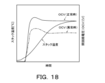
- FIG. 11 is an explanatory diagram showing the time changes of stack temperature and open circuit voltage OCV (normal and abnormal) during startup processing.
- 13 is a flowchart showing an example of an integrated control device side stop process.
- 13 is a flowchart showing an example of a module control device side stop process.
- FIG. 13 is a schematic diagram of a fuel cell system according to another embodiment.
- FIG. 11 is a schematic configuration diagram of a power generation module according to another embodiment.
- FIG. 1 is a schematic diagram of a fuel cell system 10 according to this embodiment
- FIG. 2 is a schematic diagram of a plurality of power generation units 11, each of which includes a power generation module 20 and an auxiliary device 30, and
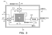
- FIG. 3 is a schematic diagram of a power generation module 20.
- the fuel cell system 10 of the embodiment includes multiple (n) power generation units 11 (first, second, ..., nth power generation unit) and an integrated control device 100 that manages the multiple power generation units 11.
- each of the multiple power generation units 11 includes a power generation module 20 including a fuel cell stack 21, various auxiliary devices 30 required for operation of the fuel cell stack 21, and a module control device 90 that controls the various auxiliary devices 30.
- the power generation module 20 includes a fuel cell stack 21, a combustor 22, and heat exchangers 23 and 24, which are housed in a thermally insulated module case 29.
- the various auxiliary devices 30 include a fuel supply system 40, an air supply system 50, a circulation system 60, and an exhaust heat recovery system 70 (see FIG. 2).
- the fuel cell stack 21 comprises a plurality of solid oxide type single cells each including an electrolyte such as stabilized zirconia (e.g. YSZ), a fuel electrode which is a composite of a catalytic metal such as Ni and stabilized zirconia arranged on one side of the electrolyte, and an air electrode such as LSCF arranged on the other side of the electrolyte.
- Each fuel cell stack 21 generates electricity by reacting hydrogen contained in the fuel gas with oxygen contained in the oxidant gas.
- a temperature sensor 94 is installed near the fuel cell stack 21. The temperature sensor 94 detects a temperature (stack temperature Tst) which correlates with the temperature of the fuel cell stack 21.
- a fuel gas supply pipe 21a is connected to the fuel electrode inlet of the fuel cell stack 21, and a heat exchanger 23 is installed in the fuel gas supply pipe 21a to exchange heat between the fuel gas flowing through the fuel gas supply pipe 21a and the fuel electrode off-gas discharged from the fuel cell stack 21.
- an oxidant gas supply pipe 21b is connected to the air electrode inlet of the fuel cell stack 21, and a heat exchanger 24 is installed in the oxidant gas supply pipe 21b to exchange heat between the air flowing through the oxidant gas supply pipe 21b and the combustion exhaust gas discharged from the combustor 22.
- Hydrogen gas supplied as a fuel gas by the fuel supply system 40 is introduced through a fuel gas supply pipe 21a into the fuel electrode of the fuel cell stack 21, and air supplied as an oxidant gas by the air supply system 50 is introduced through an oxidant gas supply pipe 21b into the air electrode of the fuel cell stack 21. Then, oxide ions (O 2- ) are generated at the air electrode, and the oxide ions permeate the electrolyte and react with hydrogen at the fuel electrode to obtain electric energy.
- the fuel electrode off-gas not used for the electrochemical reaction (power generation) at the fuel electrode of each unit cell is heat exchanged with the fuel gas (hydrogen gas) supplied from the fuel supply system 40 to the fuel electrode in the heat exchanger 23, and then discharged outside the module case 29.
- the fuel electrode off-gas is supplied to the circulation system 60 through the fuel electrode off-gas pipe 62, cooled by a condenser 61 provided in the circulation system 60 to remove water vapor contained in the fuel electrode off-gas, and then supplied to the combustor 22 through the fuel electrode off-gas pipe 63.
- the air electrode off-gas that is not used in the electrochemical reaction (power generation) in the air electrode of each unit cell is directly supplied to the combustor 22.
- the fuel electrode off-gas introduced into the combustor 22 is a combustible gas containing hydrogen, and is mixed with the air electrode off-gas containing oxygen introduced into the combustor 22.
- the mixed gas is burned in the combustor 22, and the fuel cell stack 21 is maintained at an appropriate temperature by the combustion heat.
- the combustor 22 is provided with an ignition device 22f for igniting the mixed gas of fuel gas and air introduced into the combustor 22 during the startup process.
- the combustor 22 generates a combustion exhaust gas, which is heat exchanged with air supplied to the air electrode from the air supply system 50 in the heat exchanger 24, and then supplied to the exhaust heat recovery system 70 through the combustion exhaust gas piping 72. Then, the combustion exhaust gas is discharged to the outside air after the exhaust heat recovery system 70 recovers the exhaust heat.
- the fuel supply system 40 has a hydrogen supply pipe 31 connected at one end to a hydrogen supply source such as a hydrogen tank, a branch pipe 41 branching from the other end of the hydrogen supply pipe 31 to each power generation module 20, and a hydrogen blower 42 installed in each branch pipe 41.
- a hydrogen supply source such as a hydrogen tank
- branch pipe 41 branching from the other end of the hydrogen supply pipe 31 to each power generation module 20
- a hydrogen blower 42 installed in each branch pipe 41.
- the hydrogen supply pipe 31 is equipped with an on-off valve 32 (two-way valve) and a negative pressure prevention valve (not shown), and each branch pipe 41 is equipped with a zero governor 43 (pressure equalizing valve) and a flow sensor 44 in addition to the hydrogen blower 42.
- the flow sensor 44 detects the flow rate per unit time (fuel flow rate Fg) of hydrogen gas (fuel gas) flowing through the branch pipe 41.
- the hydrogen gas introduced into the power generation module 20 is heated by heat exchange with the fuel electrode off-gas in the heat exchanger 23, and then supplied to the fuel electrode of the fuel cell stack 21.
- the air supply system 50 has air supply pipes 51 connected to each power generation module 20, filters 52 provided at the inlets of each air supply pipe 51, and air blowers 53 installed in each air supply pipe 51. By operating the air blowers 53, air is sucked through the filters 52 and the sucked air is pumped (supplied) to the power generation modules 20. Since the air blowers 53 are installed in each air supply pipe 51, the amount of air supplied to each power generation module 20 can be controlled by individually controlling each air blower 53.
- a flow rate sensor 54 is installed in each air supply pipe 51. The flow rate sensor 54 detects the flow rate (air flow rate Fa) of air flowing through the air supply pipe 51 per unit time. The air introduced into the power generation module 20 is heated by heat exchange with the combustion exhaust gas in the heat exchanger 24 , and then supplied to the air electrode of the fuel cell stack 21 .
- the circulation system 60 has a condenser 61 having an individual heat exchange flow path for each power generation module 20, anode off-gas piping 62 connected at one end to each power generation module 20 (fuel electrode side of fuel cell stack 21) and connected at the other end to the inlet of each heat exchange flow path of the condenser 61, anode off-gas piping 63 connected at one end to the outlet of each heat exchange flow path of the condenser 61 and connected at the other end to each power generation module 20 (combustor 22 side), a circulation piping 64 connecting the condenser 61 and the heat utilization device, and a circulation pump 65 installed in the circulation piping 64.
- the anode off-gas discharged from the anode side of the fuel cell stack 21 is supplied to the combustor 22 after the water vapor contained in the anode off-gas is removed in the condenser 61 by heat exchange with the heat exchange medium circulating in the circulation piping 64 by operating the circulation pump 65.
- the circulation system 60 includes a reflux pipe 66 that branches off from the anode off-gas pipe 63 downstream of the condenser 61 and is connected between the hydrogen blower 42 and the zero governor 43 in the branch pipe 41 of the fuel supply system 40, and an adjustment valve 67 (solenoid valve) installed in the reflux pipe 66.
- an adjustment valve 67 solenoid valve
- a portion of the anode off-gas that has passed through the condenser 61 can be refluxed and supplied from the fuel supply system 40 to the power generation module 20.
- an orifice may be provided in the reflux pipe 66 instead of the adjustment valve 67.
- the exhaust heat recovery system 70 has a heat exchanger 71 connected to each combustion exhaust gas pipe 72, a heat storage tank 73, a circulation pipe 74 connecting the heat exchanger 71 and the heat storage tank 73, and a circulation pump 75 installed in the circulation pipe 74.
- the exhaust heat recovery system 70 also has a circulation pipe 76 connecting the heat storage tank 73 and a heat utilization device installed in a factory or the like, and a circulation pump 77 installed in the circulation pipe 76. By operating the circulation pump 77, the heat recovered in the heat storage tank 73 can be supplied to the heat utilization device.
- the fuel cell stacks 21 provided in each of the multiple power generation units 11 are connected in series to a single power conditioner 15, and the DC power generated in each fuel cell stack 21 is converted by the power conditioner 15 and supplied to the load L.
- a voltage sensor 91 for detecting the output voltage of the fuel cell stack 21 is installed between the output terminals of the fuel cell stacks 21 of each power generation module 20.
- a voltage sensor 92 for detecting the voltage of the entire fuel cell stack 21 (total voltage Vt) is installed between one terminal (fuel electrode terminal) of the fuel cell stack 21 located at one end of the fuel cell stacks 21 connected in series and the other terminal (air electrode terminal) of the fuel cell stack 21 located at the other end.
- a current sensor 93 for detecting the current flowing through the power line connecting the fuel cell stacks 21 in series is installed in the power line.
- the power conditioner 15 has a DC/DC converter and an inverter, and converts the DC power from each fuel cell stack 21 into AC power of a voltage (e.g., AC 200V) that can be connected to a system power supply, and outputs it.
- a power supply board (not shown) is connected to the power conditioner 15.
- the power supply board converts the power from each fuel cell stack 21 into DC power suitable for driving the various auxiliary devices 30, the module control device 90, and the integrated control device 100, and supplies it to each of them.
- a cooling fan and a ventilation fan (not shown) for cooling the power conditioner 15 and the power supply board are arranged in the auxiliary device room where the power conditioner 15 and the power supply board are arranged.
- Each module control device 90 is configured as a microprocessor centered on a CPU (not shown), and in addition to the CPU, it is equipped with a ROM for storing processing programs, a RAM for temporarily storing data, an input/output port, and a communication port.
- Each module control device 90 receives, via an input port, the stack temperature Tst from a temperature sensor 94 installed near the corresponding fuel cell stack 21, the voltage V from a voltage sensor 91 installed between the output terminals of the corresponding fuel cell stack 21, the fuel flow rate Fg from a flow rate sensor 44 installed in the corresponding branch pipe 41 of the fuel supply system 40, the air flow rate Fa from a flow rate sensor 54 installed in the corresponding air supply pipe 51 of the air supply system 50, and the like.
- each module control device 90 outputs, via an output port, a control signal to the corresponding hydrogen blower 42 of the fuel supply system 40, a control signal to the corresponding air blower 53 of the air supply system 50, a control signal to the corresponding adjustment valve 67 of the circulation system 60, and the like.
- the integrated control device 100 is configured as a microprocessor with a CPU 101 at its core, and in addition to the CPU 101, it is equipped with a ROM 102 for storing processing programs, a RAM 103 for temporarily storing data, an EEPROM 104 as a non-volatile memory, a timer (not shown), an input/output port, and a communication port (not shown).
- the total voltage Vt detected by the voltage sensor 92 and the current I from the current sensor 93 are input to the integrated control device 100 via the input port.
- the integrated control device 100 outputs control signals to the on-off valve 32, control signals to the circulation pump 65 of the circulation system 60, and control signals to the circulation pumps 75 and 77 of the exhaust heat recovery system 70 via the output port.
- the integrated control device 100 is also connected to each module control device 90 via a communication bus 12 so as to be able to communicate with each other, and exchanges control signals and data with each other.
- each module controller 90 When the start-up of the fuel cell system 10 is requested from the higher-level system, each module controller 90 performs start-up processing in response to an instruction from the integrated controller 100. In the start-up processing, each module controller 90 sequentially controls the auxiliary devices 30 to perform purging processing of the combustor 22, etc., and then supplies fuel gas (hydrogen gas) and air to the combustor 22, and performs warm-up processing to warm up the fuel cell stack 21 by burning the fuel gas in the combustor 22.
- fuel gas hydrogen gas
- each module controller 90 transitions to power generation processing in response to an instruction from the integrated controller 100.
- the fuel cell stacks 21 of each power generation module 20 are connected in series to the load L, and current flows through all the fuel cell stacks 21 when the current sweep is started, so power generation must be started simultaneously. For this reason, the transition to power generation processing is performed after all the fuel cell stacks 21 have completed warm-up and reached a power generation possible state.
- each module controller 90 inputs the target fuel flow rate Fgtag and the target air flow rate Fatag set by the integrated controller 100 based on the required power for the entire fuel cell system 10, and controls the corresponding hydrogen blower 42 and air blower 53 based on the input target flow rates. Specifically, each module controller 90 controls the drive of the hydrogen blower 42 by feedback control based on the difference between the target fuel flow rate Fgtag and the fuel flow rate Fg detected by the flow sensor 44, and controls the drive of the air blower 53 by feedback control based on the difference between the target air flow rate Fatag and the air flow rate Fa detected by the flow sensor 54.
- each module controller 90 When a request to shut down the fuel cell system 10 is made, each module controller 90 performs a shutdown process in response to an instruction from the integrated controller 100. In the shutdown process, each module controller 90 controls the hydrogen blower 42 so that fuel gas is supplied at a flow rate that does not cause oxidation degradation of the electrodes of the fuel cell stack 21, and controls the air blower 53 so that air is supplied at a flow rate necessary to cool the fuel cell stack 21. Then, when the stack temperature Tst from the temperature sensor 94 falls below a predetermined temperature, each module controller 90 stops the supply of fuel gas and air.
- FIG 4 is a flowchart showing an example of the integrated control device side startup process executed by the integrated control device 100
- Figure 5 is a flowchart showing an example of the module control device side startup process executed by each module control device 90.
- the integrated control device 100 When the integrated control device side startup process is executed, the integrated control device 100 (CPU 101) first instructs all module control devices 90 to perform pre-warm-up preparations (step S100).
- the integrated control device 100 when each module control device 90 receives a pre-warm-up preparation instruction from the integrated control device 100 ("YES" in step S150), it checks whether the various auxiliaries 30 and various sensors of the corresponding power generation unit 11 are operating normally and whether the temperature of the fuel cell stack 21 (stack temperature Tst) is within an appropriate range as pre-warm-up preparations (step S152), and then sends a notification to the integrated control device 100 that operation is possible (operation possible notification) (step S154), and proceeds to step S156.
- the integrated control device 100 judges whether or not it has received an operation possible notification from each module control device 90 (step S102). If the integrated control device 100 judges that it has not received an operation possible notification, it returns to step S102 and repeats the reception judgment. On the other hand, if the integrated control device 100 judges that it has received an operation possible notification, it judges whether or not it has received an operation possible notification from all module control devices 90 (step S104). If the integrated control device 100 judges that it has not received an operation possible notification from any module control device 90, it returns to step S102. On the other hand, if the integrated control device 100 judges that it has received an operation possible notification from all module control devices 90, it opens the opening/closing valve 32 to enable the supply of fuel gas (hydrogen) to each fuel cell stack 21 (step S106).
- the integrated control device 100 sets a warm-up start waiting time for each fuel cell stack 21 (step S108).
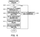
- the warm-up start waiting time is set by the integrated control device 100 executing a warm-up start waiting time setting process illustrated in FIG. 6.
- the warm-up start waiting time setting process will be described later.
- the integrated control device 100 then instructs the corresponding module control device 90 to perform a warm-up operation for the fuel cell stack 21 whose warm-up start waiting time is zero (step S110), and starts measuring the elapsed time (step S112).
- the integrated control device 100 determines whether or not the warm-up start waiting time for any of the remaining fuel cell stacks 21 for which a warm-up operation has not yet been instructed has elapsed, based on the elapsed period and the warm-up start waiting time set for each fuel cell stack 21 (step S114). If the integrated control device 100 determines that the warm-up start waiting time has not elapsed for any of the remaining fuel cell stacks 21, it returns to step S114. On the other hand, if the integrated control device 100 determines that the warm-up start waiting time has elapsed for any of the remaining fuel cell stacks 21, it instructs the corresponding module control device 90 to perform a warm-up operation for the corresponding fuel cell stack 21 (step S116).
- step S118 the integrated control device 100 determines whether or not the warm-up operation instructions for all of the fuel cell stacks 21 have been completed. If the integrated control device 100 determines that the warm-up operation command has not been completed for any of the fuel cell stacks 21, it returns to step S114. On the other hand, if the integrated control device 100 determines that the warm-up operation command has been completed for all of the fuel cell stacks 21, it proceeds to step S120.
- Each module control device 90 waits to receive a warm-up operation instruction from the integrated control device 100 (step S156).
- each module control device 90 determines that it has received a warm-up operation instruction, it starts the warm-up operation (step S158) and starts measuring the elapsed time (step S160).
- the warm-up operation is performed by controlling the hydrogen blower 42 and the air blower 53 so that fuel gas (hydrogen) and air are supplied to the fuel cell stack 21 (combustor 22) with a fuel concentration within the combustion range, then driving the igniter of the ignition device 22f to combust the fuel gas in the combustor 22, and continuing to supply the fuel gas and air until the warm-up of the fuel cell stack 21 is completed and the fuel cell stack 21 is in a power generation possible state.
- the supply amount of fuel gas during the warm-up operation is controlled, for example, by setting a target fuel flow rate Fgtag at each of multiple timings (sequences) from the start to the completion of the warm-up operation, and controlling the hydrogen blower 42 so that the fuel flow rate Fg from the flow rate sensor 44 matches the target fuel flow rate Fgtag at that time.
- each module control device 90 judges whether or not the stack temperature Tst from the corresponding temperature sensor 94 is equal to or higher than the threshold value ⁇ (step S162).
- the threshold value ⁇ is a threshold value for judging whether or not the fuel cell stack 21 has completed warming up.
- each module control device 90 judges that the stack temperature Tst is not equal to or higher than the threshold value ⁇ , it judges that the fuel cell stack 21 has not yet reached a power generation possible state, and returns to step S162.
- each module control device 90 judges that the stack temperature Tst is equal to or higher than the threshold value ⁇ , it judges that the warm-up has been completed and the fuel cell stack 21 has reached a power generation possible state, and transmits a notice that power generation is possible (power generation possible notice) and the elapsed time since the start of the warm-up operation (warm-up required time) to the integrated control device 100 (step S164).
- each module control device 90 performs a reduction correction to reduce the amount of fuel gas supplied (step S166) while waiting for a power generation command to be received from the integrated control device 100 (step S168).
- the reduction correction of the fuel gas is performed within a range in which combustion in the combustor 22 is maintained and the temperature of the fuel cell stack 21 does not fall below an appropriate temperature. This makes it possible to reduce unnecessary fuel consumption after the corresponding fuel cell stack 21 reaches a power generation capable state compared to supplying the same amount of fuel gas as before the power generation capable state.
- the integrated control device 100 After instructing the warm-up operation in steps S110 to S118, the integrated control device 100 waits to receive a power generation possible notification from any of the module control devices 90 (step S120). When the integrated control device 100 determines that a power generation possible notification has been received, it associates the warm-up time received together with the power generation possible notification with the corresponding fuel cell stack 21 and stores it in the EEPROM 104 (step S122). Then, the integrated control device 100 determines whether or not a power generation possible notification has been received from all of the module control devices 90 (step S124). When the integrated control device 100 determines that a power generation possible notification has not been received from any of the module control devices 90, it returns to step S120 and repeats the processing of steps S120 to S124.
- the integrated control device 100 determines that a power generation possible notification has been received from all of the module control devices 90, it controls the power conditioner 15 to start a current sweep (step S126), instructs all of the module control devices 90 to start a power generation operation (step S128), and ends the integrated control device side startup processing. Meanwhile, after transmitting the notification that power generation is possible to the integrated control device 100, each module control device 90 waits to receive a power generation operation instruction from the integrated control device 100 (step S168). Then, when each module control device 90 determines that it has received a power generation operation instruction, it starts a power generation operation (step S170) and ends the module control device side startup process. Details of the control of the power generation operation have been described above.
- the integrated control device 100 first determines whether or not the current startup of the fuel cell system 10 is the first time (step S200). If the integrated control device 100 determines that the current startup is the first time, it sets an initial value to the warm-up start waiting time of each fuel cell stack 21 (step S202) and ends the warm-up start waiting time setting process.
- the initial value is determined for each fuel cell stack 21 and is stored in advance in the EEPROM 104. For example, the initial value is set to a warm-up start waiting time experimentally determined so that the warm-up of each fuel cell stack 21 is completed at the same timing. Note that the initial value may be set to a value of 0 for each fuel cell stack 21.
- the integrated control device 100 determines that this is not the first startup, it reads out the past warm-up required time for each fuel cell stack 21 from the EEPROM 104 (step S204). If the system has been started up multiple times in the past, the warm-up required time read out from the EEPROM 104 may be the average warm-up required time for each of the previous startups, or may be the warm-up required time for the most recent startup. Next, the integrated control device 100 sets the warm-up start waiting time of the fuel cell stack 21 with the longest warm-up required time to a value of 0 (step S206).
- the integrated control device 100 sets the longest warm-up required time to a reference time (step S208), and calculates the time difference between the warm-up required time of each of the remaining fuel cell stacks 21 and the reference time (step S210). Then, the integrated control device 100 sets the warm-up start waiting time of each of the remaining fuel cell stacks 21 to a time corresponding to the corresponding time difference (step S212), and ends the warm-up start waiting time setting process.
- the warm-up start waiting time may be set by directly setting the time difference as the warm-up start waiting time, or by multiplying the time difference by a coefficient greater than 0 and less than 1 and setting the warm-up start waiting time as the warm-up start waiting time.
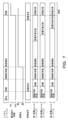
- FIG. 7 is an explanatory diagram showing the time change of the sequence of each power generation unit in the comparative example
- FIG. 8 is an explanatory diagram showing the time change of the sequence of each power generation unit in this embodiment.
- FIG. 9 is an explanatory diagram showing the cumulative fuel consumption during warm-up operation of each power generation unit in the comparative example
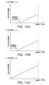
- FIG. 10 is an explanatory diagram showing the cumulative fuel consumption during warm-up operation of each power generation unit in this embodiment
- FIG. 11 is an explanatory diagram showing the cumulative fuel consumption when the combustion supply amount of the power generation unit that has completed warm-up earlier than the others is reduced.
- FIG. 10 is an explanatory diagram showing the cumulative fuel consumption during warm-up operation of each power generation unit in this embodiment
- FIG. 11 is an explanatory diagram showing the cumulative fuel consumption when the combustion supply amount of the power generation unit that has completed warm-up earlier than the others is reduced.
- the integrated control device 100 simultaneously instructs all module control devices 90 to start warm-up so that all fuel cell stacks 21 of n power generation units 11 (first, second, ..., nth power generation unit) connected in series start warm-up operation at the same time.
- the integrated control device 100 instructs each module control device 90 to start warm-up at different timings so that all fuel cell stacks 21 complete warm-up operation at the same time and reach a power generation possible state.
- n power generation units 11 are provided, and since the installation position of the fuel cell stack 21, the tolerance of the auxiliary equipment 30, and the degree of deterioration of the fuel cell stack 21 differ for each power generation unit 11, the progress of warming up (the rate of increase of the stack temperature Tst) varies for each fuel cell stack 21. For this reason, even if the warm-up operation is started simultaneously for all the fuel cell stacks 21, the warm-up may not be completed simultaneously. In this case, as shown in FIG.
- the integrated control device 100 sets a warm-up start waiting time for each fuel cell stack 21, and instructs the corresponding module control device 90 to start the warm-up operation when each warm-up start waiting time has elapsed. As a result, as shown in FIG.
- all fuel cell stacks 21 can be warmed up at the same time, and unnecessary fuel and power consumption can be prevented.
- a reduction correction is performed to reduce the amount of fuel gas supplied to the corresponding fuel cell stack 21 (step S166 of the module control device side startup process), and unnecessary fuel consumption can be minimized (see FIG. 11).
- the multiple fuel cell stacks 21 when all of the multiple fuel cell stacks 21 connected in series have reached a power generation state, a current sweep is started to cause the multiple fuel cell stacks 21 to generate power simultaneously. This prevents current sweeping from some of the low-temperature fuel cell stacks 21, thereby suppressing deterioration of the fuel cell stacks 21. Furthermore, the start timing of the warm-up operation of the multiple fuel cell stacks 21 is adjusted so that the multiple fuel cell stacks 21 reach a power generation state at the same time. If the multiple fuel cell stacks 21 reach a power generation state at different times, unnecessary fuel consumption occurs in the fuel cell stack 21 that first reached a power generation state to maintain the power generation state. In this embodiment, by adjusting the start timing of the warm-up operation of the multiple fuel cell stacks 21, the multiple fuel cell stacks 21 can reach a power generation state at the same time, suppressing the occurrence of unnecessary fuel consumption.
- the warm-up time required for each of the fuel cell stacks 21 to reach a power generation state when the system was started in the past is stored in the EEPROM 104, and the warm-up start waiting time for the multiple fuel cell stacks 21 is set based on the past warm-up time so that the multiple fuel cell stacks 21 will reach a power generation state at the same time when the system is started next time onwards.
- the initial value of the warm-up start waiting time for each fuel cell stack 21 is stored in advance in the EEPROM 104, and the initial value is set for the warm-up start waiting time when the system is started for the first time, so that the multiple fuel cell stacks 21 can reach a power generation state at the same time even when the system is started for the first time.
- the amount of fuel gas supplied to the fuel cell stack 21 that has completed warm-up operation first among the multiple fuel cell stacks 21 is reduced compared to the amount of fuel gas supplied to that fuel cell stack 21 during the warm-up operation, thereby suppressing unnecessary fuel consumption.
- each module control device 90 supplies fuel gas according to a preset target fuel flow rate Fgtag at multiple timings (sequences) from the start to the end of the warm-up operation.
- the amount of fuel gas supplied may be adjusted by monitoring the temperature gradient (amount of change per unit time in stack temperature Tst) of the fuel cell stack 21 during warm-up operation.
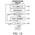
- Figure 12 is a flowchart showing an example of a warm-up fuel supply adjustment process. This process is executed by each module control device 90 when each of the multiple timings (sequences) described above occurs after the warm-up operation is started.
- each module control device 90 inputs the stack temperature Tst from the temperature sensor 94 (step S300), and calculates the temperature gradient by taking the difference between the stack temperature Tst input this time and the stack temperature input last time (step S302). Then, each module control device 90 judges whether the calculated temperature gradient is greater than a threshold value obtained by adding a slight margin value ⁇ to the target gradient (step S304).
- the target gradient is the temperature gradient required for the warm-up of the fuel cell stack 21 to be completed at the target timing. If each module control device 90 judges that the temperature gradient is greater than the threshold value, it performs a reduction correction to reduce the amount of fuel gas supply (target fuel flow rate Fgtag) (step S306).
- each module control device 90 judges whether the temperature gradient is equal to or less than the threshold value, it skips step S306. Then, each module control device 90 judges whether the stack temperature Tst is equal to or greater than the threshold value ⁇ , that is, whether the warm-up of the fuel cell stack 21 has been completed (step S308). If each module control device 90 determines that warm-up is not complete, it returns to step S300 and repeats the processes of steps S300 to S308. If it determines that warm-up is complete, it ends the warm-up fuel supply amount adjustment process. This allows the temperature of each fuel cell stack 21 (stack temperature Tst) to be raised according to the respective target gradient.
- each module control device 90 may perform an increase correction to increase the fuel gas supply amount (target fuel flow rate Fgtag) within a range not exceeding the upper limit amount when the temperature gradient is smaller than a threshold value obtained by subtracting a margin value ⁇ from the target gradient.
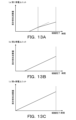
- FIG. 13 is an explanatory diagram showing the cumulative fuel consumption when warming up each power generation unit 11 according to the target gradient
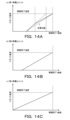
- FIG. 14 is an explanatory diagram showing the change in stack temperature when warming up each power generation unit according to the target gradient.
- the module control device 90 adjusts the amount of fuel gas supply (target fuel flow rate Fgtag) so that the temperature gradient approaches the target gradient. This makes it possible to complete the warming up of all fuel cell stacks 21 simultaneously and suppress unnecessary fuel consumption.
- each module control device 90 may set the target temperature of the fuel cell stack 21 in stages at multiple timings (sequences) from the start to the completion of the warm-up operation, and set the target fuel flow rate Fgtag so that the stack temperature Tst matches the target temperature at that time, and control the hydrogen blower 42 to complete the warm-up of all fuel cell stacks 21 simultaneously.
- FIG. 15 is a flowchart showing an example of a warm-up fuel supply amount adjustment process.
- each module control device 90 inputs the stack temperature Tst (own stack temperature) of its own fuel cell stack 21 (own stack) from the temperature sensor 94 (step S350) and acquires the stack temperature Tst (other stack temperature) of another fuel cell stack 21 (other stack) (step S352).
- the other stack temperature can be acquired by communication via the integrated control device 100 from the module control device 90 that inputs the stack temperature Tst from the temperature sensor 94 provided in the other stack. Then, each module control device 90 determines whether or not the own stack temperature is greater than a threshold value obtained by adding a predetermined margin value ⁇ to the other stack temperature (step S354). When each module controller 90 determines that its own stack temperature is greater than the threshold, it performs a reduction correction to reduce the fuel gas supply amount (target fuel flow rate Fgtag) (step S356). On the other hand, when each module controller 90 determines that its own stack temperature is equal to or less than the threshold, it skips step S356.
- each module controller 90 determines whether or not the stack temperature Tst is equal to or greater than the threshold ⁇ , that is, whether or not the warm-up of the fuel cell stack 21 has been completed (step S358).
- each module controller 90 determines that the warm-up has not been completed, it returns to step S350 and repeats the processes of steps S350 to S358.
- it determines that the warm-up has been completed it ends the warm-up fuel supply amount adjustment process. This allows the own stack temperature to match the other stack temperatures, and makes it possible to simultaneously complete the warm-up of all the fuel cell stacks 21.
- Each module control device 90 may perform an increase correction to increase the fuel gas supply amount of a fuel cell stack 21 that is slow to warm up among the multiple fuel cell stacks 21, within a range not exceeding the upper limit amount relative to the fuel gas supply amount of a fuel cell stack 21 that is warming up more quickly.
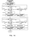
- FIG. 16 is a flowchart showing an example of the integrated control device side startup process executed by the integrated control device 100
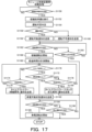
- FIG. 17 is a flowchart showing an example of the module control device side startup process executed by each module control device 90.
- the integrated control device 100 (CPU 101) first instructs all module control devices 90 to perform pre-warm-up preparation (step S1100). Meanwhile, in the module control device side startup process, each module control device 90 waits to receive a pre-warm-up preparation instruction from the integrated control device 100 (step S1150). Next, as pre-warm-up preparation, each module control device 90 checks whether the various auxiliary devices 30 and various sensors of the corresponding power generation unit 11 are operating normally, and checks whether the temperature of the fuel cell stack 21 (stack temperature Tst) is within an appropriate range (step S1152), and determines whether the corresponding fuel cell stack 21 can be operated (step S1154).
- each module control device 90 determines that the corresponding fuel cell stack 21 can be operated ("YES” in step S1156), it transmits a notification that the corresponding fuel cell stack 21 can be operated (operation possible notification) to the integrated control device 100 (step S1158), and proceeds to step S1162.
- each module control device 90 determines that the corresponding fuel cell stack 21 cannot be operated ("NO” in step S1156), it sends a notification that the corresponding fuel cell stack 21 cannot be operated (notification of inoperability) to the integrated control device 100 (step S1160) and proceeds to step S1162.
- the integrated control device 100 determines whether or not it has received an operation possible notification from each module control device 90 (step S1102) and whether or not it has received an operation impossible notification (step S1104). If the integrated control device 100 determines that it has not received any notification, it returns to step S1102 and repeats the reception determination. On the other hand, if the integrated control device 100 determines that it has received an operation possible notification, it determines whether or not it has received an operation possible notification from all module control devices 90 (step S1106). If the integrated control device 100 determines that it has not received an operation possible notification from any module control device 90, it returns to step S1102.
- the integrated control device 100 determines that it has received an operation possible notification from all module control devices 90, it opens the on-off valve 32 to enable the supply of fuel gas (hydrogen) to each fuel cell stack 21 (step S1108), instructs all module control devices 90 to perform warm-up operation (step S1110), and proceeds to step S1114.
- the integrated control device 100 determines in step S1104 that it has received an operation impossible notification from any of the module control devices 90, it instructs all the module control devices 90 to stop starting (step S1112) and ends the integrated control device side start-up process.
- Each module control device 90 determines whether it has received a warm-up operation instruction from the integrated control device 100 (step S1162) and whether it has received a start-up stop instruction (step S1164). When each module control device 90 determines that it has not received any instruction, it returns to step S1162 and repeats the reception determination. When each module control device 90 determines that it has received a start-up stop instruction, it ends the module control device side start-up process without performing a warm-up operation. On the other hand, when each module control device 90 determines that it has received a warm-up operation instruction, it starts a warm-up operation (step S1166) and starts measuring the elapsed time (step S1168).
- Warm-up operation is performed by controlling the hydrogen blower 42 and air blower 53 so that fuel gas (hydrogen) and air are supplied to the fuel cell stack 21 (combustor 22) at a fuel concentration within the combustion range, then driving the igniter of the ignition device 22f to combust the fuel gas in the combustor 22, and continuing to supply fuel gas and air until the warm-up of the fuel cell stack 21 is complete and it is ready to generate electricity.
- each module control device 90 determines whether the stack temperature Tst from the corresponding temperature sensor 94 is equal to or greater than the threshold value ⁇ (step S1170) and whether the voltage (open circuit voltage OCV) from the corresponding voltage sensor 91 is equal to or greater than the threshold value ⁇ (step S1172).
- the threshold values ⁇ and ⁇ are threshold values for determining whether the fuel cell stack 21 is in a state capable of generating electricity.
- each module control device 90 determines whether the stack temperature Tst is not equal to or greater than the threshold value ⁇ , or that the stack temperature Tst is equal to or greater than the threshold value ⁇ but the open circuit voltage OCV is not equal to or greater than the threshold value ⁇ (steps S1174, S1176).
- the threshold value ⁇ is set to a time longer than the time normally required to complete the warm-up of the fuel cell stack 21.
- each module controller 90 determines that the stack temperature Tst is equal to or greater than the threshold value ⁇ and the open circuit voltage OCV is equal to or greater than the threshold value ⁇ , it determines that the warm-up operation of the fuel cell stack 21 has been completed normally, transmits a notice to the integrated controller 100 that power generation is possible (power generation possible notice) (step S1182), and proceeds to step S1184.
- each module controller 90 determines that the stack temperature Tst is not equal to or greater than the threshold value ⁇ and determines that the elapsed time is equal to or greater than the threshold value ⁇ , it determines that an abnormality has occurred in the auxiliary device 30, transmits a notice to the integrated controller 100 that a timeout error has occurred together with the details of the abnormality and the identification information of the power generation module 20 in which the abnormality has occurred (timeout error notice) (step S1178), and ends the module controller side startup process.
- each module control device 90 determines that the stack temperature Tst is equal to or greater than the threshold ⁇ , the open circuit voltage OCV is not equal to or greater than the threshold ⁇ , and the elapsed time is equal to or greater than the threshold ⁇ , it determines that the open circuit voltage OCV has not risen sufficiently and that the fuel cell stack 21 has deteriorated, and transmits a timeout error notification to the integrated control device 100 together with the details of the abnormality and the identification information of the power generation module 20 in which the abnormality has occurred (step S1180), and ends the module control device side startup process. As shown in FIG.
- the open circuit voltage OCV rises sharply, and then, as the warm-up progresses, the open circuit voltage OCV converges to a constant value and the stack temperature Tst gradually rises.
- the open circuit voltage OCV becomes lower than normal, so that the presence or absence of deterioration of the fuel cell stack 21 can be diagnosed by checking the open circuit voltage OCV when the elapsed time from the start of the warm-up operation reaches or exceeds the threshold ⁇ (a time longer than the time normally required to complete the warm-up).
- the integrated control device 100 determines whether or not it has received a power generation possible notification from any of the module control devices 90 (step S1114) and whether or not it has received a timeout error notification (step S1116). If the integrated control device 100 determines that it has not received any notification, it returns to step S1114 and repeats the reception determination. On the other hand, if the integrated control device 100 determines that it has received a power generation possible notification, it determines whether or not it has received a power generation possible notification from all of the module control devices 90 (step S1118). If the integrated control device 100 determines that it has not yet received a power generation possible notification from any of the module control devices 90, it returns to step S1114.
- the integrated control device 100 determines that it has received a power generation possible notification from all of the module control devices 90, it controls the power conditioner 15 to start a current sweep (step S1120), instructs all of the module control devices 90 to perform a power generation operation (step S1122), and ends the integrated control device side startup process.
- the integrated control device 100 judges that it has received a timeout error notification from any of the module control devices 90, it stores the contents of the abnormality and the identification information of the power generation module 20 in which the abnormality has occurred in the EEPROM 104 (step S1124), instructs all the module control devices 90 to stop operation (step S1126), and ends the integrated control device side startup process.
- each module control device 90 judges whether or not it has received a power generation operation instruction (step S1184) and whether or not it has received a stop operation instruction (step S1186). When each module control device 90 judges that it has not received any instruction, it returns to step S1184 and repeats the reception judgment. On the other hand, when each module control device 90 judges that it has received a power generation operation instruction, it starts a power generation operation (step S1188) and ends the module control device side startup process. The details of the control of the power generation operation have been described above. When each module control device 90 judges that it has received a stop operation instruction, it ends the module control device side startup process as it is. The stop operation is performed by the module control device side stop process described below. The details of the start process have been explained above.
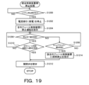
- Figure 19 is a flowchart showing an example of the integrated control device side stop processing executed by the integrated control device 100
- Figure 20 is a flowchart showing an example of the module control device side stop processing executed by each module control device 90.
- the integrated control device 100 (CPU 101) first waits for a request to stop the system from the upper system (step S1200).
- the integrated control device 100 determines that a request to stop the system has been made, it controls the power conditioner 15 to stop the current sweep from each fuel cell stack 21 (step S1202) and instructs all module control devices 90 to stop operation (step S1204).
- each module control device 90 when each module control device 90 receives a stop operation instruction from the integrated control device 100 (step S1250), it starts supplying air at a predetermined flow rate required to cool the corresponding fuel cell stack 21 (step S1252) and starts supplying fuel gas at a flow rate at which the combustion region of the combustor 22 has a concentration below the lower combustion limit (step S1252). Then, each module control device 90 starts measuring the elapsed time (step S1256).
- each module control device 90 determines whether or not an immediate stop command, which will be described later, has been received (step S1258), whether or not the stack temperature Tst is less than threshold A (step S1260), and whether or not the elapsed time is equal to or greater than threshold B (step S1262).
- threshold A is set to a value close to the lower limit of the temperature range in which catalytic oxidation of the fuel cell stack 21 progresses.
- Threshold B is set to a time longer than the time normally required for the stack temperature Tst to fall below threshold A during stopped operation.
- each module control device 90 determines that an immediate stop command has not been received, that the stack temperature Tst is not less than threshold A, and that the elapsed time is not equal to or greater than threshold B, the process returns to step S1258, and the reception determination is repeated.
- each module control device 90 determines that it has not received an immediate stop command and that the stack temperature Tst is less than the threshold A, it determines that cooling of the fuel cell stack 21 is complete, stops the supply of air and fuel gas (step S1264), sends a notice to the integrated control device 100 that the stop operation is complete (stop completion notice) (step S1266), and ends the module control device side stop processing.
- each module control device 90 determines that it has not received an immediate stop command, determines that the stack temperature Tst is not less than the threshold A, and determines that the elapsed time is equal to or greater than the threshold B, it determines that it has not been possible to cool the fuel cell stack 21 and that the system cannot be stopped by normal stop operation, sends a timeout error notice to the integrated control device 100 (step S1268), and returns to step S1258.
- Cases in which it is not possible to cool the fuel cell stack 21 include cases where the amount of air supply is insufficient or the amount of fuel gas supply is excessive and combustion in the combustor 22 is maintained, and in either case it is determined that there is a risk of an abnormality occurring in the auxiliary device 30.
- the integrated control device 100 determines whether a stop completion notification has been received from any of the module control devices 90 (step S1206) and whether a timeout error notification has been received (step S1208). If the integrated control device 100 determines that no notification has been received, it returns to step S1206 and repeats the reception determination. On the other hand, if the integrated control device 100 determines that a stop completion notification has been received, it determines whether a stop completion notification has been received from all of the module control devices 90 (step S1210). If the integrated control device 100 determines that a stop completion notification has not been received from any of the module control devices 90, it returns to step S1206.
- the integrated control device 100 determines that a stop completion notification has been received from all of the module control devices 90, it closes the on-off valve 32 (step S1212) and ends the integrated control device side stop processing.
- the integrated control device 100 determines that it has received a timeout error notification from any of the module control devices 90, it sends an immediate stop instruction to the module control device 90 that sent the timeout error notification (step S1214), and ends the integrated control device side stop processing.
- the module control device 90 that received the immediate stop instruction immediately stops the supply of air and fuel gas (step S1264), sends a stop completion notification (step S1266), and ends the module control device side stop processing.
- the integrated control device 100 starts a current sweep and instructs all module control devices 90 to start power generation operation of the corresponding fuel cell stacks 21 based on the fact that the integrated control device 100 has received a notification from all of the multiple module control devices 90 that the corresponding fuel cell stacks 21 are capable of generating power (power generation possible notification) during the startup process.
- This makes it possible to avoid excessive current flowing from the low-temperature fuel cell stacks 21 when starting the current sweep, and more reliably suppress deterioration of the fuel cell stacks 21.
- each module control device 90 determines whether the corresponding fuel cell stack 21 (power generation unit 11) is operable and transmits the result of the determination (operable notification or inoperable notification) to the integrated control device 100, and based on receiving operational notifications from all module control devices 90, the integrated control device 100 instructs all module control devices 90 to start warm-up operations of the corresponding fuel cell stacks 21. This makes it possible to avoid starting warm-up operations of the other fuel cell stacks 21 when any of the multiple fuel cell stacks 21 connected in series is not in an operational state.
- each module control device 90 transmits a power generation possible notification to the integrated control device 100 when the temperature (stack temperature Tst) of the corresponding fuel cell stack 21 is equal to or higher than the threshold value ⁇ and the open circuit voltage OCV of the corresponding fuel cell stack 21 is equal to or higher than the threshold value ⁇ before the elapsed time since the start of the warm-up operation reaches the threshold value ⁇ .
- each module control device 90 determines that the corresponding fuel cell stack 21 has deteriorated and transmits a notification of a timeout (timeout error notification) to the integrated control device 100 when the elapsed time since the start of the warm-up operation reaches the threshold value ⁇ before the stack temperature Tst reaches the threshold value ⁇ or higher, and transmits a timeout error notification to the integrated control device 100 when the elapsed time since the start of the warm-up operation reaches the threshold value ⁇ before the open circuit voltage OCV reaches the threshold value ⁇ or higher. Then, when the integrated control device 100 receives a timeout error notification from any of the module control devices 90, it instructs all the module control devices 90 to stop operation.
- a timeout error notification a notification of a timeout
- each module control device 90 performs a shutdown operation to supply fuel gas and air to the corresponding fuel cell stack 21 within a range below the lower combustion limit, and when the temperature (stack temperature Tst) of the corresponding fuel cell stack 21 falls below threshold A, it stops the supply of fuel gas and air and sends a notification (shutdown completion notification) to the integrated control device 100 that the shutdown operation has been completed. If the elapsed time since the shutdown operation began reaches threshold B before the stack temperature Tst falls below threshold A, it sends a notification (timeout error notification) to the integrated control device 100 that the shutdown operation has not been completed.
- the integrated control device 100 When the integrated control device 100 receives a timeout error notification from any of the module control devices 90, it instructs the corresponding module control device 90 to perform an immediate shutdown operation. This makes it possible to appropriately respond to cases where the shutdown operation cannot be completed in any of the multiple fuel cell stacks 21 connected in series.
- the fuel supply system 40 supplies hydrogen gas as the fuel gas to the fuel electrode of the fuel cell stack 21, but raw fuel gas such as natural gas or LP gas may be reformed into a fuel gas containing hydrogen gas and supplied to the fuel electrode of the fuel cell stack 21.
- the fuel supply system may include a gas pump that pressurizes the raw fuel gas to the branch pipe 41 and a desulfurizer that removes sulfur components from the raw fuel gas, an evaporator that receives a supply of water (reforming water) inside the module case 29 to generate water vapor, and a reformer that uses the water vapor from the evaporator to reform the raw fuel gas into fuel gas.
- each fuel cell stack 21 performs a power generation operation in which electricity is generated by a reaction between hydrogen and oxygen contained in air.
- the fuel cell stack 21 may be a reversible operation solid oxide cell stack, and may have an FC mode in which a power generation operation is performed, and an EC mode in which an electrolysis operation is performed in which hydrogen is produced by high-temperature steam electrolysis while power is supplied from a power source.
- the power source may be a system power source, a renewable energy source such as a solar power generation device, a storage battery, or the like.
- FIG. 21 is a schematic diagram of a fuel cell system 10B according to another embodiment
- FIG. 22 is a schematic diagram of the power generation module 20.
- the power generation module 20 includes an evaporator 25 in addition to a fuel cell stack 21, a combustor 22, and heat exchangers 23 and 24, which are housed in a module case 29 having thermal insulation properties.
- the evaporator 25 may be provided with a heater to compensate for heat shortage in the evaporator 25.
- the various auxiliary devices 30 include a fuel supply system 40, an air supply system 50, a circulation system 60, an exhaust heat recovery system 70, and a water supply system 80.
- the water supply system 80 has a water tank 81 that stores water (raw water), a water supply pipe 82 connected at one end to the water tank 81, branch pipes 83 that branch off from the other end of the water supply pipe 82 to each power generation module 20, and a water pump 84 installed in each branch pipe 83.
- the water pump 84 By operating the water pump 84, the raw water in the water tank 81 is pumped (supplied) to the power generation module 20. Since the water pump 84 is installed in each branch pipe 83, the supply amount of raw water for each power generation module 20 can be controlled by individually controlling each water pump 84.
- An evaporator 25 is connected between the branch pipe 83 of the water supply system 80 and the fuel gas supply pipe 21a. The raw water is evaporated in the evaporator 25 and converted into steam.
- water vapor and a small amount of hydrogen gas are supplied as fuel gas from the water supply system 80 and the fuel supply system 40 to the fuel electrode of the fuel cell stack 21 through the fuel gas supply pipe 21a, and air is supplied as sweep gas from the air supply system 50 to the air electrode of the fuel cell stack 21 through the oxidizer gas supply pipe 21b.
- a power source supplies a predetermined voltage between the terminals of the fuel cell stack 21 (reversible operation solid oxide cell stack)
- the water vapor introduced to the fuel electrode is decomposed into hydrogen and oxygen ions (O 2- ) by electrolysis at the fuel electrode, and oxygen is generated at the air electrode by the oxygen ions permeating the electrolyte.
- a small amount of hydrogen gas is also supplied to the fuel electrode together with water vapor, so that the fuel electrode is kept in a reducing atmosphere and oxidation deterioration of the fuel electrode can be suppressed.
- the hydrogen gas generated at the fuel electrode is discharged as fuel electrode off-gas together with water vapor that has not reacted in the electrolysis, and is heat-exchanged with water vapor, etc., supplied to the fuel electrode from the water supply system 80 in the heat exchanger 23 before being discharged outside the module case 29.
- the fuel electrode off-gas containing hydrogen gas and water vapor is supplied to the circulation system 60 through the fuel electrode off-gas piping 62, and is cooled by the condenser 61 provided in the circulation system 60 to remove the water vapor, and is then stored in the hydrogen tank 2 through the collecting pipe 3 and the on-off valve 4.
- the on-off valve 4 is closed in the FC mode and opened in the EC mode.
- a part of the fuel electrode off-gas (hydrogen gas) that has passed through the condenser 61 is supplied to the combustor 22 through the fuel electrode off-gas piping 63.
- the oxygen gas generated at the air electrode is directly supplied to the combustor 22 as air electrode off-gas together with the air passing through the air electrode.
- the combustion heat generated by the combustion of the mixed gas of the fuel electrode off-gas and the air electrode off-gas in the combustor 22 is transferred to the evaporator 25.
- the evaporator 25 evaporates water (raw water) supplied from a water supply system 80 to generate steam and heats the generated steam.
- a combustion exhaust gas is generated, and the generated combustion exhaust gas is heat exchanged with air supplied to the air electrode from an air supply system 50 in a heat exchanger 24, and then passes through a combustion exhaust gas pipe 72 and an exhaust heat recovery system 70 and is discharged to the outside air.
- FC mode when the load L is requesting power, the FC mode can be selected, and when the load L is not requesting power, the EC mode can be selected. Also, in a fuel cell system 10B that has concluded a demand response contract, it is possible to select the FC mode when a down DR that reduces the amount of power demand is requested, and to select the EC mode when an up DR that increases the amount of power demand is requested.
- each of the multiple power generation modules 20 in the fuel cell system 10 includes one fuel cell stack 21.
- all or some of the multiple power generation modules 20 may include multiple fuel cell stacks 21 connected in series.
- the module control device 90 and the integrated control device 100 are configured as separate control units, but they may also be configured as a single control unit.
- the fuel cell system (10) of the present disclosure includes a plurality of power generation units (11), each including one or more fuel cell stacks (21) that generate power by reacting a fuel gas with an oxidant gas, a combustion section (22) that combusts a mixed gas of residual fuel gas and residual oxidant gas from the fuel cell stack (21), a heat-insulating case (29) that houses the fuel cell stack (21) and the combustion section (22), a fuel supply system (40) that supplies the fuel gas to the fuel cell stack (21), and an oxidant gas supply system (50) that supplies the oxidant gas to the fuel cell stack (21).
- the gist of the invention is that the fuel cell system (10) is configured such that each fuel cell stack (21) is connected in series between the plurality of power generation units (11), and when startup of the system (10) is requested, a startup control unit (90, 100) is provided which starts a warm-up operation of the plurality of fuel cell stacks (21) by supplying the fuel gas and the oxidant gas to each of the plurality of fuel cell stacks (21) and combusting them in the combustion unit (22), and when all of the plurality of fuel cell stacks (21) have reached a state capable of generating power, starts a current sweep to cause the plurality of fuel cell stacks (21) to start generating power.
- a startup control unit 90, 100
- the fuel cell system (10) disclosed herein may also include a warm-up start timing adjustment unit (100) that adjusts the start timing of the warm-up operation of the multiple fuel cell stacks (21) so that the multiple fuel cell stacks (21) reach a state capable of generating electricity at the same time.
- a warm-up start timing adjustment unit (100) that adjusts the start timing of the warm-up operation of the multiple fuel cell stacks (21) so that the multiple fuel cell stacks (21) reach a state capable of generating electricity at the same time.
- the fuel cell system (10) of the present disclosure which includes a warm-up start timing adjustment unit (100), may also include a memory unit (104) that stores the time required for each of the plurality of fuel cell stacks (21) to reach a power generation capable state, and the warm-up start timing adjustment unit (100) may adjust the start timing of the warm-up operation of the plurality of fuel cell stacks (21) based on the past required times stored in the memory unit (104) so that the plurality of fuel cell stacks (21) reach a power generation capable state at the same time when the system (10) is started from the next time onward.
- a memory unit (104) that stores the time required for each of the plurality of fuel cell stacks (21) to reach a power generation capable state
- the warm-up start timing adjustment unit (100) may adjust the start timing of the warm-up operation of the plurality of fuel cell stacks (21) based on the past required times stored in the memory unit (104) so that the plurality of fuel cell stacks (21) reach a power generation capable state at the same time when the system
- a memory unit (104) may be provided that pre-stores the start timing of the warm-up operation for each of the fuel cell stacks (21), and the warm-up start timing adjustment unit (100) may adjust the start timing of the warm-up operation in the multiple fuel cell stacks (21) according to the start timing stored in the memory unit (104).
- the fuel cell system (10) disclosed herein may include a fuel supply amount adjustment unit (90) that monitors the progress of the warm-up operation in the plurality of fuel cell stacks (21) and adjusts the amount of the fuel gas supplied to each of the plurality of fuel cell stacks (21) based on the progress of the warm-up operation.
- a fuel supply amount adjustment unit (90) that monitors the progress of the warm-up operation in the plurality of fuel cell stacks (21) and adjusts the amount of the fuel gas supplied to each of the plurality of fuel cell stacks (21) based on the progress of the warm-up operation.
- the fuel supply amount adjustment unit (90) may reduce the amount of fuel gas supplied to a fuel cell stack (21) among the plurality of fuel cell stacks (21) that has completed a warm-up operation earlier than the others, compared to the amount of fuel gas supplied to the fuel cell stack (21) during the warm-up operation, the fuel supply amount adjustment unit (90) may reduce the amount of fuel gas supplied to a fuel cell stack (21) among the plurality of fuel cell stacks (21) that is more advanced in the warm-up operation than the amount of fuel gas supplied to a fuel cell stack (21) that is less advanced in the warm-up operation, and the fuel supply amount adjustment unit (90) may adjust the amount of fuel gas supplied to each of the plurality of fuel cell stacks (21) so that the temperature of each of the plurality of fuel cell stacks (21) increases based on the target gradient.
- the fuel cell system (10) of the present disclosure may include a plurality of individual control units (90) each controlling a corresponding one of the plurality of power generation units (11), and an integrated control unit (100) that integrally controls the plurality of individual control units, and when an instruction to start a warm-up operation is given during startup processing, the plurality of individual control units (90) control the corresponding fuel cell stack (21) to be warmed up, and when the warm-up of the corresponding fuel cell stack (21) is completed, the plurality of individual control units (90) transmit information to the integrated control unit (100) that power generation is possible, and the integrated control unit (100) may start a current sweep from the plurality of fuel cell stacks (21) based on receiving information from all of the plurality of individual control units (90) that the corresponding fuel cell stack (21) is capable of power generation.
- multiple individual control units control the corresponding fuel cell stacks to be warmed up when instructed to start warm-up operation during startup processing, and when warm-up of the corresponding fuel cell stack is completed, send information to the integrated control unit that power generation is possible.
- the integrated control unit starts a current sweep from the multiple fuel cell stacks based on receiving information from all of the multiple individual control units that the warm-up of the corresponding fuel cell stacks has been completed. This makes it possible to more reliably suppress deterioration of the fuel cell stacks by avoiding excessive current flowing through a low-temperature fuel cell stack when starting the current sweep.
- the plurality of individual control units (90) may confirm that the corresponding power generation unit (11) is operable prior to warming up the corresponding fuel cell stack (21) during startup processing and transmit the confirmation result to the integrated control unit (100), and the integrated control unit (100) may instruct the plurality of individual control units (90) to start warming up the corresponding fuel cell stack (21) based on receiving information from all of the plurality of individual control units (90) that the corresponding power generation unit (11) is operable.
- the plurality of individual control units (90) may transmit information to the integrated control unit (100) that the corresponding fuel cell stack (21) is capable of generating electricity based on the temperature of the corresponding fuel cell stack being equal to or higher than a predetermined temperature during warm-up operation of the corresponding fuel cell stack (21), and the integrated control unit (100) may instruct the plurality of individual control units (90) to start a stop operation of the corresponding fuel cell stack (21) if the integrated control unit (100) does not receive information from any of the plurality of individual control units (90) that the corresponding fuel cell stack (21) is capable of generating electricity by the time the elapsed time since the start of the warm-up operation reaches a predetermined time.
- the plurality of individual control units (90) transmit information to the integrated control unit (100) that the corresponding fuel cell stack (21) is capable of generating electricity when the temperature of the corresponding fuel cell stack (21) is equal to or higher than a predetermined temperature and the open circuit voltage of the corresponding fuel cell stack (21) is equal to or higher than a predetermined voltage during warm-up operation of the corresponding fuel cell stack (21), and transmit information to the integrated control unit (100) that the corresponding fuel cell stack (21) is capable of generating electricity when the temperature of the corresponding fuel cell stack (21) is equal to or higher than a predetermined temperature and the open circuit voltage of the corresponding fuel cell stack (21) is equal to or higher than a predetermined voltage during warm-up operation, and
- the corresponding fuel cell stack (21) When the predetermined time has elapsed since the start of the warm-up operation before the open circuit voltage reaches or exceeds the predetermined voltage, the corresponding fuel cell stack (2
- the integrated control unit (100) determines that a system failure has occurred and transmits information indicating that power generation is not possible to the integrated control unit (100).
- the integrated control unit (100) may instruct the individual control units (90) to start the stop operation based on receiving information indicating that power generation is not possible from any of the individual control units (90) among the individual control units (90).
- the plurality of individual control units (90) perform a stop operation in which the fuel gas and the oxidant gas are supplied to the corresponding fuel cell stack (21) in a range below the lower combustion limit during the stop process, and transmit information to the integrated control unit (100) that the supply of the fuel gas and the oxidant gas has been stopped and the stop operation has been completed based on the temperature of the corresponding fuel cell stack (21) becoming below a predetermined temperature, and the integrated control unit (100) may instruct the corresponding individual control unit (90) to perform an immediate stop operation that immediately stops the supply of the fuel gas and the oxidant gas when the information that the stop operation has been completed is not received from any of the individual control units (90) among the plurality of individual control units (90) by the time the elapsed time from the start of the stop operation reaches a predetermined time.
- "when information that the stop operation has been completed is not received” includes cases where the elapsed time reaches a predetermined time without the integrated control unit receiving information from any of the individual control units that the stop operation has been completed, and cases where the integrated control unit receives information from any of the individual control units that the elapsed time has reached a predetermined time and the stop operation has not been completed.
- This disclosure can be used in the fuel cell system manufacturing industry, etc.
- 10, 10B fuel cell system
- 21 fuel cell stack
- 11 power generation unit
- 22 combustor (combustion section)
- 29 module case (case)
- 40 fuel supply system
- 50 air supply system (oxidizer gas supply system)
- 90 module control device (individual control section, startup control section, fuel supply amount adjustment section)
- 100 integrated control device (integrated control section, startup control section, warm-up start timing adjustment section)
- 104 EEPROM (storage section).
Landscapes
- Life Sciences & Earth Sciences (AREA)
- Engineering & Computer Science (AREA)
- Manufacturing & Machinery (AREA)
- Sustainable Development (AREA)
- Sustainable Energy (AREA)
- Chemical & Material Sciences (AREA)
- Chemical Kinetics & Catalysis (AREA)
- Electrochemistry (AREA)
- General Chemical & Material Sciences (AREA)
- Fuel Cell (AREA)
Abstract
Description
燃料ガスと酸化剤ガスとの反応により発電する1つ以上の燃料電池スタックと、前記燃料電池スタックからの残余燃料ガスと残余酸化剤ガスとの混合ガスを燃焼させる燃焼部と、前記燃料電池スタックと前記燃焼部とを収容する断熱性のケースと、前記燃料電池スタックに前記燃料ガスを供給する燃料供給系と、前記燃料電池スタックに前記酸化剤ガスを供給する酸化剤ガス供給系と、をそれぞれ含む複数の発電ユニットを備え、前記複数の発電ユニット間で各燃料電池スタックが直列に接続されてなる燃料電池システムであって、
システムの起動が要求されると、前記複数の燃料電池スタックにそれぞれ前記燃料ガスと前記酸化剤ガスとを供給して前記燃焼部で燃焼させることにより該複数の燃料電池スタックの暖機運転を開始し、前記複数の燃料電池スタックの全てが発電可能状態に至った場合に、電流掃引を開始して前記複数の燃料電池スタックの発電を開始させる起動制御部と、
を備えることを要旨とする。
発電モジュール20に導入されたエアは、熱交換器24で燃焼排ガスとの熱交換により昇温させられた後、燃料電池スタック21の空気極に供給される。
以上説明したように、本開示の燃料電池システム(10)は、燃料ガスと酸化剤ガスとの反応により発電する1つ以上の燃料電池スタック(21)と、前記燃料電池スタック(21)からの残余燃料ガスと残余酸化剤ガスとの混合ガスを燃焼させる燃焼部(22)と、前記燃料電池スタック(21)と前記燃焼部(22)とを収容する断熱性のケース(29)と、前記燃料電池スタック(21)に前記燃料ガスを供給する燃料供給系(40)と、前記燃料電池スタック(21)に前記酸化剤ガスを供給する酸化剤ガス供給系(50)と、をそれぞれ含む複数の発電ユニット(11)を備え、前記複数の発電ユニット(11)間で各燃料電池スタック(21)が直列に接続されてなる燃料電池システム(10)であって、システム(10)の起動が要求されると、前記複数の燃料電池スタック(21)にそれぞれ前記燃料ガスと前記酸化剤ガスとを供給して前記燃焼部(22)で燃焼させることにより該複数の燃料電池スタック(21)の暖機運転を開始し、前記複数の燃料電池スタック(21)の全てが発電可能状態に至った場合に、電流掃引を開始して前記複数の燃料電池スタック(21)の発電を開始させる起動制御部(90,100)と、を備えることを要旨とする。
Claims (13)
- 燃料ガスと酸化剤ガスとの反応により発電する1つ以上の燃料電池スタックと、前記燃料電池スタックからの残余燃料ガスと残余酸化剤ガスとの混合ガスを燃焼させる燃焼部と、前記燃料電池スタックと前記燃焼部とを収容する断熱性のケースと、前記燃料電池スタックに前記燃料ガスを供給する燃料供給系と、前記燃料電池スタックに前記酸化剤ガスを供給する酸化剤ガス供給系と、をそれぞれ含む複数の発電ユニットを備え、前記複数の発電ユニット間で各燃料電池スタックが直列に接続されてなる燃料電池システムであって、
システムの起動が要求されると、前記複数の燃料電池スタックにそれぞれ前記燃料ガスと前記酸化剤ガスとを供給して前記燃焼部で燃焼させることにより該複数の燃料電池スタックの暖機運転を開始し、前記複数の燃料電池スタックの全てが発電可能状態に至った場合に、電流掃引を開始して前記複数の燃料電池スタックの発電を開始させる起動制御部と、
を備える燃料電池システム。 - 請求項1に記載の燃料電池システムであって、
前記複数の燃料電池スタックが同時期に発電可能状態に至るように該複数の燃料電池スタックの暖機運転の開始タイミングを調整する暖機開始タイミング調整部を備える、
燃料電池システム。 - 請求項2に記載の燃料電池システムであって、
前記複数の燃料電池スタックがそれぞれ発電可能状態に至るのに要した所要時間を記憶する記憶部を備え、
前記暖機開始タイミング調整部は、前記記憶部に記憶された過去の所要時間に基づいて、次回以降にシステムを起動するときに前記複数の燃料電池スタックが同時期に発電可能状態に至るように該複数の燃料電池スタックにおける暖機運転の開始タイミングを調整する、
燃料電池システム。 - 請求項2に記載の燃料電池システムであって、
前記燃料電池スタック毎に暖機運転の開始タイミングを予め記憶する記憶部を備え、
前記暖機開始タイミング調整部は、前記記憶部に記憶された開始タイミングに従って、前記複数の燃料電池スタックにおける暖機運転の開始タイミングを調整する、
燃料電池システム。 - 請求項1に記載の燃料電池システムであって、
前記複数の燃料電池スタックにおける暖機運転の進行状況を監視し、暖機運転の進行状況に基づいて前記複数の燃料電池スタックに対するそれぞれの前記燃料ガスの供給量を調整する燃料供給量調整部を備える、
燃料電池システム。 - 請求項5に記載の燃料電池システムであって、
前記燃料供給量調整部は、前記複数の燃料電池スタックのうち、他よりも先に暖機運転が完了した燃料電池スタックに対する前記燃料ガスの供給量を、該燃料電池スタックに対する暖機運転中の前記燃料ガスの供給量よりも減量する、
燃料電池システム。 - 請求項5に記載の燃料電池システムであって、
前記燃料供給量調整部は、前記複数の燃料電池スタックのうち、暖機運転の進行が進んでいる燃料電池スタックに対する前記燃料ガスの供給量を、暖機運転の進行が遅れている燃料電池スタックに対する前記燃料ガスの供給量よりも減量する、
燃料電池システム。 - 請求項5に記載の燃料電池システムであって、
前記燃料供給量調整部は、前記複数の燃料電池スタックの温度がそれぞれの目標勾配に基づいて上昇するように該複数の燃料電池スタックに対するそれぞれの前記燃料ガスの供給量を調整する、
燃料電池システム。 - 請求項1ないし8いずれか1項に記載の燃料電池システムであって、
前記複数の発電ユニットのうち対応する発電ユニットをそれぞれ制御する複数の個別制御部と、
前記複数の個別制御部を統合制御する統合制御部と、
を備え、
前記複数の個別制御部は、起動処理に際して暖機運転の開始が指示されると、それぞれ対応する前記燃料電池スタックが暖機されるように制御し、対応する前記燃料電池スタックの暖機が完了すると、発電可能である旨の情報を前記統合制御部に送信し、
前記統合制御部は、前記複数の個別制御部の全てから対応する前記燃料電池スタックの発電可能である旨の情報を受信したことに基づいて、前記複数の燃料電池スタックからの電流掃引を開始する、
燃料電池システム。 - 請求項9に記載の燃料電池システムであって、
前記複数の個別制御部は、起動処理に際して対応する前記燃料電池スタックの暖機運転に先立って、対応する前記発電ユニットが運転可能であることを確認し、確認の結果を前記統合制御部へ送信し、
前記統合制御部は、前記複数の個別制御部の全てから対応する前記発電ユニットが運転可能である旨の情報を受信したことに基づいて、前記複数の個別制御部に対して対応する前記燃料電池スタックの暖機運転の開始を指示する、
燃料電池システム。 - 請求項9に記載の燃料電池システムであって、
前記複数の個別制御部は、対応する前記燃料電池スタックの暖機運転に際して、対応する前記燃料電池スタックの温度が所定温度以上であることに基づいて対応する前記燃料電池スタックが発電可能である旨の情報を前記統合制御部に送信し、
前記統合制御部は、前記複数の個別制御部のうちのいずれかの個別制御部から、前記暖機運転が開始されてからの経過時間が所定時間に達するまでに発電可能である旨の情報を受信しなかった場合に、前記複数の個別制御部に対して対応する前記燃料電池スタックの停止運転の開始を指示する、
燃料電池システム。 - 請求項11に記載の燃料電池システムであって、
前記複数の個別制御部は、対応する前記燃料電池スタックの暖機運転に際して、対応する前記燃料電池スタックの温度が所定温度以上で且つ対応する前記燃料電池スタックの開回路電圧が所定電圧以上であることに基づいて対応する前記燃料電池スタックが発電可能である旨の情報を前記統合制御部に送信し、対応する前記燃料電池スタックの温度が前記所定温度以上となる前に前記暖機運転が開始されてからの経過時間が所定時間に達した場合に、対応する前記燃料電池スタックが劣化したと判定して発電可能でない旨の情報を前記統合制御部に送信し、前記開回路電圧が所定電圧以上となる前に前記暖機運転が開始されてからの経過時間が前記所定時間に達した場合に、システム故障と判定して発電可能でない旨の情報を前記統合制御部に送信し、
前記統合制御部は、前記複数の個別制御部のうちのいずれかの個別制御部から発電可能
でない旨の情報を受信したことに基づいて、前記複数の個別制御部に対して前記停止運転の開始を指示する、
燃料電池システム。 - 請求項9に記載の燃料電池システムであって、
前記複数の個別制御部は、停止処理に際して、対応する前記燃料電池スタックに燃焼下限界以下の範囲で前記燃料ガスと前記酸化剤ガスとを供給する停止運転を行ない、対応する前記燃料電池スタックの温度が所定温度未満となったことに基づいて前記燃料ガスと前記酸化剤ガスの供給を停止して停止運転が完了した旨の情報を前記統合制御部に送信し、
前記統合制御部は、前記複数の個別制御部のうちのいずれかの個別制御部から、前記停止運転を開始してからの経過時間が所定時間に達するまでに前記停止運転が完了した旨の情報を受信しなかった場合に、該当する個別制御部に対して前記燃料ガスと前記酸化剤ガスの供給を即時停止する即時停止運転を指示する、
燃料電池システム。
Priority Applications (2)
| Application Number | Priority Date | Filing Date | Title |
|---|---|---|---|
| CN202480015229.4A CN120826800A (zh) | 2023-03-13 | 2024-03-11 | 燃料电池系统 |
| JP2025506852A JPWO2024190752A1 (ja) | 2023-03-13 | 2024-03-11 |
Applications Claiming Priority (6)
| Application Number | Priority Date | Filing Date | Title |
|---|---|---|---|
| JP2023-039005 | 2023-03-13 | ||
| JP2023-038993 | 2023-03-13 | ||
| JP2023038993 | 2023-03-13 | ||
| JP2023039005 | 2023-03-13 | ||
| JP2023-042307 | 2023-03-16 | ||
| JP2023042307 | 2023-03-16 |
Publications (1)
| Publication Number | Publication Date |
|---|---|
| WO2024190752A1 true WO2024190752A1 (ja) | 2024-09-19 |
Family
ID=92755192
Family Applications (1)
| Application Number | Title | Priority Date | Filing Date |
|---|---|---|---|
| PCT/JP2024/009386 Ceased WO2024190752A1 (ja) | 2023-03-13 | 2024-03-11 | 燃料電池システム |
Country Status (3)
| Country | Link |
|---|---|
| JP (1) | JPWO2024190752A1 (ja) |
| CN (1) | CN120826800A (ja) |
| WO (1) | WO2024190752A1 (ja) |
Citations (4)
| Publication number | Priority date | Publication date | Assignee | Title |
|---|---|---|---|---|
| JP2006302746A (ja) * | 2005-04-22 | 2006-11-02 | Toyota Motor Corp | 燃料電池システム |
| JP2007184111A (ja) * | 2005-12-29 | 2007-07-19 | Equos Research Co Ltd | 燃料電池システム |
| JP2014022231A (ja) * | 2012-07-19 | 2014-02-03 | Toto Ltd | 固体酸化物型燃料電池 |
| JP2015069736A (ja) * | 2013-09-27 | 2015-04-13 | Toto株式会社 | 固体酸化物型燃料電池装置 |
-
2024
- 2024-03-11 WO PCT/JP2024/009386 patent/WO2024190752A1/ja not_active Ceased
- 2024-03-11 JP JP2025506852A patent/JPWO2024190752A1/ja active Pending
- 2024-03-11 CN CN202480015229.4A patent/CN120826800A/zh active Pending
Patent Citations (4)
| Publication number | Priority date | Publication date | Assignee | Title |
|---|---|---|---|---|
| JP2006302746A (ja) * | 2005-04-22 | 2006-11-02 | Toyota Motor Corp | 燃料電池システム |
| JP2007184111A (ja) * | 2005-12-29 | 2007-07-19 | Equos Research Co Ltd | 燃料電池システム |
| JP2014022231A (ja) * | 2012-07-19 | 2014-02-03 | Toto Ltd | 固体酸化物型燃料電池 |
| JP2015069736A (ja) * | 2013-09-27 | 2015-04-13 | Toto株式会社 | 固体酸化物型燃料電池装置 |
Also Published As
| Publication number | Publication date |
|---|---|
| CN120826800A (zh) | 2025-10-21 |
| JPWO2024190752A1 (ja) | 2024-09-19 |
Similar Documents
| Publication | Publication Date | Title |
|---|---|---|
| US8415064B2 (en) | Fuel cell system | |
| JP5100912B1 (ja) | 水素生成装置およびこれを備える燃料電池システム | |
| EP2215679B1 (en) | Fuel cell system | |
| CN103972555A (zh) | 氢生成装置以及具备其的燃料电池系统 | |
| JP2008277280A (ja) | 燃料電池システムおよび燃料電池システムの運転方法 | |
| EP1850415B1 (en) | Fuel cell system | |
| JP2008300251A (ja) | 燃料電池コージェネレーション装置 | |
| JP5112642B2 (ja) | 固体酸化物型燃料電池システム | |
| EP4664570A1 (en) | Fuel cell system | |
| JP4500032B2 (ja) | 燃料電池システムの起動方法 | |
| JP7472805B2 (ja) | 燃料電池システム | |
| JP2008269930A (ja) | 燃料電池システム | |
| CN120826800A (zh) | 燃料电池系统 | |
| JP2023104027A (ja) | 燃料電池システム | |
| JP7226129B2 (ja) | 燃料電池システムおよびその制御方法 | |
| JP2023007050A (ja) | 燃料電池システムおよび燃料電池システムの制御方法 | |
| CN113497252A (zh) | 燃料电池系统 | |
| WO2024203753A1 (ja) | 燃料電池システム | |
| JP7574677B2 (ja) | 燃料電池システム | |
| JP2021039896A (ja) | 燃料電池システム | |
| JP7435181B2 (ja) | 燃料電池システム | |
| JP2026032486A (ja) | 燃料電池システム | |
| JP7782259B2 (ja) | 燃料電池システム | |
| JP2024071228A (ja) | 燃料電池システム | |
| JP2025062931A (ja) | 燃料電池システム |
Legal Events
| Date | Code | Title | Description |
|---|---|---|---|
| 121 | Ep: the epo has been informed by wipo that ep was designated in this application |
Ref document number: 24770858 Country of ref document: EP Kind code of ref document: A1 |
|
| ENP | Entry into the national phase |
Ref document number: 2025506852 Country of ref document: JP Kind code of ref document: A |
|
| WWE | Wipo information: entry into national phase |
Ref document number: 2025506852 Country of ref document: JP |
|
| WWE | Wipo information: entry into national phase |
Ref document number: 202480015229.4 Country of ref document: CN |
|
| NENP | Non-entry into the national phase |
Ref country code: DE |
|
| WWP | Wipo information: published in national office |
Ref document number: 202480015229.4 Country of ref document: CN |
|
| 122 | Ep: pct application non-entry in european phase |
Ref document number: 24770858 Country of ref document: EP Kind code of ref document: A1 |