WO2024190503A1 - 電動ブレーキ用ケーブル - Google Patents
電動ブレーキ用ケーブル Download PDFInfo
- Publication number
- WO2024190503A1 WO2024190503A1 PCT/JP2024/008085 JP2024008085W WO2024190503A1 WO 2024190503 A1 WO2024190503 A1 WO 2024190503A1 JP 2024008085 W JP2024008085 W JP 2024008085W WO 2024190503 A1 WO2024190503 A1 WO 2024190503A1
- Authority
- WO
- WIPO (PCT)
- Prior art keywords
- phase
- electric wire
- cable
- wire
- electric
- Prior art date
- Legal status (The legal status is an assumption and is not a legal conclusion. Google has not performed a legal analysis and makes no representation as to the accuracy of the status listed.)
- Ceased
Links
Images


Classifications
-
- B—PERFORMING OPERATIONS; TRANSPORTING
- B60—VEHICLES IN GENERAL
- B60T—VEHICLE BRAKE CONTROL SYSTEMS OR PARTS THEREOF; BRAKE CONTROL SYSTEMS OR PARTS THEREOF, IN GENERAL; ARRANGEMENT OF BRAKING ELEMENTS ON VEHICLES IN GENERAL; PORTABLE DEVICES FOR PREVENTING UNWANTED MOVEMENT OF VEHICLES; VEHICLE MODIFICATIONS TO FACILITATE COOLING OF BRAKES
- B60T13/00—Transmitting braking action from initiating means to ultimate brake actuator with power assistance or drive; Brake systems incorporating such transmitting means, e.g. air-pressure brake systems
- B60T13/74—Transmitting braking action from initiating means to ultimate brake actuator with power assistance or drive; Brake systems incorporating such transmitting means, e.g. air-pressure brake systems with electrical assistance or drive
-
- B—PERFORMING OPERATIONS; TRANSPORTING
- B60—VEHICLES IN GENERAL
- B60T—VEHICLE BRAKE CONTROL SYSTEMS OR PARTS THEREOF; BRAKE CONTROL SYSTEMS OR PARTS THEREOF, IN GENERAL; ARRANGEMENT OF BRAKING ELEMENTS ON VEHICLES IN GENERAL; PORTABLE DEVICES FOR PREVENTING UNWANTED MOVEMENT OF VEHICLES; VEHICLE MODIFICATIONS TO FACILITATE COOLING OF BRAKES
- B60T17/00—Component parts, details, or accessories of power brake systems not covered by groups B60T8/00, B60T13/00 or B60T15/00, or presenting other characteristic features
- B60T17/18—Safety devices; Monitoring
-
- H—ELECTRICITY
- H01—ELECTRIC ELEMENTS
- H01B—CABLES; CONDUCTORS; INSULATORS; SELECTION OF MATERIALS FOR THEIR CONDUCTIVE, INSULATING OR DIELECTRIC PROPERTIES
- H01B7/00—Insulated conductors or cables characterised by their form
Definitions
- the present invention relates to a cable for electric vehicle brakes.
- the electric brake device as described above is supplied with three-phase AC current via a cable stretched between the vehicle body. If this cable is damaged, for example by a flying stone or by bending fatigue caused by long-term use, the braking force of the wheels braked by the electric brake device to which the cable is connected may become insufficient, so there is a need to improve reliability.
- the present invention was made in consideration of the above circumstances, and its purpose is to provide a cable for electric brakes that can prevent the occurrence of a situation in which it becomes impossible to supply current to an electric brake device.
- the present invention aims to solve the above problems and provides a cable for an electric brake that supplies three-phase AC current to an electric motor of an electric brake device that uses an electric motor as a power source, the cable for an electric brake comprising: a first group of electric wires including a first U-phase electric wire, a first V-phase electric wire, and a first W-phase electric wire; a second group of electric wires including a second U-phase electric wire, a second V-phase electric wire, and a second W-phase electric wire; a tape member wound around the outer periphery of a twisted body obtained by twisting together the first group of electric wires and the second group of electric wires; and a sheath that covers the outer periphery of the tape member, in which both the first group of electric wires and the second group of electric wires are redundantly connected to the electric motor.
- the electric brake cable of the present invention makes it possible to prevent the occurrence of a situation in which it becomes impossible to supply current to the electric brake device.
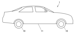
- FIG. 1A is an external view showing a vehicle having an electric brake system according to a first embodiment of the present invention.
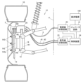
- FIG. 1B is a configuration diagram showing the periphery of one of a plurality of wheels of a vehicle.
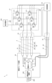
- 1 is a schematic diagram showing an example of the configuration of an electric brake device, an inverter circuit, and a switching circuit of an electric brake system.
- FIG. 3A is a side view showing the configuration of the power line cable.
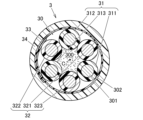
- FIG. 3B is a cross-sectional view of the power line cable taken along line AA in FIG. 3A.
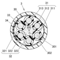
- FIG. 11 is a cross-sectional view of a power line cable according to a second embodiment.
- FIG. 11 is a cross-sectional view of an electric brake cable according to a third embodiment.
- Fig. 1A is an external view showing a vehicle 1 having an electric brake system 2 according to a first embodiment of the present invention.
- Fig. 1B is a configuration diagram showing the periphery of one of a plurality of wheels 10 of the vehicle 1.
- the electric brake system 2 is configured to include an electric brake device 20, an inverter circuit 21, a power line switching circuit 22, a signal line switching circuit 23, a control device 24 that controls the inverter circuit 21, the power line switching circuit 22, and the signal line switching circuit 23, a power line cable 3 that supplies three-phase AC current to the electric brake device 20, and a pair of signal line cables 41, 42 that transmit signals between the electric brake device 20 and the control device 24.
- the power line cable 3 is one aspect of an electric brake cable of the present invention.
- the electric brake device 20 is supported by the suspension device 12 together with the knuckle 13 and the hub unit 14 so as to be movable up and down relative to the vehicle body 11.
- the hub unit 14 has an outer ring 141 fixed to the knuckle 13 by a number of bolts 140, and a hub wheel 142 supported so as to be freely rotatable relative to the outer ring 141.
- a wheel mounting flange 142a is provided on the hub wheel 142, and the wheel 10 and brake rotor 15 are attached to this wheel mounting flange 142a by a number of hub bolts 143.
- the electric brake device 20 presses the brake pads 200 against the brake rotor 15 to generate frictional force and brake the wheel 10.
- the vehicle 1 is equipped with a DC power supply 100 that outputs a DC voltage to an inverter circuit 21, and the inverter circuit 21 generates a three-phase AC current by switching the DC voltage output from the DC power supply 100.
- the generated three-phase AC current is supplied to the electric brake device 20 via a power supply cable 3.
- FIG. 2 is a schematic diagram showing an example of the configuration of the electric brake device 20, inverter circuit 21, power supply line switching circuit 22, and signal line switching circuit 23 of the electric brake system 2.
- the electric brake device 20 has an electric motor 201 as a power source.
- the electric motor 201 is a three-phase AC motor having a U-phase winding, a V-phase winding, and a W-phase winding on the stator.
- the electric brake system 2 has one inverter circuit 21 and one electric motor 201 corresponding to one wheel 10.
- the electric brake device 20 also has a motion conversion mechanism 202 that converts the rotation of the electric motor 201 into linear motion of the brake pad 200.
- the motion conversion mechanism 202 is configured, for example, by a ball screw mechanism or a rack and pinion mechanism.
- the electric brake device 20 also has an angle sensor 203 that detects the rotation angle of the rotor relative to the stator of the electric motor 201, a load sensor 204 that detects the pressing reaction force of the brake rotor 15 acting on the brake pad 200, and a temperature sensor 205 that detects the temperature of the electric motor 201.
- the control device 24 controls the electric motor 201 based on the detection signals of these sensors.
- the inverter circuit 21 has six switching elements 211 connected in a three-phase bridge configuration, and freewheel diodes 212 connected in parallel to each switching element 211. Each switching element 211 is switched between an on state and an off state by a PWM (Pulse Width Modulation) signal from the control device 24.
- the control device 24 generates a three-phase AC current to be supplied to the electric motor 201 of the electric brake device 20 by PWM control based on the detection signal of the angle sensor 203.
- the power line switching circuit 22 is, for example, composed of a triple relay circuit.
- the control device 24 controls the power line switching circuit 22 to switch whether the three-phase AC current generated by the inverter circuit 21 is supplied to the electric motor 201 via a first group of wires 31 of the power line cable 3 described below, or via a second group of wires 32. Note that in this embodiment, the switching is performed on the inverter side, but it is also possible to switch on the caliper side. It is also possible to have a dual system without switching.
- the power supply cable 3 and the first and second signal cables 41, 42 are strung with a portion of their longitudinal lengths loose between the electric brake device 20 and the vehicle body 11 so that they can respond to the vertical movement of the wheels 10 relative to the vehicle body 11 and the twisting caused by steering.
- the detection signals of the angle sensor 203, the load sensor 204, and the temperature sensor 205 are transmitted to the control device 24 via one of the pair of signal cables 41, 42.
- the signal line switching circuit 23 can switch which of the pair of signal line cables 41, 42 is used to transmit the detection signals of the angle sensor 203, the load sensor 204, and the temperature sensor 205 to the control device 24.
- the signal line switching circuit 23 is configured, for example, by a relay circuit. In this embodiment, the signal line cables 41, 42 are thus made redundant.
- the control device 24 controls the signal line switching circuit 23 when an abnormality occurs in one of the signal line cables 41, and the detection signals of the angle sensor 203, the load sensor 204, and the temperature sensor 205 are transmitted to the control device 24 by the other signal line cable 42.
- the control device 24 detects that an abnormality has occurred in one of the signal line cables 41, for example, when the detection signals of any of the angle sensor 203, the load sensor 204, and the temperature sensor 205 are no longer being transmitted normally by the one signal line cable 41.
- FIG. 3A is a side view showing the configuration of the power cable 3.
- FIG. 3B is a cross-sectional view of the power cable 3 taken along line A-A in FIG. 3A.
- the power cable 3 comprises a twisted body 30 formed by twisting together a number of electric wires, a tape member 33 wrapped around the outer periphery of the twisted body 30, and a sheath 34 covering the outer periphery of the tape member 33.
- the twisted body 30 is formed by twisting together a first group of electric wires 31 and a second group of electric wires 32, and an interposer 300 made of a fibrous material such as staple fiber or Kevlar (registered trademark) is disposed in the center of the twisted body 30.
- the tape member 33 may be, for example, a strip-shaped member made of nonwoven fabric, paper, or resin.
- the sheath 34 is made of, for example, urethane resin.
- the first electric wire group 31 and the second electric wire group 32 are both redundantly connected to the electric motor 201.
- the first electric wire group 31 includes a first U-phase electric wire 311, a first V-phase electric wire 312, and a first W-phase electric wire 313.
- the second electric wire group 32 includes a second U-phase electric wire 321, a second V-phase electric wire 322, and a second W-phase electric wire 323.
- the first U-phase electric wire 311, the first V-phase electric wire 312, the first W-phase electric wire 313, the second U-phase electric wire 321, the second V-phase electric wire 322, and the second W-phase electric wire 323 are arranged side by side in the cable circumferential direction about the central axis C1 of the power supply cable 3.
- the first U-phase wire 311, the first V-phase wire 312, the first W-phase wire 313, the second U-phase wire 321, the second V-phase wire 322, and the second W-phase wire 323 each have a conductor 301 and an insulator 302 that covers the conductor 301.
- the conductor 301 is, for example, a twisted wire formed by twisting together a plurality of metal wires.
- this metal wire for example, a tin-plated copper wire, a tin-plated copper alloy wire, a silver-plated copper wire, or a silver-plated copper alloy wire can be suitably used.
- the insulator 302 is made of an insulating resin material such as fluororesin.
- the first U-phase wire 311, the first V-phase wire 312, the first W-phase wire 313, the second U-phase wire 321, the second V-phase wire 322, and the second W-phase wire 323 have the same conductor cross-sectional area, outer diameter, etc.
- each of these electric wires can be distinguished during terminal processing because the insulator 302 has a different color.
- the first U-phase wire 311, the first V-phase wire 312, and the first W-phase wire 313 are adjacent to each other in the cable circumferential direction
- the second U-phase wire 321, the second V-phase wire 322, and the second W-phase wire 323 are adjacent to each other in the cable circumferential direction. More specifically, the first U-phase wire 311, the first V-phase wire 312, the first W-phase wire 313, the second U-phase wire 321, the second V-phase wire 322, and the second W-phase wire 323 are lined up in this order in the cable circumferential direction.
- the switching circuit 22 can switch between supplying current to the electric motor 201 via the first group of electric wires 31 and supplying current to the electric motor 201 via the second group of electric wires 32.
- the first group of electric wires 31 is used as a regular system and the second group of electric wires 32 is used as a standby system, and when an abnormality occurs in the first group of electric wires 31 of the regular system, the system is switched to the second group of electric wires 32 of the standby system to supply three-phase AC current to the electric motor 201.
- the opposite may also be true, with the first group of electric wires 31 used as the standby system and the second group of electric wires 32 used as the regular system.
- the control device 24 determines that an abnormality such as a disconnection has occurred, and controls the switching circuit 22 to switch to a state in which current is supplied to the electric motor 201 through the second group of wires 32, which is the standby system.
- the control device 24 controls the switching circuit 22 to switch to the standby system, it also outputs a signal to notify the driver of the vehicle 1 of the occurrence of the abnormality.
- the first U-phase wire 311, the first V-phase wire 312, and the first W-phase wire 313 of the first wire group 31 and the second U-phase wire 321, the second V-phase wire 322, and the second W-phase wire 323 of the second wire group 32 are included in one power line cable 3, so the wiring man-hours can be reduced compared to when each wire of the first wire group 31 and each wire of the second wire group 32 are each formed as separate cables.
- the first U-phase wire 311, the first V-phase wire 312, and the first W-phase wire 313 are adjacent to each other in the circumferential direction of the cable
- the second U-phase wire 321, the second V-phase wire 322, and the second W-phase wire 323 are adjacent to each other in the circumferential direction of the cable.
- the signal line cables 41, 42 are made redundant. Therefore, even if one of the signal line cables 41 is broken or partially broken while it is being used as a regular system, the signal line switching circuit 23 is controlled to switch to the backup signal line cable 42, thereby making it possible to prevent the occurrence of a situation in which the electric brake device 20 cannot be properly controlled.
- Fig. 4 is a cross-sectional view of a power line cable 3 according to the second embodiment.
- a first U-phase electric wire 311, a first V-phase electric wire 312, a first W-phase electric wire 313, a second U-phase electric wire 321, a second V-phase electric wire 322, and a second W-phase electric wire 323 are arranged side by side in the circumferential direction, but the order of the electric wires is different from that in the first embodiment.
- any one of the first U-phase electric wire 311, the first V-phase electric wire 312, and the first W-phase electric wire 313 constituting the first electric wire group 31 and any one of the second U-phase electric wire 321, the second V-phase electric wire 322, and the second W-phase electric wire 323 constituting the second electric wire group 32 are alternately arranged along the cable circumferential direction.
- the first U-phase electric wire 311 is arranged between the second W-phase electric wire 323 and the second U-phase electric wire 321
- the first V-phase electric wire 312 is arranged between the second U-phase electric wire 321 and the second V-phase electric wire 322
- the first W-phase electric wire 313 is arranged between the second V-phase electric wire 322 and the second W-phase electric wire 323.
- the other configurations of the power line cable 3 and the electric brake system 2 in this embodiment are the same as those in the first embodiment, and a tape member 33 is wound around the outer periphery of a twisted body 30 formed by twisting together a first U-phase electric wire 311, a second U-phase electric wire 321, a first V-phase electric wire 312, a second V-phase electric wire 322, a first W-phase electric wire 313, and a second W-phase electric wire 323, and the outer periphery of the tape member 33 is covered by a sheath 34.
- one of the first electric wire group 31 and the second electric wire group 32 is used as a regular system, and the other is used as a standby system.
- this embodiment also makes it possible to prevent occurrence of a situation in which an appropriate current cannot be supplied to the electric brake device 20.
- the electric brake device 20 moves up and down together with the wheels 10 relative to the vehicle body 11, it is possible to prevent stress from concentrating on one of the first electric wire group 31 and the second electric wire group 32.
- the standby electric wires e.g., the second U-phase electric wire 321, the second V-phase electric wire 322, and the second W-phase electric wire 323 are interposed between the regular electric wires (e.g., the first U-phase electric wire 311, the first V-phase electric wire 312, and the first W-phase electric wire 313), the distance between the electric wires through which the current flows can be increased, suppressing temperature rise, allowing a larger current to flow, or making it possible to reduce the conductor cross-sectional area and outer diameter of each electric wire.
- Fig. 5 is a cross-sectional view of an electric brake cable 5 according to the third embodiment.
- the power supply cable 3 that supplies current to the electric motor 201 and the signal cable 41, 42 that transmits detection signals from the sensors are separate, but in the third embodiment, the electric wires of the power supply cable 3 and the signal cable 41, 42 are integrated into a single electric brake cable 5.
- the electric brake cable 5 has a first three-phase AC cable 51, a second three-phase AC cable 52, a plurality of signal line cables 53 to 55, and one twisted pair cable 56, and these cables are twisted together to form a twisted body 50.
- the first three-phase AC cable 51, the second three-phase AC cable 52, and the plurality of signal line cables 53 to 55 are arranged side by side in the cable circumferential direction centered on the central axis C2 of the electric brake cable 5.
- the twisted pair cable 56 has a pair of signal lines 561, and is arranged in the valley between the signal line cables 54 and 55.
- the electric brake cable 5 also includes a tape member 57 wrapped around the outer circumference of the twisted body 50, a sheath 58 that covers the outer circumference of the tape member 57, and an interposer 59 that is disposed around the twisted body 50.
- the materials of the tape member 57, the sheath 58, and the interposer 59 are the same as those in the first embodiment.
- the first three-phase AC cable 51 has a first wire group 510 including a first U-phase wire 511, a first V-phase wire 512, and a first W-phase wire 513, and a first shield conductor 514, and the first U-phase wire 511, the first V-phase wire 512, and the first W-phase wire 513 are twisted together and covered by the first shield conductor 514.
- the second three-phase AC cable 52 has a second wire group 520 including a second U-phase wire 521, a second V-phase wire 522, and a second W-phase wire 523, and a second shield conductor 524, and the second U-phase wire 521, the second V-phase wire 522, and the second W-phase wire 523 are twisted together and covered by the second shield conductor 524.
- the first U-phase wire 511, the first V-phase wire 512, and the first W-phase wire 513, as well as the second U-phase wire 521, the second V-phase wire 522, and the second W-phase wire 523, have a conductor 501 and an insulator 502 that covers the conductor 501, as in the first embodiment.
- the conductor 501 is, for example, a twisted wire made by twisting together multiple metal wires
- the insulator 502 is made of an insulating resin material such as fluororesin.
- the first shield conductor 514 and the second shield conductor 524 are, for example, braided shields made by braiding multiple shield wires in a lattice pattern.
- Each of the signal line cables 53 to 55 is constructed by twisting together a number of shielded twisted pair wires 6.
- each of the signal line cables 53 to 55 has three shielded twisted pair wires 6.
- Each of the shielded twisted pair wires 6 has a pair of twisted signal wires 61, 61 and a shield conductor 62 that covers the pair of signal wires 61, 61.
- the pair of signal lines 61, 61 each have a signal line conductor 611 and an insulator 612 that covers the signal line conductor 611.
- the signal line conductor 611 is, for example, a twisted wire made by twisting together multiple metal wires
- the insulator 612 is made of an insulating resin material such as fluororesin.
- the shield conductor 62 is, for example, a braided shield made by braiding multiple shield wires in a lattice pattern.
- the signal line cables 53 to 55 are referred to as the first signal line cable 53, the second signal line cable 54, and the third signal line cable 55, respectively.
- the first signal line cable 53 transmits a detection signal from the load sensor 204.
- the second signal line cable 54 and the third signal line cable 55 transmit a detection signal from the angle sensor 203.
- the twisted pair cable 56 transmits a detection signal from the temperature sensor 205.
- the first signal line cable 53 includes a total of six signal lines 61, of which half (three signal lines 61) are used as a regular system, and the remaining three signal lines 61 are used as a spare system.
- the second signal line cable 54 and the third signal line cable 55 include a total of 12 signal lines 61, of which half (six signal lines 61) are used as a regular system, and the remaining six signal lines 61 are used as a spare system.
- the twisted pair cable 56 has a pair of signal lines 561, one of which is used as a regular system, and the other is used as a spare system. As in the first embodiment, these signal lines are switched between the regular system and the spare system by a signal line switching circuit formed, for example, by a relay circuit.
- the first three-phase AC cable 51 and the second three-phase AC cable 52 are not adjacent to each other in the circumferential direction of the cables.
- the first three-phase AC cable 51 and the second three-phase AC cable 52 are shown side by side in the left-right direction of the drawing, with the first signal line cable 53 being arranged on the upper side of the drawing between the first three-phase AC cable 51 and the second three-phase AC cable 52, and the second signal line cable 54 and the third signal line cable 55 being arranged on the lower side of the drawing between the first three-phase AC cable 51 and the second three-phase AC cable 52.
- at least one signal line cable of the first to third signal line cables 53 to 55 is interposed between the first three-phase AC cable 51 and the second three-phase AC cable 52.
- the first wire group 510 of the first three-phase AC cable 51 and the second wire group 520 of the second three-phase AC cable 52 are both redundantly connected to the electric motor 201 of the electric brake device 20, and as in the first embodiment, one is used as a regular system and the other is used as a backup system, and are switched by a power line switching circuit constituted by, for example, a relay circuit.
- three-phase AC current is supplied to the electric motor 201 by the first U-phase wire 511, the first V-phase wire 512, and the first W-phase wire 513 of the first wire group 510, and when an abnormality occurs in the first wire group 510, three-phase AC current is supplied to the electric motor 201 by the second U-phase wire 521, the second V-phase wire 522, and the second W-phase wire 523 of the second wire group 520.
- the first three-phase AC cable 51 is configured by collectively covering the first U-phase electric wire 511, the first V-phase electric wire 512, and the first W-phase electric wire 513 of the first electric wire group 510 with the first shield conductor 514
- the second three-phase AC cable 52 is configured by collectively covering the second U-phase electric wire 521, the second V-phase electric wire 522, and the second W-phase electric wire 523 of the second electric wire group 520 with the second shield conductor 524.
- each pair of signal lines 61 of the first to third signal line cables 53 to 55 is covered with a shield conductor 63, which suppresses crosstalk between the multiple shielded twisted pair wires 6 and also suppresses the effects of radiation noise caused by the current supplied to the electric motor 201.
- the first three-phase AC cable 51 is arranged between the first signal line cable 53 and the second signal line cable 54 in the cable circumferential direction
- the second three-phase AC cable 52 is arranged between the first signal line cable 53 and the third signal line cable 55, so that crosstalk between the first signal line cable 53 and the second signal line cable 54 and the third signal line cable 55 is suppressed.
- An electric brake cable (3, 5) for supplying three-phase AC current to an electric motor (201) of an electric brake device (2) using an electric motor (201) as a power source, the electric brake cable (3, 5) comprising a first wire group (31, 510) including a first U-phase wire (311, 511), a first V-phase wire (312, 512), and a first W-phase wire (313, 513), and a second wire group (31, 510) including a second U-phase wire (321, 521), a second V-phase wire (322, 522), and a second W-phase wire (323, 523).
- An electric brake cable (3, 5) comprising a wire group (32, 520), a tape member (33, 57) wound around the outer circumference of a stranded body (30, 50) formed by stranding the first electric wire group (31, 510) and the second electric wire group (32, 520), and a sheath (34, 58) covering the outer circumference of the tape member (33, 57), in which the first electric wire group (31, 510) and the second electric wire group (32, 520) are both redundantly connected to the electric motor (201).
- the electric brake cable according to the present invention makes it possible to prevent the occurrence of a situation in which it becomes impossible to supply current to the electric brake device, particularly in vehicles such as electric vehicles and so-called hybrid vehicles.
- Electric brake system 20 Electric brake device 201... Electric motor 22... Switching circuit 3... Power line cable (cable for electric brake) 30... Twisted body 31... First group of electric wires 311... First U-phase electric wire 312... First V-phase electric wire 313... First W-phase electric wire 32... Second group of electric wires 321... Second U-phase electric wire 322... Second V-phase electric wire 323... Second W-phase electric wire 33... Tape member 34... Sheath 5... Electric brake cable 50... Twisted body 51... First three-phase AC cable 510... First group of electric wires 511... First U-phase electric wire 512... First V-phase electric wire 513... First W-phase electric wire 514... First shield conductor 52... Second three-phase AC cable 520...
Landscapes
- Engineering & Computer Science (AREA)
- Transportation (AREA)
- Mechanical Engineering (AREA)
- Braking Systems And Boosters (AREA)
- Valves And Accessory Devices For Braking Systems (AREA)
Abstract
Description
図1Aは、本発明の第1の実施の形態に係る電動ブレーキシステム2を有する車両1を示す外観図である。図1Bは、車両1の複数の車輪10のうち一つの車輪10の周辺部を示す構成図である。電動ブレーキシステム2は、電動ブレーキ装置20と、インバータ回路21と、電源線切替回路22及び信号線切替回路23と、インバータ回路21ならびに電源線切替回路22及び信号線切替回路23を制御する制御装置24と、電動ブレーキ装置20に三相交流電流を供給する電源線ケーブル3と、電動ブレーキ装置20と制御装置24との間で信号を伝送する一対の信号線ケーブル41,42と、を有して構成されている。電源線ケーブル3は、本発明の電動ブレーキ用ケーブルの一態様である。
以上説明した第1の実施の形態によれば、第1電線群31の第1U相電線311、第1V相電線312、及び第1W相電線313の何れかに例えば断線や半断線が発生した場合でも、第2電線群32の第2U相電線321、第2V相電線322、及び第2W相電線323によって電動モータ201に電流を供給することができる。これにより、電動ブレーキ装置20に適切な電流を供給できなくなる事態の発生を抑制することが可能となる。
次に、本発明の第2の実施の形態について、図4を参照して説明する。図4は、第2の実施の形態に係る電源線ケーブル3の断面図である。本実施の形態では、第1の実施の形態と同様に、第1U相電線311、第1V相電線312、第1W相電線313、第2U相電線321、第2V相電線322、及び第2W相電線323が周方向に並んで配置されているが、その順序が第1の実施の形態と異なっている。
次に、本発明の第3の実施の形態について、図5を参照して説明する。図5は、第3の実施の形態に係る電動ブレーキ用ケーブル5の断面図である。第1の実施の形態では、電動モータ201に電流を供給する電源線ケーブル3と各センサの検出信号を伝送する信号線ケーブル41,42が分かれていたが、第3の実施の形態では、電源線ケーブル3の各電線と信号線ケーブル41,42の各電線とが1本の電動ブレーキ用ケーブル5に集約されている。
次に、以上説明した第1乃至第3の実施の形態から把握される技術思想について、各実施の形態における符号等を援用して記載する。ただし、以下の記載における各符号は、特許請求の範囲における構成要素を実施の形態に具体的に示した部材等に限定するものではない。
201…電動モータ 22…切替回路
3…電源線ケーブル(電動ブレーキ用ケーブル) 30…撚合体
31…第1電線群 311…第1U相電線
312…第1V相電線 313…第1W相電線
32…第2電線群 321…第2U相電線
322…第2V相電線 323…第2W相電線
33…テープ部材 34…シース
5…電動ブレーキ用ケーブル 50…撚合体
51…第1三相交流ケーブル 510…第1電線群
511…第1U相電線 512…第1V相電線
513…第1W相電線 514…第1シールド導体
52…第2三相交流ケーブル 520…第2電線群
521…第2U相電線 522…第2V相電線
523…第2W相電線 524…第2シールド導体
53~55…信号線ケーブル 57…テープ部材
58…シース 61…信号線
Claims (7)
- 電動モータを動力源とする電動ブレーキ装置の前記電動モータに三相交流電流を供給する電動ブレーキ用ケーブルであって、
第1U相電線、第1V相電線、及び第1W相電線を備えた第1電線群と、
第2U相電線、第2V相電線、及び第2W相電線を備えた第2電線群と、
前記第1電線群及び前記第2電線群を撚り合わせた撚合体の外周に巻き付けられたテープ部材と、
前記テープ部材の外周を被覆するシースと、を備え、
前記第1電線群及び前記第2電線群が共に前記電動モータに冗長的に接続されている、
電動ブレーキ用ケーブル。 - 前記第1U相電線、前記第1V相電線、前記第1W相電線、前記第2U相電線、前記第2V相電線、及び前記第2W相電線がケーブル周方向に並んで配置されており、
前記第1U相電線、前記第1V相電線、及び前記第1W相電線が前記ケーブル周方向に互いに隣り合い、
前記第2U相電線、前記第2V相電線、及び前記第2W相電線が前記ケーブル周方向に互いに隣り合っている、
請求項1に記載の電動ブレーキ用ケーブル。 - 前記第1U相電線、前記第1V相電線、前記第1W相電線、前記第2U相電線、前記第2V相電線、及び前記第2W相電線がケーブル周方向に並んで配置されており、
前記第1電線群を構成する前記第1U相電線、前記第1V相電線、前記第1W相電線の何れかの電線と、前記第2電線群を構成する前記第2U相電線、前記第2V相電線、前記第2W相電線の何れかの電線とが、前記ケーブル周方向に沿って交互に配置されている、
請求項1に記載の電動ブレーキ用ケーブル。 - 前記第1U相電線、前記第1V相電線、前記第1W相電線が撚り合わされた状態で第1シールド導体に覆われた第1三相交流ケーブルと、
前記第2U相電線、前記第2V相電線、前記第2W相電線が撚り合わされた状態で第2シールド導体に覆われた第2三相交流ケーブルと、を有する、
請求項1に記載の電動ブレーキ用ケーブル。 - 前記撚合体は、前記第1三相交流ケーブルと、前記第2三相交流ケーブルと、複数の信号線とを有し、
前記複数の信号線が冗長化されている、
請求項4に記載の電動ブレーキ用ケーブル。 - 前記複数の信号線が撚り合わされて信号線ケーブルを構成し、
前記信号線ケーブルと、前記第1三相交流ケーブルと、前記第2三相交流ケーブルと、が撚り合わされて前記撚合体を構成している、
請求項5に記載の電動ブレーキ用ケーブル。 - 複数の前記信号線ケーブル、前記第1三相交流ケーブル、及び前記第2三相交流ケーブルがケーブル周方向に並んで配置されており、
前記ケーブル周方向において、前記第1三相交流ケーブルと前記第2三相交流ケーブルとの間に少なくとも1本の前記信号線ケーブルが介在している、
請求項6に記載の電動ブレーキ用ケーブル。
Priority Applications (1)
| Application Number | Priority Date | Filing Date | Title |
|---|---|---|---|
| CN202480015298.5A CN120916926A (zh) | 2023-03-10 | 2024-03-04 | 电动制动器用电缆 |
Applications Claiming Priority (2)
| Application Number | Priority Date | Filing Date | Title |
|---|---|---|---|
| JP2023037447A JP7867460B2 (ja) | 2023-03-10 | 2023-03-10 | 電動ブレーキ用ケーブル |
| JP2023-037447 | 2023-03-10 |
Publications (1)
| Publication Number | Publication Date |
|---|---|
| WO2024190503A1 true WO2024190503A1 (ja) | 2024-09-19 |
Family
ID=92755593
Family Applications (1)
| Application Number | Title | Priority Date | Filing Date |
|---|---|---|---|
| PCT/JP2024/008085 Ceased WO2024190503A1 (ja) | 2023-03-10 | 2024-03-04 | 電動ブレーキ用ケーブル |
Country Status (3)
| Country | Link |
|---|---|
| JP (1) | JP7867460B2 (ja) |
| CN (1) | CN120916926A (ja) |
| WO (1) | WO2024190503A1 (ja) |
Citations (6)
| Publication number | Priority date | Publication date | Assignee | Title |
|---|---|---|---|---|
| JP2005096680A (ja) * | 2003-09-26 | 2005-04-14 | Tokico Ltd | 電動ブレーキ装置 |
| JP2008184904A (ja) * | 2007-01-26 | 2008-08-14 | Shimadzu Corp | 真空ポンプ装置 |
| JP2009095090A (ja) * | 2007-10-04 | 2009-04-30 | Canon Inc | 位置決め装置、露光装置及びデバイス製造方法 |
| WO2017046847A1 (ja) * | 2015-09-14 | 2017-03-23 | 日立金属株式会社 | 複合ケーブル及び複合ハーネス |
| JP2017525119A (ja) * | 2014-08-11 | 2017-08-31 | スチューダー,クリストフ | 電気ケーブル |
| JP2018030463A (ja) * | 2016-08-25 | 2018-03-01 | 日立オートモティブシステムズ株式会社 | 電動ブレーキ装置、および、コントローラ |
-
2023
- 2023-03-10 JP JP2023037447A patent/JP7867460B2/ja active Active
-
2024
- 2024-03-04 WO PCT/JP2024/008085 patent/WO2024190503A1/ja not_active Ceased
- 2024-03-04 CN CN202480015298.5A patent/CN120916926A/zh active Pending
Patent Citations (6)
| Publication number | Priority date | Publication date | Assignee | Title |
|---|---|---|---|---|
| JP2005096680A (ja) * | 2003-09-26 | 2005-04-14 | Tokico Ltd | 電動ブレーキ装置 |
| JP2008184904A (ja) * | 2007-01-26 | 2008-08-14 | Shimadzu Corp | 真空ポンプ装置 |
| JP2009095090A (ja) * | 2007-10-04 | 2009-04-30 | Canon Inc | 位置決め装置、露光装置及びデバイス製造方法 |
| JP2017525119A (ja) * | 2014-08-11 | 2017-08-31 | スチューダー,クリストフ | 電気ケーブル |
| WO2017046847A1 (ja) * | 2015-09-14 | 2017-03-23 | 日立金属株式会社 | 複合ケーブル及び複合ハーネス |
| JP2018030463A (ja) * | 2016-08-25 | 2018-03-01 | 日立オートモティブシステムズ株式会社 | 電動ブレーキ装置、および、コントローラ |
Also Published As
| Publication number | Publication date |
|---|---|
| JP7867460B2 (ja) | 2026-05-29 |
| JP2024128461A (ja) | 2024-09-24 |
| CN120916926A (zh) | 2025-11-07 |
Similar Documents
| Publication | Publication Date | Title |
|---|---|---|
| US10741306B2 (en) | Composite cable | |
| JP6493707B2 (ja) | 複合ケーブル、複合ハーネス、及び車両 | |
| JP7158467B2 (ja) | アーキテクチャ | |
| JP6424950B2 (ja) | 複合ケーブル、複合ハーネス、及び車両 | |
| JP7279422B2 (ja) | 複合ケーブル及び複合ハーネス | |
| JP2023048883A (ja) | 複合ケーブル | |
| JP7318508B2 (ja) | ケーブル及びハーネス | |
| JP6493708B2 (ja) | 複合ケーブル、複合ハーネス、及び車両 | |
| US11152136B2 (en) | Composite cable | |
| JP2024128461A (ja) | 電動ブレーキ用ケーブル | |
| JP6876259B2 (ja) | 複合ケーブル、複合ハーネス、及び車両 | |
| JP7192455B2 (ja) | 複合ケーブル及び複合ハーネス | |
| JP7525006B2 (ja) | 複合ケーブル、及び複合ハーネス | |
| US20250104886A1 (en) | Composite cable and composite harness | |
| JP2025047208A (ja) | 複合ケーブル及び複合ハーネス | |
| JP2018200894A (ja) | 複合ケーブル、複合ハーネス、及び車両 | |
| US20250104889A1 (en) | Composite cable and composite harness | |
| WO2018037612A1 (ja) | 電動ブレーキ装置、および、コントローラ | |
| JP2025007287A (ja) | 車両用配線構造及び車両 | |
| JP2025162726A (ja) | 複合ケーブル | |
| JP2020080334A (ja) | 自動車用複合ケーブル | |
| JP2020004732A (ja) | 複合ハーネス | |
| JP2019106386A (ja) | 複合ハーネス | |
| JP2016197564A (ja) | ケーブル構造 |
Legal Events
| Date | Code | Title | Description |
|---|---|---|---|
| 121 | Ep: the epo has been informed by wipo that ep was designated in this application |
Ref document number: 24770614 Country of ref document: EP Kind code of ref document: A1 |
|
| WWE | Wipo information: entry into national phase |
Ref document number: CN2024800152985 Country of ref document: CN Ref document number: 202480015298.5 Country of ref document: CN |
|
| NENP | Non-entry into the national phase |
Ref country code: DE |
|
| WWP | Wipo information: published in national office |
Ref document number: 202480015298.5 Country of ref document: CN |
|
| 122 | Ep: pct application non-entry in european phase |
Ref document number: 24770614 Country of ref document: EP Kind code of ref document: A1 |