WO2024190303A1 - コンデンサ - Google Patents
コンデンサ Download PDFInfo
- Publication number
- WO2024190303A1 WO2024190303A1 PCT/JP2024/005846 JP2024005846W WO2024190303A1 WO 2024190303 A1 WO2024190303 A1 WO 2024190303A1 JP 2024005846 W JP2024005846 W JP 2024005846W WO 2024190303 A1 WO2024190303 A1 WO 2024190303A1
- Authority
- WO
- WIPO (PCT)
- Prior art keywords
- hole
- exterior member
- terminal
- metal
- exterior
- Prior art date
- Legal status (The legal status is an assumption and is not a legal conclusion. Google has not performed a legal analysis and makes no representation as to the accuracy of the status listed.)
- Ceased
Links
Images


Classifications
-
- H—ELECTRICITY
- H01—ELECTRIC ELEMENTS
- H01G—CAPACITORS; CAPACITORS, RECTIFIERS, DETECTORS, SWITCHING DEVICES, LIGHT-SENSITIVE OR TEMPERATURE-SENSITIVE DEVICES OF THE ELECTROLYTIC TYPE
- H01G2/00—Details of capacitors not covered by a single one of groups H01G4/00-H01G11/00
- H01G2/10—Housing; Encapsulation
-
- H—ELECTRICITY
- H01—ELECTRIC ELEMENTS
- H01G—CAPACITORS; CAPACITORS, RECTIFIERS, DETECTORS, SWITCHING DEVICES, LIGHT-SENSITIVE OR TEMPERATURE-SENSITIVE DEVICES OF THE ELECTROLYTIC TYPE
- H01G4/00—Fixed capacitors; Processes of their manufacture
- H01G4/002—Details
- H01G4/224—Housing; Encapsulation
-
- H—ELECTRICITY
- H01—ELECTRIC ELEMENTS
- H01G—CAPACITORS; CAPACITORS, RECTIFIERS, DETECTORS, SWITCHING DEVICES, LIGHT-SENSITIVE OR TEMPERATURE-SENSITIVE DEVICES OF THE ELECTROLYTIC TYPE
- H01G4/00—Fixed capacitors; Processes of their manufacture
- H01G4/002—Details
- H01G4/228—Terminals
-
- H—ELECTRICITY
- H01—ELECTRIC ELEMENTS
- H01G—CAPACITORS; CAPACITORS, RECTIFIERS, DETECTORS, SWITCHING DEVICES, LIGHT-SENSITIVE OR TEMPERATURE-SENSITIVE DEVICES OF THE ELECTROLYTIC TYPE
- H01G4/00—Fixed capacitors; Processes of their manufacture
- H01G4/002—Details
- H01G4/228—Terminals
- H01G4/236—Terminals leading through the housing, i.e. lead-through
-
- H—ELECTRICITY
- H01—ELECTRIC ELEMENTS
- H01G—CAPACITORS; CAPACITORS, RECTIFIERS, DETECTORS, SWITCHING DEVICES, LIGHT-SENSITIVE OR TEMPERATURE-SENSITIVE DEVICES OF THE ELECTROLYTIC TYPE
- H01G4/00—Fixed capacitors; Processes of their manufacture
- H01G4/32—Wound capacitors
Definitions
- the present invention relates to a capacitor.
- Patent Document 1 describes a capacitor that includes a capacitor element having a first electrode on one end face and a second electrode on the other end face, and a resin exterior body that covers the entire capacitor element, the exterior body including a first exterior body that covers the first electrode side of the capacitor element and a second exterior body that covers the second electrode side of the capacitor element, and the first exterior body and the second exterior body are joined so that the inside of the exterior body is airtight.
- the capacitor according to the main aspect of the present invention comprises a capacitor element having electrodes, a resin exterior case that covers the capacitor element in a hermetically sealed state, a thin metal body that is embedded in the exterior case and surrounds the entire capacitor element, and a metal terminal that is connected to the electrodes and extends through the exterior case to the outside.
- the exterior case is provided with a first through hole through which the metal terminal passes
- the metal body is provided with a second through hole that is aligned with the first through hole and is larger than the first through hole.
- the metal terminal includes a first overlapping portion that contacts the inner wall surface surrounding the first through hole in the exterior case. The first overlapping portion overlaps the entire second through hole in the direction in which the metal terminal passes through the exterior case.
- the present invention provides a capacitor that can improve the moisture resistance of the capacitor element.
- FIG. 1 is a perspective view of a capacitor according to a first embodiment.
- FIG. 2 is an exploded perspective view of the capacitor according to the first embodiment.
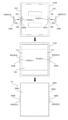
- FIG. 3A is a front cross-sectional view of a capacitor in accordance with embodiment 1.
- FIG. 3B is a side cross-sectional view of the capacitor in accordance with the first embodiment.
- FIG. 4A is a plan view of a first exterior member according to the first embodiment.
- FIG. FIG. 4B is a perspective view of the second exterior member according to the first embodiment, as viewed from below.
- FIG. 5 is an exploded perspective view of the metal body according to the first embodiment.
- FIG. 6 is a diagram for explaining an assembly procedure of the capacitor according to the first embodiment.
- FIG. 7 is a perspective view of a capacitor according to the second embodiment.
- FIG. 8 is an exploded perspective view of a capacitor according to the second embodiment.
- FIG. 9A is a front cross-sectional view of a capacitor according to a second embodiment.
- FIG. 9B is a side cross-sectional view of the capacitor according to the second embodiment.
- FIG. 10A is a plan view of a first exterior member according to the second embodiment.
- FIG. 10B is a perspective view of the second exterior member according to the second embodiment, as viewed from below.
- FIG. 11A is an exploded perspective view of a metal body according to the second embodiment.
- FIG. 11B is a perspective view of a metal body according to the second embodiment.
- FIG. 12 is a diagram for explaining an assembly procedure of the capacitor according to the second embodiment.
- FIG. 13A is a front cross-sectional view of a capacitor according to a first modified example.
- FIG. 13B is a side cross-sectional view of the capacitor according to the first modification.
- FIG. 14A is a side cross-sectional view of a front portion of a capacitor according to a second modification.
- FIG. 14B is a side cross-sectional view of the front portion of the capacitor according to the third modification.
- FIG. 14C is a side cross-sectional view of the front portion of the capacitor according to the fourth modification.
- FIG. 15A is a front view of a second exterior member according to a fifth modified example.
- FIG. 15B is a front view of the second exterior member according to Modification Example 5.
- FIG. 16A is a diagram for explaining a capacitor according to the sixth modified example.
- FIG. 16A is a diagram for explaining a capacitor according to the sixth modified example.
- FIG. 16B is a diagram for explaining a capacitor according to the sixth modification.
- FIG. 16C is a diagram for explaining a capacitor according to the sixth modification.
- FIG. 17A is a diagram for explaining a capacitor according to the sixth modification.
- FIG. 17B is a diagram for explaining a capacitor according to the sixth modification.
- Resin materials have moisture permeability, although the degree of permeability varies depending on the type. For this reason, there is concern that the above-mentioned capacitor, in which the capacitor element is covered with a resin exterior body, may not be able to sufficiently suppress moisture absorption by the capacitor element depending on the usage environment.
- the present invention provides a capacitor that can improve the moisture resistance of the capacitor element.
- Fig. 1 is a perspective view of a capacitor 1A according to the first embodiment.
- Fig. 2 is an exploded perspective view of the capacitor 1A according to the first embodiment.
- Fig. 3A is a front cross-sectional view of the capacitor 1A according to the first embodiment, and
- Fig. 3B is a side cross-sectional view of the capacitor 1A according to the first embodiment.
- Fig. 4A is a plan view of a first exterior member 210A according to the first embodiment.
- Fig. 4B is a perspective view of a second exterior member 220A according to the first embodiment, as viewed from below.
- Fig. 5 is an exploded perspective view of a metal body 300A according to the first embodiment.
- Capacitor 1A includes a capacitor element 100, an exterior case 200A, a metal body 300A, and a pair of metal terminals 400A.
- Capacitor element 100 is a film capacitor element, and is formed into a shape similar to a flat, oval cylinder by stacking two metallized films, each of which has aluminum vapor-deposited on a dielectric film, and then rolling or laminating the stacked metallized films and pressing them together.
- Capacitor element 100 has a pair of end faces 101 and a peripheral surface 102. Electrodes 110 are formed on both end faces 101 of capacitor element 100 by spraying a metal such as zinc.
- the capacitor element 100 may be formed from a metallized film in which aluminum is vapor-deposited onto a dielectric film, or may be formed from a metallized film in which other metals such as zinc or magnesium are vapor-deposited.
- the capacitor element 100 may be formed from a metallized film in which multiple of these metals are vapor-deposited, or from a metallized film in which an alloy of these metals is vapor-deposited.
- the exterior case 200A is made of a resin material with excellent moisture resistance and heat resistance, such as polyphenylene sulfide (PPS), and covers the capacitor element 100 in a sealed (airtight) state.
- the exterior case 200A has a rectangular parallelepiped shape and is formed by joining a first exterior member 210A and a second exterior member 220A.
- the first exterior member 210A has a rectangular box shape with an open top, and includes a rectangular plate-shaped bottom wall portion 211, and a rectangular plate-shaped front wall portion 212, rear wall portion 213, left wall portion 214, and right wall portion 215 rising from the outer periphery of the bottom wall portion 211.
- the front wall portion 212, rear wall portion 213, left wall portion 214, and right wall portion 215 form a rectangular cylindrical peripheral wall portion 216.
- the peripheral wall portion 216 has an open upper end (one end) and a closed lower end (the other end) by the bottom wall portion 211, surrounding the capacitor element 100.
- the front wall portion 212 faces the front electrode 110 of the capacitor element 100
- the rear wall portion 213 faces the rear electrode 110 of the capacitor element 100.
- the second exterior member 220A includes a top wall portion 221 having a rectangular plate shape, and covers the opening on the top surface of the first exterior member 210A.
- the exterior case 200A has a rectangular first through hole 230 provided at the center of the front wall portion 212 and the center of the rear wall portion 213 of the first exterior member 210A.
- the first through hole 230 penetrates the front wall portion 212 and the rear wall portion 213 in the front-rear direction.
- two square-shaped protrusions 241 are provided on each of the inner wall surfaces of the bottom wall portion 211, left side wall portion 214, and right side wall portion 215 of the first exterior member 210A.
- two square-shaped protrusions 242 are provided on the inner wall surface of the top wall portion 221 of the second exterior member 220A. These protrusions 241, 242 contact the peripheral surface 102 of the capacitor element 100. This fixes the capacitor element 100 in the up-down, left-right, and right-handed directions within the exterior case 200A.
- the metal body 300A is thin and embedded in the exterior case 200A, surrounding the entire capacitor element 100 in all directions, including top and bottom, front and back, and left and right.
- the metal body 300A is a metal plate made of, for example, copper or aluminum.
- the thickness of the metal body 300A can be, for example, about 0.8 mm.
- capacitor 1A the entire capacitor element 100 is surrounded by metal body 300A, which has lower moisture permeability than resin, making it easier to prevent moisture from entering exterior case 200A.
- the metal body 300A includes a first metal body 310A embedded in the first exterior member 210A and a second metal body 320A embedded in the second exterior member 220A.
- the first metal body 310A and the second metal body 320A are embedded in the first exterior member 210A and the second exterior member 220A, respectively, by insert molding.
- the first metal body 310A has a rectangular box shape with an open top so that its shape corresponds to the shape of the first exterior member 210A, and includes a rectangular plate-shaped bottom portion 311, a front side portion 312, a rear side portion 313, a left side portion 314, and a right side portion 315.
- the front side portion 312, the rear side portion 313, the left side portion 314, and the right side portion 315 form a peripheral portion 316 that surrounds the bottom portion 311.
- the bottom portion 311 of the first metal body 310A is embedded in almost the entire bottom wall portion 211 of the first exterior member 210A, and the peripheral portion 316 of the first metal body 310A is embedded in almost the entire peripheral wall portion 216 of the first exterior member 210A.
- the second metal body 320A has a rectangular top surface 321 that corresponds to the shape of the second exterior member 220A.
- the top surface 321 is embedded in almost the entire top wall 221 of the second exterior member 220A.
- the upper end of the first metal body 310A is provided with a rectangular frame-shaped folded portion 316a, in which the upper end of the peripheral portion 316 is folded inward at a right angle.
- the folded portion 316a is close to the upper end surface (peripheral surface of the top opening) of the peripheral wall portion 216 of the first exterior member 210A and faces the top surface portion 321 of the second metal body 320A.
- the folded portion 316a faces the outer periphery of the top surface portion 321 of the second metal body 320A in the vertical direction (the joining direction in which the first exterior member 210A and the second exterior member 220A are joined) (see Figures 3A and 3B).
- the path through which external moisture penetrates the resin portion between the first metal body 310A and the second metal body 320A in the exterior case 200A and reaches the interior of the exterior case 200A can be lengthened, and the intrusion of moisture into the exterior case 200A can be suppressed.
- the metal body 300A has a square-shaped second through hole 330 that matches the first through hole 230 at the center of the front side surface portion 312 and the center of the rear side surface portion 313 of the first metal body 310A.
- the diameter of the second through hole 330 is larger than the diameter of the first through hole 230.
- the metal body 300A is not present in the portion of the front side wall portion 212 between the inner peripheral edge of the first through hole 230 and the inner peripheral edge of the second through hole 330, and the metal body 300A is not present in the portion of the rear side wall portion 213 between the inner peripheral edge of the first through hole 230 and the inner peripheral edge of the second through hole 330.
- Each metal terminal 400A is formed of a conductive metal material such as copper, and includes an electrode terminal portion 410, a connection terminal portion 420, and a connection portion 430 that connects the electrode terminal portion 410 and the connection terminal portion 420.
- the electrode terminal portion 410 is formed in a disk shape.
- the electrode terminal portion 410 has a contact surface 411 that contacts the electrode 110 of the capacitor element 100, and the outer peripheral edge portion of the contact surface 411 is an arc surface without corners.
- the connection terminal portion 420 is formed in a disk shape and has a connection surface 421 to which an external terminal is connected.
- the connection portion 430 has a rectangular parallelepiped shape and is composed of a tube portion 431 and a shaft portion 432 that is fitted into the tube portion 431.
- the tube portion 431 protrudes from the surface opposite the contact surface 411 of the electrode terminal portion 410, and the shaft portion 432 protrudes from the surface opposite the connection surface 421 of the connection terminal portion 420.
- the electrode terminal portion 410 and the tube portion 431 are included in the first terminal portion 400a, and the connection terminal portion 420 and the shaft portion 432 are included in the second terminal portion 400b, which is provided separately from the first terminal portion 400a.
- the metal terminal 400A is configured by joining the first terminal portion 400a and the second terminal portion 400b together with the front wall portion 212 of the exterior case 200A in between, and is disposed on the side wall portion 212.
- the metal terminal 400A is configured by joining the first terminal portion 400a and the second terminal portion 400b together with the rear wall portion 213 of the exterior case 200A in between, and is disposed on the side wall portion 213.
- connection part 430 of the metal terminal 400A penetrates the first through hole 230 by joining the tube part 431 and the shaft part 432 at the first through hole 230.
- the outer peripheral surface of the connection part 430 and the inner peripheral surface of the first through hole 230 are in close contact with each other, and no gap is created between them.
- the second through hole 330 of the metal body 300A is made larger than the first through hole 230, ensuring insulation between the connection part 430 of the metal terminal 400A that passes through the first through hole 230 and the first metal body 310A.
- the distance between the two electrode terminal portions 410 is set to be slightly smaller than the dimension of the capacitor element 100 in the direction in which the two electrodes 110 are aligned, and the capacitor element 100 is press-fit between the two electrode terminal portions 410.
- a pressing force is applied from the electrode 110 of the capacitor element 100 to the electrode terminal portion 410, so that the electrode terminal portion 410 is in firm contact with the electrode 110.
- the outer peripheral edge portion of the electrode terminal portion 410 forms an arc surface. Therefore, the electrode 110 is less likely to be damaged when pressed in.
- the pressing force from the electrode 110 acts on the exterior case 200A via the electrode terminal portion 410.
- the joining direction between the first exterior member 210A and the second exterior member 220A is perpendicular to the penetration direction, so the pressing force does not act in a direction that separates the first exterior member 210A and the second exterior member 220A.
- the electrode terminal portion 410 of the metal terminal 400A functions as the first overlap portion OL1 and contacts the inner wall surface around the first through hole 230 in the exterior case 200A (front wall portion 212, rear wall portion 213). Also, when viewed from the penetration direction (front-to-rear direction), the electrode terminal portion 410 of the metal terminal 400A overlaps the entire second through hole 330 and overlaps the peripheral portion of the second through hole 330 in the metal body 300A (front side portion 312, rear side portion 313).
- connection terminal portion 420 of the metal terminal 400A functions as the second overlap portion OL2 and contacts the outer wall surface surrounding the first through hole 230 in the exterior case 200A.
- the connection terminal portion 420 of the metal terminal 400A overlaps the entire second through hole 330 and also overlaps the peripheral portion of the second through hole 330 in the metal body 300A.
- FIG. 6 is a diagram for explaining the assembly procedure for capacitor 1A according to embodiment 1.
- the two first terminals 400a are attached to the front wall 212 and the rear wall 213, respectively, from the inside of the first exterior member 210A.
- the tube portion 431 of the first terminal 400a is inserted into the first through hole 230.
- the tube portion 431 may be configured to be press-fitted into the first through hole 230.
- the second terminal 400b is coupled to the first terminal 400a from the outside of the first exterior member 210A.
- the shaft portion 432 of the second terminal 400b is fitted into the tube portion 431, and joined by a joining method such as bonding with a conductive adhesive or welding. In this way, a pair of metal terminals 400A is attached to the first exterior member 210A.
- the capacitor element 100 is housed inside the first exterior member 210A.
- the electrode terminal portion 410 of the metal terminal 400A is connected to the electrode 110 of the capacitor element 100.
- the second exterior member 220A is attached to the first exterior member 210A, and the top opening of the first exterior member 210A is closed by the second exterior member 220A.
- the first exterior member 210A and the second exterior member 220A are joined in a highly water-sealing state by a joining method such as adhesion with a highly water-sealing adhesive or heat welding.
- a joining method such as adhesion with a highly water-sealing adhesive or heat welding.
- the entire capacitor element 100 is covered by the exterior case 200A and the metal body 300A embedded in the exterior case 200A.
- capacitor 1A is completed.
- external terminals included in the external device are connected to the connection terminal portions 420 of the pair of metal terminals 400A by welding or the like.
- Capacitor 1A comprises a capacitor element 100 having an electrode 110, a resin outer case 200A that covers the capacitor element 100 in a hermetically sealed state, a thin metal body 300A that is embedded in the outer case 200A and surrounds the entire capacitor element 100, and a metal terminal 400A that is connected to the electrode 110 and extends through the outer case 200A to the outside.
- a first through hole 230 is provided in the outer case 200A through which the metal terminal 400A passes.
- a second through hole 330 that is aligned with the first through hole 230 and larger than the first through hole 230 is provided in the metal body 300A.
- the metal terminal 400A includes a first overlapping portion OL1 that contacts the inner wall surface surrounding the first through hole 230 in the outer case 200A. The first overlapping portion OL1 overlaps the entire second through hole 330 in the penetration direction in which the metal terminal 400A penetrates the exterior case 200A.
- the entire capacitor element 100 is surrounded by the metal body 300A, which has lower moisture permeability than resin, which enhances the effect of suppressing the intrusion of moisture into the exterior case 200A. This enhances the effect of suppressing moisture absorption by the capacitor element 100 (Effect 1).
- first overlapping portion OL1 of the metal terminal 400A overlaps the second through-hole 330 in the penetration direction, moisture that passes through the second through-hole 330 of the outer case 200A can be stopped by the first overlapping portion OL1. This makes it possible to prevent moisture from entering the outer case 200A through the second through-hole 330, further enhancing the effect of preventing moisture absorption by the capacitor element 100 (Effect 2).
- the metal terminal 400A includes an electrode terminal portion 410 that contacts the electrode 110, and the electrode terminal portion 410 becomes the first overlap portion OL1.
- the metal terminal 400A includes a second overlapping portion OL2 that contacts the outer wall surface surrounding the first through hole 230 in the exterior case 200A.
- the second overlapping portion OL2 overlaps the entire second through hole 330 in the penetration direction.
- the second through-hole 330 of the exterior case 200A is covered from the outside by the second overlapping portion OL2, making it difficult for moisture to penetrate into that portion, thereby further preventing moisture from penetrating into the exterior case 200A through the second through-hole 330 (Effect 4).
- the metal terminal 400A includes a connection terminal portion 420 that is connected to an external terminal outside the exterior case 200A, and the connection terminal portion 420 becomes the second overlap portion OL2.
- the exterior case 200A is formed by joining a first exterior member 210A and a second exterior member 220A.
- the metal body 300A includes a first metal body 310A embedded in the first exterior member 210A and a second metal body 320A embedded in the second exterior member 220A.
- the entire capacitor element 100 can be surrounded by the metal body 300A, which is composed of the first metal body 310A embedded in the first exterior member 210A and the second metal body 320A embedded in the second exterior member 220A (Effect 6).
- the exterior case 200A has a first through hole 230 formed in the front wall portion 212 and the rear wall portion 213 that face each electrode 110 of the capacitor element 100, and the electrode terminal portion 410 contacts each electrode 110 in the above-mentioned through-hole direction.
- the first exterior member 210A and the second exterior member 220A are joined in a joining direction perpendicular to the above-mentioned through-hole direction.
- each electrode 110 and the electrode terminal portion 410 are in strong contact with each other, even if a pressing force from each electrode 110 acts on the exterior case 200A via the electrode terminal portion 410 in the penetration direction, the bonding direction between the first exterior member 210A and the second exterior member 220A in the exterior case 200A is perpendicular to the penetration direction, so the pressing force does not act in a direction that separates the first exterior member 210A and the second exterior member 220A. Therefore, even if deterioration or the like occurs in the bonding portion, the first exterior member 210A and the second exterior member 220A are unlikely to separate (Effect 7).
- the metal terminal 400A is passed through the first through hole 230 and includes a connection portion 430 that connects the electrode terminal portion 410 (first overlapping portion OL1) and the connection terminal portion 420 (second overlapping portion OL2).
- the metal terminal 400A is formed by combining a first terminal portion 400a having the electrode terminal portion 410 and a second terminal portion 400b provided separately from the first terminal portion 400a and having the connection terminal portion 420, with the exterior case 200A sandwiched between them.
- a metal terminal 400A having an electrode terminal portion 410 (first overlapping portion OL1) and a connection terminal portion 420 (second overlapping portion OL2) with an outer diameter larger than that of the first through hole 230 on the inside and outside of the exterior case 200A can be attached to the exterior case 200A without providing a structure, such as a slit portion, in the exterior case 200A for introducing the connection portion 430 of the metal terminal 400A into the first through hole 230 (Effect 8).
- FIG. 7 is a perspective view of the capacitor 1B according to the second embodiment.
- FIG. 8 is an exploded perspective view of the capacitor 1B according to the second embodiment.
- FIG. 9A is a front cross-sectional view of the capacitor 1B according to the second embodiment, and
- FIG. 9B is a side cross-sectional view of the capacitor 1B according to the second embodiment.
- FIG. 10A is a plan view of the first exterior member 210B according to the second embodiment.
- FIG. 10B is a perspective view of the second exterior member 220B seen from below according to the second embodiment.
- FIG. 11A is an exploded perspective view of the metal body 300B according to the second embodiment, and FIG. 11B is a perspective view of the metal body 300B according to the second embodiment.
- the peripheral wall portion 226 of the second exterior member 220B overlapping the peripheral wall portion 216 of the first exterior member 210B is drawn by a dashed line on the peripheral wall portion 216 so that the first through hole 230 can be easily seen.
- Capacitor 1B includes a capacitor element 100, an exterior case 200B, a metal body 300B, and a pair of metal terminals 400B.
- the exterior case 200B is made of a resin material with excellent moisture resistance and heat resistance, such as polyphenylene sulfide (PPS), and covers the capacitor element 100 in a sealed (airtight) state.
- the exterior case 200B has a rectangular parallelepiped shape and is formed by joining a first exterior member 210B and a second exterior member 220B.
- the first exterior member 210B has a first slit portion 217 that is provided in the peripheral wall portion 216 at the left-right center of the front wall portion 212 and the rear wall portion 213, and that extends from the open upper end (one end) to the lower end (the other end).
- a groove 218 is formed around the entire periphery of the upper end surface of the peripheral wall portion 216 of the first exterior member 210B.
- the groove 218 is deeper than the positions of the lower ends of the first slit portions 217, except for the positions of the two first slit portions 217.
- the rest of the configuration of the first exterior member 210B is the same as that of the first exterior member 210A of the first embodiment.
- the second exterior member 220B has a square plate-like front wall portion 222, rear wall portion 223, left wall portion 224, and right wall portion 225 that hang down from the outer periphery of the top wall portion 221.
- the front wall portion 222, rear wall portion 223, left wall portion 224, and right wall portion 225 form a square cylindrical peripheral wall portion 226.
- the peripheral wall portion 226 is provided with slit portions 227 extending from the open lower end (one end) to the upper end (the other end) at the left-right center of the front wall portion 222 and the rear wall portion 223.
- the peripheral wall portion 226 has a plurality of claw portions 228 formed on the inner wall surface at the lower end.
- the rest of the configuration of the second exterior member 220B is the same as that of the second exterior member 220A of the first embodiment.
- the entire peripheral wall portion 226 (second peripheral wall portion) of the second exterior member 220B fits into the groove portion 218 of the peripheral wall portion 216 (first peripheral wall portion) of the first exterior member 210B. Therefore, the entire peripheral wall portion 226 of the second exterior member 220B overlaps with the peripheral wall portion 216 of the first exterior member 210B in the in-plane direction (front-back and left-right direction) perpendicular to the joining direction of the first exterior member 210B and the second exterior member 220B.
- the claw portion 228 of the peripheral wall portion 226 engages with the recessed portion 218a formed in the groove portion 218. This makes it difficult for the peripheral wall portion 226 to come out of the groove portion 218.
- the lower end of the first slit portion 217 of the first exterior member 210B and the upper end of the slit portion 227 of the second exterior member 220B are aligned, and a first through hole 230 is formed at the aligned position.
- the first slit portion 217 is blocked by the portion of the peripheral wall portion 226 of the second exterior member 220B above the slit portion 227, leaving only the lower end which becomes the first through hole 230.
- the peripheral wall portion 226 of the second exterior member 220B can be said to be a blocking portion.
- the metal body 300B has a thin wall and is embedded in the exterior case 200B, surrounding the entire capacitor element 100 in all directions, including up and down, front and rear, and left and right.
- the metal body 300B includes a first metal body 310B embedded in a first exterior member 210B and a second metal body 320B embedded in a second exterior member 220B.
- the first metal body 310B does not have a folded portion 316a at the upper end of the peripheral portion 316.
- the first metal body 310B has second slit portions 317 extending from the upper end to the lower end at the left-right center of the front side portion 312 and the left-right center of the rear side portion 313 on the peripheral portion 316.
- the second slit portions 317 are aligned with the first slit portions 217 of the first exterior member 210B and are larger in size than the first slit portions 217.
- the rest of the configuration of the first metal body 310B is the same as that of the first metal body 310A in the first embodiment above.
- the second metal body 320B has a square plate-like front side portion 322, rear side portion 323, left side portion 324, and right side portion 325 that hang down from the outer periphery of the top surface portion 321.
- the front side portion 322, rear side portion 323, left side portion 324, and right side portion 325 form a square cylindrical peripheral surface portion 326.
- the peripheral surface portion 326 is provided with slit portions 327 extending from the bottom end to the top end at the left-right center of the front side portion 322 and the left-right center of the rear side portion 323, respectively.
- the slit portions 327 are aligned with the slit portions 227 of the second exterior member 220B and are larger in size than the slit portions 227.
- the rest of the configuration of the second metal body 320B is the same as that of the second metal body 320A in the first embodiment above.
- the lower end of the second slit portion 317 of the first metal body 310B and the upper end of the slit portion 327 of the second metal body 320B are aligned, and a second through hole 330 is formed at the aligned position.
- the second slit portion 317 is blocked by the portion of the peripheral surface portion 326 of the second metal body 320B above the slit portion 327, leaving only the lower end which will become the second through hole 330.
- the portion of the second metal body 320B embedded in the peripheral wall portion 226 of the second exterior member 220B blocks the second slit portion 317, leaving only the portion which will become the second through hole 330.
- Each metal terminal 400B is constructed by integrally forming an electrode terminal portion 410, a connection terminal portion 420, and a connection portion 430.
- the electrode terminal portion 410 of the metal terminal 400B contacts the electrode 110 of the capacitor element 100 in the penetration direction (front-to-back direction) in which the metal terminal 400B penetrates the exterior case 200B. This electrically connects the metal terminal 400B to the capacitor element 100. Furthermore, the electrode terminal portion 410 functions as a first overlap portion OL1, contacting the inner wall surface surrounding the first through hole 230 in the exterior case 200B, overlapping the entire second through hole 330 when viewed from the penetration direction, and overlapping the peripheral portion of the second through hole 330 in the metal body 300B.
- connection terminal portion 420 of the metal terminal 400B functions as the second overlap portion OL2, contacting the outer wall surface surrounding the first through hole 230 in the exterior case 200B, overlapping the entire second through hole 330 when viewed from the penetration direction, and overlapping the peripheral portion of the second through hole 330 in the metal body 300B.
- connection portion 430 of the metal terminal 400B passes through the first through hole 230.
- the outer peripheral surface of the connection portion 430 and the inner peripheral surface of the first through hole 230 are in close contact with each other, with no gaps being created between them.
- FIG. 12 is a diagram for explaining the assembly procedure of capacitor 1B according to embodiment 2.
- a pair of metal terminals 400B are attached to the front wall portion 212 and the rear wall portion 213 of the first exterior member 210B, respectively.
- the metal terminals 400B are disposed at the lower end of the first slit portion 217, which becomes the first through hole 230, with its connection portion 430 passing through the first slit portion 217 of the front wall portion 212.
- the metal terminals 400B are disposed at the lower end of the first slit portion 217, which becomes the first through hole 230, with its connection portion 430 passing through the first slit portion 217 of the rear wall portion 213.
- the capacitor element 100 is housed inside the first exterior member 210B.
- the electrode terminal portion 410 of the metal terminal 400B is connected to the electrode 110 of the capacitor element 100.
- the second exterior member 220B is attached to the first exterior member 210B, and the top opening of the first exterior member 210B is closed by the second exterior member 220B.
- the peripheral wall portion 226 of the second exterior member 220B is fitted into the groove portion 218 of the peripheral wall portion 216 of the first exterior member 210B.
- the first slit portion 217 is closed by the peripheral wall portion 226 except for the end portion corresponding to the first through hole 230, and the metal terminal 400B is fixed in the position of the first through hole 230.
- the first exterior member 210B and the second exterior member 220B are joined in a highly water-sealing state by a joining method such as adhesion with a highly water-sealing adhesive or heat welding.
- a joining method such as adhesion with a highly water-sealing adhesive or heat welding.
- this embodiment provides the following effects:
- first exterior member 210B is open in the joining direction in which first exterior member 210B and second exterior member 220B are joined, and includes a cylindrical peripheral wall portion 216 (first peripheral wall portion) that surrounds capacitor element 100, and second exterior member 220B includes a cylindrical peripheral wall portion 226 (second peripheral wall portion) that overlaps peripheral wall portion 216 in an in-plane direction perpendicular to the joining direction.
- first metal body 310B embedded in peripheral wall portion 216 and the portion of second metal body 320B embedded in peripheral wall portion 226 overlap in the in-plane direction.
- the first metal body 310B and the second metal body 320B have overlapping portions in the direction of joining the first exterior member 210B and the second exterior member 220B, so there are no discontinuous portions in the metal body 300B in that joining direction. This enhances the moisture-proofing effect of the metal body 300B, further enhancing the effect of suppressing moisture absorption by the capacitor element 100.
- a groove 218 is formed around the entire circumference of the upper end surface of the peripheral wall 216 of the first exterior member 210B, and the peripheral wall 226 of the second exterior member 220B is fitted into the groove 218.
- the fitting structure between the peripheral wall portion 226 and the groove portion 218 lengthens the path for moisture to penetrate at the joint between the first exterior member 210B and the second exterior member 220B, improving the water sealing properties at the joint.
- metal terminal 400B is formed by integrally forming electrode terminal portion 410 (first overlapping portion OL1), connection terminal portion 420 (second overlapping portion OL2), and connection portion 430.
- a first slit portion 217 is provided in peripheral wall portion 216 (first peripheral wall portion) of first exterior member 210B, extending from one open end to the other end, and into which connection portion 430 is inserted from one end.
- a second slit portion 317 is provided in first metal body 310B, which is aligned with first slit portion 217 and larger than first slit portion 217.
- the second exterior member 220B includes a peripheral wall portion 226 (blocking portion) that blocks the first slit portion 217, leaving only the portion that will become the first through hole 230, and the peripheral surface portion 326 (portion embedded in the peripheral wall portion 226) of the second metal body 320B blocks the second slit portion 317, leaving only the portion that will become the second through hole 330.
- the metal terminal 400B can be attached to the exterior case 200B by passing the metal terminal 400B through the first slit portion 217, joining the first exterior member 210B and the second exterior member 220B, and closing the first slit portion 217 with the peripheral wall portion 226.
- the second slit portion 317 of the first metal body 310B is blocked by the peripheral surface portion 326 of the second metal body 320B, it is possible to prevent the moisture permeability of the exterior case 200B from increasing in the area of the second slit portion 317.
- FIG. 13A is a front cross-sectional view of a capacitor 1A according to the first modified example
- FIG. 13B is a side cross-sectional view of the capacitor 1A according to the first modified example.
- the second exterior member 220A may be provided with a peripheral wall portion 250 that hangs down from the outer peripheral edge of the top wall portion 221.
- the second metal body 320A is provided with a peripheral surface portion 340 that is embedded in the peripheral wall portion 250 and hangs down from the outer peripheral edge of the top wall portion 321.
- the upper end of the peripheral wall portion 216 of the first exterior member 210A is thinned by the thickness of the peripheral wall portion 250.
- the first metal body 310A does not have a folded portion 316a on the peripheral surface portion 316.
- the entire peripheral wall portion 250 overlaps with the inside of the upper end portion of the peripheral wall portion 216, and almost the entire peripheral surface portion 340 overlaps with the inside of the upper end portion of the peripheral surface portion 316.
- a groove may be provided around the entire periphery of the upper end surface of the peripheral wall portion 216 of the first exterior member 210A, and the peripheral wall portion 250 of the second exterior member 220A may be fitted into the groove.
- FIG. 14A is a side cross-sectional view of the front portion of a capacitor 1A according to a second modified example.
- the metal terminal 400A is provided with the second overlapping portion OL2.
- a metal terminal 500 without the second overlapping portion OL2 as shown in FIG. 14A may be used.
- the metal terminal 500 includes an electrode terminal portion 510 that functions as the first overlapping portion OL1, and a rod-shaped connection terminal portion 520 that extends from the electrode terminal portion 510, passes through the first through-hole 230, and is exposed to the outside of the exterior case 200A.
- An external terminal is connected to the tip portion of the connection terminal portion 520.
- the external terminal has a configuration that allows it to be fitted into the tip portion of the connection terminal portion 520.
- a metal terminal 500 that does not have a second overlap portion OL2 may be used in the capacitor 1B of the above embodiment 2.
- FIG. 14B is a side cross-sectional view of the front portion of a capacitor 1A according to modified example 3.
- the metal terminal 400A has an electrode terminal portion 410 that functions as the first overlapping portion OL1.
- a metal terminal 600 having an electrode terminal portion 610 separate from the first overlapping portion OL1 as shown in FIG. 14B may be used.
- the metal terminal 600 includes an electrode terminal portion 610, a disk-shaped first overlapping portion OL1, a disk-shaped connection terminal portion 620 that functions as the second overlapping portion OL2, and a rectangular parallelepiped connection portion 630.
- the electrode terminal portion 610 is provided on a surface of the first overlapping portion OL1 that faces the electrode 110 of the capacitor element 100.
- the electrode terminal portion 610 is, for example, in the shape of a leaf spring, and contacts the electrode 110 so that an elastic force acts in the direction of the electrode 110. Note that the metal terminal 600 is divided into two members at the connection portion 630, similar to the metal terminal 400A.
- the capacitor 1B of the second embodiment may use a metal terminal 600 having an electrode terminal portion 610 separate from the first overlapping portion OL1.
- the metal terminal 600 is not divided into two members.
- FIG. 14C is a side cross-sectional view of the front portion of a capacitor 1A according to modified example 4.
- the metal terminal 400A has a connection terminal portion 420 that functions as the second overlapping portion OL2.
- a metal terminal 700 having a connection terminal portion 720 separate from the second overlapping portion OL2 as shown in FIG. 14C may be used.
- the metal terminal 700 includes a disk-shaped electrode terminal portion 710 that functions as the first overlapping portion OL1, a disk-shaped second overlapping portion OL2, a connection terminal portion 720, and a rectangular parallelepiped connection portion 730.
- the connection terminal portion 720 has, for example, an L-shaped plate shape and is provided on the surface opposite to the surface of the second overlapping portion OL2 that contacts the outer wall surface of the exterior case 200A.
- An external terminal is connected to the connection terminal portion 720 by welding or the like. Note that the metal terminal 700 is divided into two members at the connection portion 730, similar to the metal terminal 400A.
- the capacitor 1B of the second embodiment may use a metal terminal 700 having a connection terminal portion 720 separate from the second overlapping portion OL2.
- the metal terminal 700 is not divided into two members.
- metal terminals having electrode terminal portions and connection terminal portions provided separately from the first overlapping portion OL1 and the second overlapping portion OL2 may be used for capacitors 1A and 1B.
- 15A and 15B are front views of a second exterior member 220B according to Modification Example 5.
- the peripheral wall portion 226 of the second exterior member 220B is shown by a dashed line.
- second exterior member 220B may have, instead of peripheral wall portion 226 of embodiment 2, a peripheral wall portion 260 that is shorter in the vertical direction by the length of slit portion 227 than peripheral wall portion 226 and does not have slit portion 227.
- the bottom surface of groove portion 218 of peripheral wall portion 216 is set to be equal to the position of the lower end of first slit portion 217.
- Second metal body 320B has, instead of peripheral surface portion 326, peripheral surface portion 350 that is shortened to match peripheral wall portion 260.
- the second exterior member 220B may have a rectangular plate-shaped blocking portion 270 hanging down from the center of the front and rear edges of the top wall portion 221, instead of the peripheral wall portion 226 of the second embodiment.
- the left-right dimension of the blocking portion 270 is significantly smaller than the left-right dimension of the top wall portion 221.
- the blocking portion 270 has a slit portion 271 extending from the lower end to the upper end.
- the second metal body 320B has a blocking surface portion 360 embedded in the blocking portion 270, instead of the peripheral surface portion 326.
- the blocking surface portion 360 has a slit portion 361 that is aligned with the slit portion 271 and is larger than the slit portion 271.
- the blocking portion 270 blocks the first slit portion 217 of the peripheral wall portion 216 of the first exterior member 210B with the portion above the slit portion 271.
- the blocking surface portion 360 blocks the second slit portion 317 of the peripheral surface portion 316 of the first metal body 310B with the portion above the slit portion 361.
- the blocking portion 270 may have a left-right dimension close to the left-right dimension of the top wall portion 221.
- the blocking portion 270 may also be configured not to have a slit portion 271, similar to the peripheral wall portion 260 in FIG. 15A.
- the blocking surface portion 360 is also modified so as not to have a slit portion 361.
- 16A to 16C and 17A and 17B are diagrams for explaining capacitors 1C to 1G according to the sixth modified example.
- the outer case 200A, 200B is divided into the first outer member 210A, 210B and the second outer member 220A, 220B at the end positions in the vertical direction.
- the outer case 200C may be divided into the first outer member 210C and the second outer member 220C at the center in the vertical direction.
- the outer case 200C may be divided into the first outer member 210D and the second outer member 220D at the end positions in the horizontal direction, or as in the capacitor 1E in FIG.
- the outer case 200E may be divided into the first outer member 210E and the second outer member 220E at the center in the horizontal direction.
- the first exterior member 210C to 210E and the second exterior member 220C to 220E are joined in a direction perpendicular to the direction in which the metal terminals 400C to 400E penetrate the exterior cases 200C to 200E.
- capacitors 1C and 1E exterior cases 200C and 200E are divided at the position of the first through hole 230. Therefore, metal terminals 400C and 400E of capacitors 1C and 1E can be configured similarly to metal terminal 400B of embodiment 2 above. Exterior cases 200C and 200E may be divided at a position other than the first through hole 230, in which case metal terminals 400C and 400E can be configured similarly to metal terminal 400A of embodiment 1 above. Metal terminal 400D of capacitor 1D can be configured similarly to metal terminal 400A.
- the exterior case 200F may be divided into a first exterior member 210F and a second exterior member 220F at the center in the front-to-rear direction.
- the exterior case 200G may be divided into a first exterior member 210G and a second exterior member 220G at the end in the front-to-rear direction.
- the first exterior member 210F, 210G and the second exterior member 220F, 220G are joined in the penetration direction in which the metal terminals 400F, 400G penetrate the exterior cases 200F, 200G.
- the metal terminals 400F, 400G may have a configuration similar to that of the metal terminals 400A.
- the thin metal bodies 300A and 300B are made of metal plates.
- the thin metal bodies may be made of metal foil.
- the metal foil may have a thickness of, for example, about 0.01 to 0.08 mm.
- a metal laminate film in which the metal foil is sandwiched between two resin layers is embossed to form a box-shaped first exterior member and a second exterior member. Then, the first exterior member and the second exterior member are joined to form an exterior case.
- the second metal body 320A is embedded in the second exterior member 220A.
- the second metal body 320A may be exposed from the second exterior member 220A to the first exterior member 210A side.
- the second exterior member 220A may be replaced by only the second metal body 320A.
- the first metal body 310A embedded in the first exterior member 210A may be exposed to the second exterior member 220A side, and the first metal body 310A and the second metal body 320A may be welded and joined.
- the electrode terminal portion 410 (first overlapping portion OL1) and the connection terminal portion 420 (second overlapping portion OL2) of the metal terminals 400A and 400B have a disk shape.
- the shape of the electrode terminal portion 410 (first overlapping portion OL1) and the connection terminal portion 420 (second overlapping portion OL2) is not limited to a disk shape, and may be another shape, such as a rectangular plate shape.
- the exterior cases 200A and 200B that cover the capacitor element 100 have a rectangular parallelepiped shape.
- the exterior case may have a shape other than a rectangular parallelepiped, for example, an outer shape that is an oval cylinder to match the shape of the capacitor element 100.
- one capacitor element 100 is covered by the exterior cases 200A, 200B in which the metal bodies 300A, 300B are embedded.
- this is not limited to the above, and multiple capacitor elements 100 may be arranged in a predetermined direction, and the entire capacitor element group consisting of these capacitor elements 100 may be covered by an exterior case in which the metal bodies are embedded. In this case, for example, a pair of metal terminals may be provided for each capacitor element 100.
- capacitor element 100 is formed by stacking two metallized films with aluminum vapor-deposited on a dielectric film, and then rolling or laminating the stacked metallized films.
- capacitor element 100 may be formed by stacking a metallized film with aluminum vapor-deposited on both sides of a dielectric film and an insulating film, and then rolling or laminating the stacked metallized films.
- the capacitor element 100 may be a capacitor element other than a film capacitor element.
- the entire capacitor element is surrounded by a metal body that has lower moisture permeability than resin, which increases the effect of preventing moisture from entering the exterior case. This increases the effect of preventing moisture absorption by the capacitor element.
- the first overlapping portion of the metal terminal overlaps the second through hole in the penetration direction, it is possible for the first overlapping portion to stop moisture that passes through the second through hole portion of the exterior case. This makes it possible to prevent moisture from entering the exterior case through the second through hole portion, further enhancing the effect of suppressing moisture absorption by the capacitor element.
- the metal terminal includes an electrode terminal portion in contact with the electrode, The electrode terminal portion becomes the first overlapping portion.
- the capacitor according to the first technique.
- This technology simplifies the structure of the metal terminal because it is not necessary to provide a first overlapping portion separate from the electrode terminal portion.
- the metal terminal further includes a second overlapping portion in contact with an outer wall surface of the exterior case around the first through hole, The second overlapping portion overlaps the entire second through hole in the penetration direction.
- the second through-hole of the exterior case is covered from the outside by the second overlapping portion, making it difficult for moisture to penetrate into that area, further preventing moisture from penetrating into the exterior case through the second through-hole.
- the metal terminal includes a connection terminal portion that is connected to an external terminal outside the exterior case, The connection terminal portion becomes the second overlapping portion.
- the capacitor according to the third aspect of the present invention is not limited.
- This technology simplifies the structure of the metal terminal because it is not necessary to provide a second overlapping portion separate from the connection terminal portion.
- the exterior case is formed by joining a first exterior member and a second exterior member,
- the metal body is a first metal body embedded in the first exterior member;
- a capacitor according to any one of the first to fourth aspects.
- the entire capacitor element can be surrounded by a metal body consisting of a first metal body embedded in a first exterior member and a second metal body embedded in a second exterior member.
- the metal terminal includes an electrode terminal portion in contact with the electrode, the capacitor element has the electrodes on both end faces, and the exterior case has the first through hole formed in a wall portion facing the electrodes;
- the electrode terminal portion contacts the electrode in the penetrating direction,
- the first exterior member and the second exterior member are joined in a joining direction perpendicular to the penetration direction.
- the capacitor according to technology 5.
- This technology employs a configuration in which each electrode and the electrode terminal portion are in strong contact with each other. Even if a pressing force from each electrode acts on the exterior case through the electrode terminal portion in the penetration direction, the joining direction between the first exterior member and the second exterior member in the exterior case is perpendicular to the penetration direction, so the pressing force does not act in a direction that separates the first exterior member and the second exterior member. Therefore, even if deterioration or the like occurs in the joint portion, the first exterior member and the second exterior member are unlikely to separate.
- the first exterior member includes a cylindrical first peripheral wall portion that opens in a joining direction in which the first exterior member and the second exterior member are joined and surrounds the capacitor element
- the second exterior member includes a cylindrical second peripheral wall portion overlapping the first peripheral wall portion in an in-plane direction perpendicular to the joining direction, a portion of the first metal body embedded in the first peripheral wall portion and a portion of the second metal body embedded in the second peripheral wall portion overlap with each other in the in-plane direction;
- the first metal body and the second metal body have overlapping portions in the direction in which the first and second exterior members are joined, so there are no discontinuous portions of the metal body in that direction. This enhances the moisture-proofing effect of the metal body, further enhancing the effect of suppressing moisture absorption by the capacitor element.
- the fitting structure between the peripheral wall and the groove lengthens the path for moisture to penetrate at the joint between the first and second exterior members, improving the water-tightness of the joint.
- the metal terminal further includes a second overlapping portion and a connection portion; the second overlapping portion contacts an outer wall surface of the exterior case around the first through hole and overlaps the entire second through hole in the penetration direction; the connection portion is passed through the first through hole and connects the first overlapping portion and the second overlapping portion; the metal terminal is configured by joining a first terminal portion having the first overlapping portion and a second terminal portion provided separately from the first terminal portion and having the second overlapping portion with the exterior case sandwiched therebetween;
- the capacitor according to any one of the above 5 to 8.
- This technology allows a metal terminal having a first overlapping portion and a second overlapping portion on the inside and outside of the outer case that have an outer diameter larger than the first through hole to be attached to the outer case without providing the outer case with a structure for introducing the metal terminal into the first through hole.
- the metal terminal further includes a second overlapping portion and a connection portion, the second overlapping portion contacts an outer wall surface of the exterior case around the first through hole and overlaps the entire second through hole in the penetration direction; the connection portion is passed through the first through hole and connects the first overlapping portion and the second overlapping portion; the metal terminal is configured by integrally forming the first overlapping portion, the second overlapping portion, and the connection portion,
- the first exterior member includes a rectangular bottom wall portion and a rectangular cylindrical peripheral wall portion having one end open and the other end closed by the bottom wall portion, The peripheral wall portion is provided with a first slit portion extending from the one end to the other end, The connection portion is inserted into the first slit portion from the one end,
- the first metal body is provided with a second slit portion that is aligned with the first slit portion and is larger than the first slit portion, the second exterior member includes a closing portion that closes the first slit portion while leaving a portion that becomes the first through hole, a portion of the
- the metal terminal can be attached to the exterior case by passing the metal terminal through the first slit, joining the first exterior member and the second exterior member, and closing the first slit with the peripheral wall. This simplifies the structure of the metal terminal, since it does not need to be separated into two components to attach the metal terminal, which has a first overlapping portion and a second overlapping portion on the inside and outside of the exterior case that are larger in outer diameter than the first through hole, to the exterior case.
- the second slit portion of the first metal body is blocked by the portion of the second metal body that is embedded in the peripheral wall portion, it is possible to prevent the moisture permeability of the exterior case from increasing in the area of the second slit portion.
- the present invention is useful for capacitors used in various electronic devices, electrical devices, industrial equipment, vehicle electrical equipment, etc.
- Reference Signs List 1A, 1B Capacitor 100 Capacitor element 101 End surface 110 Electrode 200A, 200B Outer case 210A, 210B First outer member 211 Bottom wall portion 216 Peripheral wall portion (first peripheral wall portion) 217 First slit portion 218 Groove portion 220A, 220B Second exterior member 226 Peripheral wall portion (second peripheral wall portion, closing portion) 230 First through hole 300A, 300B Metal body 310A, 310B First metal body 316 Peripheral part 317 Second slit part 320A, 320B Second metal body 326 Peripheral part 330 Second through hole 400A, 400B Metal terminal 400a First terminal part 400b Second terminal part 410 Electrode terminal part 4 20 Connection terminal section 430 Connection section OL1 First overlapping section OL2 Second overlapping section
Landscapes
- Engineering & Computer Science (AREA)
- Power Engineering (AREA)
- Microelectronics & Electronic Packaging (AREA)
- Manufacturing & Machinery (AREA)
- Fixed Capacitors And Capacitor Manufacturing Machines (AREA)
Priority Applications (1)
| Application Number | Priority Date | Filing Date | Title |
|---|---|---|---|
| JP2025506623A JPWO2024190303A1 (https=) | 2023-03-14 | 2024-02-19 |
Applications Claiming Priority (2)
| Application Number | Priority Date | Filing Date | Title |
|---|---|---|---|
| JP2023-039298 | 2023-03-14 | ||
| JP2023039298 | 2023-03-14 |
Publications (1)
| Publication Number | Publication Date |
|---|---|
| WO2024190303A1 true WO2024190303A1 (ja) | 2024-09-19 |
Family
ID=92755445
Family Applications (1)
| Application Number | Title | Priority Date | Filing Date |
|---|---|---|---|
| PCT/JP2024/005846 Ceased WO2024190303A1 (ja) | 2023-03-14 | 2024-02-19 | コンデンサ |
Country Status (2)
| Country | Link |
|---|---|
| JP (1) | JPWO2024190303A1 (https=) |
| WO (1) | WO2024190303A1 (https=) |
Citations (4)
| Publication number | Priority date | Publication date | Assignee | Title |
|---|---|---|---|---|
| JPH0289821U (https=) * | 1988-12-28 | 1990-07-17 | ||
| WO2018074138A1 (ja) * | 2016-10-20 | 2018-04-26 | パナソニックIpマネジメント株式会社 | コンデンサ |
| WO2019012935A1 (ja) * | 2017-07-12 | 2019-01-17 | パナソニックIpマネジメント株式会社 | コンデンサ |
| WO2019131192A1 (ja) * | 2017-12-28 | 2019-07-04 | パナソニックIpマネジメント株式会社 | コンデンサ |
-
2024
- 2024-02-19 JP JP2025506623A patent/JPWO2024190303A1/ja active Pending
- 2024-02-19 WO PCT/JP2024/005846 patent/WO2024190303A1/ja not_active Ceased
Patent Citations (4)
| Publication number | Priority date | Publication date | Assignee | Title |
|---|---|---|---|---|
| JPH0289821U (https=) * | 1988-12-28 | 1990-07-17 | ||
| WO2018074138A1 (ja) * | 2016-10-20 | 2018-04-26 | パナソニックIpマネジメント株式会社 | コンデンサ |
| WO2019012935A1 (ja) * | 2017-07-12 | 2019-01-17 | パナソニックIpマネジメント株式会社 | コンデンサ |
| WO2019131192A1 (ja) * | 2017-12-28 | 2019-07-04 | パナソニックIpマネジメント株式会社 | コンデンサ |
Also Published As
| Publication number | Publication date |
|---|---|
| JPWO2024190303A1 (https=) | 2024-09-19 |
Similar Documents
| Publication | Publication Date | Title |
|---|---|---|
| JP2014107147A (ja) | 蓄電装置 | |
| US20230207911A1 (en) | Battery module having simple sensing structure | |
| WO2014010396A1 (ja) | 電池ユニット | |
| JPWO2019012935A1 (ja) | コンデンサ | |
| JPWO2017110548A1 (ja) | 蓄電装置 | |
| JP2015018810A (ja) | 二次電池 | |
| WO2015137060A1 (ja) | 蓄電装置 | |
| WO2014042135A1 (ja) | 蓄電装置 | |
| US10326122B2 (en) | Rechargeable battery | |
| JP6677107B2 (ja) | 蓄電装置 | |
| WO2024190303A1 (ja) | コンデンサ | |
| US10256441B2 (en) | Rechargeable battery | |
| JP2015056357A (ja) | 蓄電装置 | |
| JP2007201383A (ja) | 蓄電デバイス | |
| US20090027829A1 (en) | Electric Double Layer Capacitor | |
| JP6146536B2 (ja) | 蓄電装置 | |
| CN111066107B (zh) | 电容器 | |
| JP6715517B2 (ja) | コンデンサ | |
| CN207353374U (zh) | 引线部件、非水电解质蓄电装置 | |
| JP2014220197A (ja) | 蓄電素子および蓄電素子の製造方法 | |
| JP2021158162A (ja) | コンデンサ | |
| JP2016197491A (ja) | 電池用外装材及びそれを用いた電池 | |
| JP2015035303A (ja) | 端子構造 | |
| CN1555667A (zh) | 表面安装组件 | |
| JP6927312B2 (ja) | 蓄電デバイス |
Legal Events
| Date | Code | Title | Description |
|---|---|---|---|
| 121 | Ep: the epo has been informed by wipo that ep was designated in this application |
Ref document number: 24770417 Country of ref document: EP Kind code of ref document: A1 |
|
| WWE | Wipo information: entry into national phase |
Ref document number: 2025506623 Country of ref document: JP |
|
| NENP | Non-entry into the national phase |
Ref country code: DE |
|
| 122 | Ep: pct application non-entry in european phase |
Ref document number: 24770417 Country of ref document: EP Kind code of ref document: A1 |